- Table of Contents
- Related Documents
-
| Title | Size | Download |
|---|---|---|
| 05-Ping and Tracert Troubleshooting Guide | 123.07 KB |
Troubleshooting network management & monitoring
Troubleshooting ping and tracert failures
Ping failure
Symptom
No response is received from the destination within a period of time if a ping operation is performed at the source.
Common causes
The following are the common causes for this type of issue:
· The source did not send a request.
· The destination did not send a response.
· Packet loss or long transmission time issues occurred on the intermediate device.
The following are the common causes for this type of issue:
· The transmission delay is long. Even though the source received the response from the destination, the wait timeout timer has expired, causing the ping operation to fail.
· Incorrect configuration. For example, when a ping packet is too large, the MTU value for the outgoing interface is smaller, and the do not fragmentation feature is enabled.
· Missing entries in the FIB or ARP table.
· Attack protection configuration exists.
· Hardware failure.
Analysis
The troubleshooting flow for issues of this type is as follows:
1. Identify whether the parameters for the ping operation are correct and adjust the parameters as required.
2. Display ping statistics to identify the node where the issue occurred.
3. Check for ARP and FIB entries that reach the destination.
4. Identify whether the ping packets are dropped due to attack protection configuration.
Figure 1 shows the fault diagnosis flowchart.
Figure 1 Flowchart for troubleshooting ping failure
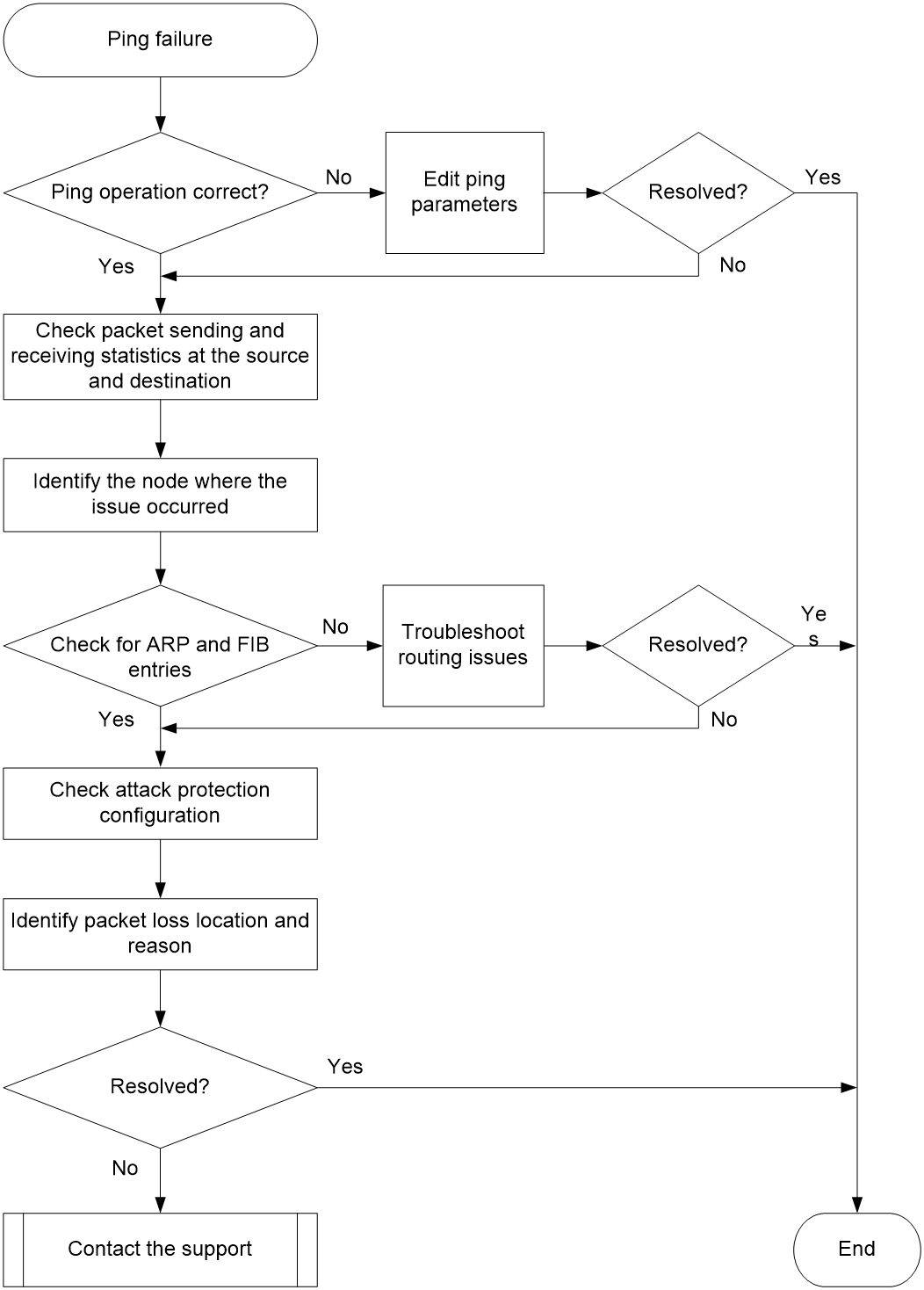
Solution
1. Identify whether the parameters for the ping operation are correct and adjust the parameters as required.
a. Identify whether the transmission delay is too long.
Identify whether the ping -t timeout command has been executed. If so, increase the value of the -t option (1000 as a best practice) or remove it and perform the ping operation again. If the issue is resolved, the issue might be caused by large network delay. If the issue persists, go to the next step.
The -t option specifies the timeout time (in milliseconds) of an ICMP echo reply. The default is 2000. If the source does not receive an ICMP echo reply before the timeout timer expires, it determines that the ICMP echo reply has timed out.
b. Identify whether the ping packet is discarded because it is too large.
Identify whether the ping -f –s packet-size command has been executed. If it has and the MTU for an outgoing interface on the packet forwarding path is smaller than packet-size, the packet will be discarded, because it is too large and cannot be fragmented. To resolve the issue, reduce the packet length or remove the -f keyword.
The -f option sets the "do-not-fragment" bit in the IP header. The ICMP echo requests will not be fragmented.
The -s packet-size option specifies the length (in bytes) of ICMP echo requests (excluding the IP packet header and the ICMP packet header). The default is 56. The default MTU for an Ethernet interface is 1500 bytes. To view the MTU for an interface, execute the display interface command.
<Sysname> display interface gigabitethernet 0/0/1
GigabitEthernet0/0/1
Current state: UP
Line protocol state: UP
Description: GigabitEthernet0/0/1 Interface
Bandwidth: 1000000 kbps
Maximum transmission unit: 1500
...
c. Identify whether a wrong outgoing interface is specified.
Identify whether the ping -i interface-type interface-number command has been executed to specify the outgoing interface for ping packets. If an outgoing interface is specified, make sure the physical link between the interface and the destination is reachable. If no outgoing interface is specified, specify another interface or remove the -i option.
The -i interface-type interface-number option specifies the source interface for ICMP echo requests. If you do not specify this option, the system uses the primary IP address of the matching route's egress interface as the source interface for ICMP echo requests.
d. Identify whether a source address is specified.
Identify whether the ping –a source-ip command has been executed to specify the source address for ping packets. If this command has been executed, make sure the intermediate device and the destination have a route to the source IP address.
The -a source-ip option specifies an IP address of the device as the source IP address for ICMP echo requests. If this option is not specified, the source IP address for ICMP echo requests is the primary IP address of the outgoing interface.
e. Identify whether a correct VPN is specified for the destination.
Based on network planning and deployment, determine whether the destination belongs to a specific VPN. If the destination belongs to a VPN, specify the -vpn-instance keyword in the ping command.
2. Check the packet statistics for the source, destination, and intermediate devices to determine the device where the ping failure occurred.
¡ Identify whether the source has sent an ICMP echo request and received an ICMP echo reply.
After you perform the ping operation at the source, execute the display icmp statistics command at both the source and destination to check the ICMP packet transmission status. You can determine the orientation of the ping failure based on the number of packets in the Input and Output sections in the statistics:
- If the echo value in the Output section at the source is increasing normally, but the echo replies value in the Input section is not, it indicates that the source has sent a request but has not received any response. If the counts in both the Input and Output sections at the destination remain unchanged, it indicates that the destination neither received the request nor responded. Then, you can determine that a forwarding failure of ping packets has occurred from the source to the destination.
- If the echo value in the Output section at the source is increasing normally, but the echo replies value in the Input section is not, it indicates that the source has sent a request but has not received any response. If the counts in both the Input and Output sections at the destination are increasing normally, it indicates that the destination has received the request and has responded. Then, you can determine that a forwarding failure of ping packets has occurred from the destination to the source.
The output from the display icmp statistics command is shown as follows:
<Sysname> display icmp statistics
Input: bad formats 0 bad checksum 0
echo 1 destination unreachable 0
source quench 0 redirects 0
echo replies 0 parameter problem 0
timestamp 0 information requests 0
mask requests 0 mask replies 0
time exceeded 0 invalid type 0
router advert 0 router solicit 0
broadcast/multicast echo requests ignored 0
broadcast/multicast timestamp requests ignored 0
Output: echo 0 destination unreachable 0
source quench 0 redirects 0
echo replies 1 parameter
problem 0
timestamp 0 information replies 0
mask requests 0 mask replies 0
time exceeded 0 bad address 0
packet error 0 router advert 0
...
|
|
IMPORTANT: · If the destination is a modular device or an IRF member device, and the ICMP packet has reached the destination without being fragmented, execute the display icmp statistics command with the slot parameter at the destination to view the ICMP packet statistics. The slot parameter indicates the slot where the interface that received the ICMP packet is located. · If the destination is a modular device or an IRF member device and the ICMP packet is fragmented before it reaches the destination, execute the display icmp statistics command at the destination to view ICMP packet statistics. |
3. Identify the node where the failure occurred.
After you determine the orientation of the ping failure, execute the tracert command to identify the location where the packet was discarded in that direction.
¡ If there are issues from the source to the destination, start troubleshooting from the source.
¡ If there are issues from the destination to the source, start troubleshooting from the destination.
As shown in the example below, execute the tracert command to view the path a packet traverses from the source to the destination and information about Layer 3 devices in the private network it traverses. The destination has an IP address of 1.1.3.2 and belongs to vpn1.
<Sysname> tracert –vpn-instance vpn1 –resolve-as vpn 1.1.3.2
traceroute to 1.1.3.2 (1.1.3.2), 30 hops at most, 40 bytes each packet, press CTRL+C to break
1 1.1.1.2 (1.1.1.2) 673 ms 425 ms 30 ms
2 1.1.2.2 (1.1.2.2) 580 ms 470 ms 80 ms
3 * * *
The output shows that the ping packet experienced a forwarding failure at the next hop device at 1.1.2.2 (the node displayed as 3 * * *).
4. Check for FIB and ARP entries to both the destination and source.
Perform the following operations on the node where the failure occurred:
¡ Execute the display fib command to check for routes to the destination and source. If no routes exist, check the configuration of routing protocols such as OSPF, IS-IS, and BGP for errors.
¡ If the routes exist and the packets traverse over an Ethernet link, execute the display arp command to check for required ARP entries. If the ARP entries are missing, first troubleshoot ARP issues.
5. Identify whether ICMP attack prevention is configured on the node that has ping failures.
If the device is configured with ICMP attack prevention policies and an ICMP attack is detected, it will discard the ICMP packets, resulting in ping failure.
¡ Execute the display attack-defense icmp-flood statistics ip command to display flood attack detection and prevention statistics and identify whether the device is under ICMP attacks.
¡ Execute the display current-configuration | include icmp-flood and display current-configuration | include “signature detect” commands to identify whether attack prevention policies are configured.
If the device is under an ICMP attack, first locate and mitigate the ICMP attack.
6. Identify the location where the packets were discarded and reason based on packet transmission statistics.
On the device along the ping packet transmission path:
a. Configure a QoS policy to use ACLs to filter ping packets, and then apply the QoS policy in both the inbound and outbound directions of the interface where the ping packets traverse.
b. Execute the display qos policy interface command to check the number of IP packets successfully matched by the QoS policy on the interface. If the number increases, it indicates that the device has received a ping packet. If there is no increase, the device has not received any ping packet. In this case, execute the debugging ip packet command to enable IP packet debugging and further troubleshoot and resolve the issue.
7. If the issue persists, collect the following information and contact Technical Support:
¡ Results of each step.
¡ The configuration file, log messages, and alarm messages.
Related alarm and log messages
Alarm messages
None.
Log messages
None.
Tracert failure
Symptom
The output from the tracert command contains line ***, indicating that some nodes are unreachable to each other and the tracert operation has failed.
Common causes
The following are the common causes for this type of issue:
· No corresponding route or ARP entries exist.
· Sending ICMP timeout packets is not enabled on the intermediate device.
· Sending ICMP destination unreachable packets is not enabled at the destination.
Analysis
The troubleshooting flow for issues of this type is as follows:
1. Identify whether the intermediate device is enabled to send ICMP timeout packets.
2. Identify whether the destination is enabled to send ICMP destination unreachable packets.
3. Check for ARP and FIB entries that reach the destination.
Figure 2 shows the fault diagnosis flowchart.
Figure 2 Flowchart for troubleshooting tracert failure
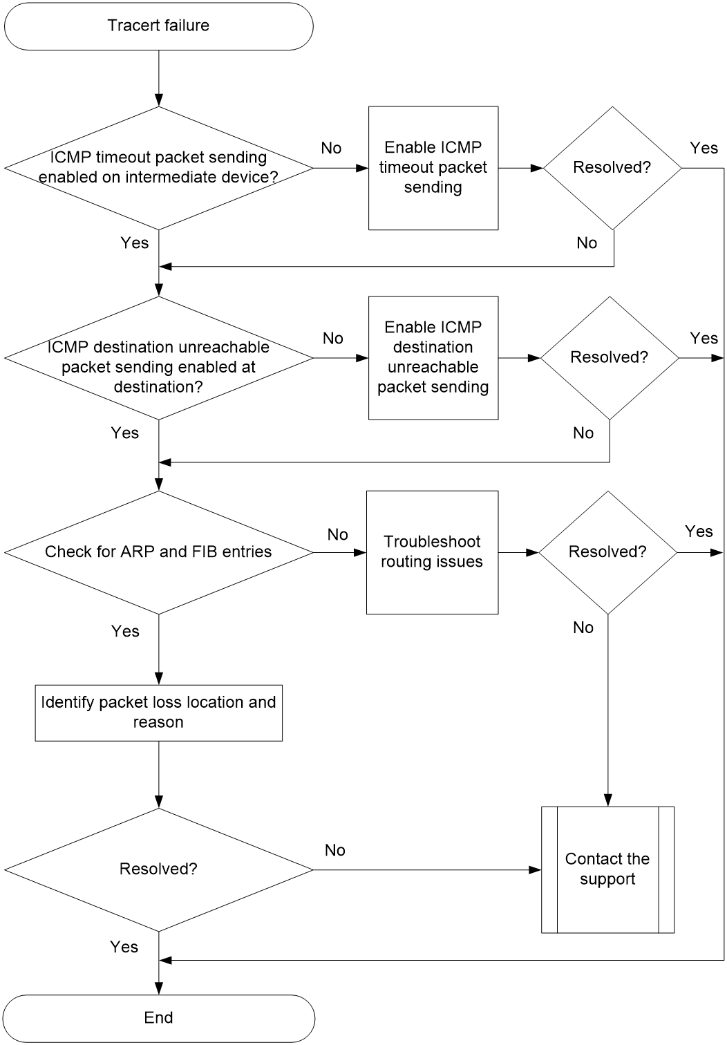
Solution
To resolve the issue:
1. Identify whether the intermediate device is enabled to send ICMP timeout packets.
# View the path that the packets traverse from the source to the destination (assuming there are only two hops from source to destination, with the destination IP address as 1.1.2.2).
<Sysname> tracert 1.1.2.2
traceroute to 1.1.2.2 (1.1.2.2), 30 hops at most, 40 bytes each packet, press CTRL+C to break
1 * * *
2 1.1.2.2 (1.1.2.2) [AS 100] 580 ms 470 ms 80 ms
When the previous output is displayed, log in to the intermediate device and execute the ip ttl-expires enable command to enable sending ICMP timeout packets. If the issue persists, go to the next step.
2. Identify whether the destination is enabled to send ICMP destination unreachable packets.
# View the path that the packets traverse from the source to the destination (assuming there are only two hops from source to destination, with the destination IP address as 1.1.2.2).
<Sysname> tracert 1.1.2.2
traceroute to 1.1.2.2 (1.1.2.2), 30 hops at most, 40 bytes each packet, press CTRL+C to break
1 1.1.1.2 (1.1.1.2) [AS 99] 560 ms 430 ms 50 ms
2 * * *
When the previous output is displayed, log in to the intermediate device and execute the ip unreachables enable command to enable sending ICMP destination unreachable packets. If the issue persists, continue with the following steps.
3. Check for the corresponding FIB and ARP entries on the node where the failure occurred.
Execute the display fib command on the device that has not responded to ICMP error packets (shown as * * * in the output from the tracert command) to check for the route to the destination.
¡ If no routes exist, check the configuration of routing protocols such as OSPF, IS-IS, and BGP for errors.
¡ If the routes exist and the packets traverse over an Ethernet link, execute the display arp command to check for required ARP entries. If the ARP entries are missing, first troubleshoot ARP issues.
4. Identify whether the source has received the ICMP error packets.
Execute the display icmp statistics command multiple times at the source to identify whether it has received ICMP error packets. The output from the command is as follows:
<Sysname> display icmp statistics
Input: bad formats 0 bad checksum 0
echo 0 destination unreachable 9
source quench 0 redirects 0
echo replies 7 parameter problem 0
timestamp 0 information requests 0
mask requests 0 mask replies 0
time exceeded 3 invalid type 0
router advert 0 router solicit 0
broadcast/multicast echo requests ignored 0
broadcast/multicast timestamp requests ignored 0
...
Observe the changes in the statistics about the previous ICMP packets and identify whether the difference in the time exceeded and destination unreachable values in the Input section matches the number of tracert packets sent. If they do not match, it indicates that the sender did not receive the ICMP error packets.
5. Identify the location where the packets were discarded and reason based on packet transmission statistics.
On the device along the tracert packet transmission path:
a. Configure a QoS policy to use ACLs to filter ping packets, and then apply the QoS policy in both the inbound and outbound directions of the interface where the tracert packets traverse.
b. Execute the display qos policy interface command to check the number of IP packets successfully matched by the QoS policy on the interface. If the number increases, it indicates that the device has received a tracert packet. If there is no increase, the device has not received any tracert packet. In this case, execute the debugging ip packet command to enable IP packet debugging and further troubleshoot and resolve the issue.
6. If the issue persists, collect the following information and contact Technical Support:
¡ Results of each step.
¡ The configuration file, log messages, and alarm messages.
Related alarm and log messages
Alarm messages
None.
Log messages
None.
IPv6 ping failure
Symptom
No response is received from the destination within a period of time if a IPv6 ping operation is performed at the source.
Common causes
The following are the common causes for this type of issue:
· The source did not send a request.
· The destination did not send a response.
· Packet loss or long transmission time issues occurred on the intermediate device.
The following are the common causes for this type of issue:
· The transmission delay is long. Even though the source received the response from the destination, the wait timeout timer has expired, causing the IPv6 ping operation to fail.
· The specified parameter values for the ping operation do not match the network capabilities. For example, if an IPv6 ping message is too large, the MTU value for the outgoing interface of the IPv6 ping packet at the intermediate device is smaller, the IPv6 ping packet will be discarded.
· Missing entries in the IPv6 FIB or ND table.
· Attack protection configuration exists.
· Hardware failure.
Analysis
The troubleshooting flow for issues of this type is as follows:
1. Identify whether the parameters for the IPv6 ping operation are correct and adjust the parameters as required.
2. Display IPv6 ping statistics to identify the node where the issue occurred.
3. Check for ND and IPv6 FIB entries that reach the destination.
4. Identify whether the IPv6 ping packets are dropped due to attack protection configuration.
Figure 3 shows the fault diagnosis flowchart.
Figure 3 Flowchart for troubleshooting IPv6 ping operation failure
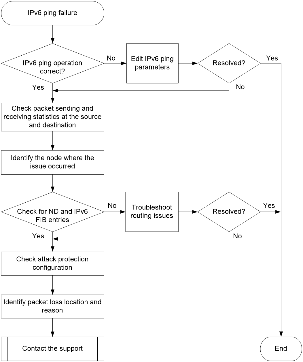
Solution
To resolve the issue:
1. Identify whether the parameters for the IPv6 ping operation are correct and adjust the parameters as required.
a. Identify whether the transmission delay is too long.
Identify whether the ping ipv6 -t timeout command has been executed. If so, increase the value of the -t keyword (1000 as a best practice) or remove the -t option and perform the IPv6 ping operation again. If the issue is resolved, the issue might be caused by large network delay. If the issue persists, go to the next step.
The -t option specifies the timeout time (in milliseconds) of an ICMPv6 echo reply. The default is 2000. If the source does not receive an ICMPv6 echo reply before the timeout timer expires, it determines that the ICMP echo reply timed out.
b. Identify whether the IPv6 ping packet is discarded because it is too large.
Identify whether the ping ipv6 –s packet-size command has been executed. If it has and the MTU for an outgoing interface on the packet forwarding path is smaller than packet-size, the packet will be discarded, because it is too large and cannot be fragmented. To resolve the issue, reduce the packet length.
The -s packet-size option specifies the length (in bytes) of ICMPv6 echo requests (excluding the IPv6 packet header and the ICMPv6 packet header). The default is 56.
The default MTU for an Ethernet interface is 1500 bytes. To view the MTU for an interface, execute the display interface command.
<Sysname> display interface gigabitethernet 0/0/1
GigabitEthernet0/0/1
Current state: UP
Line protocol state: UP
Description: GigabitEthernet0/0/1 Interface
Bandwidth: 1000000 kbps
Maximum transmission unit: 1500
…
c. Identify whether a wrong outgoing interface is specified.
Identify whether the ping ipv6 -i interface-type interface-number command has been executed to specify the outgoing interface for IPv6 ping packets. If an outgoing interface is specified, make sure the physical link between the interface and the destination is reachable. If no outgoing interface is specified, specify another interface or remove the -i option.
The -i interface-type interface-number option specifies the source interface for ICMPv6 echo requests. If you do not specify this option, the system uses the primary IP address of the matching route's egress interface as the source interface for ICMPv6 echo requests.
d. Identify whether a source address is specified.
Identify whether the ping ipv6 –a source-ip command has been executed to specify the source address for IPv6 ping packets. If this command has been executed, make sure the intermediate device and the destination have a route to the source IP address.
The -a source-ip option specifies an IPv6 address of the device as the source IPv6 address for ICMPv6 echo requests. If this option is not specified, the source IPv6 address for ICMPv6 echo requests is the primary IPv6 address of the outgoing interface.
e. Identify whether a correct VPN is specified for the destination.
Based on network planning and deployment, determine whether the destination belongs to a specific VPN. If the destination belongs to a VPN, specify the -vpn-instance keyword in the ping ipv6 command.
2. Check the packet statistics for the source, destination, and intermediate devices to determine the device where the IPv6 ping failure occurred.
¡ Identify whether the source has sent an ICMPv6 echo request and received an ICMPv6 echo reply.
After you perform the IPv6 ping operation at the source, execute the display ipv6 icmp statistics command at both the source and destination to check the ICMPv6 packet transmission status. You can determine the orientation of the ping failure based on the number of packets in the Input and Output fields in the statistics:
- If the echo value in the Output section at the source is increasing normally, but the echo reply value in the Input section is not, it indicates that the source has sent a request but has not received any response. If the counts in both the Input and Output sections at the destination remain unchanged, it indicates that the destination neither received the request nor responded. Then, you can determine that a forwarding failure of IPv6 ping packets has occurred from the source to the destination.
- If the echo value in the Output section at the source is increasing normally, but the echo reply value in the Input section is not, it indicates that the source has sent a request but has not received any response. If the counts in both the Input and Output sections at the destination are increasing normally, it indicates that the destination has received the request and has responded. Then, you can determine that a forwarding failure of IPv6 ping packets has occurred from the destination to the source.
The output from the display ipv6 icmp statistics command is shown as follows:
<Sysname> display ipv6 icmp statistics
Input: bad code 0 too short 0
checksum error 0 bad length 0
path MTU changed 0 destination unreachable 0
too big 0 parameter problem 0
echo request 1 echo reply 0
neighbor solicit 0 neighbor advertisement 0
router solicit 0 router advertisement 0
redirect 0 router renumbering 0
output: parameter problem 0 echo request 0
echo reply 1 unreachable no route 0
unreachable admin 0 unreachable beyond scope 0
unreachable address 0 unreachable no port 0
too big 0 time exceed transit 0
time exceed reassembly 0 redirect 0
ratelimited 0 other errors 0
|
|
IMPORTANT: · If the destination is a modular device or an IRF member device, and the ICMPv6 packet has reached the destination without being fragmented, execute the display ipv6 icmp statistics command with the slot parameter at the destination to view the ICMPv6 packet statistics. The slot parameter indicates the slot where the interface that received the ICMPv6 packet is located. · If the destination is a modular device or an IRF member device and the ICMPv6 packet is fragmented before it reaches the destination, execute the display ipv6 icmp statistics command at the destination to view ICMPv6 packet statistics. |
3. Identify the node where the failure occurred.
After you determine the orientation of the IPv6 ping failure, execute the tracert ipv6 command to identify the location where the packet was discarded in that direction.
¡ If there are issues from the source to the destination, start troubleshooting from the source.
¡ If there are issues from the destination to the source, start troubleshooting from the destination.
As shown in the example below, perform the IPv6 tracert operation to view the path a packet traverses from the source to the destination and information about Layer 3 devices it traverses. The destination has an IPv6 address of 2::2.
<Sysname> tracert ipv6 2::2
traceroute to 2::2 (2::2), 30 hops at most, 104 byte packets, press CTRL_C to break
1 1::2 1.000 ms 0.000 ms 1.000 ms
2 * * *
The output shows that the IPv6 ping packet experienced a forwarding failure at the next hop device at 1::2 (the node displayed as 2 * * *).
To perform the IPv6 tracert operation:
¡ Execute the ipv6 unreachables enable command in system view of the intermediate device to enable sending ICMPv6 time exceeded messages.
¡ Execute the ipv6 unreachables enable command to enable sending ICMP destination unreachable packets in system view of the destination device.
4. Check for IPv6 FIB and ND entries to the destination and source.
Perform the following operations on the node where the failure occurred:
¡ Execute the display ipv6 fib command to check for routes to the destination and source. If no routes exist, check the configuration of routing protocols such as IGP and BGP for errors.
¡ If the routes exist and the packets traverse over an Ethernet link, execute the display ipv6 neighbors command to check for required ND entries. If the ND entries are missing, first troubleshoot ND issues.
5. Identify whether ICMPv6 attack prevention is configured on the node that has ping failures.
If the device is configured with ICMPv6 attack prevention policies and an ICMPv6 attack is detected, it will discard the ICMPv6 packets, resulting in IPv6 ping failure.
¡ Execute the display attack-defense icmpv6-flood statistics ipv6 command to display flood attack detection and prevention statistics and determine if the device is under ICMPv6 attacks.
¡ Execute the display current-configuration | include icmpv6-flood and display current-configuration | include “signature detect” commands to identify whether attack prevention policies are configured.
If the device is under an ICMPv6 attack, first locate and mitigate the ICMPv6 attack.
6. Identify the packet loss location and reason based on packet transmission statistics.
On the devices along the IPv6 ping packet transmission path:
a. Configure a QoS policy to use IPv6 ACLs to filter IPv6 ping packets, and then apply the QoS policy in both the inbound and outbound directions of the interface where the IPv6 ping packets traverse.
b. Execute the display qos policy interface command to check the number of IPv6 packets successfully matched by the QoS policy on the interface. If the number increases, it indicates that the device has received an IPv6 ping packet. If there is no increase, the device has not received any IPv6 ping packet. In this case, execute the debugging ipv6 packet command to enable IPv6 packet debugging and further troubleshoot and resolve the issue.
7. If the issue persists, collect the following information and contact Technical Support:
¡ Results of each step.
¡ The configuration file, log messages, and alarm messages.
Related alarm and log messages
Alarm messages
None.
Log messages
None.