- Table of Contents
-
- 10-Segment Routing Configuration Guide
- 00-Preface
- 01-SR-MPLS configuration
- 02-SR-MPLS TE policy configuration
- 03-SRv6 configuration
- 04-SRv6 TE policy configuration
- 05-SRv6 VPN overview
- 06-IP L3VPN over SRv6 configuration
- 07-EVPN L3VPN over SRv6 configuration
- 08-EVPN VPWS over SRv6 configuration
- 09-EVPN VPLS over SRv6 configuration
- 10-Public network IP over SRv6 configuration
- 11-SRv6 OAM configuration
- 12-SRv6 network slicing configuration
- 13-SRv6 service chain configuration
- Related Documents
-
| Title | Size | Download |
|---|---|---|
| 12-SRv6 network slicing configuration | 503.27 KB |
Configuring SRv6 network slicing
Operating mechanism in SRv6 BE scenarios
Operating mechanism in the SRv6 TE policy scenario
SRv6 network slicing tasks at a glance
SRv6 network slicing tasks at a glance in the SRv6 TE policy scenario
SRv6 network slicing tasks at a glance in SRv6 BE scenarios
Configuring the protocol number for IPv6 hop-by-hop extension headers
Enabling the feature of carrying an NSI ID in the IPv6 source address of network slice packets
Configuring IPv6 source address prefixes for NSI ID encapsulation
Configuring IS-IS to advertise IPv6 source address prefixes used for NSI ID encapsulation
Configuring network slice channels on an interface
Associating a slicing interface with a base interface
Configuring the NSI ID for an SRv6 TE policy candidate path
Mapping a BGP route color to an NSI
Using a static BFD session to detect the connectivity of network slice channels
Configuring network slice packet statistics
Display and maintenance commands for SRv6 network slicing
SRv6 network slicing configuration examples
Example: Configuring SRv6 network slicing in the SRv6 TE policy scenario (HBH slicing)
Example: Configuring SRv6 network slicing in the SRv6 TE policy scenario (source address slicing)
Example: Configuring SRv6 network slicing in the IPv4 L3VPN over SRv6 BE scenario (HBH slicing)
Configuring SRv6 network slicing
About SRv6 network slicing
SRv6 network slicing divides an SRv6 network into multiple independent virtual networks. You can deploy different policies for different virtual networks based on their service types. Virtual networks are overlay networks. Multiple virtual networks can use the same underlay network.
Basic concepts
SRv6 network slicing has the following concepts:
· Network slice instance (NSI)—An independent virtual network in an SRv6 network with network slicing deployed. A virtual network is identified by its unique NSI ID (also called slice ID). You can define the common attributes for a slice through the NSI. For example, you can configure the description for the slice.
· Network slice packet—An IPv6 packet transmitted in the NSI. The header of a network slice packet carries the NSI ID used for identifying the NSI to which the packet belongs. The NSI ID (or slice ID) can be encapsulated in different positions in the IPv6 packet. According to the position of the NSI ID in a network slice packet, the device supports the following encapsulation methods:
¡ HBH slicing method—Uses the option field of the IPv6 hop-by-hop extension header to carry NSI ID information. If this method is used, the device needs to parse the IPv6 hop-by-hop extension header to obtain the NSI ID information and increase the length of IPv6 packets. The efficiency of parsing and forwarding packets is slightly low, but this method has good scalability. By default, the SRv6 source node uses the HBH slicing method to encapsulate an NSI ID in network slice packets.
¡ Source address slicing method—Uses the least significant 32 bits of the source address in IPv6 packets to carry NSI ID information. To use this method, you must plan the 128-bit source address properly. The advantage is that the device only needs to parse the IPv6 basic header to obtain the NSI ID information and does not need to increase the length of IPv6 packets. The overhead of the packet header is small, and the device can parse and forward packets more efficiently.
¡ Network slice channel—A logical channel on an interface, used for forwarding network slice packets. A network slice channel is associated with an NSI by the NSI ID. You can create multiple network slice channels on an interface and assign an independent scheduling queue to each network slice channel. In this way, the scheduling queues for network slice channels do not affect each other.
In an SRv6 network slicing scenario, the device uses the following types of interfaces to process network slice packets:
· Base interface—When forwarding network slice packets, the device looks up the FIB table for the destination address (SRv6 SID) of the packets to find a base interface that acts as the output interface. Make sure the base interface has an IP address for participating in route calculation. The IP address does not necessarily participate in forwarding the packets.
· Slicing interface—A slicing interface uses the network slice channels created on it to forward network slice packets.
Network slice packet format
HBH slicing method for NSI ID encapsulation
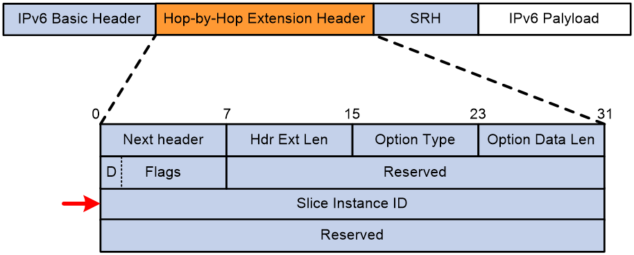
When an SRv6 source node uses the HBH slicing method to encapsulate NSI ID information in a packet, it adds an IPv6 hop-by-hop extension header to the packet. The IPv6 hop-by-hop extension header contains an NSI ID. As shown in Figure 1, an IPv6 hop-by-hop extension header contains the following key fields:
· Option Type—This field takes value 0x1D, indicating that the option is an NSI ID option.
· Flags—This field is 8 bits long. The first bit of it is D flag (drop flag).
¡ When the D flag is set to 0, the device can still forward a network slice packet out of an output interface even if that output interface does not have a network slice channel associated with the NSI to which the packet belongs. When forwarding the packet out of the interface, the device ignores the NSI ID information in the network slice packet.
¡ When the D flag is set to 1, the device drops a network slice packet if no output interface has a network slice channel associated with the NSI to which the packet belongs. When forwarding the packet, the device does not ignore the NSI ID information in the network slice packet.
· Slice Instance ID—ID of the NSI to which the packet belongs. This field is 32 bits long. This field can also be abbreviated as slice ID.
Figure 1 IPv6 hop-by-hop extension header that contains an NSI ID
Source address slicing method for NSI ID encapsulation
When the SRv6 source node uses the source address slicing method to encapsulate NSI ID information, you must properly plan and configure the IPv6 source address. Figure 2 shows the packet structure. Figure 3 shows components contained in the IPv6 source address field.
Figure 2 Structure for packets with an NSI ID encapsulated by using the source address slicing method
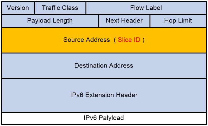
Figure 3 Components of the IPv6 source address that carries an NSI ID
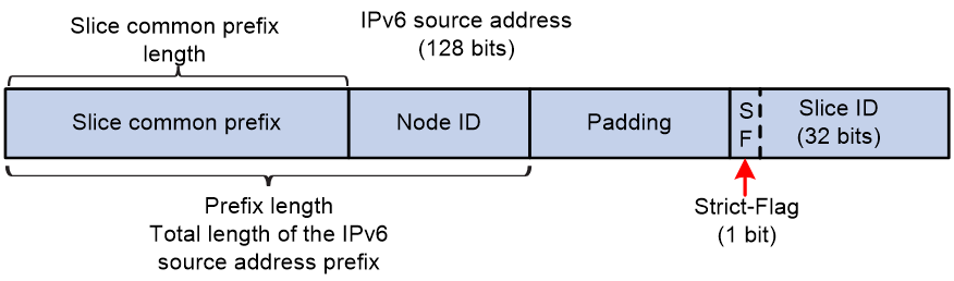
The IPv6 source address that carries an NSI ID includes the following components:
· Slice common prefix—Used to identify that the IPv6 source address carries NSI ID information. The component is dedicated to slicing, and it is located in the highest significant bits of the IPv6 source address. You can specify the length of the slice common prefix. Typically, all devices in the same network use the same slice common prefix.
· Node ID—Used to identify different devices in the same network. The slice common prefix and node ID together form the prefix of the IPv6 source address that carries an NSI ID. The device can use IS-IS to advertise this prefix to other devices and use this prefix for inter-device routing. In addition, the device generates a direct route entry in the local FIB table based on this prefix.
· NSI ID (slice ID)—Least significant 32 bits of the IPv6 source address. The first bit is the Strict-Flag flag bit.
¡ If this flag bit is set to 1 in a network slice packet, the device must forward the packet through a network slice channel bound to the NSI ID. If no network slice channels are bound to the NSI ID, the device discards the packet.
¡ If this flag bit is set to 0 in a network slice packet, the device searches for a network slice channel bound to the NSI ID to forward the packet. If no network slice channels are bound to the NSI ID, the device does not discard the packet. Instead, it forwards the packet according to the SRv6 packet forwarding process.
Based on IPv6 address planning, you can configure the highest four bits in the 32-bit NSI ID as the reserved portion. The bits in the reserved portion can be used for other purposes. For example, they can be used as extended flag bits.
· Padding—If the total length of the slice common prefix, node ID, and NSI ID is less than 128 bits, fill with 0s after the IPv6 source address prefix to make up for it.
Operating mechanism in SRv6 BE scenarios
About the operating mechanism
SRv6 network slicing can be applied to the IP L3VPN over SRv6 BE, EVPN L3VPN over SRv6 BE, public network IP over SRv6 BE, EVPN VPLS over SRv6 BE, and EVPN VPWS over SRv6 BE scenarios.
BGP route learning on the control plane is essential to implement SRv6 network slicing in SRv6 BE scenarios. To forward traffic in a network slice identified by an NSI ID, the local PE must learn BGP routes that include the color extended community attribute from remote PEs and associate the color extended community attribute of the BGP routes with the NSI ID. When the destination address of a data packet matches such a BGP route, the device associates the packet with the NSI ID and forwards it through the network slice identified by the NSI ID.
The following information describes packet forwarding in an IP L3VPN over SRv6 BE network.
Route learning on the control plane
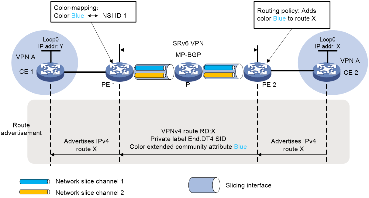
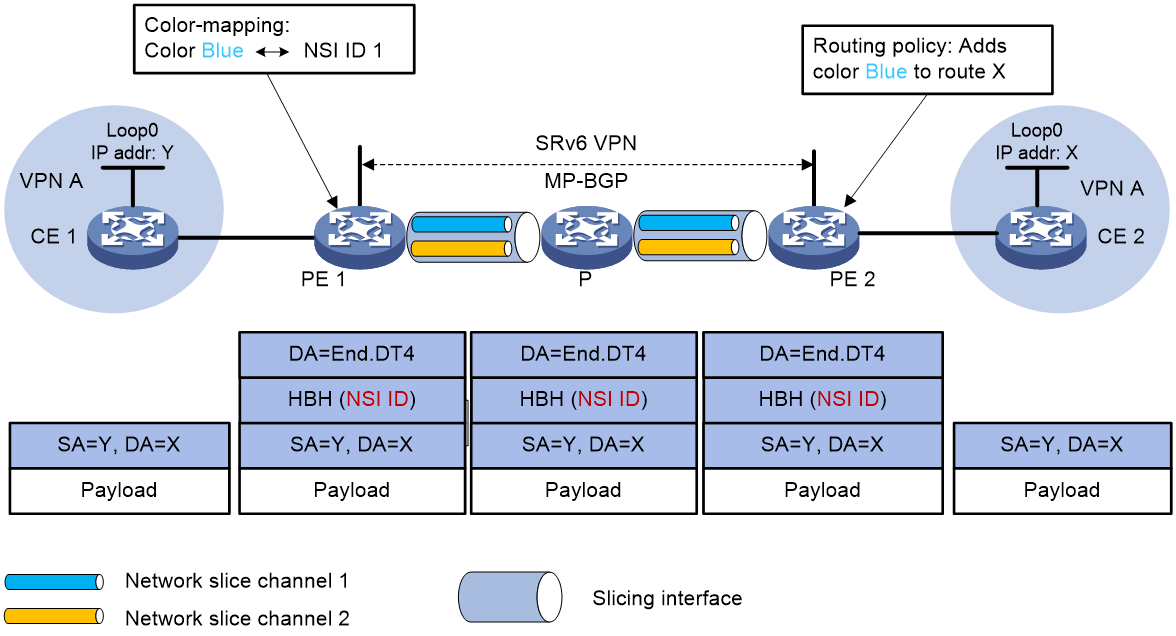
As shown in Figure 4, NSI 1 and NSI 2 exist in the SRv6 network. On the slicing interfaces of PE 1, P, and PE 2, network slice channel 1 and network slice channel 2 are associated with NSI 1 and NSI 2, respectively. Traffic between CE 1 and CE 2 in VPN A is forwarded over the SRv6 BE tunnel. The private route of CE 2 is advertised to CE 1 as follows:
1. CE 2 uses IGP or BGP to advertise local private route X of Loopback 0 to PE 2.
2. After PE 2 learns the private route from CE 2, it adds the route to the routing table of VPN A. In addition, PE 2 performs the following operations for the route:
a. Adds RD and route target attributes and allocates an End.DT4 SID to the route. The route becomes VPNv4 route RD:X.
b. Uses a routing policy to add the color extended community attribute to the VPNv4 route. The attribute value is Blue.
c. Uses MP-BGP to advertise the VPNv4 route that includes the color extended community attribute to PE 1.
3. When PE 1 receives the VPNv4 route, it adds the route to the routing table of VPN A and records the color extended community attribute of the route as Blue. On PE 1, Blue is mapped to NSI 1.
4. PE 1 converts the VPNv4 route to IPv4 route X and advertises the IPv4 route to CE 1.
5. When CE 1 receives the route, it learns the route to the routing table.
Figure 4 Routing learning on the control plane in an IP L3VPN over SRv6 BE network
Packet forwarding on the data plane
As shown in Figure 5, when the HBH slicing method is used for NSI ID encapsulation, a private network packet is forwarded from CE 1 to CE 2 as follows:
1. CE 1 sends an IPv4 packet with destination address X to PE 1.
2. When PE 1 receives the packet from an interface associated with VPN A, it performs the following operations:
a. PE 1 looks up the routing table of VPN A for a route matching the destination address.
b. PE 1 obtains the End.DT4 SID corresponding to the destination address. Upon finding that the color attribute (Blue) of the matching route is mapped to NSI 1, PE 1 adds an IPv6 header and an HBH extension header to the packet. The HBH extension header includes NSI ID 1 to indicate that the packet will be forwarded through the network slice with NSI ID 1.
3. PE 1 performs the following operations:
a. Looks up the IPv6 FIB based on the End.DT4 and finds that the output interface is an interface connected to P.
b. Searches for the network slice channel associated with the NSI ID on the output interface and uses the optimal IGP route to forward the packet to P through the channel.
4. P looks up the IPv6 FIB based on the End.DT4, and repeats the steps performed by PE 1 to use the optimal IGP route to forward the packet to PE 2.
5. After PE 2 receives the packet, it performs the following operations:
a. Removes the IPv6 header from the packet.
b. Matches the packet to VPN A based on the End.DT4 SID and looks up the routing table of VPN A.
c. Forwards the packet to CE 2.
Figure 5 Packet forwarding in an IP L3VPN over SRv6 BE network
Operating mechanism in the SRv6 TE policy scenario
About the operating mechanism
To use SRv6 network slicing in the SRv6 TE policy scenario, you must associate the candidate paths of SRv6 TE policies with NSI IDs. Once the source node of an SRv6 TE policy steers traffic to a candidate path of that policy, the device forwards the traffic in the NSI whose NSI ID is associated with the candidate path.
In the SRv6 TE policy scenario, you do not need to establish a mapping between the color extended community attribute and the NSI ID of each BGP route. You only need to steer traffic to SRv6 TE policies. In this scenario, you do not need to change the routing learning procedure on the control plane.
The following information describes how SRv6 network slice packets are forwarded in an IP L3VPN over SRv6 TE policy network.
Packet forwarding on the data plane
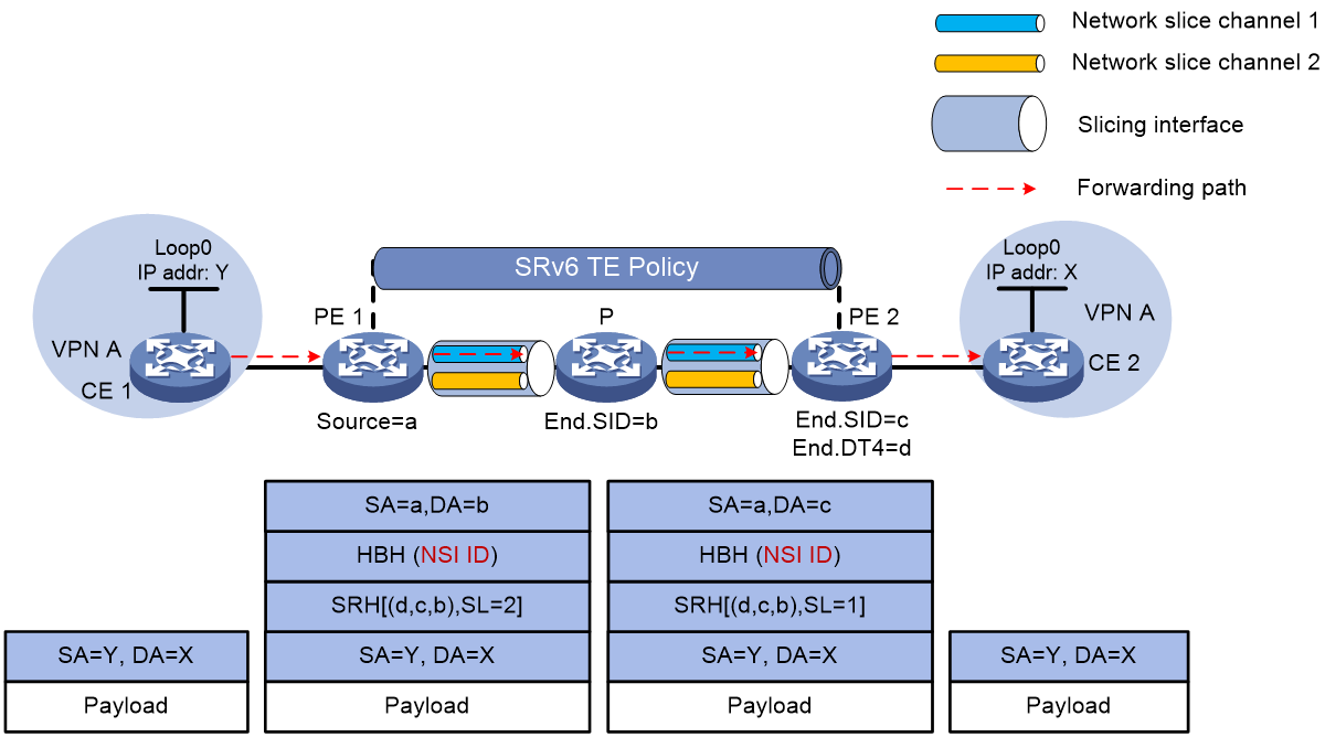
As shown in Figure 6, NSI 1 and NSI 2 exist in the SRv6 network. On the slicing interfaces of PE 1, P, and PE 2, network slice channel 1 and network slice channel 2 are associated with NSI 1 and NSI 2, respectively. Traffic between CE 1 and CE 2 in VPN A is forwarded through a path in an SRv6 TE policy associated with NSI 1. When the HBH slicing method is used for NSI ID encapsulation, a packet from CE 1 to CE 2 is forwarded as follows:
1. CE 1 sends an IPv4 unicast packet to PE 1.
2. After receiving the packet from CE 1, PE 1 looks up the routing table of VPN A and finds the route that uses an SRv6 TE policy as the output interface. Then, PE 1 encapsulates the following information into the packet:
¡ The SRH header that carries the SID list of the SRv6 TE policy.
¡ The HBH extension header that carries the NSI ID associated with the selected candidate path of the SRv6 TE policy. The NSI ID is 1.
¡ IPv6 basic header.
3. PE 1 forwards the packet to P through the network slice channel that matches the NSI ID.
4. P forwards the packet based on the SRH header through the network slice channel that matches the NSI ID.
5. After receiving the packet, PE 2 performs the following operations:
a. Looks up the local SID list based on the destination IPv6 address of the packet, and finds the End SID.
b. Reduces the SL of the packet by 1, and updates the destination IPv6 address to the End.DT4 SID.
c. Looks up the local SID list, and performs the forwarding action corresponding to the End.DT4 SID. That is, PE 2 decapsulates the IPv6 header, finds VPN A that matches the End.DT4 SID, looks up the routing table of VPN A, and then forwards the packet to CE 2.
Figure 6 Packet forwarding in an IP L3VPN over SRv6 TE policy network
SRv6 network slicing tasks at a glance
SRv6 network slicing tasks at a glance in the SRv6 TE policy scenario
HBH slicing method
To use the HBH slicing method to configure SRv6 network slicing in the SRv6 TE policy scenario, perform the following tasks:
1. Creating an SRv6 TE policy and configuring its basic attributes
Perform this task on the source node of the SRv6 network. For more information, see "Configuring SRv6 TE policies."
2. Configuring traffic steering to the SRv6 TE policy
For more information, see "Configuring SRv6 TE policies."
3. Creating SRv6 NSIs and configuring their basic attributes
b. Configuring the protocol number for IPv6 hop-by-hop extension headers
4. Configuring network slice channels on an interface
5. (Optional.) Associating a slicing interface with a base interface
6. Configuring the NSI ID for an SRv6 TE policy candidate path
7. (Optional.) Configuring network slice packet statistics
Source address slicing method
To use the source address slicing method to configure SRv6 network slicing in the SRv6 TE policy scenario, perform the following tasks:
1. Creating an SRv6 TE policy and configuring its basic attributes
Perform this task on the source node of the SRv6 network. For more information, see "Configuring SRv6 TE policies."
2. Configuring traffic steering to the SRv6 TE policy
For more information, see "Configuring SRv6 TE policies."
4. Enabling the feature of carrying an NSI ID in the IPv6 source address of network slice packets
5. Configuring IPv6 source address prefixes for NSI ID
6. Configuring IS-IS to advertise IPv6 source address prefixes used for
7. Configuring network slice channels on an interface
8. (Optional.) Associating a slicing interface with a base interface
9. Configuring the NSI ID for an SRv6 TE policy candidate path
10. (Optional.) Configuring network slice packet statistics
SRv6 network slicing tasks at a glance in SRv6 BE scenarios
HBH slicing method
To use the HBH slicing method to configure SRv6 network slicing in an SRv6 BE scenario, perform the following tasks:
1. Configuring the service application scenario for SRv6 network slicing and setting the route recursion mode to SRv6 BE
For more information, see "Configuring IP L3VPN over SRv6," "Configuring EVPN L3VPN over SRv6," "Configuring public network IP over SRv6," "Configuring EVPN VPLS over SRv6," or "Configuring EVPN VPWS over SRv6."
2. Creating SRv6 NSIs and configuring their basic attributes
b. Configuring the protocol number for IPv6 hop-by-hop extension headers
3. Configuring network slice channels on an interface
4. (Optional.) Associating a slicing interface with a base interface
5. Mapping a BGP route color to an NSI
6. (Optional.) Using a static BFD session to detect the connectivity of network slice channels
7. (Optional.) Configuring network slice packet statistics
Source address slicing method
To use the source address slicing method to configure SRv6 network slicing in an SRv6 TE scenario, perform the following tasks:
1. Configuring the service application scenario for SRv6 network slicing and setting the route recursion mode to SRv6 BE
For more information, see "Configuring IP L3VPN over SRv6," "Configuring EVPN L3VPN over SRv6," "Configuring public network IP over SRv6," "Configuring EVPN VPLS over SRv6," or "Configuring EVPN VPWS over SRv6."
3. Enabling the feature of carrying an NSI ID in the IPv6 source address of network slice packets
4. Configuring IPv6 source address prefixes for NSI ID
5. Configuring IS-IS to advertise IPv6 source address prefixes used for
6. Configuring network slice channels on an interface
7. (Optional.) Associating a slicing interface with a base interface
8. Mapping a BGP route color to an NSI
9. (Optional.) Using a static BFD session to detect the connectivity of network slice channels
10. (Optional.) Configuring network slice packet statistics
Configuring an SRv6 NSI
Restrictions and guidelines
To delete an NSI associated with an interface, first remove the association.
Procedure
1. Enter system view.
system-view
2. Enable network slicing and enter network slice view.
network-slice
By default, network slicing is disabled.
3. Create an NSI and enter its view.
instance slice-instance-id
4. (Optional.) Configure the description for the NSI.
description text
By default, no description is configured for an NSI.
Configuring the protocol number for IPv6 hop-by-hop extension headers
About this task
With SRv6 network slicing enabled, an SRv6 source node uses the HBH slicing method and adds an IPv6 hop-by-hop extension header to a packet. The IPv6 hop-by-hop extension header contains an NSI ID. By default, the protocol number in an IPv6 hop-by-hop extension header is 0, indicating that the Next Header field of the preceding IPv6 header is 0. Upon receiving a packet, a network slicing incapable device cannot parse the IPv6 hop-by-hop extension header with protocol number 0. As a result, the packet processing becomes slow or the packet is dropped. To avoid such issues, you can use this feature to set the protocol number to a value other than 0. After that, the network slicing incapable device ignores the IPv6 hop-by-hop extension header with protocol number 0, and forwards the packet based on its IPv6 basic header. The protocol number of IPv6 hop-by-hop extension headers varies by vendor. You can edit the protocol number for interoperability between devices from different vendors.
Procedure
1. Enter system view.
system-view
2. Enter network slice view.
network-slice
3. Set the protocol number for IPv6 hop-by-hop extension headers.
protocol-number number
The default protocol number of IPv6 hop-by-hop extension headers is 0.
Enabling the feature of carrying an NSI ID in the IPv6 source address of network slice packets
About this task
An NSI ID can be encapsulated in different positions in an IPv6 network slice packet. According to the position of the NSI ID in the network slice packet, the device supports the following encapsulation methods:
· HBH slicing method.
· Source address slicing method.
By default, the SRv6 source node uses the HBH slicing method to encapsulate an NSI ID in network slice packets. You can use this feature to enable the SRv6 source node to use the source address slicing method.
If source address slicing method is used, network slice packets do not support insertion modes. If an insertion mode is configured, the device will use the corresponding Encaps mode to process network slice packets. For more information about insertion modes, see "Configuring SRv6 TE policies."
Procedure
1. Enter system view.
system-view
2. Enter network slice view.
network-slice
3. Enable the feature of carrying an NSI ID in the IPv6 source address of network slice packets.
slice-encapsulation ipv6-source
By default, an NSI ID is encapsulated in the IPv6 hop-by-hop extension header of network slice packets.
Configuring IPv6 source address prefixes for NSI ID encapsulation
About this task
If the SRv6 source node uses source address slicing for NSI ID encapsulation, you must configure IPv6 source address prefixes on the SRv6 source node. The source node will encapsulate an IPv6 source address in network slice packets based on the IPv6 source address prefixes.
You must also execute the index prefix-name command on the transit nodes along the SRv6 forwarding path to configure an IPv6 source address prefix for NSI ID encapsulation. When a transit node forwards a packet, it performs one of the following operations:
· Exact match: Without the match-mask keyword specified, the node compares the highest significant common-length bits of the IPv6 source address in the packet with the slice common prefixes configured in the IPv6 source address prefixes. If they are identical, the packet is a network slice packet with NSI ID information carried in its source address. The node will read the NSI ID information from the IPv6 source address of the packet.
· Fuzzy match: With the match-mask keyword specified, the node compares the highest significant common-length bits of the IPv6 source address in the packet with the configured slice common prefixes by using the bits set to 1 in the ipv6-address-mask value. The node ignores the bits set to 0 in the ipv6-address-mask value. For example, if you specify the value for the common-length argument as 64 and the value for the ipv6-address-mask argument as FFFF:00FF:FFFF:FFFF:: where bits 17 to 24 are set to 0, the node ignores bits 17 to 24 when comparing the highest significant common-length bits of the IPv6 source address in the packet with the configured slice common prefixes. The node takes the IPv6 source address of the packet as carrying an NSI ID only when other bits are completely consistent.
Restrictions and guidelines
· You can repeat the index prefix-name command to configure multiple IPv6 source address prefixes and specify different index values for the IPv6 source address prefixes. Two IPv6 source address prefixes with different index values and names cannot be completely identical or have overlapping relationships.
· If you execute the index prefix-name command multiple times to configure multiple IPv6 source address prefixes but specify the same index value, only the most recent configuration takes effect.
· To ensure that an IPv6 source address prefix can be advertised by IGP and the reverse packets can be routed back to the SRv6 source node, you must specify the prefix-length prefix-length option when using the index prefix-name command to configure the IPv6 source address prefix on the SRv6 source node. You do not need to specify the prefix-length prefix-length option on the SRv6 transit nodes. These transit nodes only use the slice common prefix to identify whether the received IPv6 packets are network slice packets.
· On the same device, you can specify the default keyword for only one IPv6 source address prefix.
· Use caution when you plan IPv6 source addresses carrying an NSI ID. If the IPv6 source address prefixes for NSI ID encapsulation (configured by the index prefix-name command) and the source address for SRv6 VPN encapsulation (configured by the encapsulation source-address command) overlap, the VPN packets will be forwarded through the network slice channel.
· If you specify the match-mask ipv6-address-mask option for the index prefix-name command, the value for the ipv6-address-mask argument depends on the value for the common-length argument. If the value for the common-length argument is n, the (n + 1)th bit to the 128th bit of the mask specified with the ipv6-address-mask argument can only be 0, and at least one bit from the first bit to the nth bit must be 1. For example, if the value for the common-length argument is 64, the 65th bit to the 128th bit of the mask specified with the ipv6-address-mask argument must be 0, and the value range is 0:0:0:1:: to FFFF:FFFF:FFFF:FFFF::.
|
|
CAUTION: An IPv6 source address prefix carrying an NSI ID needs to be advertised by IS-IS for network-wide IS-IS route convergence. If IS-IS route convergence time and BFD time are not synchronized, BFD service anomalies might occur, as shown in the following example: The candidate paths of an SRv6 TE policy detected by BFD/SBFD uses the NSI ID encapsulated with source address slicing. The IPv6 source address carrying NSI ID needs to be advertised to the endpoint of the SRv6 TE policy through IGP. This enables the endpoint to generate route entries for forwarding return BFD/SBFD packets based on the IPv6 source address. An issue might exist when the IGP convergence time and the time when BFD packets arrive at the endpoint are not synchronized. That is, the endpoint might receive the BFD/SBFD packets from the source node when it has not learned the IPv6 source address carrying the NSI ID advertised by the IGP. If such an issue exists, the return BFD/SBFD packets might be discarded due to unreachable addresses. As a result, the BFD/SBFD session might go down, which causes the SRv6 TE policy to go down. |
Procedure
1. Enter system view.
system-view
2. Enter network slice view.
network-slice
3. Enter slice prefix view.
slice-prefix
4. (Optional.) Configure the reserved portion for the NSI ID of the source address slicing method.
slice-id-reserved bit length
By default, no reserved portion is configured for the NSI ID of the source address slicing method.
5. Configure an IPv6 source address prefix for NSI ID encapsulation.
index index-number prefix-name prefix-name ipv6-prefix ipv6-address common-length common-length [ match-mask ipv6-address-mask ] [ prefix-length prefix-length [ default ] ]
By default, an NSI ID is encapsulated in the IPv6 hop-by-hop extension header of network slice packets.
Configuring IS-IS to advertise IPv6 source address prefixes used for NSI ID encapsulation
About this task
When the SRv6 source node uses source address slicing for NSI ID encapsulation and has IPv6 source address prefixes configured by using the index prefix-name command, use this feature to enable IS-IS to advertise these prefixes to other devices. This allows other devices to use the prefix routes for returning the backward packets to the SRv6 source node.
|
|
CAUTION: An IPv6 source address prefix carrying an NSI ID can be advertised by IS-IS for network-wide IS-IS route convergence. If IS-IS route convergence time and BFD time are not synchronized, BFD service anomalies might occur, as shown in the following example: The candidate paths of an SRv6 TE policy detected by BFD/SBFD uses the NSI ID encapsulated with source address slicing. The IPv6 source address carrying NSI ID needs to be advertised to the endpoint of the SRv6 TE policy through IGP. This enables the endpoint to generate route entries for forwarding return BFD/SBFD packets based on the IPv6 source address. An issue might exist when the IGP convergence time and the time when BFD packets arrive at the endpoint are not synchronized. That is, the endpoint might receive the BFD/SBFD packets from the source node when it has not learned the IPv6 source address carrying the NSI ID advertised by the IGP. If such an issue exists, the return BFD/SBFD packets might be discarded due to unreachable addresses. As a result, the BFD/SBFD session might go down, which causes the SRv6 TE policy to go down. |
Procedure
1. Enter system view.
system-view
2. Enter IS-IS view.
isis [ process-id ] [ vpn-instance vpn-instance-name ]
3. Enter IS-IS IPv6 address family view.
address-family ipv6 [ unicast ]
4. Configure IS-IS to advertise IPv6 source address prefixes used for NSI ID encapsulation.
advertise slice-prefix-route
Configuring network slice channels on an interface
About this task
Use this feature to create network slice channels on an interface. The device supports the following types of network slice channels:
· Network slice channels in exclusive mode—When you configure a network slice channel on an interface, specify the flex-channel keyword without the shared keyword. The device will allocate exclusive-mode scheduling queue resources to this network slice channel. Network slice packets from other network slice channels and non-network slice packets cannot preempt the scheduling queue resources of this network slice channel. When the NSI ID carried by a network slice packet matches the NSI ID of this network slice channel, the device uses this channel to forward that packet. For example, a network slice channel with NSI ID 10 is operating in exclusive mode and 100 Mbps of bandwidth resources is allocated to this channel. Network slice packets matching other network slice channels and non-network slice packets cannot occupy the resources of this network slice channel, even if this network slice channel does not have traffic.
· Network slice channels in shared mode—When you configure a network slice channel on an interface, specify the flex-channel keyword with the shared keyword. The device will assign shared-mode scheduling queue resources to this network slice channel. Non-network slice packets can compete for the scheduling queue resources of this network slice channel during network congestion. When the NSI ID carried by a network slice packet matches the NSI ID of this network slice channel, the device uses this channel to forward the network slice packet. For example, a network slice channel with NSI ID 20 is operating in shared mode and 100 Mbps of bandwidth resources is allocated to this network slice channel. When this network slice channel does not have traffic but congestion exists on the interface, the resources of this network slice channel can be used by other traffic. You can use the flex-channel-pir keyword to specify a peak information rate (PIR) for a network slice channel in shared mode. The network slice channel will use the rate specified by using the bandwidth-value argument and the PIR to implement the dual-rate dual-bucket three-color algorithm. For more information about the dual-rate dual-bucket three-color algorithm, see QoS configuration in ACL and QoS Configuration Guide. Network slice channels in shared mode enable more flexible traffic scheduling.
· Network slice channels in data plane mode—If you specify the data-plane keyword when creating a network slice channel on an interface, the device does not allocate independent scheduling queue resources to that channel. As a best practice, associate that channel with a slicing interface and do not use it for bandwidth resource isolation. The device dynamically calculates the bandwidth value of that channel on the interface. The services on that channel and the services on non-network slice channels share the remaining bandwidth resources of the interface. As a result, bandwidth resource isolation cannot be achieved among services on the interface. As a best practice to isolate bandwidth resources among services on network slice channels and non-network slice channels, specify the flex-channel keyword when creating network slice channels.
Restrictions and guidelines
Before you enable network slicing, use the instance command to create NSIs.
You can configure multiple network slice channels on an interface.
When you configure network slice channels on base interfaces and slicing interfaces, follow these restrictions and guidelines:
· You can first execute the basic slice-id command on a subinterface, and then use the slice-id { data-plane | flex-channel } command to create network slice channels on that subinterface. If you first execute the slice-id { data-plane | flex-channel } command on a subinterface before associating it with a base interface, you cannot use the basic slice-id command on that subinterface.
· You cannot delete the network slice channels on an interface specified as a base interface of a slicing interface. To delete the network slice channels, first use the undo basic slice-id command on the slicing interface.
· On a slicing interface, you can create only one network slice channel with the data-plane keyword specified.
Use this feature in conjunction with the mode channel-bandwidth command to enable hierarchical slicing capability on a subinterface. You must first execute the mode channel-bandwidth command on the subinterface to isolate bandwidth resources among services on the subinterface and other subinterfaces. Then, use this feature to create network slice channels on the subinterface to further isolate bandwidth resources among services on the network slice channels. The total network slice channel bandwidths specified in the slice-id { data-plane | flex-channel } command on the subinterface cannot exceed the bandwidth configured with the mode channel-bandwidth command on the subinterface minus 300 kbps.
If you execute the slice-id { data-plane | flex-channel } command multiple times to specify the same channel but different bandwidths for the same interface, the most recent configuration takes effect.
To avoid conflicts, do not both configure network slice channels in shared mode on a subinterface and configure the subinterface as a slicing interface.
Only the following interfaces support this feature:
· Layer 3 Ethernet interfaces.
· Layer 3 Ethernet subinterfaces.
· Layer 3 aggregate interfaces.
· Layer 3 aggregate subinterfaces.
· FlexE logical interfaces.
· FlexE logical subinterfaces.
If you configure the network-slice enable command to enable network slicing for the interface, you cannot add the interface to a link aggregate group.
Procedure
1. Enter system view.
system-view
2. Enter interface view.
interface interface-type interface-number
3. Enable network slicing for the interface and enter network slice view of the interface.
network-slice enable
By default, network slicing is disabled for an interface.
4. Configure a network slice channel on the interface and specify the channel bandwidth.
slice-id slice-instance-id { data-plane | flex-channel flex-channel-value [ shared [ flex-channel-pir peak-information-rate ] ] }
By default, no network slice channels are configured on an interface.
Associating a slicing interface with a base interface
About this task
With an NSI specified, a subinterface acts as a slicing interface and is associated with a base interface identified by the NSI. For example, you can execute the slice-id { data-plane | flex-channel } command on an interface to create a network slice channel in NSI 10. To use the interface as a base interface for a subinterface, you can use the basic slice-id command on the subinterface and specify 10 for the match-slice-id argument. The subinterface then acts as a slicing interface. In addition, you must use the slice-id { data-plane | flex-channel } command on the slicing interface to create a network slice channel. The NSI ID of the network slice channel cannot be the same as the value of the match-slice-id argument.
After you associate a slicing interface with a base interface, the device forwards network slice packets as follows:
1. The device looks up the FIB for the destination address (SRv6 SID) of a network slice packet. The output interface of the matching FIB entry is a base interface.
¡ If yes, the device directly forwards the packet through the network slice channel on the base interface. In this case, the base interface is also a slicing interface. This kind of packet forwarding is called interfaceless mode.
¡ If not, the device searches for a slicing interface associated with the base interface based on the NSI ID of the network slice channel on the base interface.
- If no slicing interface is found, the device by default ignores the NSI ID in the packet and forwards the packet according to the general SRv6 packet forwarding procedure.
- If a slicing interface is found, the device further searches for a network slice channel associated with the NSI ID in the packet on the slicing interface. If such a channel is found, the device forwards the packet through that channel on the slicing interface. If such a channel is not found, the device by default ignores the NSI ID in the packet and forwards the packet in regular SRv6 packet forwarding. This kind of packet forwarding is called interface mode.
Restrictions and guidelines
· This feature is supported only on subinterfaces.
· When you configure slicing interfaces, follow these restrictions and guidelines:
¡ A base interface and its associated slicing interfaces must belong to the same main interface.
¡ A slicing interface cannot be associated with other slicing interfaces, and it can be associated only with a base interface. That is, the match-slice-id value specified in the basic slice-id command on one slicing interface cannot be the same as the NSI ID specified in the slice-id { data-plane | flex-channel } command on any other slicing interfaces.
¡ If you execute the basic slice-id command multiple times for the same interface, the most recent configuration takes effect. That is, a slicing interface can be associated with only one base interface.
¡ As a best practice for successfully forwarding network slice packets, follow these guidelines:
- Do not configure an IP address for a subinterface after that subinterface is configured as a slicing interface.
- Make sure the subinterface does not act as a base interface to participate in route calculation.
· When you configure slicing interface and base interface associations, follow these guidelines:
¡ First use the basic slice-id command to specify a base interface for a subinterface, and then use the slice-id { data-plane | flex-channel } command to create network slice channels on the subinterface. If you use the slice-id { data-plane | flex-channel } command on a subinterface before specifying a base interface for the subinterface, you cannot execute the basic slice-id command.
¡ To remove the base interface associated with a slicing interface configured with the slice-id { data-plane | flex-channel } command, you must first use the undo slice-id { data-plane | flex-channel } command to delete all network slice channels on the slicing interface.
Procedure
1. Enter system view.
system-view
2. Enter interface view.
interface interface-type interface-number
3. Enable network slicing for the interface and enter network slice view of the interface.
network-slice enable
By default, network slicing is disabled on an interface.
4. Create a network slice channel on the interface and specify a bandwidth for the channel.
slice-id slice-instance-id { data-plane | flex-channel flex-channel-value }
By default, no network slice channels are created on an interface.
5. Return to system view.
quit
quit
6. Enter subinterface view.
interface interface-type interface-number.subnumber
7. Enable network slicing for the subinterface and enter network slice view of the subinterface.
network-slice enable
By default, network slicing is disabled on a subinterface.
8. Specify an ID for the NSI associated with the base interface of the subinterface.
basic slice-id match-slice-id
By default, no NSI ID is specified for a subinterface to associate with a base interface.
Configuring the NSI ID for an SRv6 TE policy candidate path
About this task
You can specify an NSI ID for an SRv6 TE policy candidate path. If the path is selected, the device encapsulates an IPv6 header that contains the NSI ID into packets forwarded through the path. If an output interface on the path contains a network slice channel that matches the NSI ID, the packets are forwarded through the channel.
The packet forwarding process is as follows:
· If the HBH slicing method is used to encapsulate network slice packets, the SRv6 source node encapsulates an HBH extension header that carries an NSI ID and an SRH extension header in data packets. Then, it looks up the FIB table based on the packet destination address (SRv6 SID) to obtain the routing output interface. Based on this routing output interface, it searches for a network slice channel identified by the NSI ID to forward the packets.
· If the source address slicing method is used to encapsulation network slice packets, the SRv6 source node modifies the source IPv6 address of data packets. The source IPv6 address is a combination of an IPv6 source address prefix, an NSI ID, and the padding bits. The IPv6 source address prefix and NSI ID are specified by using this feature. Then, the SRv6 node looks up the FIB table based on the packet destination address (SRv6 SID) to obtain the routing output interface. Based on this routing output interface, it searches for a network slice channel identified by the NSI ID to forward the packets.
Restrictions and guidelines
In network slicing scenarios where the HBH slicing method is used, the slice-prefix slice-prefix-name and strict-mode parameters cannot take effect.
In network slicing scenarios where the source address slicing method is used, follow these restrictions and guidelines:
· The encapsulation method of SRv6 TE policies cannot be the insertion mode or the reduced insertion mode. If the insertion mode or the reduced insertion mode is configured, the device will process packets according to the Encaps and Encaps.Red encapsulation modes, respectively. For more information about insertion modes, see "Configuring SRv6 TE policies."
· If the output interface on a transit node does not have a network slice channel identified by the NSI ID in a packet, the node determines how to forward that packet based on whether the strict-mode keyword is specified in the network-slice command.
· If you do not specify the slice-prefix slice-prefix-name option, the device modifies the IPv6 source address of network slice packets by selecting an IPv6 source address prefix in the following order:
a. The IPv6 source address prefix specified by using the index prefix-name command with the default keyword.
b. If no IPv6 source address prefix is specified with the default keyword, the device searches for the IPv6 source address prefix with the smallest index value and configured by using the index prefix-name command with the prefix-length argument specified.
Procedure
1. Enter system view.
system-view
2. Enter SRv6 view.
segment-routing ipv6
3. Enter SRv6 TE view.
traffic-engineering
4. Enter SRv6 TE policy view.
policy policy-name
5. Create and enter SRv6 TE policy candidate path view.
candidate-paths
6. Set the preference for a candidate path and enter SRv6 TE policy path preference view.
preference preference-value
Each preference represents a candidate path.
7. Specify an NSI ID for the SRv6 TE policy candidate path.
network-slice slice-instance-id [ slice-prefix slice-prefix-name ] [ strict-mode ]
By default, no NSI ID is specified for an SRv6 TE policy candidate path.
Mapping a BGP route color to an NSI
About this task
Use this feature in the IP L3VPN over SRv6, EVPN L3VPN over SRv6, public network IP over SRv6, EVPN VPLS over SRv6, and EVPN VPWS over SRv6 scenarios. With this feature, an SRv6 node generates mappings between BGP route colors and NSIs. When the SRv6 node learns a BGP route that includes the color extended community attribute, it forwards the traffic that matches the route through the NSI mapped to the color of the route.
Restrictions and guidelines
When you configure this feature, follow these restrictions and guidelines:
· One color value can be mapped only to one NSI.
· Multiple color values can be mapped to the same NSI.
If the HBH slicing method is used to encapsulate network slice packets, the slice-prefix slice-prefix-name and strict-mode parameters cannot take effect.
If the source address slicing method is used to encapsulate network slice packets and the slice-prefix slice-prefix-name option is not specified, the device modifies the IPv6 source address of network slice packets by selecting an IPv6 source address prefix in the following order:
1. The IPv6 source address prefix specified by using the index prefix-name command with the default keyword.
2. If no IPv6 source address prefix is specified with the default keyword, the device searches for the IPv6 source address prefix with the smallest index value and configured by using the index prefix-name command with the prefix-length argument specified.
Procedure
1. Enter system view.
system-view
2. Enable network slicing and enter network slice view.
network-slice
By default, network slicing is disabled.
3. Create the NSI and color mapping view and enter the view.
network-slice color-mapping
4. Map an NSI to a color value in the color extended community attribute of BGP routes.
color color-value network-slice slice-instance-id [ slice-prefix slice-prefix-name ] [ strict-mode ]
By default, no NSI is mapped to any color values in the color extended community attribute of BGP routes.
Make sure the NSI specified for the slice-instance-id argument has been created by using the instance command.
Using a static BFD session to detect the connectivity of network slice channels
About this task
In network slicing scenarios where the SRv6 BE mode is used, you can configure this feature to use a static BFD session to detect the connectivity of network slice channels on the packet forwarding path for FRR.
After you create a static BFD session in control packet mode on both the local and remote PEs and apply an NSI ID to the static BFD session, the PEs will encapsulate that NSI ID to BFD packets and forward the BFD packets through the network slice channels identified by that NSI ID. The following methods are available for encapsulating an NSI ID in BFD packets:
· If the slice-encapsulation ipv6-source command is not used, the device uses the HBH slicing method to encapsulate an NSI ID in BFD packets. The NSI ID is encapsulated in the option field of the IPv6 hop-by-hop extension header.
· If the slice-encapsulation ipv6-source command is used, the device uses the source address slicing method to encapsulate an NSI ID in BFD packets. The lowest significant 32 bits of the IPv6 source address is used to carry an NSI ID. The source IPv6 address of BFD packets is a combination of an IPv6 source address prefix (specified by its prefix name), an NSI ID, and the padding bits.
Restrictions and guidelines
· When you create a static BFD session by using the bfd static command, you must use the peer-ipv6 keyword to specify the destination address of the BFD session as either the VPN SID assigned by the remote PE to route prefixes or the SRv6 locator to which the VPN SID belongs.
· When you execute the bfd static command to create a static BFD session, follow these restrictions and guidelines:
¡ The local discriminator of the BFD session cannot be automatically assigned. You must manually specify the local and remote discriminators for the BFD session.
¡ If source address slicing is used to encapsulate an NSI ID in BFD packets, you cannot specify the IPv6 source address of the BFD packets. If you specify the IPv6 source address of the BFD packets, you cannot use the network-slice command in static BFD session view.
· This feature cannot take effect if the value for the slice-instance-id argument is greater than 2147483647 when source address slicing is used.
· If you do not specify the slice-prefix prefix-name option for the network-slice command in static BFD session view when source address slicing is used, the device selects an IPv6 source address prefix in the following order:
a. The IPv6 source address prefix specified by using the index prefix-name command with the default keyword in slice prefix view.
b. If no IPv6 source address prefix is specified by using the index prefix-name command with the default keyword in slice prefix view, the device searches for the IPv6 source address prefix specified by using the index prefix-name command with the prefix-length argument and with the minimum index value.
· When HBH slicing is used, the slice-prefix prefix-name option or strict-mode keyword of the network-slice command in static BFD session view cannot take effect.
Procedure
1. Enter system view.
system-view
2. Create a static BFD session and enter static BFD session view.
bfd static session-name peer-ipv6 ipv6-address [ vpn-instance vpn-instance-name ] [ source-ipv6 ipv6-address ] [ discriminator local local-value remote remote-value ]
When you create the static BFD session on the local and remote PEs, you must manually specify the local and remote discriminators. In addition, if source address slicing is used, you cannot specify the IPv6 source address of BFD packets.
3. Specify a NSI ID for the static BFD session.
network-slice slice-instance-id [ slice-prefix prefix-name ] [ strict-mode ]
By default, no NSI ID is specified for a static BFD session.
Configuring network slice packet statistics
About this task
With network slice packet statistics enabled, you can use the display network-slice statistics command to view network slice packet statistics.
Procedure
1. Enter system view.
system-view
2. Enter network slice view.
network-slice
3. Enable network slice packet statistics.
statistics enable
By default, network slice packet statistics is disabled.
4. (Optional.) Set the interval for collecting network slice packet statistics.
statistics interval time
By default, the device collects network slice packet statistics at 30-second intervals.
Display and maintenance commands for SRv6 network slicing
Execute display commands in any view and reset commands in user view.
|
Task |
Command |
|
Display information about IPv6 source address prefixes learned by BGP for NSI ID encapsulation. |
display bgp [ instance instance-name ] slice-prefix [ name prefix-name ] |
|
Display associations between NSIs and interfaces. |
display network-slice binding-list [ slice-id slice-instance-id ] [ interface interface-type interface-number ] |
|
Display mappings between NSIs and colors. |
display network-slice color-mapping [ color color-value | slice-id slice-instance-id ] * |
|
Display network slicing configuration. |
display network-slice configuration |
|
Display information about IPv6 source address prefixes used for NSI ID encapsulation. |
display network-slice slice-prefix [ name prefix-name ] |
|
Display the IPv6 source address prefixes applied to SRv6 TE policy candidate paths for NSI ID encapsulation. |
display segment-routing ipv6 te policy slice-prefix [ name prefix-name ] |
|
Display network slice packet statistics. |
display network-slice statistics [ slice-id slice-instance-id ] [ interface interface-type interface-number ] [ verbose ] |
|
Display the bandwidth usage of SRv6 network slices on interfaces. |
display network-slice bandwidth usage statistics [ interface interface-type interface-number ] [ verbose ] |
|
Clear network slice packet statistics. |
reset network-slice statistics [ slice-id slice-instance-id ] [ interface interface-type interface-number ] |
SRv6 network slicing configuration examples
Example: Configuring SRv6 network slicing in the SRv6 TE policy scenario (HBH slicing)
Network configuration
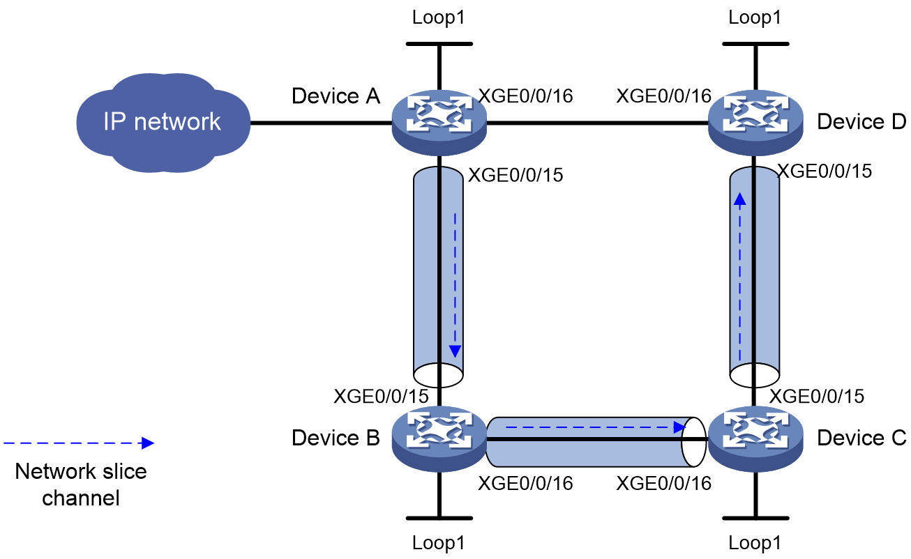
As shown in Figure 7, perform the following tasks on the devices to forward user packets through the network slice on Device A, Device B, Device C, and Device D:
· Configure Device A through Device D to run IS-IS to implement Layer 3 connectivity.
· Deploy an NSI on Device A through Device D. Configure a network slice channel on the output interfaces of Device A through Device D.
· Configure an SRv6 TE policy associated with the NSI to forward user packets along path Device A > Device B > Device C > Device D

|
Device |
Interface |
IP address |
Device |
Interface |
IP address |
|
Device A |
Loop1 |
1::1/128 |
Device B |
Loop1 |
2::2/128 |
|
|
XGE0/0/15 |
1000::1/64 |
|
XGE0/0/15 |
1000::2/64 |
|
|
XGE0/0/16 |
4000::1/64 |
|
XGE0/0/16 |
2000::2/64 |
|
Device C |
Loop1 |
3::3/128 |
Device D |
Loop1 |
4::4/128 |
|
|
XGE0/0/15 |
3000::3/64 |
|
XGE0/0/15 |
3000::4/64 |
|
|
XGE0/0/16 |
2000::3/64 |
|
XGE0/0/16 |
4000::4/64 |
Procedure
1. Configure IPv6 addresses and prefix lengths for the interfaces. (Details not shown.)
2. Configure Device A:
# Create NSI 1, specify the protocol number for the IPv6 hop-by-hop extension header, and enable network slice packet statistics.
<DeviceA> system-view
[DeviceA] network-slice
[DeviceA-network-slice] protocol-number 160
[DeviceA-network-slice] statistics enable
[DeviceA-network-slice] instance 1
[DeviceA-network-slice-instance-1] quit
# Configure a network slice channel on the interface.
[DeviceA] interface ten-gigabitethernet 0/0/15
[DeviceA-Ten-GigabitEthernet0/0/15] network-slice enable
[DeviceA-Ten-GigabitEthernet0/0/15-network-slice] slice-id 1 flex-channel 100
[DeviceA-Ten-GigabitEthernet0/0/15-network-slice] quit
[DeviceA-Ten-GigabitEthernet0/0/15] quit
# Specify the source address in the IPv6 header that the SRv6 VPN encapsulates into the IPv6 packets.
[DeviceA] segment-routing ipv6
[DeviceA-segment-routing-ipv6] encapsulation source-address 1::1
# Configure a locator and configure SRv6 End SIDs.
[DeviceA-segment-routing-ipv6] locator a ipv6-prefix 5000:: 64 static 32
[DeviceA-segment-routing-ipv6-locator-a] opcode 1 end no-flavor
[DeviceA-segment-routing-ipv6-locator-a] quit
# Specify a locator for the BSID of the SRv6 TE policy.
[DeviceA-segment-routing-ipv6] traffic-engineering
[DeviceA-srv6-te] srv6-policy locator a
# Configure an SID list.
[DeviceA-srv6-te] segment-list s1
[DeviceA-srv6-te-sl-s1] index 10 ipv6 6000::1
[DeviceA-srv6-te-sl-s1] index 20 ipv6 7000::1
[DeviceA-srv6-te-sl-s1] index 30 ipv6 8000::1
[DeviceA-srv6-te-sl-s1] quit
# Create SRv6 TE policy p1 and configure its attributes. Associate NSI 1 with SRv6 TE policy p1.
[DeviceA-srv6-te] policy p1
[DeviceA-srv6-te-policy-p1] binding-sid ipv6 5000::2
[DeviceA-srv6-te-policy-p1] color 10 end-point ipv6 4::4
[DeviceA-srv6-te-policy-p1] candidate-paths
[DeviceA-srv6-te-policy-p1-path] preference 10
[DeviceA-srv6-te-policy-p1-path-pref-10] network-slice 1
[DeviceA-srv6-te-policy-p1-path-pref-10] explicit segment-list s1
[DeviceA-srv6-te-policy-p1-path-pref-10] quit
[DeviceA-srv6-te-policy-p1-path] quit
[DeviceA-srv6-te-policy-p1] quit
[DeviceA-srv6-te] quit
[DeviceA-segment-routing-ipv6] quit
# Configure IS-IS and set the IS-IS cost style to wide.
[DeviceA] isis 1
[DeviceA-isis-1] network-entity 00.0000.0000.0001.00
[DeviceA-isis-1] cost-style wide
[DeviceA-isis-1] address-family ipv6 unicast
[DeviceA-isis-1-ipv6] segment-routing ipv6 locator a
[DeviceA-isis-1-ipv6] quit
[DeviceA-isis-1] quit
[DeviceA] interface ten-gigabitethernet 0/0/15
[DeviceA-Ten-GigabitEthernet0/0/15] isis ipv6 enable 1
[DeviceA-Ten-GigabitEthernet0/0/15] quit
[DeviceA] interface ten-gigabitethernet 0/0/16
[DeviceA-Ten-GigabitEthernet0/0/16] isis ipv6 enable 1
[DeviceA-Ten-GigabitEthernet0/0/16] quit
[DeviceA] interface loopback 1
[DeviceA-LoopBack1] isis ipv6 enable 1
[DeviceA-LoopBack1] quit
3. Configure Device B.
# Create NSI 1, specify the protocol number for the IPv6 hop-by-hop extension header, and enable network slice packet statistics.
<DeviceB> system-view
[DeviceB] network-slice
[DeviceB-network-slice] protocol-number 160
[DeviceB-network-slice] statistics enable
[DeviceB-network-slice] instance 1
[DeviceB-network-slice-instance-1] quit
# Configure a network slice channel on the interfaces.
[DeviceB] interface ten-gigabitethernet 0/0/15
[DeviceB-Ten-GigabitEthernet0/0/15] network-slice enable
[DeviceB-Ten-GigabitEthernet0/0/15-network-slice] slice-id 1 flex-channel 100
[DeviceB-Ten-GigabitEthernet0/0/15-network-slice] quit
[DeviceB-Ten-GigabitEthernet0/0/15] quit
[DeviceB] interface ten-gigabitethernet 0/0/16
[DeviceB-Ten-GigabitEthernet0/0/16] network-slice enable
[DeviceB-Ten-GigabitEthernet0/0/16-network-slice] slice-id 1 flex-channel 100
[DeviceB-Ten-GigabitEthernet0/0/16-network-slice] quit
[DeviceB-Ten-GigabitEthernet0/0/16] quit
# Specify the SRv6 End SID.
[DeviceB] segment-routing ipv6
[DeviceB-segment-routing-ipv6] locator b ipv6-prefix 6000:: 64 static 32
[DeviceB-segment-routing-ipv6-locator-b] opcode 1 end no-flavor
[DeviceB-segment-routing-ipv6-locator-b] quit
[DeviceB-segment-routing-ipv6] quit
# Configure IS-IS and set the IS-IS cost style to wide.
[DeviceB] isis 1
[DeviceB-isis-1] network-entity 00.0000.0000.0002.00
[DeviceB-isis-1] cost-style wide
[DeviceB-isis-1] address-family ipv6 unicast
[DeviceB-isis-1-ipv6] segment-routing ipv6 locator b
[DeviceB-isis-1-ipv6] quit
[DeviceB-isis-1] quit
[DeviceB] interface ten-gigabitethernet 0/0/15
[DeviceB-Ten-GigabitEthernet0/0/15] isis ipv6 enable 1
[DeviceB-Ten-GigabitEthernet0/0/15] quit
[DeviceB] interface ten-gigabitethernet 0/0/16
[DeviceB-Ten-GigabitEthernet0/0/16] isis ipv6 enable 1
[DeviceB-Ten-GigabitEthernet0/0/16] quit
[DeviceB] interface loopback 1
[DeviceB-LoopBack1] isis ipv6 enable 1
[DeviceB-LoopBack1] quit
4. Configure Device C.
# Create NSI 1, specify the protocol number for the IPv6 hop-by-hop extension header, and enable network slice packet statistics.
<DeviceC> system-view
[DeviceC] network-slice
[DeviceC-network-slice] protocol-number 160
[DeviceC-network-slice] statistics enable
[DeviceC-network-slice] instance 1
[DeviceC-network-slice-instance-1] quit
# Configure a network slice channel on the interfaces.
[DeviceC] interface ten-gigabitethernet 0/0/15
[DeviceC-Ten-GigabitEthernet0/0/15] network-slice enable
[DeviceC-Ten-GigabitEthernet0/0/15-network-slice] slice-id 1 flex-channel 100
[DeviceC-Ten-GigabitEthernet0/0/15-network-slice] quit
[DeviceC-Ten-GigabitEthernet0/0/15] quit
[DeviceC] interface ten-gigabitethernet 0/0/16
[DeviceC-Ten-GigabitEthernet0/0/16] network-slice enable
[DeviceC-Ten-GigabitEthernet0/0/16-network-slice] slice-id 1 flex-channel 100
[DeviceC-Ten-GigabitEthernet0/0/16-network-slice] quit
[DeviceC-Ten-GigabitEthernet0/0/16] quit
# Specify the SRv6 End SID.
[DeviceC] segment-routing ipv6
[DeviceC-segment-routing-ipv6] locator c ipv6-prefix 7000:: 64 static 32
[DeviceC-segment-routing-ipv6-locator-c] opcode 1 end no-flavor
[DeviceC-segment-routing-ipv6-locator-c] quit
[DeviceC-segment-routing-ipv6] quit
# Configure IS-IS and set the IS-IS cost style to wide.
[DeviceC] isis 1
[DeviceC-isis-1] network-entity 00.0000.0000.0003.00
[DeviceC-isis-1] cost-style wide
[DeviceC-isis-1] address-family ipv6 unicast
[DeviceC-isis-1-ipv6] segment-routing ipv6 locator c
[DeviceC-isis-1-ipv6] quit
[DeviceC-isis-1] quit
[DeviceC] interface ten-gigabitethernet 0/0/15
[DeviceC-Ten-GigabitEthernet0/0/15] isis ipv6 enable 1
[DeviceC-Ten-GigabitEthernet0/0/15] quit
[DeviceC] interface ten-gigabitethernet 0/0/16
[DeviceC-Ten-GigabitEthernet0/0/16] isis ipv6 enable 1
[DeviceC-Ten-GigabitEthernet0/0/16] quit
[DeviceC] interface loopback 1
[DeviceC-LoopBack1] isis ipv6 enable 1
[DeviceC-LoopBack1] quit
5. Configure Device D.
# Create NSI 1, specify the protocol number for the IPv6 hop-by-hop extension header, and enable network slice packet statistics.
<DeviceD> system-view
[DeviceD] network-slice
[DeviceD-network-slice] protocol-number 160
[DeviceD-network-slice] statistics enable
[DeviceD-network-slice] instance 1
[DeviceD-network-slice-instance-1] quit
# Configure a network slice channel on the interface.
[DeviceD] interface ten-gigabitethernet 0/0/15
[DeviceD-Ten-GigabitEthernet0/0/15] network-slice enable
[DeviceD-Ten-GigabitEthernet0/0/15-network-slice] slice-id 1 flex-channel 100
[DeviceD-Ten-GigabitEthernet0/0/15-network-slice] quit
[DeviceD-Ten-GigabitEthernet0/0/15] quit
# Specify the SRv6 End SID.
[DeviceD] segment-routing ipv6
[DeviceD-segment-routing-ipv6] locator d ipv6-prefix 8000:: 64 static 32
[DeviceD-segment-routing-ipv6-locator-d] opcode 1 end no-flavor
[DeviceD-segment-routing-ipv6-locator-d] quit
[DeviceD-segment-routing-ipv6] quit
# Configure IS-IS and set the IS-IS cost style to wide.
[DeviceD] isis 1
[DeviceD-isis-1] network-entity 00.0000.0000.0004.00
[DeviceD-isis-1] cost-style wide
[DeviceD-isis-1] address-family ipv6 unicast
[DeviceD-isis-1-ipv6] segment-routing ipv6 locator d
[DeviceD-isis-1-ipv6] quit
[DeviceD-isis-1] quit
[DeviceD] interface ten-gigabitethernet 0/0/15
[DeviceD-Ten-GigabitEthernet0/0/15] isis ipv6 enable 1
[DeviceD-Ten-GigabitEthernet0/0/15] quit
[DeviceD] interface ten-gigabitethernet 0/0/16
[DeviceD-Ten-GigabitEthernet0/0/16] isis ipv6 enable 1
[DeviceD-Ten-GigabitEthernet0/0/16] quit
[DeviceD] interface loopback 1
[DeviceD-LoopBack1] isis ipv6 enable 1
[DeviceD-LoopBack1] quit
Verifying the configuration
# Display SRv6 TE policy information on Device A.
<DeviceA> display segment-routing ipv6 te policy
Name/ID: p1/0
Color: 10
Endpoint: 4::4
...
Status: Up
...
Candidate paths:
Preference : 10
Network slice ID: 1
...
The output shows that the SRv6 TE policy is up. The device can forward packets through the NSI associated with the SRv6 TE policy.
# Display brief packet statistics for NSI 1.
<DeviceA> display network-slice statistics slice-id 1 interface ten-gigabitethernet 0/0/15
Network slice statistics
Interface : XGE0/0/15
Slice ID : 1
[total]
Pass: 42,430,945 packets, 7,298,122,540 bytes
Discard: 2,368,695,114 packets, 407,415,559,608 bytes
Last 50 seconds pass rate:
72,498 pps, 99,757,056 bps
Last 50 seconds discard rate:
4,048,135 pps, 5,570,233,752 bps
Last 5 seconds pass rate:
7298 pps, 99,757,056 bps
Last 5 seconds discard rate:
4148,135 pps, 5,570,233,752 bps
Example: Configuring SRv6 network slicing in the SRv6 TE policy scenario (source address slicing)
Network configuration
As shown in Figure 8, the devices use the source address slicing method to encapsulate an NSI ID in network slice packets. The service traffic of the network slice is forwarded by an SRv6 TE policy through the network slice channels on Device A, Device B, Device C, and Device D successively. Configure the following settings to meet the requirements:
· Run IS-IS among Device A through Device D for Layer 3 intercommunication.
· Deploy a network slice instance on Device A through Device D, and configure network slice channels on the egress interfaces for packet forwarding.
· On Device A, configure an SRv6 TE policy, associate it with the network slice instance, and restrict the forwarding path of user traffic as Device A -> Device B -> Device C -> Device D.
· On Device A through Device D, enable the feature of carrying an NSI ID in the IPv6 source address and configure an IPv6 source address prefix for NSI ID encapsulation. On the source node of the SRv6 TE policy (Device A), use IS-IS to advertise the IPv6 source address prefix to other devices.
|
Device |
Interface |
IP address |
Device |
Interface |
IP address |
|
Device A |
Loop1 |
1::1/128 |
Device B |
Loop1 |
2::2/128 |
|
|
XGE0/0/15 |
1000::1/64 |
|
XGE0/0/15 |
1000::2/64 |
|
|
XGE0/0/16 |
4000::1/64 |
|
XGE0/0/16 |
2000::2/64 |
|
Device C |
Loop1 |
3::3/128 |
Device D |
Loop1 |
4::4/128 |
|
|
XGE0/0/15 |
3000::3/64 |
|
XGE0/0/15 |
3000::4/64 |
|
|
XGE0/0/16 |
2000::3/64 |
|
XGE0/0/16 |
4000::4/64 |
Procedure
1. Configure IPv6 addresses and prefix lengths for the interfaces. (Details not shown.)
2. Configure Device A:
# Enable the feature of carrying an NSI ID in the IPv6 source address, and enable packet statistics for network slices, and create an NSI.
<DeviceA> system-view
[DeviceA] network-slice
[DeviceA-network-slice] slice-encapsulation ipv6-source
[DeviceA-network-slice] statistics enable
[DeviceA-network-slice] instance 1
[DeviceA-network-slice-instance-1] quit
# Enter slice prefix view and configure an IPv6 source address prefix for NSI ID encapsulation.
[DeviceA-network-slice] slice-prefix
[DeviceA-network-slice-prefix] index 1 prefix-name SrcPrefix1 ipv6-prefix 1001:0:1:1:: common-length 48 prefix-length 64
[DeviceA-network-slice-prefix] quit
[DeviceA-network-slice] quit
# Configure IS-IS to advertise the IPv6 source address prefix.
[DeviceA] isis 1
[DeviceA-isis-1] address-family ipv6
[DeviceA-isis-1-ipv6] advertise slice-prefix-route
[DeviceA-isis-1-ipv6] quit
[DeviceA-isis-1] quit
# Configure network slice channels on the forwarding output interfaces.
[DeviceA] interface ten-gigabitethernet 0/0/15
[DeviceA-Ten-GigabitEthernet0/0/15] network-slice enable
[DeviceA-Ten-GigabitEthernet0/0/15-network-slice] slice-id 1 flex-channel 100
[DeviceA-Ten-GigabitEthernet0/0/15-network-slice] quit
[DeviceA-Ten-GigabitEthernet0/0/15] quit
# Configure the source address of the IPv6 packet header encapsulated by SRv6 VPN.
[DeviceA] segment-routing ipv6
[DeviceA-segment-routing-ipv6] encapsulation source-address 1::1
# Configure an SRv6 SID locator, and statically configure an End-type SRv6 SID.
[DeviceA-segment-routing-ipv6] locator a ipv6-prefix 5000:: 96 static 16
[DeviceA-segment-routing-ipv6-locator-a] opcode 1 end no-flavor
[DeviceA-segment-routing-ipv6-locator-a] quit
# Apply the locator to the BSID of the SRv6 TE policy.
[DeviceA-segment-routing-ipv6] traffic-engineering
[DeviceA-srv6-te] srv6-policy locator a
# Configure an SID list.
[DeviceA-srv6-te] segment-list s1
[DeviceA-srv6-te-sl-s1] index 10 ipv6 6000::1
[DeviceA-srv6-te-sl-s1] index 20 ipv6 7000::1
[DeviceA-srv6-te-sl-s1] index 30 ipv6 8000::1
[DeviceA-srv6-te-sl-s1] quit
# Create an SRv6 TE policy, configure SRv6 TE policy attributes, and associate the policy with the network slice instance.
[DeviceA-srv6-te] policy p1
[DeviceA-srv6-te-policy-p1] binding-sid ipv6 5000::2
[DeviceA-srv6-te-policy-p1] color 10 end-point ipv6 4::4
[DeviceA-srv6-te-policy-p1] candidate-paths
[DeviceA-srv6-te-policy-p1-path] preference 10
[DeviceA-srv6-te-policy-p1-path-pref-10] network-slice 1 slice-prefix SrcPrefix1
[DeviceA-srv6-te-policy-p1-path-pref-10] explicit segment-list s1
[DeviceA-srv6-te-policy-p1-path-pref-10] quit
[DeviceA-srv6-te-policy-p1-path] quit
[DeviceA-srv6-te-policy-p1] quit
[DeviceA-srv6-te] quit
[DeviceA-segment-routing-ipv6] quit
# Configure IS-IS to ensure network layer intercommunication and set the cost style to wide.
[DeviceA] isis 1
[DeviceA-isis-1] network-entity 00.0000.0000.0001.00
[DeviceA-isis-1] cost-style wide
[DeviceA-isis-1] address-family ipv6 unicast
[DeviceA-isis-1-ipv6] segment-routing ipv6 locator a
[DeviceA-isis-1-ipv6] quit
[DeviceA-isis-1] quit
[DeviceA] interface ten-gigabitethernet 0/0/15
[DeviceA-Ten-GigabitEthernet0/0/15] isis ipv6 enable 1
[DeviceA-Ten-GigabitEthernet0/0/15] quit
[DeviceA] interface ten-gigabitethernet 0/0/16
[DeviceA-Ten-GigabitEthernet0/0/16] isis ipv6 enable 1
[DeviceA-Ten-GigabitEthernet0/0/16] quit
[DeviceA] interface loopback 1
[DeviceA-LoopBack1] isis ipv6 enable 1
[DeviceA-LoopBack1] quit
3. Configure Device B:
# Enable the feature of carrying an NSI ID in the IPv6 source address, and enable packet statistics for network slices, and create an NSI.
<DeviceB> system-view
[DeviceB] network-slice
[DeviceB-network-slice] slice-encapsulation ipv6-source
[DeviceB-network-slice] statistics enable
[DeviceB-network-slice] instance 1
[DeviceB-network-slice-instance-1] quit
# Enter slice prefix view and configure an IPv6 source address prefix for NSI ID encapsulation.
[DeviceB-network-slice] slice-prefix
[DeviceB-network-slice-prefix] index 1 prefix-name SrcPrefix2 ipv6-prefix 1001:0:1:2:: common-length 48 prefix-length 64
[DeviceB-network-slice-prefix] quit
[DeviceB-network-slice] quit
# Configure IS-IS to advertise the IPv6 source address prefix.
[DeviceB] isis 1
[DeviceB-isis-1] address-family ipv6
[DeviceB-isis-1-ipv6] advertise slice-prefix-route
[DeviceB-isis-1-ipv6] quit
[DeviceB-isis-1] quit
# Configure network slice channels on the forwarding output interfaces.
[DeviceB] interface ten-gigabitethernet 0/0/15
[DeviceB-Ten-GigabitEthernet0/0/15] network-slice enable
[DeviceB-Ten-GigabitEthernet0/0/15-network-slice] slice-id 1 flex-channel 100
[DeviceB-Ten-GigabitEthernet0/0/15-network-slice] quit
[DeviceB-Ten-GigabitEthernet0/0/15] quit
[DeviceB] interface ten-gigabitethernet 0/0/16
[DeviceB-Ten-GigabitEthernet0/0/16] network-slice enable
[DeviceB-Ten-GigabitEthernet0/0/16-network-slice] slice-id 1 flex-channel 100
[DeviceB-Ten-GigabitEthernet0/0/16-network-slice] quit
[DeviceB-Ten-GigabitEthernet0/0/16] quit
# Configure an SRv6 End SID.
[DeviceB] segment-routing ipv6
[DeviceB-segment-routing-ipv6] locator b ipv6-prefix 6000:: 96 static 16
[DeviceB-segment-routing-ipv6-locator-b] opcode 1 end no-flavor
[DeviceB-segment-routing-ipv6-locator-b] quit
[DeviceB-segment-routing-ipv6] quit
# Configure IS-IS to ensure network layer intercommunication and set the cost style to wide.
[DeviceB] isis 1
[DeviceB-isis-1] network-entity 00.0000.0000.0002.00
[DeviceB-isis-1] cost-style wide
[DeviceB-isis-1] address-family ipv6 unicast
[DeviceB-isis-1-ipv6] segment-routing ipv6 locator b
[DeviceB-isis-1-ipv6] quit
[DeviceB-isis-1] quit
[DeviceB] interface ten-gigabitethernet 0/0/15
[DeviceB-Ten-GigabitEthernet0/0/15] isis ipv6 enable 1
[DeviceB-Ten-GigabitEthernet0/0/15] quit
[DeviceB] interface ten-gigabitethernet 0/0/16
[DeviceB-Ten-GigabitEthernet0/0/16] isis ipv6 enable 1
[DeviceB-Ten-GigabitEthernet0/0/16] quit
[DeviceB] interface loopback 1
[DeviceB-LoopBack1] isis ipv6 enable 1
[DeviceB-LoopBack1] quit
4. Configure Device C:
# Enable the feature of carrying an NSI ID in the IPv6 source address, and enable packet statistics for network slices, and create an NSI.
<DeviceC> system-view
[DeviceC] network-slice
[DeviceC-network-slice] slice-encapsulation ipv6-source
[DeviceC-network-slice] statistics enable
[DeviceC-network-slice] instance 1
[DeviceC-network-slice-instance-1] quit
# Enter slice prefix view and configure an IPv6 source address prefix for NSI ID encapsulation.
[DeviceC-network-slice] slice-prefix
[DeviceC-network-slice-prefix] index 1 prefix-name SrcPrefix3 ipv6-prefix 1001:0:1:3:: common-length 48 prefix-length 64
[DeviceC-network-slice-prefix] quit
[DeviceC-network-slice] quit
# Configure IS-IS to advertise the IPv6 source address prefix.
[DeviceC] isis 1
[DeviceC-isis-1] address-family ipv6
[DeviceC-isis-1-ipv6] advertise slice-prefix-route
[DeviceC-isis-1-ipv6] quit
[DeviceC-isis-1] quit
# Configure network slice channels on the forwarding output interfaces.
[DeviceC] interface ten-gigabitethernet 0/0/15
[DeviceC-Ten-GigabitEthernet0/0/15] network-slice enable
[DeviceC-Ten-GigabitEthernet0/0/15-network-slice] slice-id 1 flex-channel 100
[DeviceC-Ten-GigabitEthernet0/0/15-network-slice] quit
[DeviceC-Ten-GigabitEthernet0/0/15] quit
[DeviceC] interface ten-gigabitethernet 0/0/16
[DeviceC-Ten-GigabitEthernet0/0/16] network-slice enable
[DeviceC-Ten-GigabitEthernet0/0/16-network-slice] slice-id 1 flex-channel 100
[DeviceC-Ten-GigabitEthernet0/0/16-network-slice] quit
[DeviceC-Ten-GigabitEthernet0/0/16] quit
# Configure an SRv6 End SID.
[DeviceC] segment-routing ipv6
[DeviceC-segment-routing-ipv6] locator c ipv6-prefix 7000:: 96 static 16
[DeviceC-segment-routing-ipv6-locator-c] opcode 1 end no-flavor
[DeviceC-segment-routing-ipv6-locator-c] quit
[DeviceC-segment-routing-ipv6] quit
# Configure IS-IS to ensure network layer intercommunication and set the cost style to wide.
[DeviceC] isis 1
[DeviceC-isis-1] network-entity 00.0000.0000.0003.00
[DeviceC-isis-1] cost-style wide
[DeviceC-isis-1] address-family ipv6 unicast
[DeviceC-isis-1-ipv6] segment-routing ipv6 locator c
[DeviceC-isis-1-ipv6] quit
[DeviceC-isis-1] quit
[DeviceC] interface ten-gigabitethernet 0/0/15
[DeviceC-Ten-GigabitEthernet0/0/15] isis ipv6 enable 1
[DeviceC-Ten-GigabitEthernet0/0/15] quit
[DeviceC] interface ten-gigabitethernet 0/0/16
[DeviceC-Ten-GigabitEthernet0/0/16] isis ipv6 enable 1
[DeviceC-Ten-GigabitEthernet0/0/16] quit
[DeviceC] interface loopback 1
[DeviceC-LoopBack1] isis ipv6 enable 1
[DeviceC-LoopBack1] quit
5. Configure Device D:
# Enable the feature of carrying an NSI ID in the IPv6 source address, and enable packet statistics for network slices, and create an NSI.
<DeviceD> system-view
[DeviceD] network-slice
[DeviceD-network-slice] slice-encapsulation ipv6-source
[DeviceD-network-slice] statistics enable
[DeviceD-network-slice] instance 1
[DeviceD-network-slice-instance-1] quit
# Enter slice prefix view and configure an IPv6 source address prefix for NSI ID encapsulation.
[DeviceD-network-slice] slice-prefix
[DeviceD-network-slice-prefix] index 1 prefix-name SrcPrefix4 ipv6-prefix 1001:0:1:4:: common-length 48 prefix-length 64
[DeviceD-network-slice-prefix] quit
[DeviceD-network-slice] quit
# Configure IS-IS to advertise the IPv6 source address prefix.
[DeviceD] isis 1
[DeviceD-isis-1] address-family ipv6
[DeviceD-isis-1-ipv6] advertise slice-prefix-route
[DeviceD-isis-1-ipv6] quit
[DeviceD-isis-1] quit
# Configure a network slice channel on the forwarding output interface.
[DeviceD] interface ten-gigabitethernet 0/0/15
[DeviceD-Ten-GigabitEthernet0/0/15] network-slice enable
[DeviceD-Ten-GigabitEthernet0/0/15-network-slice] slice-id 1 flex-channel 100
[DeviceD-Ten-GigabitEthernet0/0/15-network-slice] quit
[DeviceD-Ten-GigabitEthernet0/0/15] quit
# Configure an SRv6 End SID.
[DeviceD] segment-routing ipv6
[DeviceD-segment-routing-ipv6] locator d ipv6-prefix 8000:: 96 static 16
[DeviceD-segment-routing-ipv6-locator-d] opcode 1 end no-flavor
[DeviceD-segment-routing-ipv6-locator-d] quit
[DeviceD-segment-routing-ipv6] quit
# Configure IS-IS to ensure network layer intercommunication and set the cost style to wide.
[DeviceD] isis 1
[DeviceD-isis-1] network-entity 00.0000.0000.0004.00
[DeviceD-isis-1] cost-style wide
[DeviceD-isis-1] address-family ipv6 unicast
[DeviceD-isis-1-ipv6] segment-routing ipv6 locator d
[DeviceD-isis-1-ipv6] quit
[DeviceD-isis-1] quit
[DeviceD] interface ten-gigabitethernet 0/0/15
[DeviceD-Ten-GigabitEthernet0/0/15] isis ipv6 enable 1
[DeviceD-Ten-GigabitEthernet0/0/15] quit
[DeviceD] interface ten-gigabitethernet 0/0/16
[DeviceD-Ten-GigabitEthernet0/0/16] isis ipv6 enable 1
[DeviceD-Ten-GigabitEthernet0/0/16] quit
[DeviceD] interface loopback 1
[DeviceD-LoopBack1] isis ipv6 enable 1
[DeviceD-LoopBack1] quit
Verifying the configuration
# On Device A, display SRv6 TE policy information. Verify that the SRv6 TE policy is in up state and the device can forward traffic through the NSI associated with the SRv6 TE policy.
<DeviceA> display segment-routing ipv6 te policy
Name/ID: p1/0
Color: 10
Endpoint: 4::4
...
Status: Up
...
Candidate paths:
Preference : 10
Network slice ID: 1
...
# Display brief packet statistics for the NSI with ID 1.
<DeviceA> display network-slice statistics slice-id 1 interface ten-gigabitethernet 0/0/15
Network slice statistics
Interface : XGE0/0/15
Slice ID : 1
[total]
Pass: 42,430,945 packets, 7,298,122,540 bytes
Discard: 2,368,695,114 packets, 407,415,559,608 bytes
Last 50 seconds pass rate:
72,498 pps, 99,757,056 bps
Last 50 seconds discard rate:
4,048,135 pps, 5,570,233,752 bps
Last 5 seconds pass rate:
7298 pps, 99,757,056 bps
Last 5 seconds discard rate:
4148,135 pps, 5,570,233,752 bps
Example: Configuring SRv6 network slicing in the IPv4 L3VPN over SRv6 BE scenario (HBH slicing)
Network configuration
As shown in Figure 9, the SRv6 network contains NSI 1 and NSI 2. The slicing interfaces on PE 1, P, and PE 2 contain network slice channel 1 and network slice channel 2 that are associated with NSI 1 and NSI 2, respectively. In VPN instance vpna, an SRv6 BE tunnel carries traffic between CE 1 and CE 2, and it is associated with NSI 1.
To meet the network configuration requirements, perform the following tasks:
· Run IS-IS among PE 1, P, and PE 2 for Layer 3 connectivity. Configure the PEs and CEs to use EBGP to exchange VPN routes.
· Configure PE 1 and PE 2 to establish an MP-BGP peer relationship and exchange VPNv4 routes that include the color extended community attribute.
· Deploy an NSI on PE 1, P, and PE 2 and create network slice channels on the output interfaces for forwarding network slice packets.
· Create a mapping between the color extended community attribute and NSI on PE 1 and PE 2.
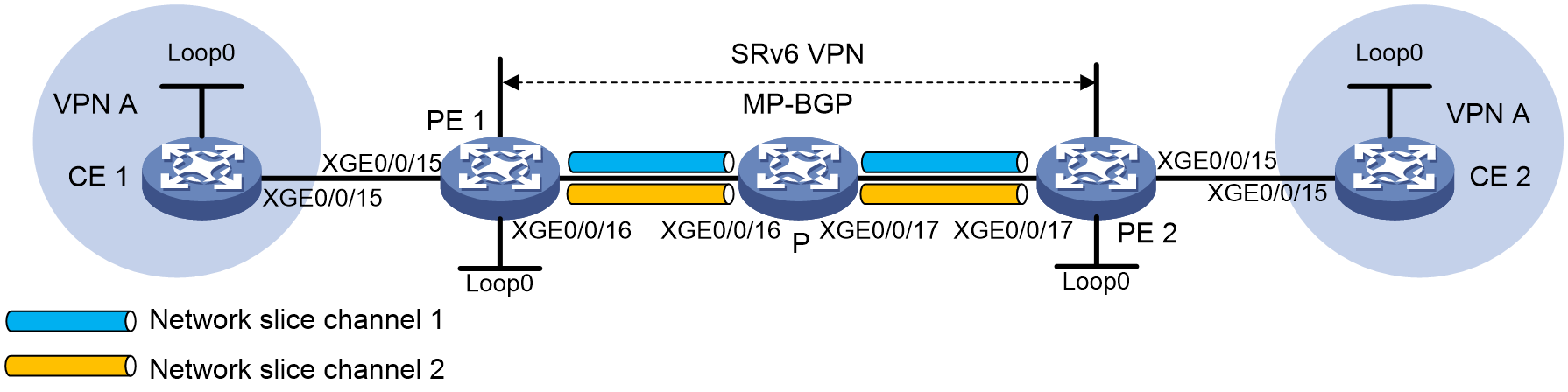
|
Device |
Interface |
IP address |
Device |
Interface |
IP address |
|
CE 1 |
Loop0 |
1.1.1.1/32 |
PE 2 |
Loop0 |
4::4/128 |
|
|
XGE0/0/15 |
10.1.1.2/24 |
|
XGE0/0/15 |
10.2.1.1/24 |
|
CE 2 |
Loop0 |
2.2.2.2/32 |
|
XGE0/0/17 |
2000::2/96 |
|
|
XGE0/0/15 |
10.2.1.2/24 |
P |
Loop0 |
5::5/128 |
|
PE 1 |
Loop0 |
3::3/128 |
|
XGE0/0/16 |
1000::2/96 |
|
|
XGE0/0/15 |
10.1.1.1/24 |
|
XGE0/0/17 |
2000::1/96 |
|
|
XGE0/0/16 |
1000::1/96 |
|
|
|
Procedure
1. On PE 1, PE 2, and P, configure IPv6 IS-IS for communication among the devices in the backbone network:
# Configure PE 1.
<PE1> system-view
[PE1] isis 1
[PE1-isis-1] is-level level-1
[PE1-isis-1] cost-style wide
[PE1-isis-1] network-entity 10.1111.1111.1111.00
[PE1-isis-1] address-family ipv6 unicast
[PE1-isis-1-ipv6] quit
[PE1-isis-1] quit
[PE1] interface loopback 0
[PE1-LoopBack0] ipv6 address 3::3 128
[PE1-LoopBack0] isis ipv6 enable 1
[PE1-LoopBack0] quit
[PE1] interface ten-gigabitethernet 0/0/16
[PE1-Ten-GigabitEthernet0/0/16] ipv6 address 1000::1 96
[PE1-Ten-GigabitEthernet0/0/16] isis ipv6 enable
[PE1-Ten-GigabitEthernet0/0/16] quit
# Configure P.
<P> system-view
[P] isis
[P-isis-1] is-level level-1
[P-isis-1] cost-style wide
[P-isis-1] network-entity 10.2222.2222.2222.00
[P-isis-1] address-family ipv6 unicast
[P-isis-1-ipv6] quit
[P-isis-1] quit
[P] interface loopback 0
[P-LoopBack0] ipv6 address 5::5 128
[P-LoopBack0] isis ipv6 enable
[P-LoopBack0] quit
[P] interface ten-gigabitethernet 0/0/16
[P-Ten-GigabitEthernet0/0/16] ipv6 address 1000::2 96
[P-Ten-GigabitEthernet0/0/16] isis ipv6 enable
[P-Ten-GigabitEthernet0/0/16] quit
[P] interface ten-gigabitethernet 0/0/17
[P-Ten-GigabitEthernet0/0/17] ipv6 address 2000::1 96
[P-Ten-GigabitEthernet0/0/17] isis ipv6 enable
[P-Ten-GigabitEthernet0/0/17] quit
# Configure PE 2.
<PE2> system-view
[PE2] isis
[PE2-isis-1] is-level level-1
[PE2-isis-1] cost-style wide
[PE2-isis-1] network-entity 10.3333.3333.3333.00
[PE2-isis-1] address-family ipv6 unicast
[PE2-isis-1-ipv6] quit
[PE2-isis-1] quit
[PE2] interface loopback 0
[PE2-LoopBack0] ipv6 address 4::4 128
[PE2-LoopBack0] isis ipv6 enable
[PE2-LoopBack0] quit
[PE2] interface ten-gigabitethernet 0/0/17
[PE2-Ten-GigabitEthernet0/0/17] ipv6 address 2000::2 96
[PE2-Ten-GigabitEthernet0/0/17] isis ipv6 enable
[PE2-Ten-GigabitEthernet0/0/17] quit
# Verify that PE 1, P, and PE 2 can establish IPv6 IS-IS neighbor relationships.
¡ Execute the display isis peer command to verify that the neighbors are in up state.
¡ Execute the display isis route ipv6 command to verify that each PE has learned the route of Loopback 0 from the other PE.
2. Configure VPN instance vpna on the PEs, and connect the CE to the PE at each site:
# Configure PE 1.
[PE1] ip vpn-instance vpna
[PE1-vpn-instance-vpna] route-distinguisher 100:1
[PE1-vpn-instance-vpna] vpn-target 111:1
[PE1-vpn-instance-vpna] quit
[PE1] interface ten-gigabitethernet 0/0/15
[PE1-Ten-GigabitEthernet0/0/15] ip binding vpn-instance vpna
[PE1-Ten-GigabitEthernet0/0/15] ip address 10.1.1.1 24
[PE1-Ten-GigabitEthernet0/0/15] quit
# Configure PE 2.
[PE2] ip vpn-instance vpna
[PE2-vpn-instance-vpna] route-distinguisher 100:1
[PE2-vpn-instance-vpna] vpn-target 111:1
[PE2-vpn-instance-vpna] quit
[PE2] interface ten-gigabitethernet 0/0/15
[PE2-Ten-GigabitEthernet0/0/15] ip binding vpn-instance vpna
[PE2-Ten-GigabitEthernet0/0/15] ip address 10.2.1.1 24
[PE2-Ten-GigabitEthernet0/0/15] quit
# Configure IP addresses for interfaces on the CEs, as shown in Figure 9. (Details not shown.)
3. Establish a EBGP peer relationship between the PE and CE at each site and import VPN routes:
# Configure CE 1.
<CE1> system-view
[CE1] bgp 65410
[CE1-bgp-default] peer 10.1.1.1 as-number 100
[CE1-bgp-default] address-family ipv4 unicast
[CE1-bgp-default-ipv4] peer 10.1.1.1 enable
[CE1-bgp-default-ipv4] import-route direct
[CE1-bgp-default-ipv4] network 1.1.1.1 255.255.255.255
[CE1-bgp-default-ipv4] quit
[CE1-bgp-default] quit
# Configure CE 2 in the same way CE 1 is configured. (Details not shown.)
# Configure PE 1.
[PE1] bgp 100
[PE1-bgp-default] router-id 1.1.1.1
[PE1-bgp-default] ip vpn-instance vpna
[PE1-bgp-default-vpna] peer 10.1.1.2 as-number 65410
[PE1-bgp-default-vpna] address-family ipv4 unicast
[PE1-bgp-default-ipv4-vpna] peer 10.1.1.2 enable
[PE1-bgp-default-ipv4-vpna] quit
[PE1-bgp-default-vpna] quit
# Configure PE 2 in the same way PE 1 is configured. (Details not shown.)
# On each PE, execute the display bgp peer ipv4 vpn-instance command to verify that the PE and CE at each site have established a BGP peer relationship and the relationship is in Established state.
4. On each PE, create an IPv4 prefix list, and configure a routing policy to apply the color extended community attribute to BGP routes that match the IPv4 prefix list:
# Configure PE 1.
[PE1] ip prefix-list p1 permit 1.1.1.1 32
[PE1] route-policy color permit node 10
[PE1-route-policy-color-10] if-match ip address prefix-list p1
[PE1-route-policy-color-10] apply extcommunity color 00:10
[PE1-route-policy-color-10] quit
# Configure PE 2.
[PE2] ip prefix-list p1 permit 2.2.2.2 32
[PE2] route-policy color permit node 10
[PE2-route-policy-color-10] if-match ip address prefix-list p1
[PE2-route-policy-color-10] apply extcommunity color 00:10
[PE2-route-policy-color-10] quit
5. Establish an MP-IBGP peer relationship between the PEs, and configure the PEs to exchange VPNv4 routes that include the color extended community attribute:
# Configure PE 1.
[PE1] bgp 100
[PE1-bgp-default] peer 4::4 as-number 100
[PE1-bgp-default] peer 4::4 connect-interface loopback 0
[PE1-bgp-default] address-family vpnv4
[PE1-bgp-default-vpnv4] peer 4::4 enable
[PE1-bgp-default-vpnv4] peer 4::4 route-policy color export
[PE1-bgp-default-vpnv4] quit
[PE1-bgp-default] quit
# Configure PE 2.
[PE2] bgp 100
[PE2-bgp-default] peer 3::3 as-number 100
[PE2-bgp-default] peer 3::3 connect-interface loopback 0
[PE2-bgp-default] address-family vpnv4
[PE2-bgp-default-vpnv4] peer 3::3 enable
[PE2-bgp-default-vpnv4] peer 3::3 route-policy color export
[PE2-bgp-default-vpnv4] quit
[PE2-bgp-default] quit
# On each PE, execute the display bgp peer vpnv4 command to verify that the PEs have established a BGP peer relationship and the relationship is in Established state.
6. On each PE, specify a source address for the outer IPv6 header of SRv6 packets in the IP L3VPN over SRv6 network:
# Configure PE 1.
[PE1] segment-routing ipv6
[PE1-segment-routing-ipv6] encapsulation source-address 3::3
# Configure PE 2.
[PE2] segment-routing ipv6
[PE2-segment-routing-ipv6] encapsulation source-address 4::4
7. On each PE, specify a destination End.DT4 SID for the outer IPv6 header of SRv6 packets in the IP L3VPN over SRv6 network:
# Configure PE 1.
[PE1-segment-routing-ipv6] locator aaa ipv6-prefix 100::1:0 96 static 8
[PE1-segment-routing-ipv6-locator-aaa] quit
[PE1-segment-routing-ipv6] quit
[PE1] isis 1
[PE1-isis-1] address-family ipv6 unicast
[PE1-isis-1-ipv6] segment-routing ipv6 locator aaa
[PE1-isis-1-ipv6] quit
[PE1-isis-1] quit
# Configure PE 2.
[PE2-segment-routing-ipv6] locator bbb ipv6-prefix 200::1:0 96 static 8
[PE2-segment-routing-ipv6-locator-bbb] quit
[PE2-segment-routing-ipv6] quit
[PE2] isis 1
[PE2-isis-1] address-family ipv6 unicast
[PE2-isis-1-ipv6] segment-routing ipv6 locator bbb
[PE2-isis-1-ipv6] quit
[PE2-isis-1] quit
# On each PE, execute the display ipv6 routing-table command to verify that the End.DT4 SID has been imported to the routing table and an SRv6 route has been generated.
8. On each PE, add the End.DT4 SID to private routes:
# Configure PE 1.
[PE1] bgp 100
[PE1-bgp-default] ip vpn-instance vpna
[PE1-bgp-default-vpna] address-family ipv4 unicast
[PE1-bgp-default-ipv4-vpna] segment-routing ipv6 locator aaa
[PE1-bgp-default-ipv4-vpna] quit
[PE1-bgp-default-vpna] quit
[PE1-bgp-default] quit
# Configure PE 2.
[PE2] bgp 100
[PE2-bgp-default] ip vpn-instance vpna
[PE2-bgp-default-vpna] address-family ipv4 unicast
[PE2-bgp-default-ipv4-vpna] segment-routing ipv6 locator bbb
[PE2-bgp-default-ipv4-vpna] quit
[PE2-bgp-default-vpna] quit
[PE2-bgp-default] quit
9. On each PE, configure IPv6 peers to exchange End.DT4 SIDs and allow private routes to recurse to End.DT4 SID routes:
# Configure PE 1.
[PE1] bgp 100
[PE1-bgp-default] address-family vpnv4
[PE1-bgp-default-vpnv4] peer 4::4 prefix-sid
[PE1-bgp-default-vpnv4] quit
[PE1-bgp-default] ip vpn-instance vpna
[PE1-bgp-default-vpna] address-family ipv4 unicast
[PE1-bgp-default-ipv4-vpna] segment-routing ipv6 best-effort
[PE1-bgp-default-ipv4-vpna] quit
[PE1-bgp-default-vpna] quit
[PE1-bgp-default] quit
# Configure PE 2.
[PE2] bgp 100
[PE2-bgp-default] address-family vpnv4
[PE2-bgp-default-vpnv4] peer 3::3 prefix-sid
[PE2-bgp-default-vpnv4] quit
[PE2-bgp-default] ip vpn-instance vpna
[PE2-bgp-default-vpna] address-family ipv4 unicast
[PE2-bgp-default-ipv4-vpna] segment-routing ipv6 best-effort
[PE2-bgp-default-ipv4-vpna] quit
[PE2-bgp-default-vpna] quit
[PE2-bgp-default] quit
# On each PE, execute the display bgp routing-table vpnv4 command to display detailed information about the routes advertised by the remote PE. Verify that the routes have SID attribute data.
10. On PE 1, P, and PE 2, configure NSIs, configure the protocol number for the IPv6 hop-by-hop extension header, and enable statistics for network slice packets:
# Configure PE 1.
[PE1] network-slice
[PE1-network-slice] protocol-number 160
[PE1-network-slice] statistics enable
[PE1-network-slice] instance 1
[PE1-network-slice-instance-1] quit
[PE1-network-slice] instance 2
[PE1-network-slice-instance-2] quit
[PE1-network-slice] instance 10
[PE1-network-slice-instance-10] quit
# Configure P and PE 2 in the same way PE 1 is configured. (Details not shown.)
11. On PE 1, P, and PE 2, configure a main interface as a base interface, configure the subinterfaces of the main interface as slicing interfaces, and create network slice channels on the slicing interfaces:
# Configure PE 1.
[PE1] interface ten-gigabitethernet 0/0/16
[PE1-Ten-GigabitEthernet0/0/16] network-slice enable
[PE1-Ten-GigabitEthernet0/0/16-network-slice] slice-id 10 data-plane
[PE1-Ten-GigabitEthernet0/0/16-network-slice] quit
[PE1-Ten-GigabitEthernet0/0/16] quit
[PE1] interface ten-gigabitethernet 0/0/16.1
[PE1-Ten-GigabitEthernet0/0/16.1] network-slice enable
[PE1-Ten-GigabitEthernet0/0/16.1-network-slice] basic slice-id 10
[PE1-Ten-GigabitEthernet0/0/16.1-network-slice] slice-id 1 flex-channel 100
[PE1-Ten-GigabitEthernet0/0/16.1-network-slice] quit
[PE1-Ten-GigabitEthernet0/0/16.1] quit
[PE1] interface ten-gigabitethernet 0/0/16.2
[PE1-Ten-GigabitEthernet0/0/16.2] network-slice enable
[PE1-Ten-GigabitEthernet0/0/16.2-network-slice] basic slice-id 10
[PE1-Ten-GigabitEthernet0/0/16.2-network-slice] slice-id 2 flex-channel 100
[PE1-Ten-GigabitEthernet0/0/16.2-network-slice] quit
[PE1-Ten-GigabitEthernet0/0/16.2] quit
# Configure P and PE 2 in the same way PE 1 is configured. (Details not shown.)
# On the devices, execute the display network-slice binding-list command to display NSI and interface associations.
12. On each PE, configure a mapping between NSI 1 and color 10:
# Configure PE 1.
[PE1] network-slice
[PE1-network-slice] network-slice color-mapping
[PE1-network-slice-color-mapping] color 10 network-slice 1
[PE1-network-slice-color-mapping] quit
[PE1-network-slice] quit
# Configure PE 2 in the same way PE 1 is configured. (Details not shown.)
# On each PE, execute the display network-slice color-mapping command to display NSI and color mappings.
Verifying the configuration
# On each PE, display routes destined for the remote CE. Verify that the next hop of the routes is the End.DT4 SID of the routes.
This step uses PE 1 as an example.
<PE1> display ip routing-table vpn-instance vpna
Destinations : 12 Routes : 12
Destination/Mask Proto Pre Cost NextHop Interface
0.0.0.0/32 Direct 0 0 127.0.0.1 InLoop0
10.1.1.0/24 Direct 0 0 10.1.1.1 XGE0/0/15
10.1.1.0/32 Direct 0 0 10.1.1.1 XGE0/0/15
10.1.1.1/32 Direct 0 0 127.0.0.1 InLoop0
10.1.1.255/32 Direct 0 0 10.1.1.1 XGE0/0/15
10.2.1.0/24 BGP 255 0 200::1:0 XGE0/0/16
2.2.2.2/32 BGP 255 0 200::1:0 XGE0/0/16
127.0.0.0/8 Direct 0 0 127.0.0.1 InLoop0
127.0.0.0/32 Direct 0 0 127.0.0.1 InLoop0
127.0.0.1/32 Direct 0 0 127.0.0.1 InLoop0
127.255.255.255/32 Direct 0 0 127.0.0.1 InLoop0
255.255.255.255/32 Direct 0 0 127.0.0.1 InLoop0
# Verify that CE 1 and CE 2 can ping each other. (Details not shown.)
# Display brief packet statistics for NSI 1.
<PE1> display network-slice statistics slice-id 1 interface ten-gigabitethernet 0/0/16.1
Network slice statistics
Interface : XGE0/0/16.1
Slice ID : 1
[total]
Pass: 42,430,945 packets, 7,298,122,540 bytes
Discard: 2,368,695,114 packets, 407,415,559,608 bytes
Last 50 seconds pass rate:
72,498 pps, 99,757,056 bps
Last 50 seconds discard rate:
4,048,135 pps, 5,570,233,752 bps
Last 5 seconds pass rate:
7298 pps, 99,757,056 bps
Last 5 seconds discard rate:
4148,135 pps, 5,570,233,752 bps
