- Table of Contents
-
- 10-Segment Routing Configuration Guide
- 00-Preface
- 01-SR-MPLS configuration
- 02-SR-MPLS TE policy configuration
- 03-SRv6 configuration
- 04-SRv6 TE policy configuration
- 05-SRv6 VPN overview
- 06-IP L3VPN over SRv6 configuration
- 07-EVPN L3VPN over SRv6 configuration
- 08-EVPN VPWS over SRv6 configuration
- 09-EVPN VPLS over SRv6 configuration
- 10-Public network IP over SRv6 configuration
- 11-SRv6 OAM configuration
- 12-SRv6 network slicing configuration
- 13-SRv6 service chain configuration
- Related Documents
-
| Title | Size | Download |
|---|---|---|
| 04-SRv6 TE policy configuration | 2.65 MB |
Basic concepts in SRv6 TE Policy
SID list creation through dynamic path calculation
SID list computation using PCE
Traffic steering to an SRv6 TE policy
Service class-based traffic steering
TE class ID-based traffic steering
Other traffic steering methods
SRv6 TE policy-based traffic forwarding
Data encapsulation and forwarding through SRv6 TE policies
SRv6 TE policy transit node protection
SRv6 TE policy application scenarios
SRv6 TE policy application in the APN6 network
SRv6 TE policy application in the ARN network
Restrictions and guidelines: SRv6 TE policy configuration
SRv6 TE policy tasks at a glance
Manually creating an SRv6 TE policy and configuring its attributes
Automatically creating SRv6 TE policies by using ODN
Enabling the SRv6 capability for a PCC
Configuring PCEP session parameters
Configuring a candidate path and the SID lists of the path
Configuring a candidate path to use manually configured SID lists
Configuring a candidate path to create an SID list through affinity attribute-based path calculation
Configuring a candidate path to create an SID list through Flex-Algo-based path calculation
Configuring a candidate path to use PCE-computed SID lists
Configuring an ODN-created candidate path to use PCE-computed SID lists
Configuring PCE delegation to create candidate paths and SID lists
Enabling strict SID encapsulation for SID lists
Configuring dynamic path calculation timers
Enabling the device to distribute SRv6 TE policy candidate path information to BGP-LS
Shutting down an SRv6 TE policy
Configuring BGP to advertise BGP IPv6 SR policy routes
Restrictions and guidelines for BGP IPv6 SR policy routes advertisement
Enabling BGP to advertise BGP IPv6 SR policy routes
Configuring BGP to redistribute BGP IPv6 SR policy routes
Enabling advertising BGP IPv6 SR policy routes to EBGP peers
Enabling validity check for BGP IPv6 SR policy routes
Configuring BGP to control BGP IPv6 SR policy route selection and advertisement
Configuring SRv6 TE policy traffic steering
Configuring the SRv6 TE policy traffic steering mode
Configuring color-based traffic steering
Configuring tunnel policy-based traffic steering
Configuring DSCP-based traffic steering
Configuring 802.1p-based traffic steering
Configuring service class-based traffic steering
Configuring APN ID-based traffic steering
Configuring ARN ID-based traffic steering
Configuring TE class ID-based traffic steering
Configuring static route-based traffic steering
Configuring QoS policy-based traffic steering
Configuring Flowspec-based traffic steering
Enabling automatic route advertisement
Configuring the SRv6 TE policy encapsulation mode
Configuring IPR for SRv6 TE policies
Restrictions and guidelines for IPR configuration
Configuring iFIT measurement for SRv6 TE policies
Configuring IPR path calculation for SRv6 TE policies
Enabling SBFD for SRv6 TE policies
Enabling echo BFD for SRv6 TE policies
Enabling the No-Bypass feature for SRv6 TE policies
Enabling BFD No-Bypass for SRv6 TE policies
Enabling hot standby for SRv6 TE policies
Configuring path switchover and deletion delays for SRv6 TE policies
Setting the delay time for bringing up SRv6 TE policies
Configuring path connectivity verification for SRv6 TE policies
Configuring SRv6 TE policy transit node protection
Configuring SRv6 TE policy egress protection
Restrictions and guidelines for SRv6 TE policy egress protection configuration
Configuring candidate path reoptimization for SRv6 TE policies
Configuring flapping suppression for SRv6 TE policies
Configuring the TTL processing mode of SRv6 TE policies
Configuring SRv6 TE policy CBTS
Configuring a rate limit for an SRv6 TE policy
Enabling the device to drop traffic when an SRv6 TE policy becomes invalid
Specifying the packet encapsulation type preferred in optimal route selection
Configuring SRv6 TE policy resource usage alarm thresholds
Enabling SRv6 TE policy logging
Enabling SNMP notifications for SRv6 TE policies
Configuring traffic forwarding statistics for SRv6 TE policies
Display and maintenance commands for SRv6 TE policies
SRv6 TE policy configuration examples
Example: Configuring SRv6 TE policy-based forwarding
Example: Configuring SRv6 TE policy egress protection
Example: Configuring SRv6 TE policy through ODN
Example: Configuring SRv6 TE policy-based forwarding with IPR
Example: Configuring color-based traffic steering for EVPN L3VPN over SRv6 TE Policy
Example: Configuring CBTS-based traffic steering for EVPN L3VPN over SRv6 TE Policy
Example: Configuring DSCP-based traffic steering for EVPN L3VPN over SRv6 TE Policy
Example: Configuring Flowspec-based traffic steering for EVPN L3VPN over SRv6 TE Policy
TE Policy NLRI in BGP-LS routes
SRv6 TE policy introduction
About SRv6 TE policies
IPv6 Segment Routing Traffic Engineering (SRv6 TE) policies apply to scenarios where multiple paths exist between a source node and a destination node on an SRv6 network. The device can use an SRv6 TE policy to flexibly steer traffic to a proper forwarding path.
Basic concepts in SRv6 TE Policy
SRv6 TE policy identification
An SRv6 TE policy is uniquely identified by the following triplet:
· Headend—Ingress node (source node).
· Color—Color attribute, which provides a mechanism for associating services with SRv6 TE policies. It is used to distinguish different SRv6 TE policies with the same source and destination nodes. SRv6 TE policies are colored by network administrators. You can use this attribute to implement service-specific traffic steering to SRv6 TE policies. For example, you can use an SRv6 TE policy with a color attribute of 10 to forward the traffic of a service that requires a link delay smaller than 10 ms.
· Endpoint—IPv6 address of the egress node (destination node).
On an ingress node, you can uniquely identify an SRv6 TE policy by its color and egress node.
SRv6 TE policy contents
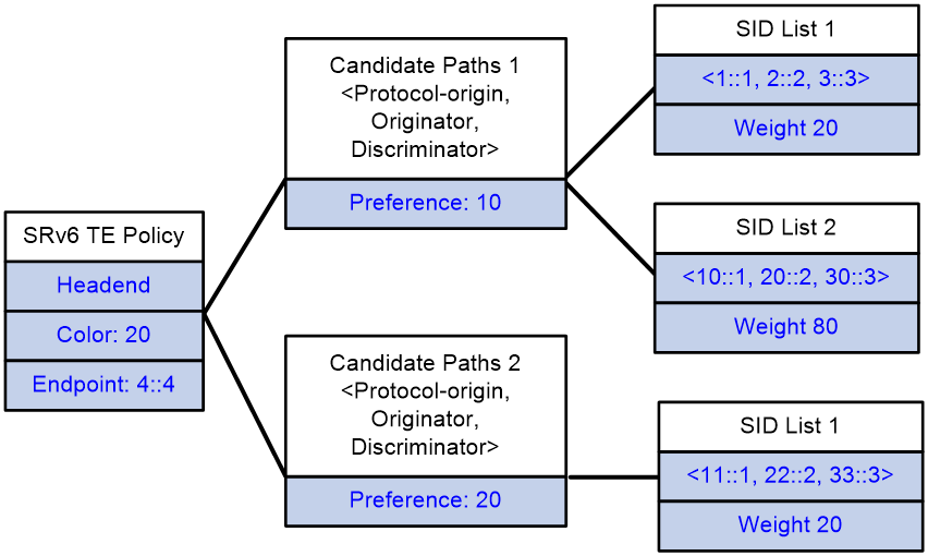
As show in Figure 1, an SRv6 TE policy consists of candidate paths with different preferences. Each candidate path can have one or multiple subpaths identified by segment lists (also called SID lists).
· Candidate path
An SRv6 TE policy can have multiple candidate paths. The device selects the candidate path with the greatest preference value as the primary path in that SRv6 TE policy. A candidate path is uniquely identified by the <Protocol-origin,Originator,Discriminator> triplet:
¡ Protocol-origin—Protocol or method through which the candidate path was generated.
¡ Originator—Node that generated the candidate path. This field always consists of two portions, AS number and node IP address.
¡ Discriminator—Candiate path ID, which is used to distinguish candidate paths with the same Protocol-origin and Originator values. For example, the controller deploys three candiate paths to the ingress node of an SRv6 TE policy through BGP. In this situation, the Protocol-origin and Originator values of those candiate paths are BGP and controller, respectively, but their Discriminator values are different.
Two SRv6 TE policies cannot share the same candidate path.
· SID list
A SID list is a list of SIDs that indicates a packet forwarding path. Each SID is the IPv6 address of a node on the forwarding path.
A candidate path can have a single SID list or multiple SID lists that use different weight values. After an SRv6 TE policy chooses a candidate path with multiple SID lists, the traffic will be load shared among the SID lists based on weight values.
· Binding SID
SRv6 TE policies also support Binding SIDs (BSID). A BSID is typically an SRv6 SID, which represents a candidate path. If the destination address of a packet is a BSID, the packet will be steered to the related candidate path for further forwarding. Assume that an SRv6 TE policy is a network service and you want to forward traffic along a specific candidate path of that SRv6 TE policy. From a programming perspective, you can use the BSID of that candidate path as an interface to call that network service.
You can manually configure a BSID for an SRv6 TE policy or leave the SRv6 TE policy to automatically obtain a BSID from the specified locator. The SRv6 endpoint behavior for BSID is Endpoint Bound to an SRv6 TE Policy (End.B6), because they are SRv6 SIDs indeed. End.B6 behaviors include the End.B6.Insert and End.B6.Encaps behaviors. For more information about End.B6 SRv6 SIDs, see SRv6 configuration in Segment Routing Configuration Guide.
Figure 1 SRv6 TE policy contents
SRv6 TE policy creation
SRv6 TE policy creation modes
An SRv6 TE policy can be created in the following modes:
· CLI- or NETCONF-based configuration
In this method, you need to manually configure the candidate settings for the SRv6 TE policy, such as candidate path preferences, SID lists and weights.
· Learning from a BGP IPv6 SR policy route
To support SRv6 TE policy, MP-BGP defines the BGP IPv6 SR policy address family and the SRv6 TE policy Network Layer Reachability Information (NLRI). The SRv6 TE policy NLRI is called the BGP IPv6 SR policy route. A BGP IPv6 SR policy route contains SRv6 TE policy settings, including the BSID, color, endpoint, candidate preferences, SID lists, and SID list weights.
The device can advertise its local SRv6 TE policy settings to its BGP IPv6 SR policy peer through a BGP IPv6 SR policy route. The peer device can create an SRv6 TE policy according to the received SRv6 TE policy settings.
· Automatic creation by ODN
When the device receives a BGP route, it compares the color extended attribute value of the BGP route with the color value of the ODN template. If the color values match, the device automatically generates an SRv6 TE policy and two candidate paths for the policy.
¡ The policy uses the BGP route's next hop address as the endpoint address and the ODN template's color value as the color attribute value of the policy.
¡ The candidate paths use preferences 100 and 200. You need to configure the SID lists for the candidate path with preference 200 through dynamic calculation based on affinity attribute or Flex-Algo, and use PCE to compute the SID lists for the candidate path with preference 100. For more information about SID list computation using PCE, see "SID list computation using PCE."
You can also manually create candidate paths for an ODN-created SRv6 TE policy.
SID list creation through dynamic path calculation
SID list creation through dynamic path calculation is supported on the source node of manually created SRv6 TE policies and automatically generated SRv6 TE policies through ODN.
The dynamic path calculation is performed based on affinity attribute or Flex-Algo.
Dynamic path calculation based on affinity attribute
An SRv6 TE policy performs dynamic path calculation based on affinity attribute as follows:
1. Select the links based on the affinity attribute rule.
The SRv6 TE policy selects links containing the bit values associated with the specified affinity attribute as required by the affinity attribute rule.
¡ Link attribute—A 32-bit binary number. Each bit represents an attribute with a value of 0 or 1.
¡ Affinity attribute bit position—The value range is 0 to 32. When the affinity attribute value is N, it is compared with the N+1 bit of the link attribute (from right to left). The affinity attribute applies to the link only if the N+1 bit value of the link attribute is 1.
For example, for affinity attribute name blue associated with bit 1 and affinity attribute name red associated with bit 5, the link selection varies by affinity attribute rule type:
¡ For the include-any affinity attribute rule, a link is available for use if the link attribute has the second bit (associated with affinity attribute blue) or sixth bit (associated with affinity attribute red) set to 1.
¡ For the include-all affinity attribute rule, a link is available for use if the link attribute has both the second bit (associated with affinity attribute blue) and sixth bit (associated with affinity attribute red) set to 1.
¡ For the exclude-any affinity attribute rule, a link is not available for use if the link attribute has the second bit (associated with affinity attribute blue) or sixth bit (associated with affinity attribute red) set to 1.
2. Select the links based on the specified metric.
The SRv6 TE policy supports the following metrics:
¡ Hop count—Selects the link with minimum hops.
¡ IGP link cost—Selects the link with minimum IGP link cost.
¡ Interface latency—Selects the link with the minimum interface latency.
¡ TE cost—Selects the link with minimum TE cost.
After path calculation, the device sorts all link- or node-associated SIDs on the path in an ascending order of distance, and creates an SID list for the SRv6 TE policy. During SID selection, End SIDs take precedence over End.X SIDs.
Dynamic path calculation based on Flex-Algo
The SRv6 TE policy uses the specified Flex-Algo to perform dynamic path calculation. After path calculation, the device sorts all link- or node-associated SIDs on the path in an ascending order of distance, and creates an SID list for the SRv6 TE policy. During SID selection, End SIDs take precedence over End.X SIDs.
For more information about path calculation based on Flex-Algo, see IS-IS configuration in Layer 3—IP Routing Configuration Guide.
SID list computation using PCE
On an SRv6 TE policy network, an SRv6 node can act as a Path Computation Client (PCC) to use the paths computed by the Path Computation Element (PCE) to create SID lists for a candidate path.
Basic concepts
· PCE—An entity that provides path computation for network devices. It can provide intra-area path computation as well as complete SID list computation on a complicated network. A PCE can be stateless or stateful.
¡ Stateless PCE—Provides only path computation.
¡ Stateful PCE—Knows all path information maintained by a PCC, and performs intra-area path recomputation and optimization. A stateful PCE can be active or passive.
- Active stateful PCE—Accepts path delegation requests sent by a PCC and optimizes the paths.
- Passive stateful PCE—Only maintains path information for SID lists of a PCC. A passive stateful PCE does not accept path delegation requests sent by a PCC or optimize the paths.
· PCC—A PCC sends a request to a PCE for path computation and uses the path information returned by the PCE to establish forwarding paths. For a PCC to establish a PCEP session with a PCE, the PCC and PCE must be of the same type.
¡ Stateless PCC—Sends path computation requests to a PCE.
¡ Stateful PCC—Delegates SID list information to a stateful PCE. A stateful PCE can be active or passive.
- Active stateful PCC—Reports its SID list information to a PCE, and uses the paths computed by the PCE to create and update the SID lists.
- Passive stateful PCC—Only reports its SID list information to a PCE but does not use the PCE to compute or update path information for the SID lists.
· PCEP—Path Computation Element Protocol. PCEP runs between a PCC and a PCE, or between PCEs. It is used to establish PCEP sessions to exchange PCEP messages over TCP connections.
PCE path computation
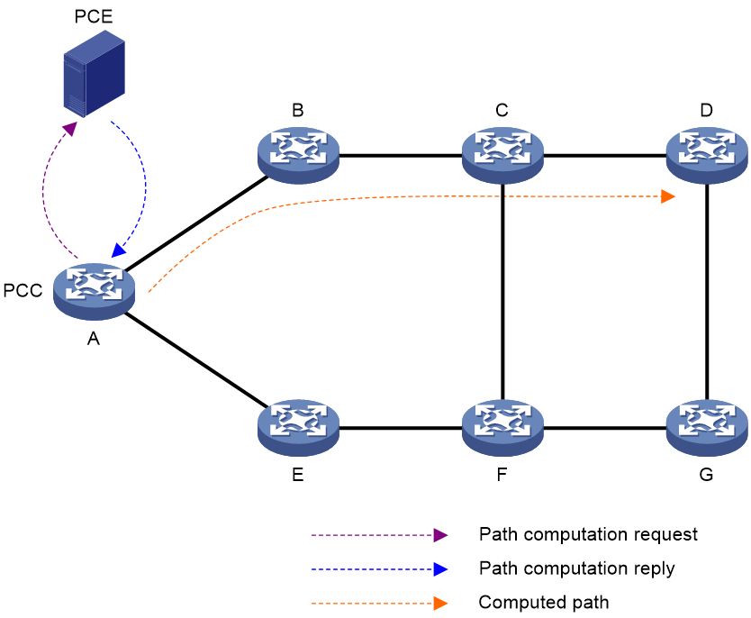
As shown in Figure 2, the PCE path computation procedure is as follows:
1. The PCC sends a path computation request to the PCE.
2. The PCE computes paths after it receives the request.
3. The PCE replies the PCC with the computed path information.
4. The PCC creates SID lists for the SRv6 TE policy candidate path according to the path information computed by the PCE.
Figure 2 Path computation using PCE
SRv6 TE policy validity
An SRv6 TE policy can be used for traffic forwarding only if it is valid. The device marks an SRv6 TE policy as valid only if that policy contains a minimum of one candidate path with valid SID lists. If all SID lists associated with candidate paths within an SRv6 TE policy are invalid, the device marks the SRv6 TE policy as invalid. An SID list is invalid in one of the following situations:
· The SID list is empty
· The weight of the SID list is 0.
· The SRv6 source node cannot communicate with the IPv6 address of the first hop in the SID list.
· Path connectivity verification is enabled on the ingress node of the SRv6 TE policy, and an SID in the SID list is found unreachable.
· BFD or SBFD is enabled for the SRv6 TE policy and the related BFD or SBFD session goes down. BFD session down events are enabled to trigger SRv6 TE policy path reselection.
SRv6 TE policy group
An SRv6 TE policy group is a group of SRv6 TE policies that have the same endpoint address. Upon receiving a packet destined for that endpoint address, the device searches for the SRv6 TE policy containing the color value mapped to the DSCP or 802.1p value of the packet. The device will use the SRv6 TE policy to forward the packet.
On the same SRv6 source node, you can create an SRv6 TE policy group and multiple SRv6 TE policies. Those SRv6 TE policies can be added into that SRv6 TE policy group only if the following conditions exist:
· The SRv6 TE policies have the same destination node.
· Traffic identifier-to-SRv6 TE policy mappings are configured for the SRv6 TE policy group.
An SRv6 TE policy group can participate in traffic forwarding only if it contains valid SRv6 TE policies.
An SRv6 TE policy group is identified by its group ID. It also has the following attributes:
· Color—Color attribute of the SRv6 TE policy group. BGP routes that carry the same color value as the SRv6 TE policy group are recursed to the SRv6 TE policy group.
· Endpoint—IPv6 address of the egress node (destination node). If an SRv6 TE policy and an SRv6 TE policy group have the same value for the endpoint attribute, the SRv6 TE policy belongs to the SRv6 TE policy group.
You can create an SRv6 TE policy group by using the following methods:
· Manual creation at the CLI
This method requires manually configuring the destination node address of the SRv6 TE policy group.
· Automatic creation by ODN
When the device receives a BGP route, it compares the color extended attribute value of the BGP route with the color value of the ODN template. If the color values match, the device automatically generates an SRv6 TE policy group.
¡ The policy group uses the BGP route's next hop address as the endpoint address and the ODN template's color value as the color attribute value.
¡ The device will assign the smallest ID that is not in use to the SRv6 TE policy group.
Traffic steering to an SRv6 TE policy
About this feature
During traffic steering to SRv6 TE policies, the device performs the following operations in sequence:
1. Finds recursive SRv6 TE policy tunnels for the route that directs traffic from the ingress node to the egress node.
2. Selects an SRv6 TE policy for traffic forwarding from the the ingress node to the egress node.
Therefore, traffic steering to SRv6 TE policies involves two phases, route recursion and path selection. This section focuses on the path selection process. For more information about route recursion to SRv6 TE policies, see SRv6 VPN configuration in Segment Routing Configuration Guide.
Path selection in SRv6 TE policy-oriented traffic steering can be divided into two modes: direct steering and indirect steering. The methods for direct traffic steering include:
· Color-based traffic steering
· Automatic route advertisement
· Other traffic steering methods
During indirect traffic steering, the device performs the following operations in sequence:
1. Steers traffic to the matching SRv6 TE policy group.
2. Based on the forward type and forwarding policy mappings of that SRv6 TE policy group, selects an SRv6 TE policy group for further forwarding.
The methods for indirect traffic steering include:
· 802.1p-based traffic steering
· Service class-based traffic steering
· TE class ID-based traffic steering
· APN ID-based traffic steering
· ARN ID-based traffic steering
BSID-based traffic steering
If the destination IPv6 address of a received packet is the BSID of an SRv6 TE policy, the device uses the SRv6 TE policy to forward the packet.
This traffic steering method is used in SID stitching scenarios. The BSID of an SRv6 TE policy is inserted into the segment list of another SRv6 TE policy, and the inserted BSID represents the segment lists of the optimal candidate path in the SRv6 TE policy. With this method, the SRH is shortened and different SRv6 TE policies can stitched together.
Color-based traffic steering
Traffic steering mechanism
In color-based traffic steering, the device searches for an SRv6 TE policy that has the same color and endpoint address as the color and next hop address of a BGP route. If a matching SRv6 TE policy exists, the device recurses the BGP route to that SRv6 TE policy. When the device receives packets that match the BGP route, it forwards those packets through the SRv6 TE policy.
Traffic steering workflow
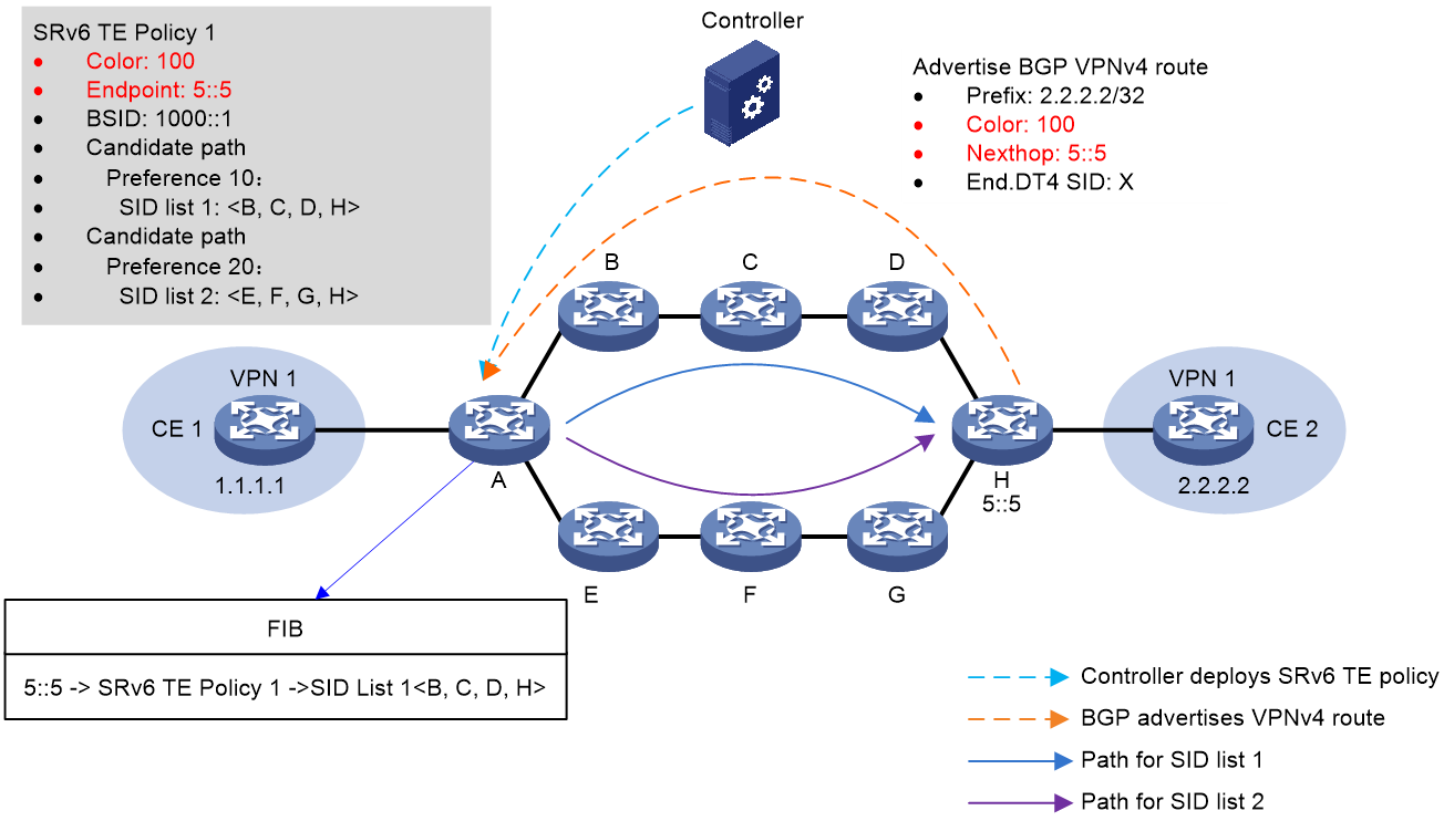
Figure 3 shows the process of color-based traffic steering:
1. The controller issues SRv6 TE policy 1 to Device A (source node). The color value and endpoint address of the SRv6 TE policy is 100 and 5::5 (IP address of Device H), respectively.
2. Device H advertises BGP VPNv4 route 2.2.2.2/32 to Device A. The color value and next hop address of the route is 100 and 5::5, respectively.
3. When Device A receives BGP VPNv4 route 2.2.2.2/32, it recurses this route to SRv6 TE policy 1 based on the route's color value and next hop address. Packets matching the BGP route will be forwarded through SRv6 TE policy 1.
Figure 3 Color-based traffic steering
DSCP-based traffic steering
Traffic steering mechanism
DSCP-based traffic steering is available only after SRv6 TE policy groups are deployed on the device. Each SRv6 TE policy group consists of multiple SRv6 TE policies with different colors but the same endpoint address.
To achieve DSCP-based traffic steering, you can perform the following operations:
1. Add multiple SRv6 TE policies with different colors to the same SRv6 TE policy group, and configure color-to-DSCP mappings for that SRv6 TE policy group.
2. Use one of the following methods to steer traffic to the SRv6 TE policy group:
¡ Bind the desired destination address to the SRv6 TE policy group in a tunnel policy. Traffic destined for the destination address will be steered to the SRv6 TE policy group for further forwarding.
¡ Set SRv6 TE policy group as the preferred tunnel type in a tunnel policy. When the next hop address of a route is the endpoint address of the SRv6 TE policy group, the device preferentially steers traffic to the SRv6 TE policy group.
¡ Recurse BGP routes that can match the SRv6 TE policy group to the SRv6 TE policy group. A BGP route can match an SRv6 TE policy group only if its color value and next hop address can match the color value and endpoint address of that SRv6 TE policy group.
3. Look up for the color value mapped to the DSCP value of a packet, and then use the color value to find the associated SRv6 TE policy in the SRv6 TE policy group.
The above task creates a DSCP > color > SRv6 TE policy mapping, enabling DSCP-based traffic steering to the desired SRv6 TE policy.
Traffic steering workflow
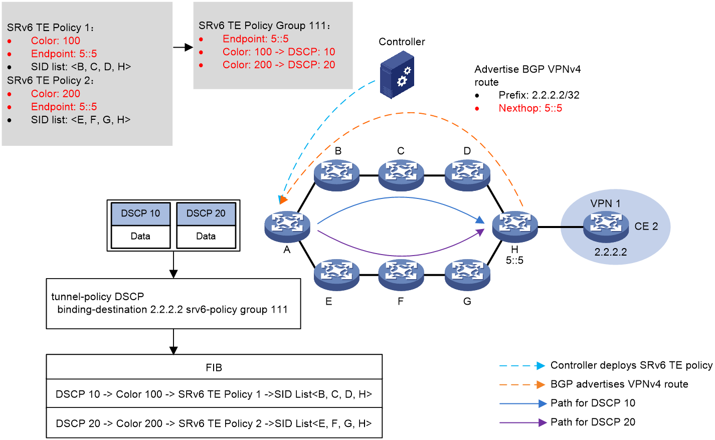
Figure 4 shows the process of DSCP-based traffic steering:
1. The controller issues SRv6 TE policy 1 and SRv6 TE policy 2 to Device A (source node). SRv6 TE policy 1 to Device A (source node). The color values of SRv6 TE policy 1 and SRv6 TE policy 2 are 100 and 200, respectively. The two SRv6 TE policies both use 5::5 as endpoint address, which is the IP address of Device H.
2. Device H advertises BGP VPNv4 route 2.2.2.2/32 to Device A. The next hop address of the route is 5::5.
3. SRv6 TE policy group 111 is created on Device A with its endpoint address as 5::5. Within the SRv6 TE policy group, color value 100 is mapped to DSCP value 10, and color value 200 is mapped to DSCP value 20. A tunnel policy is configured on Device A to bind the SRv6 TE policy group to destination address 2.2.2.2.
4. Device A performs DSCP-based traffic steering for a received packet as follows:
a. Finds the matching tunnel binding policy based on the packet's destination address, and then finds the related SRv6 TE policy group.
b. Uses the packet's DSCP value (10 in this example) to find the mapped color value, and then matches an SRv6 TE policy inside the SRv6 TE policy group based on the color value.
c. Uses the optimal candidate path in this SRv6 TE policy for packet forwarding. In this example, the packet is forwarded along the Device B > Device C > Device D > Device H path, which is in accordance with the SID list in the candidate path.
Figure 4 DSCP-based traffic steering
802.1p-based traffic steering
Traffic steering mechanism
802.1p-based traffic steering is available only after SRv6 TE policy groups are deployed on the device. Each SRv6 TE policy group consists of multiple SRv6 TE policies with different colors but the same endpoint address.
To achieve 802.1p-based traffic steering, you can perform the following operations:
1. Add multiple SRv6 TE policies with different colors to the same SRv6 TE policy group, and configure color-to-802.1p mappings for that SRv6 TE policy group.
2. Use one of the following methods to steer traffic to the SRv6 TE policy group:
¡ Bind the desired destination address to the SRv6 TE policy group in a tunnel policy. Traffic destined for the destination address will be steered to the SRv6 TE policy group for further forwarding.
¡ Set SRv6 TE policy group as the preferred tunnel type in a tunnel policy. When the next hop address of a route is the endpoint address of the SRv6 TE policy group, the device preferentially steers traffic to the SRv6 TE policy group.
¡ Recurse BGP routes that can match the SRv6 TE policy group to the SRv6 TE policy group. A BGP route can match an SRv6 TE policy group only if its color value and next hop address can match the color value and endpoint address of that SRv6 TE policy group.
3. Look up for the color value mapped to the 802.1p value of a packet, and then use the color value to find the associated SRv6 TE policy in the SRv6 TE policy group.
The above task creates a 802.1p > color > SRv6 TE policy mapping, enabling 802.1p-based traffic steering to the desired SRv6 TE policy.
Traffic steering workflow
Figure 5 shows the process of 802.1p-based traffic steering:
1. The controller issues SRv6 TE policy 1 and SRv6 TE policy 2 to Device A (source node). SRv6 TE policy 1 to Device A (source node). The color values of SRv6 TE policy 1 and SRv6 TE policy 2 are 100 and 200, respectively. The two SRv6 TE policies both use 5::5 as endpoint address, which is the IP address of Device H.
2. Device H advertises BGP VPNv4 route 2.2.2.2/32 to Device A. The next hop address of the route is 5::5.
3. SRv6 TE policy group 111 is created on Device A with its endpoint address as 5::5. Within the SRv6 TE policy group, color value 100 is mapped to 802.1p value 10, and color value 200 is mapped to 802.1p value 20. A tunnel policy is configured on Device A to bind the SRv6 TE policy group to destination address 2.2.2.2.
4. Device A performs 802.1p-based traffic steering for a received packet as follows:
a. Finds the matching tunnel binding policy based on the packet's destination address, and then finds the related SRv6 TE policy group.
b. Uses the packet's 802.1p value (10 in this example) to find the mapped color value, and then matches an SRv6 TE policy inside the SRv6 TE policy group based on the color value.
c. Uses the optimal candidate path in this SRv6 TE policy for packet forwarding. In this example, the packet is forwarded along the Device B > Device C > Device D > Device H path, which is in accordance with the SID list in the candidate path.
Figure 5 802.1p-based traffic steering

Service class-based traffic steering
Traffic steering mechanism
A service class is a local traffic identifier for devices, which can identify the service class of traffic by QoS policy. You can use the remark service-class command to assign a service class to traffic. For more information about this command, see QoS commands in ACL and QoS Command Reference. Service class-based traffic steering is available only after SRv6 TE policy groups are deployed on the device. Each SRv6 TE policy group consists of multiple SRv6 TE policies with different colors but the same endpoint address.
To achieve service class-based traffic steering, you can perform the following operations:
1. Add multiple SRv6 TE policies with different colors to the same SRv6 TE policy group, and configure color-to-service class mappings for that SRv6 TE policy group.
2. Use one of the following methods to steer traffic to the SRv6 TE policy group:
¡ Bind the desired destination address to the SRv6 TE policy group in a tunnel policy. Traffic destined for the destination address will be steered to the SRv6 TE policy group for further forwarding.
¡ Set SRv6 TE policy group as the preferred tunnel type in a tunnel policy. When the next hop address of a route is the endpoint address of the SRv6 TE policy group, the device preferentially steers traffic to the SRv6 TE policy group.
¡ Recurse BGP routes that can match the SRv6 TE policy group to the SRv6 TE policy group. A BGP route can match an SRv6 TE policy group only if its color value and next hop address can match the color value and endpoint address of that SRv6 TE policy group.
3. Look up for the color value mapped to the service class of a packet, and then use the color value to find the associated SRv6 TE policy in the SRv6 TE policy group.
The above task creates a service class > color > SRv6 TE policy mapping, enabling service class-based traffic steering to the desired SRv6 TE policy.
Traffic steering workflow
Figure 6 shows the process of service class-based traffic steering:
1. The controller issues SRv6 TE policy 1 and SRv6 TE policy 2 to Device A (source node). SRv6 TE policy 1 to Device A (source node). The color values of SRv6 TE policy 1 and SRv6 TE policy 2 are 100 and 200, respectively. The two SRv6 TE policies both use 5::5 as endpoint address, which is the IP address of Device H.
2. Device H advertises BGP VPNv4 route 2.2.2.2/32 to Device A. The next hop address of the route is 5::5.
3. SRv6 TE policy group 111 is created on Device A with its endpoint address as 5::5. Within the SRv6 TE policy group, color value 100 is mapped to service class 1, and color value 200 is mapped to service class 2. A tunnel policy is configured on Device A to bind the SRv6 TE policy group to destination address 2.2.2.2.
4. Device A performs service class-based traffic steering for a received packet as follows:
a. Finds the matching tunnel binding policy based on the packet's destination address, and then finds the related SRv6 TE policy group.
b. Uses the packet's service class (1 in this example) to find the mapped color value, and then matches an SRv6 TE policy inside the SRv6 TE policy group based on the color value.
c. Uses the optimal candidate path in this SRv6 TE policy for packet forwarding. In this example, the packet is forwarded along the Device B > Device C > Device D > Device H path, which is in accordance with the SID list in the candidate path.
Figure 6 Service class-based traffic steering

CBTS-based traffic steering
About SRv6 TE policy CBTS
SRv6 TE policy Class Based Tunnel Selection (CBTS) enables dynamic routing and forwarding of traffic with service class values over different SRv6 TE policy tunnels between the same tunnel headend and tailend. CBTS uses a dedicated tunnel for a certain class of service to implement differentiated forwarding for services.
How SRv6 TE policy CBTS works
SRv6 TE policy CBTS processes traffic mapped to a priority as follows:
1. Uses a traffic behavior to set a service class value for the traffic. For more information about setting a service class value in traffic behavior view, see the remark service-class command in ACL and QoS Command Reference.
2. Compares the service class value of the traffic with the service class values of the SRv6 TE policy tunnels and forwards the traffic to a matching tunnel.
SRv6 TE policy selection rules
SRv6 TE policy CBTS uses the following rules to select an SRv6 TE policy for the traffic to be forwarded:
· If an SRv6 TE policy has the same service class value as the traffic, CBTS uses this SRv6 TE policy.
· If multiple SRv6 TE policies have the same service class value as the traffic, CBTS selects an SRv6 TE policy based on the flow identification and load sharing mode:
¡ If only one flow exists and flow-based load sharing is used, CBTS randomly selects a matching SRv6 TE policy for packets of the flow.
¡ If multiple flows exist or if only one flow exists but packet-based load sharing is used, CBTS uses all matching SRv6 TE policies to load share the packets.
For more information about the flow identification and load sharing mode, see the ip load-sharing mode command in Layer 3—IP Services Command Reference.
· If the traffic does not match any SRv6 TE policy by service class value, CBTS randomly selects an SRv6 TE policy from all SRv6 TE policies with the lowest forwarding priority. An SRv6 TE policy that has a smaller service class value has a lower forwarding priority. An SRv6 TE policy that is not configured with a service class value has the lowest priority.
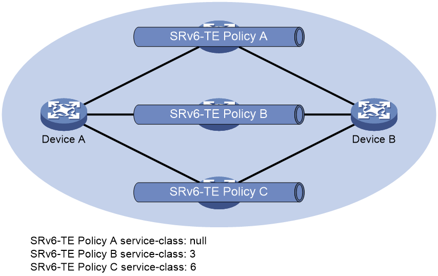
SRv6 TE policy CBTS application scenario
As shown in Figure 7, CBTS selects SRv6 TE policies for traffic from Device A to Device B as follows:
· Uses SRv6 TE policy B to forward traffic with service class value 3.
· Uses SRv6 TE policy C to forward traffic with service class value 6.
· Uses SRv6 TE policy A to forward traffic with service class value 4.
· Uses SRv6 TE policy A to forward traffic with no service class value.
Figure 7 Uses SRv6 TE policy CBTS application scenario
TE class ID-based traffic steering
Traffic steering mechanism
A TE class ID is a local traffic identifier for devices, which can identify the TE class ID of traffic by QoS policy. TE class ID-based traffic steering is more suitable than service class-based traffic steering, because this method can provide support for Intelligent Policy Route (IPR) and TE class IDs outnumber service classes. You can use the remark te-class command to assign a TE class ID to traffic. For more information about this command, see QoS commands in ACL and QoS Command Reference. TE class ID-based traffic steering is available only after SRv6 TE policy groups are deployed on the device. Each SRv6 TE policy group consists of multiple SRv6 TE policies with different colors but the same endpoint address.
To achieve TE class ID-based traffic steering, you can perform the following operations:
1. Add multiple SRv6 TE policies with different colors to the same SRv6 TE policy group, and configure color-to-TE class ID mappings for that SRv6 TE policy group.
2. Use one of the following methods to steer traffic to the SRv6 TE policy group:
¡ Bind the desired destination address to the SRv6 TE policy group in a tunnel policy. Traffic destined for the destination address will be steered to the SRv6 TE policy group for further forwarding.
¡ Set SRv6 TE policy group as the preferred tunnel type in a tunnel policy. When the next hop address of a route is the endpoint address of the SRv6 TE policy group, the device preferentially steers traffic to the SRv6 TE policy group.
¡ Recurse BGP routes that can match the SRv6 TE policy group to the SRv6 TE policy group. A BGP route can match an SRv6 TE policy group only if its color value and next hop address can match the color value and endpoint address of that SRv6 TE policy group.
3. Look up for the color value mapped to the TE class ID of a packet, and then use the color value to find the associated SRv6 TE policy in the SRv6 TE policy group.
The above task creates a TE class ID > color > SRv6 TE policy mapping, enabling TE class ID-based traffic steering to the desired SRv6 TE policy.
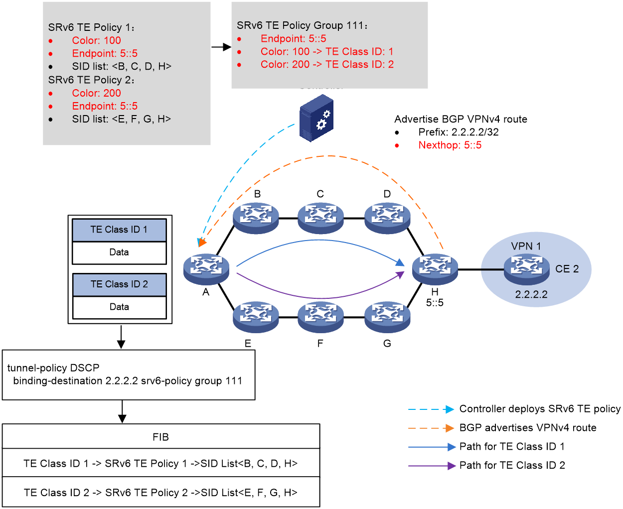
Traffic steering workflow
Figure 6 shows the process of TE class ID-based traffic steering:
1. The controller issues SRv6 TE policy 1 and SRv6 TE policy 2 to Device A (source node). SRv6 TE policy 1 to Device A (source node). The color values of SRv6 TE policy 1 and SRv6 TE policy 2 are 100 and 200, respectively. The two SRv6 TE policies both use 5::5 as endpoint address, which is the IP address of Device H.
2. Device H advertises BGP VPNv4 route 2.2.2.2/32 to Device A. The next hop address of the route is 5::5.
3. SRv6 TE policy group 111 is created on Device A with its endpoint address as 5::5. Within the SRv6 TE policy group, color value 100 is mapped to TE class ID 1, and color value 200 is mapped to TE class ID 2. A tunnel policy is configured on Device A to bind the SRv6 TE policy group to destination address 2.2.2.2.
4. Device A performs TE class ID-based traffic steering for a received packet as follows:
a. Finds the matching tunnel binding policy based on the packet's destination address, and then finds the related SRv6 TE policy group.
b. Uses the packet's TE class ID (1 in this example) to find the mapped color value, and then matches an SRv6 TE policy inside the SRv6 TE policy group based on the color value.
c. Uses the optimal candidate path in this SRv6 TE policy for packet forwarding. In this example, the packet is forwarded along the Device B > Device C > Device D > Device H path, which is in accordance with the SID list in the candidate path.
Figure 8 TE class ID-based traffic steering
APN ID-based traffic steering
Once service traffic is steered to an SRv6 TE policy group for forwarding, the device matches the APN ID of the traffic with the color-to-APN ID mappings in the SRv6 TE policy group. If a match is found, the device forwards the traffic through the SRv6 TE policy associated with the color value in the matching mapping.
For more information about APN ID-based traffic steering, see "SRv6 TE policy application in the APN6 network."
ARN ID-based traffic steering
Once service traffic is steered to an SRv6 TE policy group for forwarding, the device matches the ARN ID of the traffic with the color-to-ARN ID mappings in the SRv6 TE policy group. If a match is found, the device forwards the traffic through the SRv6 TE policy associated with the color value in the matching mapping.
For more information about ARN ID-based traffic steering, see "SRv6 TE policy application in the ARN network."
Automatic route advertisement
This feature advertises an SRv6 TE policy or an SRv6 TE policy group (a group of SRv6 TE policies) to IGP (IPv6 IS-IS or OSPFv3) for route computation. The device can then forward the matching traffic through the SRv6 TE policy or SRv6 TE policy group.
An SRv6 TE policy or SRv6 TE policy group supports only automatic route advertisement (also called autoroute announce) in IGP shortcut mode. With automatic route advertisement enabled, the device determines the SRv6 TE policy or SRv6 TE policy group as a link that connects the tunnel ingress and egress. The tunnel ingress includes the SRv6 TE policy or SRv6 TE policy group in IGP route computation.
|
|
NOTE: After traffic is steered to an SRv6 TE policy group through automatic route advertisement, the device looks up for the matching SRv6 TE policy in the SRv6 TE policy group based on DSCP or 802.1p value. Then, the device forwards the traffic through the matching SRv6 TE policy. |
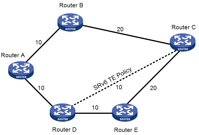
As shown in Figure 9, an SRv6 TE policy tunnel is deployed between Device D and Device C. IGP Shortcut enables the source node, Device D, to utilize this tunnel during IGP route computation. Consequently, Device D can steer incoming packets to the SRv6 TE policy tunnel between Device D and Device C.
Figure 9 Automatic route advertisement
Other traffic steering methods
· Tunnel policy-based traffic steering—By deploying a tunnel policy in an IP L3VPN, EVPN L3VPN, EVPN VPLS, or EVPN VPWS network, you can use an SRv6 TE policy as the public tunnel to forward VPN traffic. For more information about tunnel policies, see tunnel policy configuration in MPLS Configuration Guide.
· Static routing-based traffic steering—This traffic steering method requires recursing a static route to an SRv6 TE policy. The device can then use the SRv6 TE policy to forward packets that match the static route.
· PBR-based traffic steering—This traffic steering method directs traffic to an SRv6 TE policy through PBR. The device uses the SRv6 TE policy to forward packets that match the PBR policy. For more information about PBR, see PBR configuration in Layer 3—IP Routing Configuration Guide.
· QoS policy-based traffic steering—This traffic steering method redirects traffic to an SRv6 TE policy through a QoS policy. The device can then use the SRv6 TE policy to forward packets that match the traffic classes of the QoS policy. For more information about QoS policies, see QoS configuration in ACL and QoS Configuration Guide.
· Flowspec-based traffic steering—This traffic steering method redirects traffic to an SRv6 TE policy through a Flowspec rule. The device can then use the SRv6 TE policy to forward packets that match the Flowspec rule. For more information about Flowspec, see Flowspec configuration in ACL and QoS Configuration Guide.
SRv6 TE policy-based traffic forwarding
SRv6 TE policy path selection
After traffic is steered in to an SRv6 TE policy, the device selects a traffic forwarding path in that SRv6 TE policy as follows:
1. Selects the valid candidate path that has the highest preference.
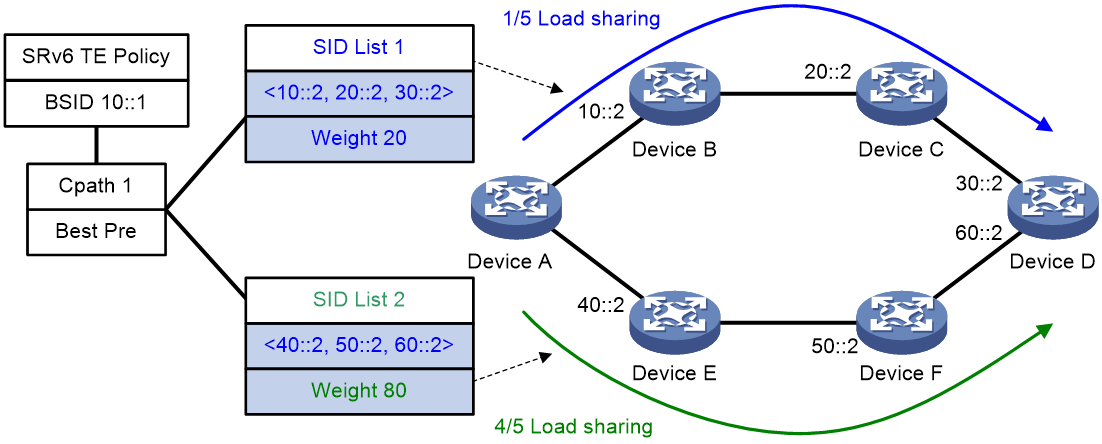
2. Performs Weighted ECMP (WECMP) load sharing among the SID lists of the selected candidate path. The ratio of load on SID list x is equal to Weight x/(Weight 1 + Weight 2 + … + Weight n). The n argument represents the number of SID lists in the selected candidate path.
As shown in Figure 10, Device A first selects a valid SRv6 TE policy by BSID. Then, the device selects a candidate path by preference. The candidate path has two valid SID lists: SID list 1 and SID list 2. The weight value of SID list 1 is 20 and the weight value of SID list 2 is 80. One fifth of the traffic will be forwarded through the subpath identified by SID list 1. Four fifth of the traffic will be forwarded through the subpath identified by SID list 2.
Figure 10 SRv6 TE policy path selection
Data encapsulation and forwarding through SRv6 TE policies
For SRv6 TE policies, supported packet encapsulation methods include normal encapsulation and insert encapsulation. In normal encapsulation, the device adds a new IPv6 header and an SRH to each packet. In insert encapsulation, the device inserts an SRH extension header after the original IPv6 header.
The packet forwarding process varies by packet encapsulation method.
SRv6 TE policy-based packet forwarding with the normal encapsulation method
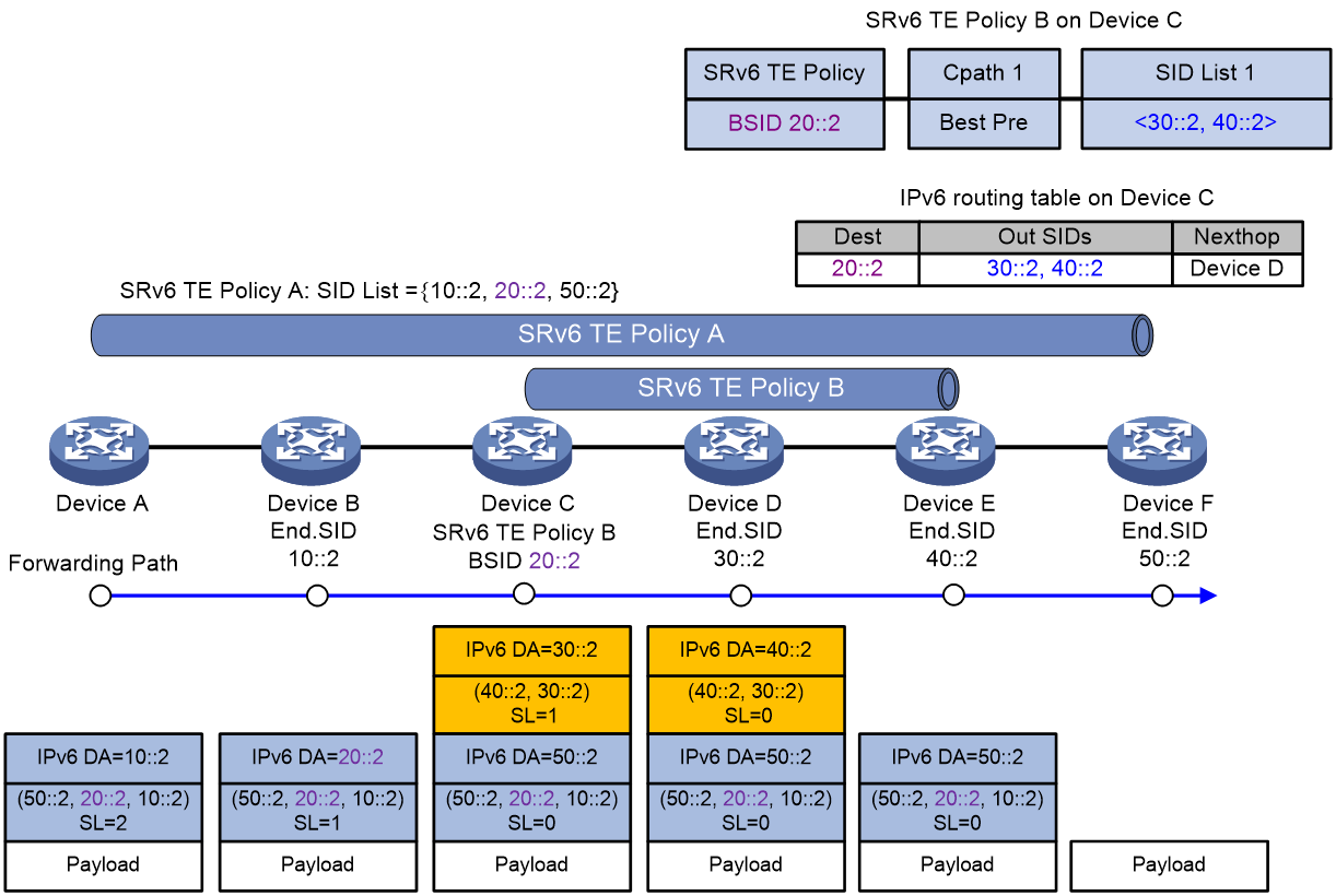
As shown in Figure 11, BSID-based traffic steering is used in the SID stitching scenario. The packet forwarding process is as follows:
1. Device A steers traffic to SRv6 TE policy A for further forwarding. The SIDs of SRv6 TE policy A are stitched with the BSID of SRv6 TE policy B, 20::2. According to SRv6 TE policy A, the device encapsulates the packet with an SRH header that carries an SID list of {10::2, 20::2, 50::2}. 10::2 represents the End SID of Device B, and 50::2 represents the End SID of Device F.
2. Device A transmits the encapsulated packet to the next hop, Device B.
3. Device B obtains next hop information (Device C) from the SRH of the encapsulated packet, and transmits the packet to Device C.
4. Device C finds that the encapsulated packet is heading for 20::2, which is the BSID of SRv6 TE policy B. The encapsulation method for SRv6 TE policy B is normal encapsulation. Therefore, Device C encapsulates the packet with an outer IPv6 header and an SRH according to SRv6 TE policy B. The SRH carries a SID list of {30::2, 40::2}, where 30::2 is the End SID for Device D, and 40::2 is the End SID for Device E. The destination address in the outer IPv6 header is updated to 30::2, with the next hop set to Device D. After packet encapsulation, Device C transmits the packet to Device D.
5. Device D finds that the next hop pointed by the outer SRH of the encapsulated packet is Device E, and then transmits the packet to Device E.
6. Device E finds that the SL value in the outer SRH of the encapsulated packet is 0, and thus perform the following operations:
a. Decapsulates the packet by removing its outer IPv6 header and SRH.
b. Transmits the packet to Device F, which is the destination address of the packet.
7. Device F finds that the SL value in the outer SRH of the encapsulated packet is 0. As the egress node of SRv6 TE policy A, Device F decapsulates the packet by removing its outer IPv6 header and SRH.
Figure 11 SRv6 TE policy-based packet forwarding with the normal encapsulation method
SRv6 TE policy-based packet forwarding with the insert encapsulation method
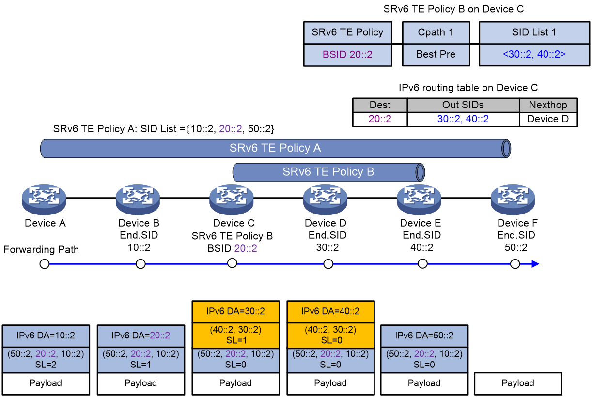
As shown in Figure 12, BSID-based traffic steering is used in the SID stitching scenario. The packet forwarding process is as follows:
1. Device A steers traffic to SRv6 TE policy A for further forwarding. The SIDs of SRv6 TE policy A are stitched with the BSID of SRv6 TE policy B, 20::2. According to SRv6 TE policy A, the device encapsulates the packet with an SRH that carries an SID list of {10::2, 20::2, 50::2}. 10::2 represents the End SID of Device B, and 50::2 represents the End SID of Device F.
2. Device A transmits the encapsulated packet to the next hop, Device B.
3. Device B obtains next hop information (Device C) from the SRH of the encapsulated packet, and transmits the packet to Device C.
4. Device C finds that the encapsulated packet is heading for 20::2, which is the BSID of SRv6 TE policy B. The encapsulation method for SRv6 TE policy B is insert encapsulation. Therefore, Device C inserts an SRH after the original IPv6 header of the packet according to SRv6 TE policy B. The SRH carries a SID list of {30::2, 40::2}, where 30::2 is the End SID for Device D, and 40::2 is the End SID for Device E. The destination address in the outer IPv6 header is updated to 30::2, with the next hop set to Device D. After packet encapsulation, Device C transmits the packet to Device D.
5. Device D finds that the next hop pointed by the outer SRH of the encapsulated packet is Device E, and then transmits the packet to Device E.
6. Device E finds that the SL value in the outer SRH of the encapsulated packet is 0, and thus perform the following operations for the packet:
a. Removes the outer SRH and updates the destination address in the outer IPv6 header to 50::2.
b. Transmits the packet to Device F, which is the destination address of the packet.
7. Device F finds that the SL value in the outer SRH of the encapsulated packet is 0. As the egress node of SRv6 TE policy A, Device F decapsulates the packet by removing its outer IPv6 header and SRH.
Figure 12 SRv6 TE policy-based packet forwarding with the insert encapsulation method
SRv6 TE policy reliability
SRv6 TE policy hot standby
If an SRv6 TE policy has multiple valid candidate paths, the device chooses the candidate path with the greatest preference value. If the chosen path fails, the SRv6 TE policy must select another candidate path. During path reselection, packet loss might occur and thus affect service continuity.
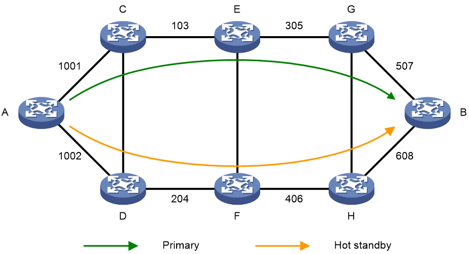
The SRv6 TE hot standby feature can address this issue. This feature takes the candidate path with the greatest preference value as the primary path and that with the second greatest preference value as the backup path in hot standby state. As shown in Figure 13, when the forwarding paths corresponding to all SID lists of the primary path fails, the standby path immediately takes over to minimize service interruption.
Figure 13 SRv6 TE policy hot standby
You can configure both the hot standby and SBFD features for an SRv6 TE policy. Use SBFD to detect the availability of the primary and standby paths specified for hot standby. If all SID lists of the primary path become unavailable, the standby path takes over and a path recalculation is performed. The standby path becomes the new primary path, and a new standby path is selected. If both the primary and standby paths fail, the SRv6 TE policy will calculate new primary and standby paths.
BFD for SRv6 TE policy
Echo BFD for SRv6 TE policy
Echo BFD (BFD in echo packet mode) does not require the initiator and the reflector use the same discriminator for testing the connectivity of an SRv6 TE policy. As such, you do not need to plan local and remote discriminators. This makes echo BFD easier to configure than SBFD for SRv6 TE policy.
Echo BFD tests the connectivity of an SRv6 TE policy as follows:
1. The source node sends BFD echo packets that each encapsulate a SID list of the SRv6 TE policy.
2. After the endpoint node receives an BFD echo packet, it sends the BFD echo packet back to the source node along the shortest path selected through IPv6 routing table lookup.
3. If the source node receives the BFD echo packet within the detection timeout time, it determines that the SID list (forwarding path) under test is available. If no BFD echo packet is received, the device determines that the SID list is faulty. If all the SID lists for the primary path are faulty, BFD triggers a primary-to-backup path switchover.
If multiple SID lists are present in the selected candidate path, the SRv6 TE policy establishes separate BFD sessions to monitor the forwarding path corresponding to each SID list.
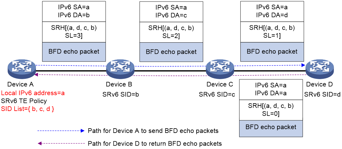
When echo BFD is enabled for an SRv6 TE policy, BFD packets can be encapsulated in Insert or Encaps mode. By default, BFD packets use the Insert encapsulation mode.
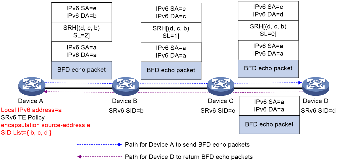
As shown in Figure 14, configure an SRv6 TE policy on Device A and use echo BFD to detect the policy connectivity. If Insert encapsulation is used for BFD packets, Device A constructs a special BFD packet with its local IPv6 address (a) as the source address and inserts IPv6 address a to the SL=0 position in the SID list. When Device D receives the BFD packet, it updates the destination address in the IPv6 header to a, and uses IPv6 address a to look up the routing table to send the packet back to Device A.
|
|
NOTE: For more information about selecting the source address for BFD packets, see “Enabling echo BFD for SRv6 TE policies.” |
Figure 14 Echo BFD for SRv6 TE policy with Insert encapsulation
As shown in Figure 15, Device A configures an SRv6 TE policy and uses echo BFD to detect connectivity for this policy. If Encaps encapsulation is used for BFD packets, Device A first constructs a BFD packet with both source and destination addresses set to its local IPv6 address a. Then, Device A encapsulates the BFD packet with an additional IPv6 header and an SRH header. The outer IPv6 header's source address is specified by the encapsulation source-address command, and the SRH header contains the SID list of the SRv6 TE policy. When Device D receives the BFD packet, it performs decapsulation on the outer IPv6 and SRH headers, and then uses IPv6 address a to look up the IPv6 routing table to send the packet back to Device A.
|
|
NOTE: For more information about selecting the source address for BFD packets, see "Enabling echo BFD for SRv6 TE policies." |
Figure 15 Echo BFD for SRv6 TE policy with Encaps encapsulation
SBFD for SRv6 TE policy
SRv6 use seamless BFD (SBFD) to detect path connectivity of SRv6 TE policies, instead of sending messages between nodes. SBFD enables an SRv6 TE policy to detect path failures in milliseconds for fast path switchover.
SBFD detects the connectivity of an SRv6 TE policy as follows:
1. The source node (the initiator) sends SBFD packets that encapsulate the SID lists of the primary and backup candidate paths of the SRv6 TE policy.
2. After the endpoint node (the reflector) receives an SBFD packet, it checks whether the remote discriminator carried the packet is the same as the local discriminator. If yes, the reflector sends the SBFD response packet to the initiator by using the IPv6 routing table. If not, the reflector drops the SBFD packet.
3. If the source node can receive the SBFD response within the detection timeout time, it determines the corresponding SID list (forwarding path) of the SRv6 TE policy is available. If no response is received, the source node determines that the SID list is faulty.
If multiple SID lists are present in the selected candidate path, the SRv6 TE policy establishes separate SBFD sessions to monitor the forwarding path corresponding to each SID list.
When SBFD is enabled for an SRv6 TE policy, SBFD packets can be encapsulated in Insert or Encaps mode. By default, SBFD packets use the Insert encapsulation mode.
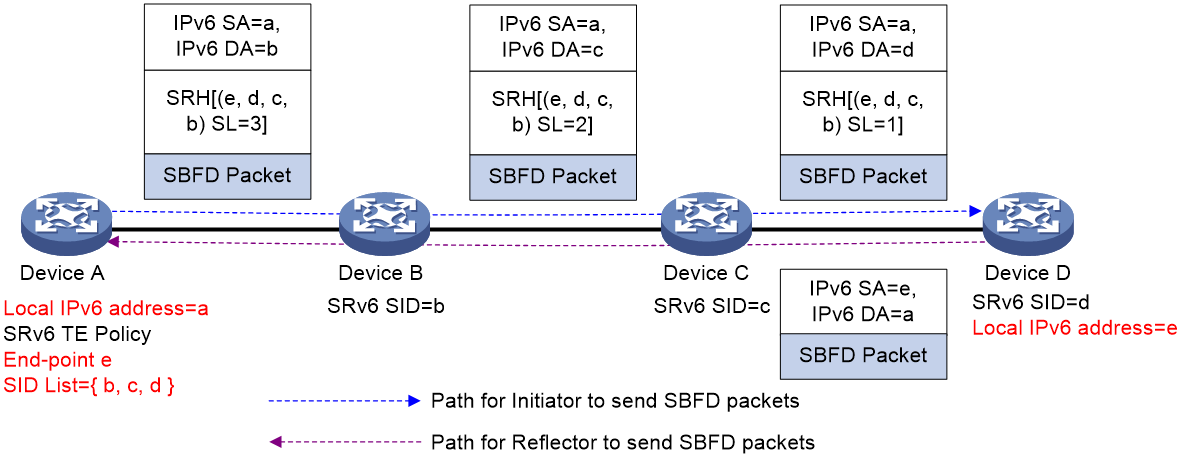
As shown in Figure 16, Device A configures an SRv6 TE policy and uses SBFD to detect connectivity for this policy. When using Insert encapsulation for SBFD packets, Device A constructs an SBFD packet with its local IPv6 address a as the source address and inserts the endpoint address e of the SRv6 TE policy to the SL=0 position in the SID list. When Device D receives the SBFD packet, it performs decapsulation on the IPv6 and SRH headers. Then, it uses IPv6 address a to look up the IPv6 routing table, reconstructs the SBFD packet, and returns the SBFD packet to Device A.
Figure 16 SBFD for SRv6 TE policy with Insert encapsulation
As shown in Figure 17, Device A configures an SRv6 TE policy and uses SBFD to detect connectivity for this policy. When using Encaps encapsulation for SBFD packets, Device A constructs an SBFD packet with its local IPv6 address a as the source address and the endpoint address e of the SRv6 TE policy as the destination address. Additionally, it encapsulates the SBFD packet with an outer IPv6 header and an SRH header, using IPv6 address a as the IPv6 header's source address. When Device D receives the SBFD packet, it performs decapsulation on the outer IPv6 and SRH headers. Then, it uses IPv6 address a to look up the IPv6 routing table, reconstructs the SBFD packet, and returns the SBFD packet to Device A.
Figure 17 SBFD for SRv6 TE policy with Encaps encapsulation
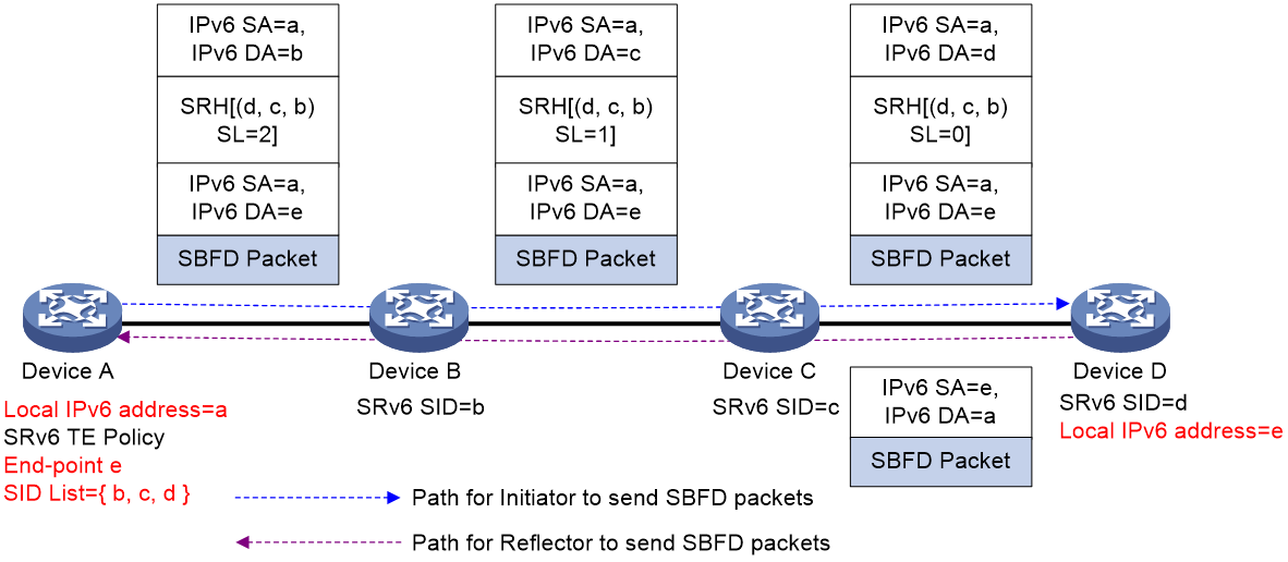
|
|
NOTE: Because SBFD responses are forwarded according to the IPv6 routing table lookup, all SBFD sessions for the SRv6 TE policies that have the same source and destination nodes use the same path to send responses. A failure of the SBFD response path will cause all the SBFD sessions to be down and packets cannot be forwarded through the SRv6 TE policies. |
BFD/SBFD No-Bypass
When you use BFD or SBFD to detect the connectivity of an SRv6 TE policy, the following conditions might exist:
· All SID lists for the primary candidate path fail.
· A local protection path (for example, a backup path calculated with TI-LFA) is available.
In this situation, all the BFD/SBFD packets will be forwarded through the local protection path. The BFD/SBFD session and primary candidate path will remain in up status, and traffic will be forwarded through the local protection path.
In certain scenarios, the local protection path might have unstable bandwidth and delay issues and fail to meet specific service requirements. In this case, the local protection path can only be used to protect traffic temporarily. When you enable the BFD No-Bypass feature, if all SID lists for the primary candidate path fail, the local protection path does not forward BFD/SBFD packets. The associated BFD/SBFD session then goes down, and the primary candidate path goes down as a result. Traffic will switch over to the backup candidate path or another SRv6 TE policy for forwarding. The BFD No-Bypass feature prevents traffic from being forwarded through the local protection path for a long time.
SBFD for SRv6 TE policy by using specific reverse path
By default, the SBFD return packets used for SRv6 TE policy connectivity detection are forwarded based on the IP forwarding path. If a transit node fails, all the return packets will be discarded, and the SBFD sessions will go down as a result. If multiple SRv6 TE policies exist between the source and endpoint nodes, SBFD will mistakenly determine that the SID lists of all SRv6 TE policies are faulty.
To resolve this issue, you can enable SBFD return packets to be forwarded based on the specified SID list. Generally for SRv6 TE policies, the path specified for SBFD return packets (reverse path) is consistent with the path for forwarding SBFD packets (forward path). This scenario is known as SBFD forward and reverse path consistency.
You can specify the SBFD reverse path by specifying a reverse BSID or a path segment (End.PSID).
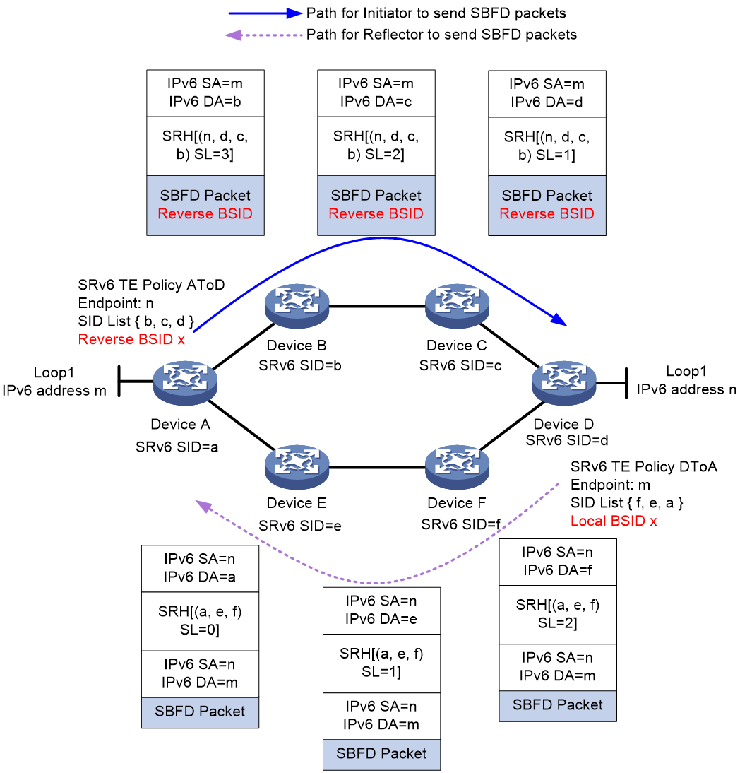
As shown in Figure 18, the reverse BSID method is implemented as follows (using the Insert encapsulation mode):
1. Create an SRv6 TE policy on both Device A and Device D, named AtoD and DtoA, respectively. The forwarding path for SRv6 TE policy AtoD is A > B > C > D and that for SRv6 TE policy DtoA is D > F > E > A. On Device D, assign local BSID x to SID list D > F > E > A.
2. Enable SBFD for SRv6 TE policy AtoD on Device A, and set the reverse BSID for SBFD return packets to x, which is the same as the local BSID specified on Device D. When Device A sends an SBFD packet, it encapsulates an Aux Path TLV (TLV for the backup path) in the packet, which includes the reverse BSID.
3. When Device D receives the SBFD packet, it compares the reverse BSID in the packet with the local BSID. If they are the same, Device D re-encapsulates the IPv6 header and SRH for the return SBFD packet, where the SRH contains the SID list associated with the local BSID.
4. The return packet will then follow path D > F > E > A in the SID list back to Device A.
Figure 18 SBFD for SRv6 TE policy by using specific reverse path (reverse BSID)
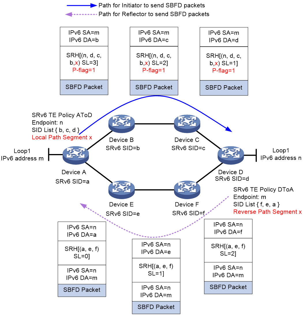
As shown in Figure 19, the path segment (End.PSID) method is implemented as follows (using the Insert encapsulation mode):
Create an SRv6 TE policy on both Device A and Device D, named AtoD and DtoA, respectively. The forwarding path for SRv6 TE policy AtoD is A > B > C > D and that for SRv6 TE policy DtoA is D > F > E > A. On Device D, assign reverse path segment x to SID list D > F > E > A.
On Device A, enable SBFD for SRv6 TE policy AtoD, and set the local path segment for SBFD return packets to x, which is the same as the reverse path segment specified on Device D. When Device A sends an SBFD packet, it sets the fifth bit of the Flags field in the SRH header, known as the P-flag, to indicate that the SRH header carries a path segment. Then, it encapsulates the local path segment (End.PSID) into the SRH header, at the SRH[SL +1] position in the SID list.
After Device D receives the SBFD packet and finds that the P-flag is set, it retrieves the path segment information from the packet. On Device D, the reverse path segment value specified for local SID list D > F > E > A is the same as the path segment value in the SRH header of the received packet. Therefore, Device D decapsulates the packet and re-encapsulates an IPv6 header and SRH for the return SBFD packet, where the SRH contains the SID list associated with the reverse path segment.
The return packet will then follow path D > F > E > A in the SID list back to Device A.
Figure 19 SBFD for SRv6 TE policy by using specific reverse path (path segment)
BFD for SRv6 TE policy by using specific reverse path
By default, the BFD return packets used for SRv6 TE policy connectivity detection are forwarded based on the IP forwarding path. If a transit node fails, all the return packets will be discarded, and the BFD sessions will go down as a result. If multiple SRv6 TE policies exist between the source and endpoint nodes, BFD will mistakenly determine that the SID lists of all SRv6 TE policies are faulty.
To resolve this issue, you can enable the return packets for BFD echo packets to be forwarded based on the specified SID list. Generally for SRv6 TE policies, the path specified for BFD echo return packets (reverse path) is consistent with the path for forwarding BFD echo packets (forward path). This scenario is known as BFD forward and reverse path consistency.
You can specify the BFD reverse path by using the following methods:
· Specifying a reverse BSID
· Specifying an End.XSID.
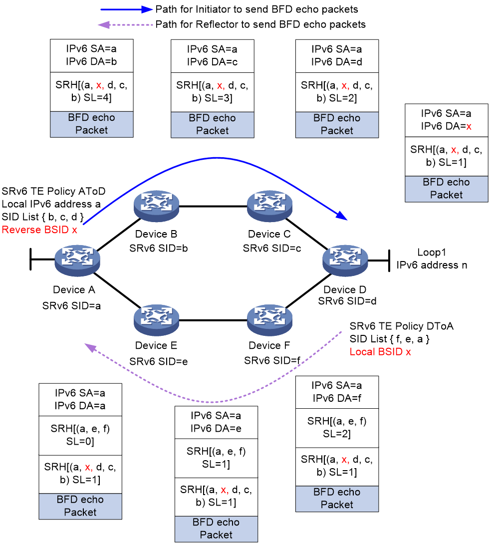
As shown in Figure 20, the reverse BSID method is implemented as follows (using the Insert encapsulation mode):
1. Create an SRv6 TE policy on both Device A and Device D, named AtoD and DtoA, respectively. The forwarding path for SRv6 TE policy AtoD is A > B > C > D and that for SRv6 TE policy DtoA is D > F > E > A. On Device D, assign local BSID x to SID list D > F > E > A.
2. Enable echo BFD for SRv6 TE policy AtoD on Device A, and set the reverse BSID for BFD echo return packets to x, which is the same as the local BSID specified on Device D. When Device A sends a BFD echo packet, it encapsulates the reverse BSID into the SRH header, at the SRH[1] position in the SID list.
3. When Device D receives the BFD echo packet, it finds that SL is 1 and the destination address is x in the packet. The destination address x is the same as the local BSID specified for the local SID list D > F > E > A. As a result, Device D inserts a new SRH into the BFD echo return packet, carrying the SID list associated with the local BSID.
4. The return packet will then follow path D > F > E > A in the SID list back to Device A.
Figure 20 BFD for SRv6 TE policy by using specific reverse path (reverse BSID)
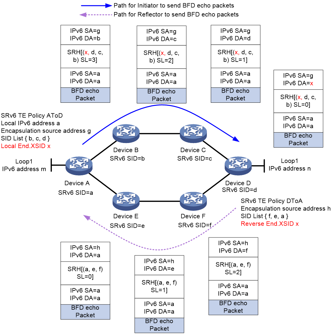
As shown in Figure 21, the End.XSID method is implemented as follows (using the Encaps encapsulation mode):
1. Create an SRv6 TE policy on both Device A and Device D, named AtoD and DtoA, respectively. The forwarding path for SRv6 TE policy AtoD is A > B > C > D and that for SRv6 TE policy DtoA is D > F > E > A. On Device D, assign reverse End.XSID x for SID list D > F > E > A.
2. Enable echo BFD for SRv6 TE policy AtoD on Device A, and set the local End.XSID for BFD echo return packets to x, which is the same as the reverse BSID specified on Device D. When Device A sends a BFD echo packet, it encapsulates a new IPv6 header and SRH header outside the BFD echo packet header, where the SRH contains the local End.XSID at the SRH[0] position in the SID list.
3. When Device D receives the BFD echo packet, it finds that SL is 0 and the destination address is x in the packet. The destination address x is the same as the reverse End.XSID specified for the local SID list D > F > E > A. As a result, Device D executes the forwarding behavior of the reverse End.XSID: decapsulates the IPv6 and SRH headers of the BFD echo packet, and then encapsulates the packet with a new IPv6 header and SRH extension header, which carries the SID list associated with reverse End.XSID.
4. The return packet will then follow path D > F > E > A in the SID list back to Device A.
Figure 21 BFD for SRv6 TE policy by using specific reverse path (End.XSID).
BFD down triggering candidate path reselection for an SRv6 TE policy
This feature enables collaboration between the BFD scheme and hot standby scheme for an SRv6 TE policy. It allows BFD session down events to trigger candidate path reselection for SRv6 TE policies.
By default, when the SRv6 TE policy has multiple valid candidate paths, the following conditions exist:
· If the hot standby feature is disabled, BFD or SBFD detects all SID lists for only the optimal valid candidate path of the SRv6 TE policy. The device establishes a separate BFD or SBFD session for each SID list. When all BFD or SBFD sessions go down, the SRv6 TE policy will not select other valid candidate paths, and the device will not forward packets through the SRv6 TE policy.
· If the hot standby feature is enabled, BFD or SBFD detects all SID lists for the primary and backup paths of the SRv6 TE policy. The device establishes a separate BFD or SBFD session for each SID list.
¡ If all BFD or SBFD sessions for the primary path go down, the SRv6 TE policy will use the backup path to forward packets without reselecting other valid candidate paths.
¡ If all BFD or SBFD sessions for the primary and backup paths go down, the SRv6 TE policy will not select other valid candidate paths, and the device will not forward packets through the SRv6 TE policy.
If you enable BFD session down events to trigger SRv6 TE policy path reselection, the following conditions exist when the SRv6 TE policy has multiple valid candidate paths:
· If the hot standby feature is disabled, BFD or SBFD detects all SID lists for only the optimal valid candidate path of the SRv6 TE policy. The device establishes a separate BFD or SBFD session for each SID list. When all BFD or SBFD sessions go down, the SRv6 TE policy will reselect another valid candidate path for packet forwarding. If no valid candidate paths are available for the SRv6 TE policy, the device cannot forward packets through the SRv6 TE policy.
· If the hot standby feature is enabled, BFD or SBFD detects all SID lists for the primary and backup paths of the SRv6 TE policy. The device establishes a separate BFD or SBFD session for each SID list.
¡ If all BFD or SBFD sessions for the primary path go down, the SRv6 TE policy will use the backup path to forward packets, and reselect the primary and backup paths.
¡ If all BFD or SBFD sessions for the primary and backup paths go down, the SRv6 TE policy will reselect other valid candidate paths as the primary and backup paths. The device will forward packets through the new primary path of the SRv6 TE policy.
¡ During optimal path reselection, if no valid candidate paths are available for the SRv6 TE policy, the device cannot forward packets through the SRv6 TE policy.
SRv6 TE policy transit node protection
Protection path failure
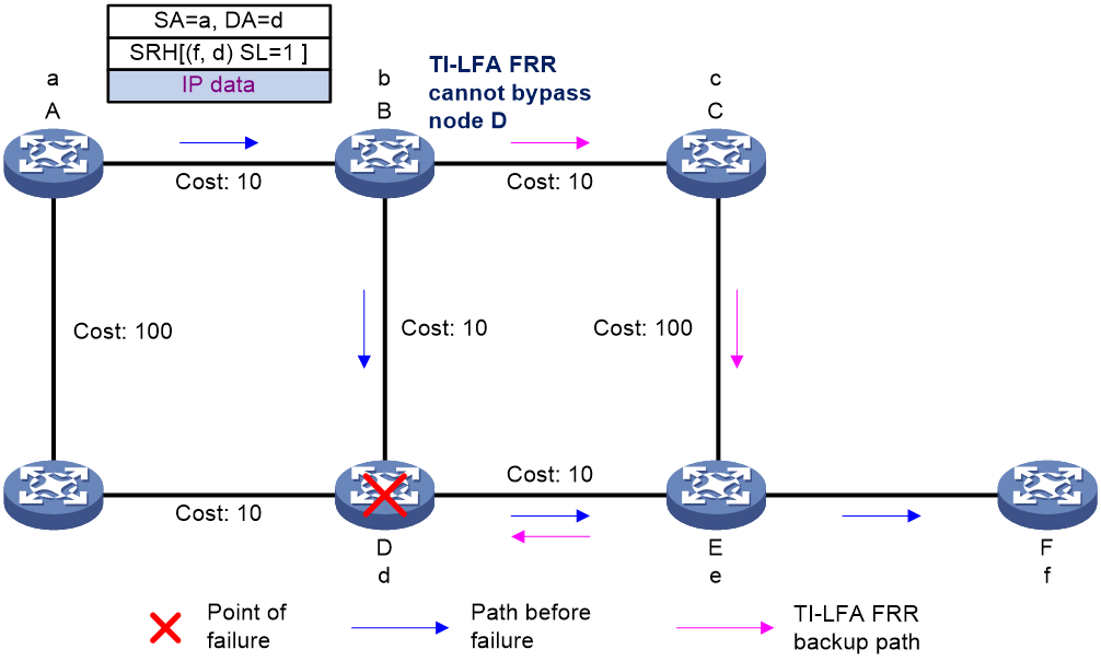
The SID list of an SRv6 TE policy specifies the nodes or links that packets must traverse. As shown in Figure 22, node A forwards packets to node F through an SRv6 TE policy. The SID list of the optimal candidate path contains the End.SIDs of node D and egress node F. Therefore, the packet arrives at node D before reaching egress node F. If TI-LFA FRR is enabled on node B and node D fails, the backup path calculated by TI-LFA FRR will still use the End.SID of node D as destination. As a result, the backup path cannot bypass node D and thus cannot provide service protection.
Figure 22 Protection path failure
Transit node protection (SRv6 TE FRR)
To resolve the protection path failure caused by strict node constraints in an SRv6 TE policy, SRv6 TE FRR is introduced.
After SRv6 TE FRR is enabled, when a transit node of an SRv6 TE policy fails, the upstream node (enabled with SRv6 TE FRR) of the faulty node can take over to forward packets. The upstream node is called a proxy forwarding node. During proxy forwarding, the faulty node is bypassed by traffic.
After SRv6 TE FRR is enabled on a node, upon receiving a packet that contains an SRH and the SL in the SRH is greater than 0 (SL>0), the node will act as a proxy forwarding node in any of the following scenarios:
· The node does not find a matching forwarding entry in the IPv6 FIB.
· The next hop address of the packet is the destination address of the packet, and the outgoing interface for the destination address is in DOWN state.
· The matching local SRv6 SID is an END.X SID, and the outgoing interface for the END.X SID is in DOWN state.
· The outgoing interface in the matching route is NULL0.
A proxy forwarding node forwards packets as follows:
· Decrements the SL value in the SRH of a packet by 1.
· Copies the next SID to the DA field in the outer IPv6 header, so as to use the SID as the destination address of the packet.
· Looks up the forwarding table by the destination address and then forwards the packet.
In this way, the proxy forwarding node bypasses the fault node. This transit node failure protection technology is referred to as SRv6 TE FRR.
Figure 23 SRv6 TE FRR for transit node failure protection
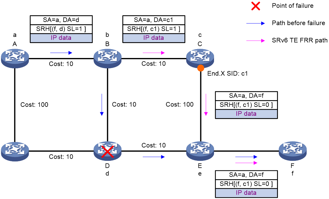
As shown in Figure 23, after a packet is steered into an SRv6 TE policy, the packet is forwarded as instructed by the SID list {d, f}.
When node D fails, the node failure protection process is as follows:
1. Upstream node B detects that the next hop of the packet is faulty. In this situation, the output interface for the destination address of the packet is in DOWN state, and the SL value is greater than 0. Therefore, node B performs the proxy forwarding behavior: Decrements the SL value by 1, copies the next SID to the DA field in the outer IPv6 header, and then forwards the packet according to the SID (destination address of the packet). Because the SL value is now 0, node B can remove the SRH and then search the corresponding table to forward the packet based on the destination address (f).
2. Node B forwards the packet as follows:
¡ If the route to node F is converged (the next hop in the route is node C), node B uses the converged shortest path to forward the packet to node C.
¡ If the route to node F is not converged (the primary next hop in the route is node D), node B uses the TI-LFA computed backup path to forward packet. The backup path's repair list is <c1>. Therefore, node B encapsulates an SRH to the packet to add backup path Segment List c1, and then forwards the packet over the backup path to node F.
Special processing on the source node
If source node A (ingress node) of the SRv6 TE policy detects the failure of node D (the first SID in the SID list is unreachable), node A then places the SRv6 TE policy to the down state. The device cannot forward packets through the SRv6 TE policy or trigger SRv6 TE FRR.
To resolve this issue, enable the bypass feature for the SRv6 TE policy on the source node. This feature enables the source node to generate a route that uses the first SID as the destination address and the NULL0 interface as the outgoing interface. The route ensures that the SRv6 TE policy is in up state when the first SID is unreachable, so as to trigger SRv6 TE FRR.
After node A triggers SRv6 TE FRR, node A decrements the SL value by 1, copies the next SID (f) to the DA field in the outer IPv6 header, and then forwards the packet to node B according to the SID (destination address of the packet).
When node B receives the packet, it processes the packet as follows:
· If the route to node F is converged (the next hop in the route is node C), node B uses the converged shortest path to forward the packet to node C.
· If the route to node F is not converged (the primary next hop in the route is node D), node B uses the TI-LFA computed backup path to forward the packet to node F.
SRv6 egress protection
This feature provides egress node protection in IP L3VPN over SRv6, EVPN L3VPN over SRv6, EVPN VPLS over SRv6, EVPN VPWS over SRv6, or IP public network over SRv6 networks where the public tunnel is an SRv6 TE policy tunnel.
SRv6 TE policy egress protection applies only to the dual homing scenario where a CE is dual-homed to PEs. To implement SRv6 TE policy egress protection, the egress node and the protected egress node must have the same forwarding entries.
|
|
IMPORTANT: · SRv6 TE policy egress protection is not supported in EVPN VPLS over SRv6 and EVPN VPWS over SRv6 networks if dual homing is configured in the networks and the redundancy mode is single-active. · In addition to scenarios where SRv6 TE policies act as tunnels, SRv6 TE policy egress protection also takes effect on scenarios where SRv6 BE-based forwarding is used. |
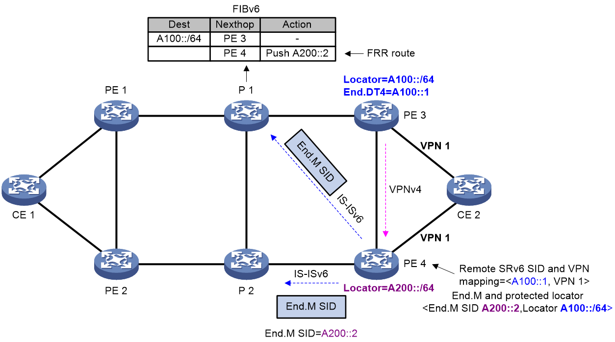
As shown in Figure 24, an SRv6 TE policy is deployed between PE 1 and PE 3. PE 3 is the egress node (endpoint node) of the SRv6 TE policy. To improve forwarding reliability, CE 2 is dual-homed to PE 3 and PE 4, and PE 4 is enabled to protect PE 3.
Figure 24 SRv6 TE policy egress protection
End.M SID
In SRv6 TE policy egress protection, an End.M SID is used to protect the SRv6 SIDs in a specific locator. If an SRv6 SID advertised by the remote device (PE 3 in this example) is within the locator, the protection node (PE 4) uses the End.M SID to protect that SRv6 SID (remote SRv6 SID).
PE 4 takes different actions as instructed by an End.M SID in different network scenarios:
· IP/EVPN L3VPN/IP public network over SRv6 TE policy scenario
a. Removes the outer IPv6 header to obtain the remote SRv6 SID from the inner packet.
b. Searches the remote SRv6 SID and VPN/public instance mapping table to find the VPN/public instance mapped to the remote SRv6 SID.
c. Forwards the packet by looking up the routing table of the VPN/public instance.
· EVPN VPWS over SRv6 TE policy scenario
a. Removes the outer IPv6 header to obtain the remote SRv6 SID from the inner packet.
b. Searches the remote SRv6 SID and cross-connect mapping table to find the cross-connect mapped to the remote SRv6 SID.
c. Forwards the packet to the AC associated with the cross-connect.
In this scenario, the remote SRv6 SID must be an End.DX2 SID.
· EVPN VPLS over SRv6 TE policy scenario
a. Removes the outer IPv6 header to obtain the remote SRv6 SID from the inner packet.
b. Searches the remote SRv6 SID and VSI mapping table to find the VSI mapped to the remote SRv6 SID.
c. Forwards the packet according to the MAC address forwarding table of the VSI.
In this scenario, the remote SRv6 SID must be an End.DT2U SID.
Remote SRv6 SID
As shown in Figure 24, PE 4 receives a BGP route from PE 3. If the SRv6 SID in the BGP route is within the locator protected by the End.M SID on PE 4, PE 4 regards the SRv6 SID as a remote SRv6 SID and generates a mapping between the remote SRv6 SID and the VPN instance, public instance, cross-connect, or VSI.
When the adjacency between PE 4 and PE 3 breaks, PE 4 deletes the BGP route received from PE 3. As a result, the remote SRv6 SID and VPN instance/public instance/cross-connect/VSI mapping will be deleted, resulting in packet loss. To avoid this issue, you can configure the mappings deletion delay time on PE 4 to ensure that traffic is forwarded through PE 4 before PE 1 knows the PE 3 failure and computes a new forwarding path.
Route advertisement
The route advertisement procedure is similar in IP L3VPN, EVPN L3VPN, EVPN VPWS, EVPN VPLS, or IP public network over SRv6 TE policy egress protection scenarios. The following example describes the route advertisement in an IP L3VPN over SRv6 TE policy egress protection scenario.
As shown in Figure 24, the FRR path is generated on P 1 as follows:
1. PE 4 advertises the End.M SID and the protected locator to P 1 through an IPv6 IS-IS route. Meanwhile, PE 4 generates a local SID entry for the End.M SID.
2. Upon receiving the route that carries the End.M SID and the protected locator, P 1 installs a Mirror FRR backup route into its routing table for the protected locator. The next hop of the route is PE 4. To ensure that traffic can bypass PE 3 and arrive at PE 4 without causing loops, the device must calculate a TI-LFA backup path and push the End.M SID to the end of the TI-LFA backup path's SID list.
On PE 4, a <remote SRv6 SID, VPN instance > mapping entry is generated as follows:
1. Upon receiving the private route from CE 2, PE 3 encapsulates the route as a VPNv4 route and sends it to PE 4. The VPNv4 route carries the SRv6 SID, RT, and RD information.
2. After PE 4 receives the VPNv4 route, it obtains the SRv6 SID and the VPN instance. Then, PE 4 performs longest matching of the SRv6 SID against the locators protected by End.M SIDs. If a match is found, PE 4 uses the SRv6 SID as a remote SRv6 SID and generates a <remote SRv6 SID, VPN instance> mapping entry.
Packet forwarding
The packet forwarding procedure is similar in IP L3VPN, EVPN L3VPN, EVPN VPWS, EVPN VPLS, or IP public network over SRv6 TE policy egress protection scenarios. The following example describes the packet forwarding in an IP L3VPN over SRv6 TE policy egress protection scenario.
Figure 25 Data forwarding in SRv6 TE policy egress protection
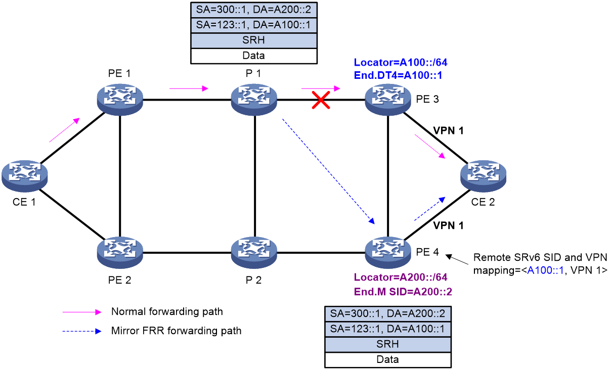
As shown in Figure 25, typically traffic is forwarded along the CE 1-PE 1-P 1-PE 3-CE 2 path. When the egress node PE 3 fails, a packet is forwarded as follows:
1. P 1 detects that its next hop (PE 3) is unreachable and thus switches traffic to the Mirror FRR path. In this example, the optimal path between P 1 and PE 4 does not traverse PE 3, and P 1 does not need to encapsulate the TI-LFA FRR SID list into the packet. Therefore, P 1 encapsulates the packet with an IPv6 header whose destination address is the End.M SID, and then forwards the packet to PE 4.
2. PE 4 finds that the packet is destined for its local End.M SID. As instructed by the End.M SID, PE 4 performs the following operations:
a. Removes the outer IPv6 header to obtain the remote SRv6 SID from the inner packet. (The remote SRv6 SID is A100::1 in this example)
b. Searches the remote SRv6 SID and VPN instance mapping table to find the VPN instance mapped to the remote SRv6 SID. (The VPN instance is VPN 1 in this example.)
c. Looks up the routing table of the VPN instance for a route to forward the packet to CE 2.
SRv6 TE policy application scenarios
SRv6 TE policy application in the APN6 network
About APN6
Application-aware IPv6 networking (APN6) is a new type of network. APN6 uses the Destination Option Header (DOH) in IPv6 packets to carry application information for the network to identify applications, perceive application requirements, and provide precise and differentiated network services for various application services.
IETF defines the DOH to carry the following application information:
· APN ID—ID of an application. A network device differentiates the service flows of different applications based on their APN IDs.
· APN parameters—Parameters that represent the network quality requirements of an application’s service flows, including bandwidth, latency, jitter, and packet loss rate. A network device uses these parameters to perceive the network quality requirements of the application's service flows.
In the APN6 network, you can apply the SRv6 TE policy, SRv6 network slicing, SRv6 SFC (or SRv6 service chain), and iFiT technologies for the device to flexibly select paths based on the application information in packets and monitor network quality for critical application services in real time. For more information about APN6, see APN6 configuration in Application-aware Networking Configuration Guide.
APN ID-based traffic forwarding
This section uses the IPv6 L3VPN over SRv6 TE policy network as an example to describe APN ID-based traffic forwarding in SRv6 TE policy scenarios, as shown in Figure 26.
Figure 26 Diagram for APN ID-based traffic forwarding
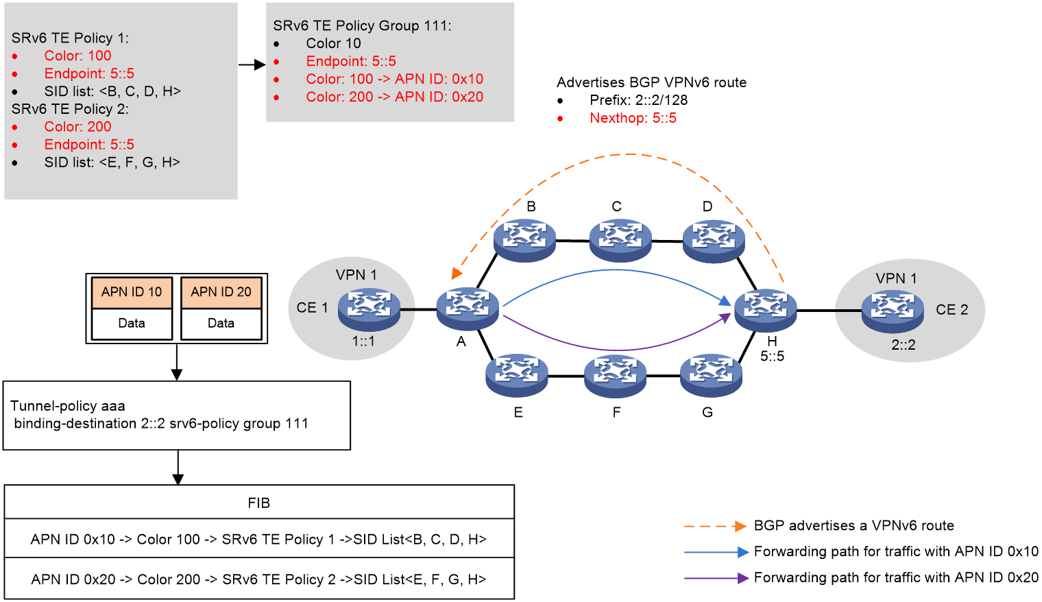
To achieve APN ID-based traffic steering, you can perform the following operations:
1. On Device A, add multiple SRv6 TE policies with different colors to the same SRv6 TE policy group, and then configure color-to-APN ID mappings for that SRv6 TE policy group.
2. Use one of the following methods to steer traffic to the SRv6 TE policy group:
¡ Bind the desired destination address to the SRv6 TE policy group in a tunnel policy. Traffic destined for the destination address will be steered to the SRv6 TE policy group for further forwarding.
¡ Set SRv6 TE policy group as the preferred tunnel type in a tunnel policy. When the next hop address of a route is the endpoint address of the SRv6 TE policy group, the device preferentially steers traffic to the SRv6 TE policy group.
¡ Recurse BGP routes that can match the SRv6 TE policy group to the SRv6 TE policy group. A BGP route can match an SRv6 TE policy group only if its color value and next hop address can match the color value and endpoint address of that SRv6 TE policy group.
3. In the SRv6 TE policy group, specify the forward type as APN ID-based forwarding and create mappings between APN IDs and forwarding policies. The device supports the following types of mappings:
¡ Color-to-APN ID mapping—Device A steers packets with a specific APN ID to the SRv6 TE policy associated with the color value mapped to that APN ID. As shown in Figure 26, APN 10 is mapped to SRv6 TE policy 1, and APN 20 is mapped to SRv6 TE policy 2. In this way, APN ID > color > SRv6 TE policy mappings are created, enabling APN ID-based traffic steering to the desired SRv6 TE policy.
¡ SRv6 BE-to-APN ID mapping—The device forwards packets with specific APN IDs in SRv6 BE mode. In SRv6 BE mode, Device A encapsulates the packets with a new IPv6 header. The destination address in the IPv6 header is the VPN SID that the egress node of the SRv6 TE policy group assigned to the public network or to a VPN instance. Then, the device looks up the IPv6 routing table for a matching route to forward the packets.
|
|
IMPORTANT: Compared with SRv6 BE-based forwarding, APN ID-based traffic forwarding has controllable paths and provides higher availability, and can be combined with iFIT measurement methods to detect the network quality of end-to-end fixed forwarding paths. As a best practice, use SRv6 TE policy tunnels to forward traffic for critical application services and use SRv6 BE forwarding to forward traffic for non-critical services or services without SLA requirements. In addition, you can specify SRv6 BE forwarding as a backup forwarding method for SRv6 TE policy-based forwarding. |
IPR for SRv6 TE policies
About this feature
As shown in Figure 27, establish an SRv6 TE policy group between two nodes in the network, which contains multiple SRv6 TE policy tunnels. The network quality of different SRv6 TE policy tunnels in the SRv6 TE policy group might vary and change in real time. You can use Intelligent Policy Route (IPR) to automatically switch over traffic in one forwarding path to another forwarding path based on the network quality of the SRv6 TE policy tunnels. IPR ensures that service traffic is always forwarded through a forwarding path that meets the network quality requirements.
The IPR feature of SRv6 TE policies uses the real-time network quality measurement capability of iFIT to evaluate the network quality of SRv6 TE policy tunnels. The feature excludes SRv6 TE policy tunnels that do not meet the network quality requirements based on the measurement results of iFIT, finds the SRv6 TE policy tunnel with the highest priority through calculation, and steers traffic to this SRv6 TE policy tunnel for forwarding.
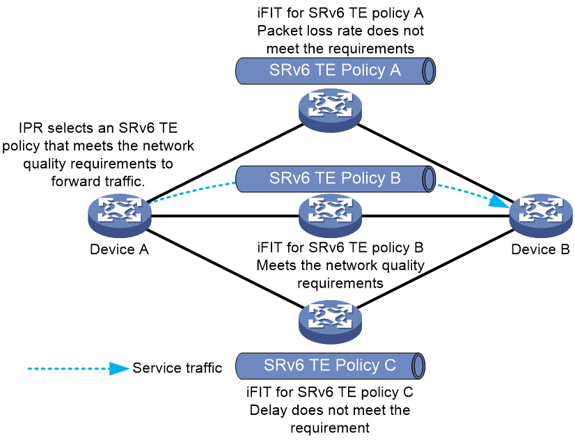
IPR operating mechanism
IPR is mainly accomplished through the collaboration of the following functions:
· The iFIT measurement function of SRv6 TE policies.
· The IPR path calculation function of SRv6 TE policies.
· The function of steering service traffic to an IPR policy.
IPR uses the following procedure to forward traffic:
1. Uses iFIT to measure the network quality of SRv6 TE policies.
As shown in Figure 28, configure iFIT on the source and egress nodes of each SRv6 TE policy to measure the end-to-end packet loss rate, delay, and jitter of each SRv6 TE policy. The source node analyzes and calculates the real-time packet loss rate, delay, and jitter data for each SRv6 TE policy. iFIT uses the following procedure to measure the network quality of an SRv6 TE policy:
a. The source node, which operates in analyzer operating mode, automatically creates an iFIT instance and assigns a flow ID to the instance.
b. Acts as the data sender, the source node encapsulates the original packets with the DOH header carrying the iFIT option field and the SRH header when it forwards the packets through the SRv6 TE policy. The iFIT option field contains a flow ID that identifies a target flow, the L bit (packet loss measurement color bit), the D bit (delay measurement color bit), and the measurement interval. The source node colors the L and D bits of the packets within an iFIT measurement interval. It then performs the following operations:
- Uses the color information of the packets to count the number of packets transmitted through the SRv6 TE policy within the measurement interval.
- Records the timestamps of the packets with the D bit set to 1 and sent through the SRv6 TE policy within the measurement interval.
c. Acts as the data receiver, the egress node, which operates in collector operating mode, parses the iFIT option field in packets to obtain iFIT measurement information (including the measurement interval) for the SRv6 TE policy. It then performs the following operations:
- Uses the color information of the packets to count the number of packets received through the SRv6 TE policy within the measurement interval.
- Records the timestamps of the packets with the D bit set to 1 and received through the SRv6 TE policy within the measurement interval.
d. The egress node performs the following operations:
- Establishes a UDP session with the source node through the source address of the received packets.
- Returns the packet count statistics and packet timestamps to the source node through the UDP session according to the iFIT measurement interval of the SRv6 TE policy.
e. The source node analyzes and calculates the packet loss rate, delay, and jitter of the packets forwarded through the SRv6 TE policy.
Figure 28 iFIT measurement diagram
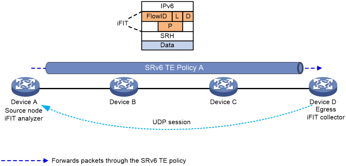
2. Uses IPR path calculation for path selection and switchover.
As shown in Figure 29, the source node of SRv6 TE policies periodically calculates the current optimal SRv6 TE policy based on the following items:
¡ The packet loss rate, delay, and jitter data measured by iFIT for different SRv6 TE policies.
¡ The path selection priority of each SRv6 TE policy.
IPR path calculation requires IPR policies. An IPR policy is an SLA-based policy for selecting the optimal SRv6 TE policy. You can define the following contents in an IPR policy:
¡ SLA thresholds for service traffic, including the delay threshold, packet loss rate threshold, jitter threshold, and Composite Measure Indicator (CMI) threshold. CMI is calculated by using the following formula: CMI = delay (ms) + jitter (ms) + packet loss rate (‰).
¡ Mappings between color attribute values of SRv6 TE policies and path selection priority values. The smaller the value, the higher the priority.
¡ Switchover period between SRv6 TE policies and WTR period.
The operating mechanism for IPR path calculation is as follows:
a. The source node periodically performs path calculation according to the IPR calculation period. When calculating the optimal SRv6 TE policy, it first measures whether the delay, packet loss rate, jitter, and CMI values of each SRv6 TE policy cross the SLA thresholds defined in an IPR policy. If any of the values crosses an SLA threshold, the source node does not use the SRv6 TE policy as a candidate forwarding path to participate in optimal SRv6 TE policy selection. If iFIT fails to measure the delay, packet loss rate, jitter, and CMI values of an SRv6 TE policy, but the SRv6 TE policy is valid, it can still be used as a candidate path for path selection.
b. The source node selects the SRv6 TE policy with the smallest path selection priority value from the candidate SRv6 TE policies as the optimal SRv6 TE policy. If multiple SRv6 TE policies have the same path selection priority, they can load share traffic.
c. When the source node of SRv6 TE policies calculates a different optimal SRv6 TE policy than the one currently used by a service, it does not immediately switch over the traffic of that service to the new optimal SRv6 TE policy. Instead, it waits for a switchover period. This mechanism prevents SRv6 TE policy flapping from causing frequent forwarding path switchover for service traffic.
Figure 29 Diagram for IPR path calculation
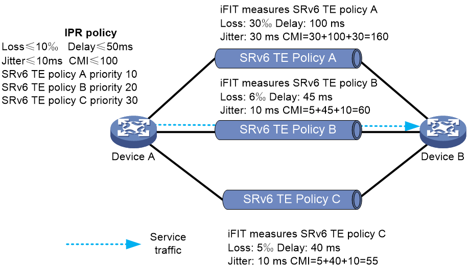
3. Steers service traffic to an IPR policy as follows:
a. Uses one of the following methods to obtain an SRv6 TE policy group for traffic steering:
- Matches the destination IP address in a packet with a tunnel policy associated with an SRv6 TE policy group.
- Searches for an SRv6 TE policy group with color and endpoint address matching the color extended community attribute and next hop in a BGP route, and recurses the BGP route to the SRv6 TE policy group.
b. Configure TE class ID-based traffic steering for the SRv6 TE policy group.
c. Configure mappings between TE class IDs and IPR policies. The optimal SRv6 TE policy is dynamically selected from the SRv6 TE policy group for forwarding service traffic.
SRv6 TE policy application in the ARN network
About ARN
Application Responsive Network (ARN) is a novel network architecture designed to provide personalized network services. The design philosophy of ARN focuses on the following principles:
· Open and programmable network capabilities: ARN emphasizes opening programming interfaces in the data plane, allowing applications to call network resources similarly to calling operating systems. This approach aims to meet the diverse network demands of users by providing stable and high-speed connections. Meanwhile, it can ensure service quality by allowing applications to call network services on a per packet type basis.
· Decoupling of IP address and service: In traditional networks, IP addresses and services are tightly bound. As the number of user applications grows, network management gets increasingly complex. By decoupling IP addresses and services, ARN allows network management and optimization based on the characteristics and demands of user applications. With ARN, network configuration and management are simplified, because multidimensional forwarding services are available.
· Decoupling of network and application: ARN introduces an ARN layer between the network and applications. With this layer, the network does not need to directly perceive the diversity of applications. Meanwhile, this layer also protects the privacy of applications and internal network information. Access control and a token-based calling mechanism are implemented based on ARN encapsulation, which is similar to software programming.
· Abstraction of network resources: To meet the demands for personalized and diversified network services, ARN uses ARN IDs to represent network resources. This approach reduces the complexity of resource identifiers in the data plane and simplifies network operation and deployment. The introduction of ARN IDs simplifies network resource identification and promotes efficient resource usage, because the network does not require excessive resource identifiers or complex ACL-based data filtering. The current software version supports the following ARN ID categories:
¡ Network ARN ID: Identifies the massive users and their services attached to edge devices in metropolitan area networks (MAN).
¡ Resource ARN ID: Identifies the network resources and service standards required by applications and services. Based on the required network resources and service standards, edge devices in the backbone network can aggregate application services with different network ARN IDs, and map them to the same resource ARN ID.
The design philosophy of ARN aims to provide more personalized, flexible, and efficient network services. With ARN, applications can access network resources as conveniently as accessing operating systems, meeting the diverse network service demands of users in today's digital world.
IPv6 packet encapsulation with ARN IDs
To support ARN, extensions have been made in the IPv6 data plane. The ARN ID option is encapsulated in the Destination Option Header (DOH) of IPv6 packets. In most cases, this option is transparent to transit nodes along the forwarding path. Only the destination node can read this option from the DOH.
Figure 30 shows the format of the ARN ID option encapsulated in a DOH.
Figure 30 Format of the ARN ID option
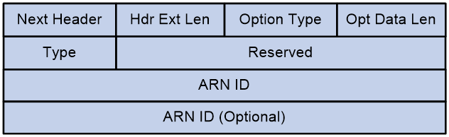
Table 1 Fields in the ARN ID option
|
Field |
Length |
Description |
|
8 bits |
Next extension header. |
|
|
Hdr Ext Len |
8 bits |
Length of the extension header. |
|
Option Type |
8 bits |
Type of the option. The value is 0x40 for the ARN ID option. |
|
Opt Data Len |
8 bits |
Length of the ARN ID option. |
|
Type |
8 bits |
Type of the ARN ID option: · 0—Reserved. · 1—The option only contains network ARN IDs. · 2—The option contains both network ARN IDs and resource ARN IDs. · 3—The option only contains resource ARN IDs. |
|
Reserved |
24 bits |
Reserved portion. |
|
ARN ID |
32 bits |
· If the Type field is 1 or 2, this field is a list of network ARN IDs. · If the Type field is 3, this field is a list of resource ARN IDs. |
|
ARN ID (Optional) |
32 bits |
If the Type field is 2, this field is a list of network ARN IDs. |
ARN ID-based traffic forwarding
Figure 31 shows the process of ARN ID-based traffic steering in an IPv6 L3VPN over SRv6 TE Policy network.
Figure 31 ARN ID-based traffic forwarding
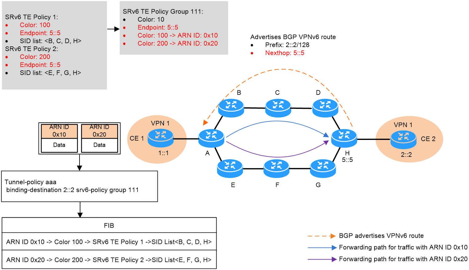
To achieve ARN ID-based traffic steering, you can perform the following operations:
1. On Device A, add multiple SRv6 TE policies with different colors to the same SRv6 TE policy group, and then configure color-to-ARN ID mappings for that SRv6 TE policy group.
2. Use one of the following methods to steer traffic to the SRv6 TE policy group:
¡ Bind the desired destination address to the SRv6 TE policy group in a tunnel policy. Traffic destined for the destination address will be steered to the SRv6 TE policy group for further forwarding.
¡ Set SRv6 TE policy group as the preferred tunnel type in a tunnel policy. When the next hop address of a route is the endpoint address of the SRv6 TE policy group, the device preferentially steers traffic to the SRv6 TE policy group.
¡ Recurse BGP routes that can match the SRv6 TE policy group to the SRv6 TE policy group. A BGP route can match an SRv6 TE policy group only if its color value and next hop address can match the color value and endpoint address of that SRv6 TE policy group.
3. In the SRv6 TE policy group, specify the forward type as ARN ID-based forwarding and create mappings between ARN IDs and forwarding policies. The device supports the following types of mappings:
¡ Color-to-ARN ID mapping—Device A steers packets with a specific ARN ID to the SRv6 TE policy associated with the color value mapped to that ARN ID. As shown in Figure 31, ARN 10 is mapped to SRv6 TE policy 1, and ARN 20 is mapped to SRv6 TE policy 2. In this way, ARN ID > color > SRv6 TE policy mappings are created, enabling ARN ID-based traffic steering to the desired SRv6 TE policy.
¡ SRv6 BE-to-ARN ID mapping—The device forwards packets with specific ARN IDs in SRv6 BE mode. In SRv6 BE mode, Device A encapsulates the packets with a new IPv6 header. The destination address in the IPv6 header is the VPN SID that the egress node of the SRv6 TE policy group assigned to the public network or to a VPN instance. Then, the device looks up the IPv6 routing table for a matching route to forward the packets.
Configuring SRv6 TE policies
Restrictions and guidelines: SRv6 TE policy configuration
The SRv6 TE policy candidate paths do not support SID lists calculated by PCE. The PCE-related feature of SRv6 TE policy candidate path reoptimization is not supported.
SRv6 TE policy tasks at a glance
To configure an SRv6 TE policy, perform the following tasks:
1. Configuring an SRv6 TE policy and configure basic settings for the policy:
This task is required when you use PCE to compute SID lists.
c. Configuring a candidate path and the SID lists of the path
d. (Optional.) Enabling strict SID encapsulation for SID lists
e. (Optional.) Configuring dynamic path calculation timers
f. (Optional.) Enabling the device to distribute SRv6 TE policy candidate path information to BGP-LS
g. (Optional.) Shutting down an SRv6 TE policy
2. (Optional.) Configuring BGP to advertise BGP IPv6 SR policy routes
a. Enabling BGP to advertise BGP IPv6 SR policy routes
b. Configuring BGP to redistribute BGP IPv6 SR policy routes
c. (Optional.) Enabling advertising BGP IPv6 SR policy routes to EBGP peers
d. (Optional.) Enabling Router ID filtering
e. (Optional.) Enabling validity check for BGP IPv6 SR policy routes
f. (Optional.) Configuring BGP to control BGP IPv6 SR policy route selection and advertisement
g. (Optional.) Maintaining BGP sessions
3. Configuring SRv6 TE policy traffic steering
4. (Optional.) Configuring the SRv6 TE policy encapsulation mode
5. (Optional.) Configuring IPR for SRv6 TE policies
6. (Optional.) Configuring high availability features for SRv6 TE policy
¡ Enabling SBFD for SRv6 TE policies
¡ Enabling echo BFD for SRv6 TE policies
¡ Enabling the No-Bypass feature for SRv6 TE policies
¡ Enabling BFD No-Bypass for SRv6 TE policies
¡ Enabling hot standby for SRv6 TE policies
¡ Configuring path switchover and deletion delays for SRv6 TE policies
¡ Setting the delay time for bringing up SRv6 TE policies
¡ Configuring path connectivity verification for SRv6 TE policies
¡ Configuring SRv6 TE policy transit node protection
¡ Configuring SRv6 TE policy egress protection
¡ Configuring candidate path reoptimization for SRv6 TE policies
¡ Configuring flapping suppression for SRv6 TE policies
7. (Optional.) Configuring advanced settings for SRv6 TE policies
¡ Configuring the TTL processing mode of SRv6 TE policies
¡ Configuring SRv6 TE policy CBTS
¡ Configuring a rate limit for an SRv6 TE policy
¡ Enabling the device to drop traffic when an SRv6 TE policy becomes invalid
¡ Specifying the packet encapsulation type preferred in optimal route selection
8. (Optional.) Maintaining an SRv6 TE policy
¡ Configuring SRv6 TE policy resource usage alarm thresholds
¡ Enabling SRv6 TE policy logging
¡ Enabling SNMP notifications for SRv6 TE policies
¡ Configuring traffic forwarding statistics for SRv6 TE policies
Creating an SRv6 TE policy
Manually creating an SRv6 TE policy and configuring its attributes
About this task
An SRv6 TE policy is identified by a headend, color, and endpoint.
You can bind a BSID to the policy manually, or set only the color and end-point attributes of the policy so the system automatically assigns a BSID to the policy. If you use both methods, the manually bound BSID takes effect.
Restrictions and guidelines
The configured BSID must be on the locator specified for SRv6 TE policies in SRv6 TE view. For more information about the locator configuration, see SRv6 configuration in Segment Routing Configuration Guide.
Different SRv6 TE policies cannot have the same color and end-point configuration.
When a BSID carries the COC and NEXT flavors or only the NEXT flavor, it can be encapsulated into SRv6 packet headers as a 16-bit G-SID, which shortens SRv6 packet headers.
Support for BSID flavors varies by locator type. When you use the binding-sid command to specify flavors for a BSID, follow these restrictions and guidelines:
· Make sure the locator specified in the srv6-policy locator command meets the related requirements. For example:
¡ The coc-next keyword is available only if the specified locator is a COC16 locator in default mode.
¡ The next keyword is available only if the specified locator is a COC16 locator.
· If the specified locator is a COC16 locator in W-LIB mode, you must specify the next keyword to ensure successful BSID assignment.
Procedure
1. Enter system view.
system-view
2. Enter SRv6 view.
segment-routing ipv6
3. Enter SRv6 TE view.
traffic-engineering
4. Specify a locator for SRv6 TE.
srv6-policy locator locator-name [ coc-next | next ]
By default, no locator is specified for SRv6 TE.
5. Enter SRv6 TE policy view.
policy policy-name
6. Configure a BSID for the policy.
binding-sid ipv6 ipv6-address [ coc-next | next ]
7. Set the color and endpoint attributes.
color color-value end-point ipv6 ipv6-address
By default, the color and endpoint attributes of an SRv6 TE policy are not configured.
Automatically creating SRv6 TE policies by using ODN
About this task
When the device receives a BGP route, if the color extended attribute value of the BGP route is the same as the color value of an ODN template, the device automatically creates an SRv6 TE policy and two candidate paths for the policy. The automatically created candidate paths use preferences 100 and 200.
You can specify an IPv6 prefix list to filter BGP routes. The BGP routes permitted by the specified IPv6 prefix list can trigger ODN to create SRv6 TE policies. The BGP routes denied by the specified IPv6 prefix list cannot trigger ODN to create SRv6 TE policies.
An ODN-created SRv6 TE policy is deleted immediately when the matching BGP route is deleted. To avoid packet loss before the new forwarding path is computed, you can configure a proper deletion delay time for the SRv6 TE policy.
Restrictions and guidelines
You need to configure candidate paths for an ODN-created SRv6 TE policy.
· For the ODN-created candidate path that uses preference 200, SID lists are dynamically calculated through the Affinity attribute or the Flex-Algo algorithm.
· For the ODN-created candidate path that uses preference 100, use PCE to compute the SID lists for the candidate path.
· Manually create candidate paths that use preferences other than 100 and 200, and then configure the SID lists for the candidate paths.
Procedure
1. Enter system view.
system-view
2. Enter SRv6 view.
segment-routing ipv6
3. Enter SRv6 TE view.
traffic-engineering
4. Specify a locator for SRv6 TE.
srv6-policy locator locator-name
By default, no locator is specified for SRv6 TE.
5. Create an ODN template and enter SRv6 TE ODN view.
on-demand color color-value
6. (Optional.) Configure the ODN SRv6 TE policy generation policy.
restrict prefix-list-name
By default, a BGP route can trigger ODN to create an SRv6 TE policy when the route's color attribute value is the same as the ODN color.
7. (Optional.) Configure the deletion delay time for ODN-created SRv6 TE policies.
delete-delay delay-time
By default, the deletion delay time for ODN-created SRv6 TE policies is 180000 milliseconds.
Configuring a PCEP session
Restrictions and guidelines
For more information about the PCEP commands, see MPLS TE commands in MPLS Command Reference.
Discovering PCEs
About this task
You can manually specify a PCE by using the pce static command on a PCC. A PCC sends PCEP connection requests to the discovered PCEs but does not accept requests from the PCEs.
Procedure
1. Enter system view.
system-view
2. Enter PCC view.
pce-client
3. Specify the IP address of the PCE.
pce static ip-address
Enabling the SRv6 capability for a PCC
Abou this task
To establish a PCEP session that supports SRv6, you need to enable the SRv6 capability on the devices at both sides of the PCEP session.
Procedure
1. Enter system view.
system-view
2. Configure the TE IPv6 router ID of the device.
te ipv6-router-id router-id
By default, the TE IPv6 router ID is not configured.
The TE IPv6 router ID is used to identify the source node in PCE requests. The TE IPv6 router ID of a device must be unique on the IPv6 network.
3. Enter PCC view.
pce-client
4. Enable the SRv6 capability for the PCC device.
pce capability segment-routing ipv6
By default, a PCC device does not have the SRv6 capability.
Configuring PCEP session parameters
About this task
This task allows you to configure parameters for a PCC to establish PCEP sessions to manually specified PCEs.
Procedure
1. Enter system view.
system-view
2. Enter PCC view.
pce-client
3. Set the path computation request timeout time.
pce request-timeout value
By default, the request timeout time is 10 seconds.
4. Set the PCEP session dead timer.
pce deadtimer value
By default, the PCEP session deadtimer is 120 seconds.
5. Set the keepalive interval for PCEP sessions.
pce keepalive interval
By default, the keepalive interval is 30 seconds.
6. Set the minimum acceptable keepalive interval and the maximum number of allowed unknown messages received from the PCE peer.
pce tolerance { min-keepalive value | max-unknown-messages value }
By default, the minimum acceptable keepalive interval is 10 seconds, and the maximum number of allowed unknown messages in a minute is 5.
7. Configure PCEP session authentication for a peer. Choose one option as needed:
¡ Configure the keychain authentication.
pce peer ip-address keychain keychain-name
¡ Configure the MD5 authentication.
pce peer ip-address md5 { cipher | plain } string
By default, PCEP session authentication is not configured.
For two devices to establish a PCEP session, you must configure the same authentication mode and specify the same key string on both devices.
Configuring a candidate path and the SID lists of the path
Restrictions and guidelines
Do not configure an SRv6 TE policy candidate path to use both manually configured SID lists and PCE-computed SID lists.
Configuring a candidate path to use manually configured SID lists
About this task
Before you specify a SID list for a candidate path, you need to create the SID list and add nodes to the SID list.
After you add nodes to a SID list, the system will sort the nodes in ascending order of node index. The node with the smallest index represents the next hop of the source node on the forwarding path.
To reduce the SRH cost, you can use four 32-bit G-SIDs or eight 16-bit G-SIDs to represent one normal 128-bit SRv6 SID. In a SID list, you can add a 128-bit SRv6 SID with a COC flavor, indicating that the next node of the current node is a G-SID. For more information about G-SIDs, see SRv6 configuration in Segment Routing Configuration Guide.
If multiple SRv6 TE policies have a common path, you can configure the common path as an SRv6 TE policy. When you configure the SRv6 TE policies, you can add the BSID of the common SRv6 TE policy to the SID lists of the SRv6 TE policies. In this way, you recurse the SRv6 TE policies to the common SRv6 TE policy, simplifying the SID list configuration.
Restrictions and guidelines
When you execute the index command with the coc32 keyword to add a 32-bit G-SID to the SID list, make sure the following requirements are met:
· The SRv6 SID previous to the G-SID is an End(COC32) SID or End.X(COC32) SID.
· The last SRv6 SID in the SID list does not carry the COC flavor.
When you execute the index command with the compress-flavor keyword to add a 16-bit G-SID to the SID list, makes sure you have understood the impact of the coc, coc-next, and next keywords on packet encapsulation:
· If the coc keyword is specified, the next SID is a 16-bit G-SID upon packet encapsulation.
· If the next keyword is specified, the current SID is a G-SID.
· If the coc-next keyword is specified, packet encapsulation is performed under the following rules:
¡ The SID is a 16-bit G-SID under the following conditions:
- The last SID in the previous container is not specified with the coc-next or coc keyword.
- The SID is the first SID in the new container.
In this situation, the Block portion to which the SID belongs will be encapsulated into the highest bits of the new container, followed by the 16-bit G-SID portion.
¡ The SID is a 16-bit G-SID under the following conditions:
- If the last SID in the previous container is specified with the coc-next or coc keyword.
- The SID is the first SID in the new container.
In this situation, the G-SID portion will be encapsulated into the lowest bits of the new container, which does not carry a Block portion.
¡ If the SID is not the first SID in the container, it is a 16-bit G-SID and is encapsulated into the container, following the last encapsulated G-SID. The encapsulation order of the following G-SIDs varies by the location of the first SID in the container as follows:
- If the first SID is located at the lowest 16 bits, the following G-SIDs will be encapsulated into the container from right to left.
- If the first SID is not located at the lowest 16 bits, the following G-SIDs will be encapsulated into the container from left to right.
¡ If the SID is the last SID in the container, the next SID is a 16-bit G-SID and will be encapsulated into the lowest bits of a new container.
When you execute the index command with the coc, coc-next, and next keywords in combination, use the following guidelines:
· COC and COC-NEXT—They are mutually exclusive and cannot coexist in the same compression domain. A compression domain is a G-SID or a series of consecutive G-SIDs in a SID list. For example, if you specify the COC flavor in a compression domain, you cannot specify the COC-NEXT flavor in the same domain, and vice versa.
· COC and NEXT—You can use them together in a compression domain. However, you must make sure the last SID in the compression domain has the NEXT flavor.
· COC-NEXT and NEXT—You can use them together in the same compression domain. However, you must make sure the last SID in the compression domain has the NEXT flavor.
|
|
NOTE: A compression domain consists of one or multiple contiguous 16-bit G-SIDs in an SID list. Those G-SIDs have the same common prefix and common prefix length. |
G-SRv6 packet encapsulation with 16-bit G-SIDs is performed under the following rules:
1. Encapsulation rule 1—If the first SID in the SID list is specified with the coc-next or next keyword, the SID is a 16-bit G-SID. The 128-bit destination address in the IPv6 packet header will be used as the first container. The Block portion to which the G-SID belongs will be encapsulated into the highest bits of the container, followed by the G-SID.
2. Encapsulation rule 2—If the first SID in the SID list is specified with the coc keyword, the SID is a 128-bit SID, completely occupying a container. The container will be encapsulated in the SID list of the SRH. The next SID is a 16-bit G-SID and will be encapsulated in the lowest 16 bits of a new container that does not carry the Block portion.
3. Encapsulation rule 3—In the container carrying the Block portion, if consecutive G-SIDs from the first G-SID are specified with the coc-next or next keyword, those SIDs are all 16-bit G-SIDs. They are encapsulated into the current container from left to right according to the index-number order until one of the following conditions is met:
¡ The container does not have sufficient space for G-SID encapsulation.
¡ The last SID in the container is not a 16-bit G-SID.
¡ The next SID has a different common prefix.
In this situation, the next SID will be encapsulated into a new container.
4. Encapsulation rule 4—The first SID in the new container is a 16-bit G-SID under the following conditions:
¡ The SID is specified with the coc-next or next keyword.
¡ The last SID in the previous container is not specified with the coc-next or coc keyword.
In this situation, the Block portion to which the G-SID belongs will be encapsulated into the highest bits of the container, followed by the G-SID.
5. Encapsulation rule 5—If the last SID in the previous container is specified with the coc-next or coc keyword, the SID is a 16-bit G-SID, inheriting the common prefix from the previous container. The G-SID will be encapsulated into the lowest bits of a new container, which does not carry a Block portion. In this container, if consecutive SIDs from the first SID are specified with the coc-next or coc keyword, those SIDs are all 16-bit G-SIDs. They are encapsulated into the container from right to left according to the index-number order until one of the following conditions is met:
¡ The container does not have sufficient space for G-SID encapsulation.
¡ A G-SID in the container is not specified with the coc-next or coc keyword.
In this situation, the next SID will be encapsulated into a new container.
If the value for the node-length argument is 0 and the verification keyword is specified, SID validity verification is not available for a 16-bit G-SID. In this situation, the SRv6 SID is always determined valid and reachable regardless of whether it is reachable.
|
|
NOTE: When you execute the index command to add a 16-bit G-SID to the SID list, dertmine the value for the ipv6-address argument based on the node-length and function-length arguments. For example, the 128-bit compressible SID of the node is 1:2:3:4:5:6::. If the values for the block-length, node-length and function-length arguments are 64, 0, and 16, respectively, the value for the ipv6-address argument should be 1:2:3:4:6::, excluding the Node ID portion. |
If the first SID in the SID list of an SRv6 TE policy is a BSID, note the following restrictions and guidelines:
· Nested SRv6 TE policy recursions are not supported, that is, the first SID in the SID list of the recursion SRv6 TE policy (the SRv6 TE policy with that BSID) cannot be a BSID.
· The first SID cannot be the BSID of this SRv6 TE policy itself.
· Do not configure path connectivity verification for this SRv6 TE policy.
· The BSID cannot be configured as a local BSID or a reverse BSID.
· The traffic statistics, BFD, and SBFD features of this SRv6 TE policy are not affected by the status of those features for the recursion SRv6 TE policy.
· The BFD/SBFD detection time of this SRv6 TE policy cannot be shorter than that of the recursion SRv6 TE policy.
· The path MTU of this SRv6 TE policy cannot be smaller than that of the recursion SRv6 TE policy.
Procedure
1. Enter system view.
system-view
2. Enter SRv6 view.
segment-routing ipv6
3. Enter SRv6 TE view.
traffic-engineering
4. Create a SID list and enter SID list view.
segment-list segment-list-name
5. Add a node to the SID list.
¡ Add a 128-bit SRv6 SID.
index index-number ipv6 ipv6-address [ verification ]
¡ In a 32-bit G-SRv6 encapsulation scenario, add a 128-bit SRv6 SID with the COC flavor, and specify the common prefix length for the next G-SID.
index index-number coc32 ipv6 ipv6-address common-prefix-length [ verification ]
¡ In a 16-bit G-SRv6 encapsulation scenario, add an SRv6 SID and configure its encapsulation settings.
index index-number compress-16 ipv6 ipv6-address block block-length node-length node-length function-length function-length [ compress-flavor { coc | coc-next | next } ] [ verification ]
6. Return to SRv6 TE view.
quit
7. Enter SRv6 TE policy view.
policy policy-name
8. Create and enter SRv6 TE policy candidate path view.
candidate-paths
9. Set the preference for a candidate path and enter SRv6 TE policy path preference view.
preference preference-value
By default, no candidate path preferences are set.
Each preference represents a candidate path.
10. Specify an explicit path for the candidate path.
explicit segment-list segment-list-name [ path-mtu mtu-value | weight weight-value ] *
A candidate path can have multiple SID lists.
Configuring a candidate path to create an SID list through affinity attribute-based path calculation
Creating a name-to-bit mapping for an affinity attribute
1. Enter system view.
system-view
2. Enter SRv6 view.
segment-routing ipv6
3. Enter SRv6 TE view.
traffic-engineering
4. Create the constraints mapping and enter its view.
affinity-map
5. Create a name-to-bit mapping for an affinity attribute.
name name bit-position bit-position-number
By default, no name-to-bit mapping is configured for an affinity attribute.
Configuring affinity attribute rules
1. Enter system view.
system-view
2. Enter SRv6 view.
segment-routing ipv6
3. Enter SRv6 TE view.
traffic-engineering
4. Enter SRv6 TE policy view.
policy policy-name
5. Enter SRv6 TE policy candidate path view.
candidate-paths
6. Enter SRv6 TE policy candidate path preference view.
preference preference-value
Each preference represents a candidate path.
7. Create SRv6 TE policy constraints and enter constraints view.
constraints
8. Create and enter the affinity attribute view.
affinity
9. Configure affinity attribute rules.
¡ Configure the include-all affinity attribute rule and enter its view.
include-all
¡ Configure the include-any affinity attribute rule and enter its view.
include-any
¡ Configure the exclude-any affinity attribute rule and enter its view.
exclude-any
10. Specify an affinity attribute for an affinity attribute rule.
name name
By default, no affinity attribute is specified for an affinity attribute rule.
Configuring dynamic path calculation based on affinity attribute rule
1. Enter system view.
system-view
2. Enter SRv6 view.
segment-routing ipv6
3. Enter SRv6 TE view.
traffic-engineering
4. Enter SRv6 TE policy view.
policy policy-name
5. Enter SRv6 TE policy candidate path view.
candidate-paths
6. Enter SRv6 TE policy candidate path preference view.
preference preference-value
Each preference represents a candidate path.
7. Enable dynamic path calculation and create and enter SRv6 TE policy path preference dynamic view.
dynamic
By default, dynamic path calculation is disabled.
8. Create a metric type and enter its view.
metric
9. Specify a metric.
type { hopcount | igp | latency | te }
By default, no metric is specified. The SRv6 TE policy cannot perform dynamic path calculation.
10. (Optional.) Configure the maximum number of SIDs in an SID list.
sid-limit limit-value
By default, the maximum number of SIDs in an SID list is 10 on the device.
This command limits the number of SIDs in the SID lists for the candidate paths of an SRv6 TE policy during metric-based path calculation.
Configuring a candidate path to create an SID list through Flex-Algo-based path calculation
1. Enter system view.
system-view
2. Enter SRv6 view.
segment-routing ipv6
3. Enter SRv6 TE view.
traffic-engineering
4. Enter SRv6 TE policy view.
policy policy-name
5. Enter SRv6 TE policy candidate path view.
candidate-paths
6. Enter SRv6 TE policy candidate path preference view.
preference preference-value
Each preference represents a candidate path.
7. Enable dynamic path calculation and create and enter SRv6 TE policy path preference dynamic view.
dynamic
By default, dynamic path calculation is disabled.
8. Return to SRv6 TE policy candidate path preference view.
quit
9. Create SRv6 TE policy constraints and enter constraints view.
constraints
10. Create the segment constraints and enter its view.
segments
11. Specify a Flex-Algo for an SRv6 TE policy.
sid-algorithm algorithm-id
By default, no Flex-Algo is associated with an SRv6 TE policy.
Configuring a candidate path to use PCE-computed SID lists
Prerequisites
Before you perform this task, configure a PCEP session first.
Procedure
1. Enter system view.
system-view
2. Enter SRv6 view.
segment-routing ipv6
3. Enter SRv6 TE view.
traffic-engineering
4. Enter SRv6 TE policy view.
policy policy-name
5. Create and enter SRv6 TE policy candidate path view.
candidate-paths
6. Set the preference for a candidate path and enter SRv6 TE policy path preference view.
preference preference-value
By default, no candidate path preferences are set.
Each preference represents a candidate path.
7. Create and enter SRv6 TE policy path preference dynamic view.
dynamic
8. Enable a candidate path to use PCE to compute the SID lists.
pcep
By default, a candidate path does not use PCE to compute SID lists.
Configuring an ODN-created candidate path to create an SID list through affinity attribute-based path calculation
Creating a name-to-bit mapping for an affinity attribute
1. Enter system view.
system-view
2. Enter SRv6 view.
segment-routing ipv6
3. Enter SRv6 TE view.
traffic-engineering
4. Create the constraints mapping and enter its view.
affinity-map
5. Create a name-to-bit mapping for an affinity attribute.
name name bit-position bit-position-number
By default, no name-to-bit mapping is configured for an affinity attribute.
Configuring affinity attribute rules
1. Enter system view.
system-view
2. Enter SRv6 view.
segment-routing ipv6
3. Enter SRv6 TE view.
traffic-engineering
4. Enter SRv6 TE ODN view.
on-demand color color-value
5. Enable dynamic path calculation and create and enter SRv6 TE ODN dynamic view.
dynamic
By default, dynamic path calculation is disabled.
6. Create the affinity attribute rule and enter its view.
affinity { include-all | include-any | exclude-any }
7. Specify an affinity attribute for an affinity attribute rule.
name name
By default, no affinity attribute is specified for an affinity attribute rule.
Configuring dynamic path calculation based on affinity attribute rule
1. Enter system view.
system-view
2. Enter SRv6 view.
segment-routing ipv6
3. Enter SRv6 TE view.
traffic-engineering
4. Enter SRv6 TE ODN view.
on-demand color color-value
5. (Optional.) Configure the maximum depth for the SID label stack.
maximum-sid-depth value
By default, the maximum depth of the SID label stack is 10 on the device.
To implement dynamic path calculation for ODN-generated SRv6 TE policies, use this command to control the number of SIDs in the SID lists for the candidate paths of the SRv6 TE policies.
6. Enable dynamic path calculation and create and enter SRv6 TE ODN dynamic view.
dynamic
By default, dynamic path calculation is disabled.
7. Create a metric type and enter its view.
metric
8. Specify a metric.
type { hopcount | igp | latency | te }
By default, no metric is specified. The SRv6 TE policy cannot perform dynamic path calculation.
Configuring an ODN-created candidate path to create an SID list through Flex-Algo-based path calculation
1. Enter system view.
system-view
2. Enter SRv6 view.
segment-routing ipv6
3. Enter SRv6 TE view.
traffic-engineering
4. Enter SRv6 TE ODN view.
on-demand color color-value
5. (Optional.) Configure the maximum depth for the SID label stack.
maximum-sid-depth value
By default, the maximum depth of the SID label stack is 10 on the device.
To implement dynamic path calculation for ODN-generated SRv6 TE policies, use this command to control the number of SIDs in the SID lists for the candidate paths of the SRv6 TE policies.
6. Enable dynamic path calculation and create and enter SRv6 TE ODN dynamic view.
dynamic
By default, dynamic path calculation is disabled.
7. Specify a Flex-Algo for an SRv6 TE policy.
sid-algorithm algorithm-id
By default, no Flex-Algo is associated with an SRv6 TE policy.
Configuring an ODN-created candidate path to use PCE-computed SID lists
Prerequisites
Before you perform this task, configure a PCEP session first.
Procedure
1. Enter system view.
system-view
2. Enter SRv6 view.
segment-routing ipv6
3. Enter SRv6 TE view.
traffic-engineering
4. Enter SRv6 TE ODN view.
on-demand color color-value
5. Enter SRv6 TE ODN dynamic view.
dynamic
6. Enable a candidate path to use PCE to compute the SID lists.
pcep
By default, a candidate path does not use PCE to compute SID lists.
Configuring PCE delegation to create candidate paths and SID lists
About this task
After PCE delegation for an SRv6 TE policy is enabled, the PCC delegates the policy's candidate paths to a PCE. The PCC creates or updates candidate paths according to the creation or update requests received from the PCE.
When the device delegates only part of its SRv6 TE policies to a PCE, the PCE does not have complete SRv6 TE policy candidate path information to calculate global bandwidth information. You can enable the device to report information about the undelegated SRv6 TE policies to the PCE without using the PCE to compute candidate paths for the policies. This feature is referred to as the passive delegation report only feature.
Restrictions and guidelines
You can configure the PCE delegation and passive delegation report only features for all SRv6 TE policies globally in SRv6 TE view or for a specific SRv6 TE policy in SRv6 TE policy view. The policy-specific configuration takes precedence over the global configuration. An SRv6 TE policy uses the global configuration only when it has no policy-specific configuration.
In SRv6 TE view, if you execute both the srv6-policy pce delegation enable command and the srv6-policy pce passive-delegate report-only enable command, the srv6-policy pce passive-delegate report-only enable command takes effect.
In SRv6 TE policy view, if you execute both the pce delegation command and the pce passive-delegate report-only command, the pce passive-delegate report-only command takes effect.
Prerequisites
Before you perform this task, configure a PCEP session first.
Configuring PCE delegation parameters
1. Enter system view.
system-view
2. Enter PCC view.
pce-client
3. Set the delegation priority of a PCE.
pce peer ip-address delegation-priority priority
By default, the delegation priority of a PCE is 65535.
A smaller value represents a higher priority.
4. Set the redelegation timeout interval.
pce redelegation-timeout value
By default, the redelegation timeout interval is 30 seconds.
5. Set the state timeout interval on the PCC.
pce state-timeout value
By default, the state timeout interval is 60 seconds.
6. Configure the PCC to retain PCE-updated LSP states.
pce retain lsp-state
By default, a PCC restores the original LSP states when the state timeout interval expires.
7. Configure the PCC to retain PCE-initiated LSPs.
pce retain initiated-lsp
By default, a PCC deletes PCE-initiated LSPs when the state timeout interval expires.
Enabling delegation
1. Enter system view.
system-view
2. Enter PCC view.
pce-client
3. Configure the PCEP device type as active stateful or passive stateful.
pcep type { active-stateful | passive-stateful }
By default, the PCEP device type is stateless.
4. Return to system view.
quit
5. Enter SRv6 view.
segment-routing ipv6
6. Enter SRv6 TE view.
traffic-engineering
7. Enable PCE delegation for SRv6 TE policies globally.
srv6-policy pce delegation enable
By default, PCE delegation for SRv6 TE policies is disabled globally.
8. Globally enable the PCC to report candidate information of an SRv6 TE policy to the PCE without delegating the policy to the PCE.
srv6-policy pce passive-delegate report-only enable
By default, this feature is disabled globally.
9. Enter SRv6 TE policy view.
policy policy-name
10. Enable PCE delegation for the SRv6 TE policy.
pce delegation { enable | disable }
By default, an SRv6 TE policy uses the PCE delegation setting configured in SRv6 TE view.
11. Enable the PCC to report candidate information of the SRv6 TE policy to the PCE without delegating the policy to the PCE.
pce passive-delegate report-only { enable | disable }
By default, an SRv6 TE policy uses the passive delegation report only setting configured in SRv6 TE view.
Enabling strict SID encapsulation for SID lists
About this task
The SID list of an SRv6 TE policy can be formed by prefix SIDs and adjacency SIDs. A prefix SID cannot uniquely identify a link. When the links in the network flap frequently, the forwarding paths of the SRv6 TE policy might change. To ensure stability of forwarding paths, perform this task to enable the SRv6 TE policy to include only adjacency SIDs in the calculated SID lists.
Prerequisites
Perform this task on the source node of an SRv6 TE policy.
Procedure
1. Enter system view.
system-view
2. Enter SRv6 view.
segment-routing ipv6
3. Enter SRv6 TE view.
traffic-engineering
4. Enable strict SID encapsulation for SID lists.
¡ Execute the following commands in sequence to enable this feature in SRv6 TE policy path preference dynamic view.
policy policy-name
candidate-paths
preference preference-value
dynamic
strict-sid-only enable
¡ Execute the following commands in sequence to enable this feature in SRv6 TE ODN dynamic view.
on-demand color color-value
dynamic
strict-sid-only enable
By default, strict SID encapsulation is disabled for SID lists.
Configuring dynamic path calculation timers
About this task
Perform this task to avoid excessive resource consumption caused by frequent network changes.
If you specify the maximum-interval, minimum-interval, and incremental-interval settings for the command, the following situations will occur:
· For the first path calculation triggered for the SRv6 TE policy, the minimum-interval setting applies.
· For the nth (n > 1) path calculation triggered for the SRv6 TE policy, the device adds a value of incremental-interval × 2n-2 based on the minimum-interval setting. The total value does not exceed the maximum-interval setting.
If the value of minimum-interval + incremental-interval × 2n-2 is larger than or equal to the value of maximum-interval, the device uses the conservative keyword and SRv6 TE policy flapping condition to adjust the path calculation intervals:
· If the conservative keyword is specified:
¡ If SRv6 TE policy flappings occur, the maximum-interval setting applies.
¡ If no SRv6 TE policy flappings occur, the maximum interval applies for once, and then the minimum interval applies.
· If the conservative keyword is not specified:
¡ If SRv6 TE policy flappings occur, the maximum interval applies for three consecutive times, and then the minimum interval applies.
¡ If no SRv6 TE policy flappings occur, the maximum interval applies for once, and then the minimum interval applies.
Restrictions and guidelines
The value of the minimum-interval or incremental-interval argument cannot be greater than the maximum-interval argument.
To increase path calculation frequency for faster path calculation, configure a fixed interval.
Procedure
1. Enter system view.
system-view
2. Enter SRv6 view.
segment-routing ipv6
3. Enter SRv6 TE view.
traffic-engineering
4. Configure the dynamic path calculation timers.
srv6-policy calc-schedule-interval { maximum-interval [ minimum-interval [ incremental-interval [ conservative ] ] ] | millisecond interval }
By default, the maximum, minimum, and incremental intervals for dynamic path calculation are 5 seconds, 50 milliseconds, and 200 milliseconds, respectively.
Enabling the device to distribute SRv6 TE policy candidate path information to BGP-LS
About this task
After this feature is enabled, the device distributes SRv6 TE policy candidate path information to BGP-LS. BGP-LS advertises the SRv6 TE policy candidate path information in routes to meet application requirements.
Prerequisites
Before you configure this feature, enable the device to exchange LS information with the related peer or peer group. For more information about the LS exchange capability, see the BGP LS configuration in Layer 3—IP Routing Configuration Guide.
Restrictions and guidelines
After BGP-LS receives SRv6 TE policy routing information, it generates and advertises link state information to other BGP-LS peers. As a best practice, configure the te ipv6-router-id command to specify the IPv6 TE router ID in link state information. You can identify different source nodes of SRv6 TE Policy by their IPv6 TE router IDs. If you do not configure the te ipv6-router-id command, the IPv6 TE router ID in link state information will be 0::0. This route might be discarded when it is exchanged between devices from different vendors, which affects the normal advertisement of link state information.
Procedure
1. Enter system view.
system-view
2. Configure the IPv6 TE router ID.
te ipv6-router-id router-id
By default, no IPv6 TE router ID is configured.
3. Enter SRv6 view.
segment-routing ipv6
4. Enter SRv6 TE view.
traffic-engineering
5. Enable the device to distribute SRv6 TE policy candidate path information to BGP-LS.
distribute bgp-ls
By default, the device cannot distribute SRv6 TE policy candidate path information to BGP-LS
Shutting down an SRv6 TE policy
About this task
This feature controls the administrative state of an SRv6 TE policy.
If multiple SRv6 TE policies exist on the device, you can shut down unnecessary SRv6 TE policies to prevent them from affecting traffic forwarding.
Procedure
1. Enter system view.
system-view
2. Enter SRv6 view.
segment-routing ipv6
3. Enter SRv6 TE view.
traffic-engineering
4. Enter SRv6 TE policy view.
policy policy-name
5. Shut down the SRv6 TE policy.
shutdown
By default, an SRv6 TE policy is not administratively shut down.
Configuring BGP to advertise BGP IPv6 SR policy routes
Restrictions and guidelines for BGP IPv6 SR policy routes advertisement
For more information about BGP commands, see Layer 3—IP Routing Commands.
Enabling BGP to advertise BGP IPv6 SR policy routes
1. Enter system view.
system-view
2. Configure a global router ID.
router id router-id
By default, no global router ID is configured.
3. Enable a BGP instance and enter its view.
bgp as-number [ instance instance-name ]
By default, BGP is disabled and no BGP instances exist.
4. Configure a peer or peer group.
peer { group-name | ipv4-address [ mask-length ] | ipv6-address [ prefix-length ] } as-number as-number
5. Create the BGP IPv6 SR policy address family and enter its view.
address-family ipv6 sr-policy
6. Enable BGP to exchange BGP IPv6 SR policy routing information with the peer or peer group.
peer { group-name | ipv4-address [ mask-length ] | ipv6-address [ prefix-length ] } enable
By default, the device cannot exchange BGP IPv6 SR policy routing information with a peer or peer group.
Configuring BGP to redistribute BGP IPv6 SR policy routes
About this task
After you configure BGP to redistribute BGP IPv6 SR policy routes, the system will redistribute the local BGP IPv6 SR policy routes to the BGP routing table and advertise the routes to peers. Then, the peers can forward traffic based on the SRv6 TE policy.
Procedure
1. Enter system view.
system-view
2. Enter BGP instance view.
bgp as-number [ instance instance-name ]
3. Enter BGP IPv6 SR policy address family view.
address-family ipv6 sr-policy
4. Enable BGP to redistribute routes from SRv6 TE policies.
import-route sr-policy
By default, BGP does not redistribute BGP IPv6 SR policy routes.
Enabling advertising BGP IPv6 SR policy routes to EBGP peers
About this task
By default, BGP IPv6 SR policy routes are advertised among IBGP peers. To advertise BGP IPv6 SR policy routes to EBGP peers, you must perform this task to enable the advertisement capability.
Procedure
1. Enter system view.
system-view
2. Enter BGP instance view.
bgp as-number [ instance instance-name ]
3. Enter BGP IPv6 SR policy address family view.
address-family ipv6 sr-policy
4. Enable advertising BGP IPv6 SR policy routes to EBGP peers.
advertise ebgp enable
By default, BGP IPv6 SR policy routes are not advertised to EBGP peers.
Enabling Router ID filtering
About this task
For the device to process only part of the received BGP IPv6 SR policy routes, you can perform this task to enable filtering the routes by Router ID.
This command enables the device to check the Route Target attribute of a received BGP IPv6 SR policy route.
· If the Route Target attribute contains the Router ID of the local device, the device accepts the route and generates an SRv6 TE policy accordingly.
· If the Route Target attribute does not contain the Router ID of the local device, the device processes the route as follows:
¡ If the bgp-rib-only keyword is not specified in the command, the device drops the route.
¡ If the bgp-rib-only keyword is specified in the command, the device accepts the route but does not generate the corresponding SRv6 TE policy.
When the controller advertises a BGP IPv6 SR policy route to the source node, the transit nodes between the controller and the source node only need to forward the BGP IPv6 SR policy route. They do not need to generate the SRv6 TE policy. In this case, you can execute the router-id filter bgp-rib-only command on the transit nodes. Then, when a transit node receives a BGP IPv6 SR policy route, it forwards the route even if the route's Route Target attribute does not contain the Router ID of the local device. Meanwhile, it does not generate an SRv6 TE policy in order to not affect packet forwarding.
Restrictions and guidelines
To use Router ID filtering, make sure you add Route Target attributes to BGP IPv6 SR policy routes properly by using routing policy or other methods. Otherwise, Router ID filtering might learn or drop BGP IPv6 SR policy routes incorrectly.
Procedure
1. Enter system view.
system-view
2. Enter BGP instance view.
bgp as-number [ instance instance-name ]
3. Enter BGP IPv6 SR policy address family view.
address-family ipv6 sr-policy
4. Enable Router ID filtering.
router-id filter [ bgp-rib-only ]
By default, Router ID filtering is disabled.
Enabling validity check for BGP IPv6 SR policy routes
About this task
After validity check is enabled for BGP IPv6 SR policy routes, the device determines that a BGP IPv6 SR policy route is invalid and will not preferentially select the route if the route does not contain the IPv4 address format RT extended community attribute or the NO_ADVERTISE community attribute.
You can configure this feature on the RR in networks where the controller and the RR establish BGP peer relationship and the RR establishes BGP peer relationship with the source nodes of multiple SRv6 TE policies.
The RR checks whether the BGP IPv6 SR policy routes issued by the controller carry the IPv4 address format RT attribute or the NO_ADVERTISE attribute. If yes, the RR accepts the routes and reflects the routes that do not carry the NO_ADVERTISE attribute to the source nodes of the SRv6 TE policies.
On the source nodes, you can use the router-id filter command to enable BGP IPv6 SR policy route filtering by router ID. After a source node receives a BGP IPv6 SR policy route, it compares the local router ID with the IPv4 address in the RT attribute of the route. If they are the same, the source node accepts the route. If they are different, the source node drops the route.
Procedure
1. Enter system view.
system-view
2. Enter BGP instance view.
bgp as-number [ instance instance-name ]
3. Enter BGP IPv6 SR policy address family view.
address-family ipv6 sr-policy
4. Enable validity check for BGP IPv6 SR policy routes.
validation-check enable
By default, validity check for BGP IPv6 SR policy routes is disabled. The device does not check the validity of the BGP IPv6 SR policy routes received from peers or peer groups.
Configuring BGP to control BGP IPv6 SR policy route selection and advertisement
1. Enter system view.
system-view
2. Enter BGP instance view.
bgp as-number [ instance instance-name ]
3. Enter BGP IPv6 SR policy address family view.
address-family ipv6 sr-policy
4. Specify the local router as the next hop for routes sent to a peer or peer group.
peer { group-name | ipv4-address [ mask-length ] | ipv6-address [ prefix-length ] } next-hop-local
By default, BGP sets the local router as the next hop for all routes sent to an EBGP peer or peer group. BGP does not set the local router as the next hop for routes sent to an IBGP peer or peer group.
5. Configure the default local preference value.
default local-preference value
By default, the local preference is 100.
6. Allow a local AS number to exist in the AS_PATH attribute of routes from a peer or peer group, and to set the number of times the local AS number can appear.
peer { group-name | ipv4-address [ mask-length ] | ipv6-address [ prefix-length ] } allow-as-loop [ number ]
By default, the local AS number is not allowed to exist in the AS_PATH attribute of routes from a peer or peer group.
7. Specify a preferred value for routes received from a peer or peer group.
peer { group-name | ipv4-address [ mask-length ] | ipv6-address [ prefix-length ] } preferred-value value
By default, the preferred value is 0 for routes received from a peer or peer group.
8. Set the maximum number of routes that can be received from a peer or peer group.
peer { group-name | ipv4-address [ mask-length ] | ipv6-address [ prefix-length ] } route-limit prefix-number [ { alert-only | discard | reconnect reconnect-time } | percentage-value ] *
By default, the number of routes that can be received from a peer or peer group is not limited.
9. Configure the device as a route reflector and specify a peer or peer group as a client.
peer { group-name | ipv4-address [ mask-length ] | ipv6-address [ prefix-length ] } reflect-client
By default, neither the route reflector nor the client is configured.
10. Enable the route reflector to change the attributes of routes to be reflected.
reflect change-path-attribute
By default, a route reflector cannot change the attributes of routes to be reflected.
11. Specify an IPv6 prefix list to filter routes received from or advertised to a peer or peer group.
peer { group-name | ipv4-address [ mask-length ] | ipv6-address [ prefix-length ] } prefix-list ipv6-prefix-list-name { export | import }
By default, no prefix list based filtering is configured.
12. Apply a routing policy to routes incoming from or outgoing to a peer or peer group.
peer { group-name | ipv4-address [ mask-length ] | ipv6-address [ prefix-length ] } route-policy route-policy-name { export | import }
By default, no routing policy is applied to routes incoming from or outgoing to a peer or peer group.
13. Specify an AS path list to filter routes incoming from or outgoing to a peer or peer group.
peer { group-name | ipv4-address [ mask-length ] | ipv6-address [ prefix-length ] } as-path-acl { as-path-acl-number | as-path-acl-name } { export | import }
By default, no AS path list is specified for filtering.
14. Advertise the COMMUNITY attribute to a peer or peer group.
peer { group-name | ipv4-address [ mask-length ] | ipv6-address [ prefix-length ] } advertise-community
By default, BGP does not advertise the COMMUNITY attribute to any peers or peer groups.
15. Advertise the extended community attribute to a peer or peer group.
peer { group-name | ipv4-address [ mask-length ] | ipv6-address [ prefix-length ] } advertise-ext-community
By default, BGP does not advertise the extended community attribute to any peers or peer groups.
16. Advertise the Large Community attribute to a peer or peer group.
peer { group-name | ipv4-address [ mask-length ] | ipv6-address [ prefix-length ] } advertise-large-community
By default, BGP does not advertise the Large Community attribute any peers or peer groups.
17. Assign a peer or peer group a high priority in BGP route selection.
peer { group-name | ipv4-address [ mask-length ] | ipv6-address [ prefix-length ] } high-priority [ preferred ]
By default, a peer or peer group does not have a high priority in BGP route selection.
For more information about the priority order of this command in BGP route selection, see BGP overview in Layer 3—IP Routing Configuration Guide.
18. Configure BGP to perform optimal route selection based on the next hop address type.
bestroute nexthop-priority { ipv4 | ipv6 } [ preferred ]
By default, BGP prefers a route whose next hop address is an IPv4 address.
For more information about the priority order of this command in BGP route selection, see BGP overview in Layer 3—IP Routing Configuration Guide.
19. Configure the route selection delay time.
route-select delay delay-value
By default, the route selection delay time is 0 seconds, which means no route selection delay.
Maintaining BGP sessions
To maintain BGP sessions, execute the following commands in user view:
· Reset BGP sessions for the BGP IPv6 SR policy address family.
reset bgp [ instance instance-name ] { as-number | ipv4-address [ mask-length ] | ipv6-address [ prefix-length ] | all | external | group group-name | internal } ipv6 sr-policy
· Soft-reset BGP sessions for the BGP IPv6 SR policy address family.
refresh bgp [ instance instance-name ] { ipv6-address | ipv4-address [ mask-length ] [ prefix-length ] | all | external | group group-name | internal } { export | import } ipv6 sr-policy
Configuring SRv6 TE policy traffic steering
Configuring the SRv6 TE policy traffic steering mode
Prerequisites
To use color-based traffic steering, you need to add the color extended community to IPv6 unicast routes by using routing policy or other methods. For information about the routing policy configuration, see Layer 3—IP Routing Configuration Guide.
To use tunnel policy-based traffic steering, you need to configure a bound tunnel, preferred tunnel, or load sharing tunnel policy that uses an SRv6 TE policy. For more information about the tunnel policy configuration, see MPLS Configuration Guide.
Procedure
1. Enter system view.
system-view
2. Enter BGP instance view.
bgp as-number [ instance instance-name ]
3. Configure the traffic steering mode for SRv6 TE policies.
sr-policy steering [ disable | policy-based ]
By default, the device steering data packets to SRv6 TE policies based on colors of the packets.
Configuring color-based traffic steering
About this task
To steer traffic to an SRv6 TE policy based on colors, you can configure a color extended community for routes that do not carry a color extended community in the following methods:
· Configure a routing policy to add a color value to routes.
· Configure a default color value.
The color value specified in the routing policy is preferred.
Restrictions and guidelines
The default color value applies only to the VPN routes or public network routes learned from a remote PE.
The default color value is used only for SRv6 TE policy traffic steering. It does not used in route advertisement.
Configuring a routing policy to add a color value to routes
1. Enter system view.
system-view
2. Enter routing policy node view.
route-policy route-policy-name { deny | permit } node node-number
3. Set the color extended community attribute for BGP routes.
apply extcommunity color color [ additive ]
By default, no color extended community attribute is set for BGP routes.
4. Return to system view.
quit
5. Enter BGP instance view.
bgp as-number [ instance instance-name ]
6. Enter a BGP address family view as needed:
¡ Enter BGP IPv4 unicast address family view.
address-family ipv4 [ unicast ]
¡ Enter BGP IPv6 unicast address family view
address-family ipv6 [ unicast ]
¡ Enter BGP VPNv4 address family view.
address-family vpnv4
¡ Enter BGP VPNv6 address family view.
address-family vpnv6
¡ Enter BGP EVPN address family view.
address-family l2vpn evpn
7. Apply the routing policy to filter routes advertised to or received from a peer or peer group.
peer { group-name | ipv6-address [ prefix-length ] } route-policy route-policy-name { export | import }
By default, no routing policy is applied to a peer or peer group.
Configuring a default color value for VPN routes
1. Enter system view.
system-view
2. Enter VPN instance view.
ip vpn-instance vpn-instance-name [ index vpn-index ]
3. Enter IPv4 address family view or IPv6 address family view of the VPN instance.
¡ Enter VPN instance IPv4 address family view.
address-family ipv4
¡ Enter VPN instance IPv6 address family view.
address-family ipv6
4. Configure a default color value for L3VPN route recursion to an SRv6 TE policy.
default-color color-value [ evpn ]
By default, no default color is configured for L3VPN route recursion to an SRv6 TE policy.
Configuring a default color value for public network routes
1. Enter system view.
system-view
2. Enter pubic instance view.
ip public-instance
3. Enter public instance IPv4 or IPv6 address family view.
¡ Enter public instance IPv4 address family view
address-family ipv4
¡ Enter public instance IPv6 address family view.
address-family ipv6
4. Configure a default color value for public network route recursion to an SRv6 TE policy.
default-color color-value
By default, no default color value is configured for public network route recursion to an SRv6 TE policy.
Configuring tunnel policy-based traffic steering
Configuring a tunnel policy
1. Enter system view.
system-view
2. Create a tunnel policy and enter tunnel policy view.
tunnel-policy tunnel-policy-name [ default ]
3. Configure the tunnel policy. Choose the following tasks as needed:
¡ Specify an SRv6 TE policy to be bound with the specified destination IPv6 address.
binding-destination dest-ipv6-address srv6-policy { name policy-name | end-point ipv6 ipv6-address color color-value } [ ignore-destination-check ] [ down-switch ]
By default, no SRv6 TE policy is specified for a tunnel policy.
¡ Specify an SRv6 TE policy as a preferred tunnel of the tunnel policy.
preferred-path srv6-policy name srv6-policy-name
By default, no preferred tunnel is specified for a tunnel policy.
¡ Configuring SRv6 TE policy load sharing for the tunnel policy.
select-seq srv6-policy load-balance-number number
By default, no load sharing tunnel policy is configured.
For more information about the tunnel policy commands, see MPLS Command Reference.
Specifying the tunnel policy for a VPN instance
1. Enter system view.
system-view
2. Enter a VPN instance view as needed.
¡ Enter VPN instance view.
ip vpn-instance vpn-instance-name
¡ Execute the following commands in sequence to enter VPN instance IPv4 address family view:
ip vpn-instance vpn-instance-name
address-family ipv4
¡ Execute the following commands in sequence to enter VPN instance IPv6 address family view:
ip vpn-instance vpn-instance-name
address-family ipv6
3. Specify a tunnel policy for the VPN instance.
tnl-policy tunnel-policy-name
By default, no tunnel policy is specified for a VPN instance.
For more information about this command, see MPLS L3VPN commands in MPLS Command Reference.
Specifying the tunnel policy for a PW
1. Enter system view.
system-view
2. Enter cross-connect group view.
xconnect-group group-name
3. Enter cross-connect view.
connection connection-name
4. Create an EVPN PW and specify a tunnel policy for this PW.
evpn local-service-id local-service-id remote-service-id remote-service-id tunnel-policy tunnel-policy-name
Specifying the tunnel policy for an EVPN instance
1. Enter system view.
system-view
2. Enter VSI view.
vsi vsi-name
3. Enter EVPN instance view.
evpn encapsulation srv6
4. Specify a tunnel policy for the EVPN instance.
tunnel-policy tunnel-policy-name
By default, no tunnel policy is specified for an EVPN instance.
For more information about this command, see EVPN Command Reference.
Configuring DSCP-based traffic steering
About this task
Each SRv6 TE policy in an SRv6 TE policy group has a different color attribute value. By configuring color-to-DSCP mappings for an SRv6 TE policy group, you associate DSCP values to SRv6 TE policies. This allows IPv6 packets containing a specific DSCP value to be steered to the corresponding SRv6 TE policy for further forwarding. You can also configure packets containing a specific DSCP value to be forwarded in SRv6 BE mode.
Use the color match dscp default command to specify the default SRv6 TE policy for an address family. If no SRv6 TE policy in an SRv6 TE policy group matches a specific DSCP value, the default SRv6 TE policy is used to forward packets containing the DSCP value. You can also use the best-effort { ipv4 | ipv6 } default command to configure SRv6 BE mode as the default forwarding mode for packets in a specific address family. When no default SRv6 TE policy is specified or the default SRv6 TE policy is invalid, packets in that address family will be forwarded in SRv6 BE mode.
After a packet is steered to an SRv6 TE policy group, the device searches for a matching forwarding policy for the packet based on the DSCP value in the packet and the configuration status of the color match dscp, best-effort match dscp, and drop-upon-mismatch enable commands. If the device finds a matching forwarding policy by a match criterion and the forwarding policy is valid, it uses the forwarding policy to forward the packet. If no matching forwarding policy is found or the matching forwarding policy is invalid, the device proceeds to use the next match criterion to find a matching forwarding policy. The procedure to find a matching forwarding policy is as follows:
1. Matches the DSCP value in the packet with the mappings configured by using the color match dscp and best-effort match dscp commands for the address family of the packet. If a match is found, the device uses the matching SRv6 TE policy to forward the packet or forwards the packet in SRv6 BE mode.
2. Uses the default SRv6 TE policy specified by using the color match dscp default command for the address family of the packet to forward the packet.
3. Identifies whether SRv6 BE mode has been specified as the default forwarding mode for the address family of the packet by using the best-effort { ipv4 | ipv6 } default command. If yes, the device forwards the packet in SRv6 BE mode.
4. Uses the default SRv6 TE policy specified by using the color match dscp default command for the other address family to forward the packet.
5. Identifies whether SRv6 BE mode has been specified as the default forwarding mode for the other address family by using the best-effort { ipv4 | ipv6 } default command. If yes, the device forwards the packet in SRv6 BE mode.
6. Handles the packet according to whether the drop-upon-mismatch enable command is used.
¡ If the drop-upon-mismatch enable command is used, the device discards the packet.
¡ If the drop-upon-mismatch enable command is not used, the device identifies whether the SRv6 TE policy group is configured with color-to-DSCP mappings in the current address family:
- If yes, the device searches the current address family for a mapping with the smallest DSCP value and a valid SRv6 TE policy. The device will use that SRv6 TE policy to forward the packet.
- If not, the device turns to other address families (where the SRv6 TE policy group is configured with color-to-DSCP mappings) for a mapping with the smallest DSCP value and a valid SRv6 TE policy. The device will use that SRv6 TE policy to forward the packet.
Restrictions and guidelines
You can map the color values of only valid SRv6 TE policies to DSCP values.
In an SRv6 TE policy group, you can configure DSCP-based traffic steering separately for the IPv4 address family and IPv6 address family. For a specific address family, a DSCP value can be mapped to only one SRv6 TE policy or to only the SRv6 BE mode.
Only one default SRv6 TE policy can be specified for an address family in an SRv6 TE policy group.
If one of the following conditions exists, an SRv6 TE policy group will not be used for traffic forwarding:
· All SRv6 TE policies in the SRv6 TE policy group are invalid.
· The SRv6 TE policy group is enabled with SRv6 BE-based traffic forwarding, and no SRv6 TE policy is specified for traffic forwarding.
In DSCP-based traffic steering scenarios, the drop-upon-mismatch enable command only takes effect on the non-default color-to-DSCP mappings configured by using the color match dscp command. This command does not take effect on the default color-to-DSCP mappings configured by using the color match dscp default command. After you configure the drop-upon-mismatch enable command for an SRv6 TE policy group, the following rules apply:
· If the SRv6 TE policy group has only non-default color-to-DSCP mappings, traffic that does not match any of those color-to-DSCP mappings will not be forwarded through that policy group.
· If the SRv6 TE policy group has default color-to-DSCP mappings, traffic can be forwarded through that policy group even if it cannot match any non-default color-to-DSCP mapping. This rule applies regardless of whether the SRv6 TE policy group is configured with non-default color-to-DSCP mappings.
(Special case) As a best practice, do not configure the drop-upon-mismatch enable command for an SRv6 TE policy group in single-homing scenarios where the following conditions exist:
· The SRv6 TE policy group has only one color-to-DSCP mapping.
· Neither of the best-effort match dscp and best-effort { ipv4 | ipv6 } default commands is configured for the SRv6 TE policy group.
In such scenarios, traffic will be discarded even if its DSCP value matches that color-to-DSCP mapping.
An SRv6 TE policy group has only one color-to-DSCP mapping in one of the following situations:
· The SRv6 TE policy group only has one non-default color-to-DSCP mapping, which is configured by using the color match dscp command.
· The SRv6 TE policy group only has one default color-to-DSCP mapping, which is configured by using the color match dscp default command.
· The SRv6 TE policy group has a non-default color-to-DSCP mapping and a default color-to-DSCP mapping, but their color attribute values are the same.
Manually creating an SRv6 TE policy group
1. Enter system view.
system-view
2. Enter SRv6 view.
segment-routing ipv6
3. Enter SRv6 TE view.
traffic-engineering
4. Create an SRv6 TE policy group and enter its view.
policy-group group-id
5. Configure the endpoint IPv6 address for the SRv6 TE policy group.
end-point ipv6 ipv6-address
By default, no endpoint IPv6 address is configured for the SRv6 TE policy group.
The SRv6 TE policy associated with each color value in the SRv6 TE policy group must use the same endpoint IPv6 address as the SRv6 TE policy group.
6. (Optional.) Create the color value for the SRv6 TE policy group.
group-color color-value
By default, the color value is not configured for an SRv6 TE policy group.
7. (Optional.) Enable the feature of discarding packets that do not match any valid SRv6 TE policy or SRv6 BE path.
drop-upon-mismatch enable
By default, this feature is disabled.
8. Create color-to-DSCP mappings for the SRv6 TE policy group.
color color-value match dscp { ipv4 | ipv6 } dscp-value-list
color color-value match dscp { ipv4 | ipv6 } default
By default, no color-to-DSCP mappings are created for the SRv6 TE policy group.
DSCP-based traffic steering cannot function if no color-to-DSCP mappings are created.
9. Specify DSCP values to match traffic that will be forwarded in SRv6 BE mode.
best-effort match dscp { ipv4 | ipv6 } dscp-value-list
best-effort { ipv4 | ipv6 } default
By default, no DSCP values are specified for the SRv6 BE mode to match traffic.
Automatically creating an SRv6 TE policy group by ODN
1. Enter system view.
system-view
2. Enter SRv6 view.
segment-routing ipv6
3. Enter SRv6 TE view.
traffic-engineering
4. Create an ODN template for creating SRv6 TE policy groups and enter SRv6 TE ODN policy group view.
on-demand-group color color-value
5. (Optional.) Configure the description of the SRv6 TE policy group ODN template.
description text
By default, the description of the SRv6 TE policy group ODN template is not configured.
6. (Optional.) Enable the feature of discarding packets that do not match any valid SRv6 TE policy or SRv6 BE path.
drop-upon-mismatch enable
By default, this feature is disabled.
7. (Optional.) Configure the deletion delay time for SRv6 TE policy groups generated by the ODN template.
delete-delay delay-time
By default, the deletion delay time for SRv6 TE policies generated by an ODN template is 180000 milliseconds.
8. Create the DSCP forward type and enter its view.
forward-type dscp
9. Create color-to-DSCP mappings for the SRv6 TE policy group ODN template.
color color-value match dscp { ipv4 | ipv6 } dscp-value-list
color color-value match dscp { ipv4 | ipv6 } default
By default, no color-to-DSCP mappings are created for the SRv6 TE policy group ODN template.
This command is required to implement DSCP-based traffic steering.
10. Specify DSCP values to match traffic that will be forwarded in SRv6 BE mode in the SRv6 TE policy group ODN template.
best-effort match dscp { ipv4 | ipv6 } dscp-value-list
best-effort { ipv4 | ipv6 } default
By default, no DSCP values are specified for the SRv6 BE mode to match traffic.
Steering traffic to an SRv6 TE policy group
1. Enter system view.
system-view
2. Configure traffic steering to an SRv6 TE policy group.
a. Create a tunnel policy and enter tunnel policy view.
tunnel-policy tunnel-policy-name [ default ]
b. Bind the SRv6 TE policy group to a destination IP address.
binding-destination dest-ip-address sr-policy group sr-policy-group-id [ ignore-destination-check ] [ down-switch ]
By default, a tunnel policy does not bind any SRv6 TE policy group to a destination IP address.
For more information about the command, see tunnel policy commands in MPLS Command Reference.
c. Configure color-based traffic steering.
For more information, see "Configuring color-based traffic steering."
Specify a color value as the color extended community attribute of BGP routes in the routing policy according to the creation method of the SRv6 TE policy group.
- If the SRv6 TE policy group is manually created, the specified color value must be the color value of the SRv6 TE policy group.
- If the SRv6 TE policy group is automatically created by ODN, the specified color value must be the color value of the ODN template.
Configuring 802.1p-based traffic steering
About this task
Each SRv6 TE policy in an SRv6 TE policy group has a different color attribute value. By configuring color-to-802.1p mappings for an SRv6 TE policy group, you associate 802.1p values to SRv6 TE policies. This allows packets containing a specific 802.1p value to be steered to the corresponding SRv6 TE policy for further forwarding.
Use the color match dot1p default command to specify the default SRv6 TE policy for an SRv6 TE policy group. If no SRv6 TE policy in an SRv6 TE policy group matches a specific 802.1p value, the default SRv6 TE policy is used to forward packets containing the 802.1p value.
After the traffic is directed to an SRv6 TE policy group, when the device receives a packet that does not match any color-to-802.1p mapping, the device uses the following procedure to forward the packet:
1. Uses the default SRv6 TE policy to forward the packet if that SRv6 TE policy is valid.
2. Handles the packet depending on whether the drop-upon-mismatch enable command is used.
¡ If the drop-upon-mismatch enable command is used, the device discards the packet.
¡ If the drop-upon-mismatch enable command is not used, the device uses the SRv6 TE policy mapped to the smallest 802.1p value to forward the packet.
Restrictions and guidelines
You can map the color values of only valid SRv6 TE policies to 802.1p values. For an SRv6 TE policy group, an 802.1p value can be mapped to only one color value.
Only one default SRv6 TE policy can be specified for an SRv6 TE policy group.
If all SRv6 TE policies in an SRv6 TE policy group are invalid, the policy group will not be used for traffic forwarding.
In 802.1p-based traffic steering scenarios, the drop-upon-mismatch enable command only takes effect on the non-default color-to-802.1p mappings configured by using the color match dot1p command. This command does not take effect on the default color-to-802.1p mappings configured by using the color match dot1p default command. After you configure the drop-upon-mismatch enable command for an SRv6 TE policy group, the following rules apply:
· If the SRv6 TE policy group has only non-default color-to-802.1p mappings, traffic that does not match any of those color-to-802.1p mappings will not be forwarded through that policy group.
· If the SRv6 TE policy group has default color-to-802.1p mappings, traffic can be forwarded through that policy group even if it cannot match any non-default color-to-802.1p mapping. This rule applies regardless of whether the SRv6 TE policy group is configured with non-default color-to-802.1p mappings.
(Special case) As a best practice in single-homing scenarios, do not configure the drop-upon-mismatch enable command for an SRv6 TE policy group has only one color-to-802.1p mapping. In such scenarios, traffic will be discarded even if its 802.1p value matches that color-to-802.1p mapping. An SRv6 TE policy group has only one color-to-802.1p mapping in one of the following situations:
· The SRv6 TE policy group only has one non-default color-to-802.1p mapping, which is configured by using the color match dot1p command.
· The SRv6 TE policy group only has one default color-to-802.1p mapping, which is configured by using the color match dot1p default command.
· The SRv6 TE policy group has a non-default color-to-802.1p mapping and a default color-to-802.1p mapping, but their color attribute values are the same.
Manually creating an SRv6 TE policy group
1. Enter system view.
system-view
2. Enter SRv6 view.
segment-routing ipv6
3. Enter SRv6 TE view.
traffic-engineering
4. Create an SRv6 TE policy group and enter its view.
policy-group group-id
5. Configure the endpoint IPv6 address for the SRv6 TE policy group.
end-point ipv6 ipv6-address
By default, no endpoint IPv6 address is configured for the SRv6 TE policy group.
The SRv6 TE policy associated with each color value in the SRv6 TE policy group must use the same endpoint IPv6 address as the SRv6 TE policy group.
6. (Optional.) Create the color value for the SRv6 TE policy group.
group-color color-value
By default, the color value is not configured for an SRv6 TE policy group.
7. (Optional.) Enable the feature of discarding packets that do not match any valid SRv6 TE policy or SRv6 BE path.
drop-upon-mismatch enable
By default, this feature is disabled.
8. Specify the Dot1p forward type for the SRv6 TE policy group.
forward-type dot1p
By default, DSCP-based traffic steering is used for packets that match an SRv6 TE policy group.
9. Create color-to-802.1p mappings for the SRv6 TE policy group.
color color-value match dot1p dot1p-value-list
color color-value match dot1p default
By default, no color-to-802.1p mappings are created for an SRv6 TE policy group.
Steering traffic to an SRv6 TE policy group
1. Enter system view.
system-view
2. Configure traffic steering to an SRv6 TE policy group.
a. Create a tunnel policy and enter its view.
tunnel-policy tunnel-policy-name [ default ]
b. Bind the SRv6 TE policy group to a destination IP address.
binding-destination dest-ipv6-address srv6-policy group srv6-policy-group-id [ ignore-destination-check ] [ down-switch ]
By default, a tunnel policy does not bind any SRv6 TE policy group to a destination IP address.
For more information about the command, see tunnel policy commands in MPLS Command Reference.
c. Configure color-based traffic steering.
For more information, see "Configuring color-based traffic steering."
Specify the color value of the SRv6 TE policy group as the color extended community attribute of BGP routes in the routing policy
Configuring service class-based traffic steering
About this task
Service class is a type of local ID on the device. You can use the remark service-class command to assign a service class to traffic. Once the traffic is steered to an SRv6 TE policy group for forwarding, the device matches the service class value of the traffic with the service class mappings in the SRv6 TE policy group. If a matching mapping is found, the device forwards the traffic through the SRv6 TE policy with the color attribute value in the mapping or in SRv6 BE mode.
If the service class value in a packet matches a color-to-service class mapping, and the SRv6 TE policy with the color attribute value in the mapping is valid, the device uses the SRv6 TE policy to forward the packet.
If the service class value in a packet matches an SRv6 BE-to-service class mapping, and the SRv6 BE mode is valid, the device forwards the packet in SRv6 BE mode. In this mode, the device encapsulates a new IPv6 header to the packet, with the destination address in the new IPv6 header set to the VPN SID assigned to public or private network routes by the egress node of the SRv6 TE policy group. Then, the device performs an IPv6 routing table lookup to forward the encapsulated packet.
· If the VPN SID is reachable, the SRv6 BE mode is valid and the packet can be forwarded in SRv6 BE mode.
· If the VPN SID is unreachable, the SRv6 BE mode is invalid and the packet cannot be forwarded in SRv6 BE mode.
You can use the best-effort match service-class default command to specify SRv6 BE mode as a backup for SRv6 TE policies. When none of the specified SRv6 TE policies are valid, the device will forward traffic in SRv6 BE mode.
After the traffic is directed to an SRv6 TE policy group, when service class-based traffic steering is used, the device uses the following process to forward a packet:
1. Matches the service class value in the packet with the mappings configured by using the color match service-class and best-effort match service-class commands. If a match is found, the device uses the matching SRv6 TE policy to forward the packet or forwards the packet in SRv6 BE mode.
2. Uses the default SRv6 TE policy specified by using the color match service-class default command to forward the packet in the following situations:
¡ The service class value in the packet does not match an SRv6 TE policy or the SRv6 BE mode.
¡ The service class value in the packet matches an SRv6 TE policy or the SRv6 BE mode. However, the matching SRv6 TE policy or the SRv6 BE mode is invalid.
3. Forwards the packet in SRv6 BE mode if both of the following requirements are met:
¡ No default SRv6 TE policy is specified by using the color match service-class default command, or the default SRv6 TE policy is invalid.
¡ The best-effort match service-class default command is used and the SRv6 BE mode is valid.
4. Handles the packet according to whether the drop-upon-mismatch enable command is used if the best-effort match service-class default command is not used or the SRv6 BE path is invalid.
¡ If the drop-upon-mismatch enable command is used, the device discards the packet.
¡ If the drop-upon-mismatch enable command is not used, the device uses the method specified in the mapping with the smallest service class value to forward the packet.
Restrictions and guidelines
Only one default SRv6 TE policy can be specified for an SRv6 TE policy group.
For an SRv6 TE policy group, a service class value can be mapped only to the SRv6 BE mode or to one SRv6 TE policy.
If one of the following conditions exists, an SRv6 TE policy group will not be used for traffic forwarding:
· All SRv6 TE policies in the SRv6 TE policy group are invalid.
· The SRv6 TE policy group is enabled with SRv6 BE-based traffic forwarding, and no SRv6 TE policy is specified for traffic forwarding.
In service class-based traffic steering scenarios, the drop-upon-mismatch enable command only takes effect on the non-default color-to-service class mappings configured by using the color match service-class command. This command does not take effect on the default color-to-service class mappings configured by using the color match service-class default command. After you configure the drop-upon-mismatch enable command for an SRv6 TE policy group, the following rules apply:
· If the SRv6 TE policy group has only non-default color-to-service class mappings, traffic that does not match any of those color-to-service class mappings will not be forwarded through that policy group.
· If the SRv6 TE policy group has default color-to-service class mappings, traffic can be forwarded through that policy group even if it cannot match any non-default color-to-service class mapping. This rule applies regardless of whether the SRv6 TE policy group is configured with non-default color-to-service class mappings.
(Special case) As a best practice, do not configure the drop-upon-mismatch enable command for an SRv6 TE policy group in single-homing scenarios where the following conditions exist:
· The SRv6 TE policy group has only one color-to-service class mapping.
· The best-effort match dscp [ default ] command is not configured for the SRv6 TE policy group.
In such scenarios, traffic will be discarded even if its service class matches that color-to-service class mapping.
An SRv6 TE policy group has only one color-to-service class mapping in one of the following situations:
· The SRv6 TE policy group only has one non-default color-to-service class mapping, which is configured by using the color match service-class command.
· The SRv6 TE policy group only has one default color-to-service class mapping, which is configured by using the color match service-class default command.
· The SRv6 TE policy group has a non-default color-to-service class mapping and a default color-to-service class mapping, but their color attribute values are the same.
Manually creating an SRv6 TE policy group
1. Enter system view.
system-view
2. Enter SRv6 view.
segment-routing ipv6
3. Enter SRv6 TE view.
traffic-engineering
4. Create an SRv6 TE policy group and enter its view.
policy-group group-id
5. Configure the endpoint IPv6 address for the SRv6 TE policy group.
end-point ipv6 ipv6-address
By default, no endpoint IPv6 address is configured for an SRv6 TE policy group.
The SRv6 TE policy associated with each color value in the SRv6 TE policy group must use the same endpoint IPv6 address as the SRv6 TE policy group.
6. (Optional.) Create the color value for the SRv6 TE policy group.
group-color color-value
By default, the color value is not configured for an SRv6 TE policy group.
7. (Optional.) Enable the feature of discarding packets that do not match any valid SRv6 TE policy or SRv6 BE path.
drop-upon-mismatch enable
By default, this feature is disabled.
8. Specify the service class forward type for the SRv6 TE policy group.
forward-type service-class
By default, DSCP-based traffic steering is used for packets that match an SRv6 TE policy group.
9. Create color-to-service class mappings for the SRv6 TE policy group.
color color-value match service-class service-class-value-list
color color-value match service-class default
By default, no color-to-service class mappings are created for an SRv6 TE policy group.
10. Specify service class values with which traffic will be forwarded in SRv6 BE mode.
best-effort match service-class service-class-value-list
best-effort match service-class default
By default, no service class values are specified for the device to forward traffic in SRv6 BE mode.
Automatically creating an SRv6 TE policy group by ODN
1. Enter system view.
system-view
2. Enter SRv6 view.
segment-routing ipv6
3. Enter SRv6 TE view.
traffic-engineering
4. Create an ODN template for creating SRv6 TE policy groups and enter SRv6 TE ODN policy group view.
on-demand-group color color-value
5. (Optional.) Configure the description of the SRv6 TE policy group ODN template.
description text
By default, no description is configured for an SRv6 TE policy group ODN template.
6. (Optional.) Enable the feature of discarding packets that do not match any valid SRv6 TE policy or SRv6 BE path.
drop-upon-mismatch enable
By default, this feature is disabled.
7. (Optional.) Configure the deletion delay time for SRv6 TE policy groups generated by the ODN template.
delete-delay delay-time
By default, the deletion delay time for SRv6 TE policies generated by an ODN template is 180000 milliseconds.
8. Create the service class forward type and enter its view.
forward-type service-class
9. Create color-to-service class mappings for the SRv6 TE policy group ODN template.
color color-value match service-class service-class-value-list
color color-value match service-class default
By default, no color-to-service class mappings are created for an SRv6 TE policy group ODN template.
10. Specify service class values with which traffic will be forwarded in SRv6 BE mode.
best-effort match service-class service-class-value-list
best-effort match service-class default
By default, no service class values are specified for the device to forward traffic in SRv6 BE mode.
Steering traffic to an SRv6 TE policy group
1. Enter system view.
system-view
2. Configure traffic steering to an SRv6 TE policy group.
¡ Execute the following commands in sequence to configure a tunnel policy to steer traffic to an SRv6 TE policy group:
- Create a tunnel policy and enter tunnel policy view.
tunnel-policy tunnel-policy-name [ default ]
- Bind an SRv6 TE policy group to a destination IP address.
binding-destination dest-ipv6-address srv6-policy group srv6-policy-group-id [ ignore-destination-check ] [ down-switch ]
By default, a tunnel policy does not bind any SRv6 TE policy group to a destination IP address.
For more information about the commands, see tunnel policy commands in MPLS Command Reference.
¡ Configure color-based traffic steering.
For more information, see "Configuring color-based traffic steering."
Specify a color value as the color extended community attribute of BGP routes in the routing policy according to the creation method of the SRv6 TE policy group.
- If the SRv6 TE policy group is manually created, the specified color value must be the color value of the SRv6 TE policy group.
- If the SRv6 TE policy group is automatically created by ODN, the specified color value must be the color value of the ODN template.
Configuring APN ID-based traffic steering
About this task
Each SRv6 TE policy in an SRv6 TE policy group has a different color value. Once service traffic is steered to an SRv6 TE policy group for further forwarding, the device matches the APN ID value in IPv6 packets with the APN ID mappings in the SRv6 TE policy group. If a matching mapping is found, the device forwards the traffic through the SRv6 TE policy associated with the color value in the mapping or forwards the traffic in SRv6 BE mode.
Restrictions and guidelines
An APN ID can establish a mapping relationship with an SRv6 TE policy only if that SRv6 TE policy is valid. Only after the mapping relationship is established, traffic that carries the APN ID can be forwarded through that SRv6 TE policy.
An APN ID can establish a mapping relationship with the SRv6 BE mode only when the SRv6 BE mode is valid. The SRv6 BE mode is valid only if the IPv6 routing table on the device contains a route destined for the VPN SID that the egress node of the SRv6 TE policy group assigned to public- or private-network routes. Only after the mapping relationship is established, traffic that carries the APN ID can be forwarded in SRv6 BE mode.
For an SRv6 TE policy group, an APN ID value can be mapped only to the SRv6 BE mode or to one SRv6 TE policy associated with a color value.
In traffic steering to an SRv6 TE policy group, the device might receive a packet that does not carry an APN ID or carries one of the following ARN IDs:
· APN ID that does not match any APN ID mapping.
· APN ID that matches an invalid SRv6 TE policy or SRv6 BE mode.
In this situation, the device forwards that packet as follows:
1. If the default match command is used to specify a default SRv6 TE policy and the specified default SRv6 TE policy is valid, the device uses the default SRv6 TE policy to forward the packet.
If the default match command is used to configure packet forwarding in SRv6 BE mode and the SRv6 BE mode is valid, the device forwards the packet in SRv6 BE mode.
2. If the default match command is not executed, or the forwarding policy configured by using the default match command is invalid, the device handles the packet depending on whether the drop-upon-mismatch enable command is used.
¡ If the drop-upon-mismatch enable command is used, the device discards the packet.
¡ If the drop-upon-mismatch enable command is not used, the device identifies whether APN ID-to-forwarding policy mappings are configured by using the index apn-id match command. If yes, the device searches for a mapping with the smallest APN ID and a valid forwarding policy. The device will use the SRv6 TE policy pointed by the mapping to forward the packet or forward the packet in SRv6 BE mode.
If one of the following conditions exists, an SRv6 TE policy group will not be used for traffic forwarding:
· All SRv6 TE policies in the SRv6 TE policy group are invalid.
· The SRv6 TE policy group is enabled with SRv6 BE-based traffic forwarding, and no SRv6 TE policy is specified for traffic forwarding.
This feature takes effect only on L3VPN networks.
Manually creating an SRv6 TE policy group
1. Enter system view.
system-view
2. Enter SRv6 view.
segment-routing ipv6
3. Enter SRv6 TE view.
traffic-engineering
4. Create an SRv6 TE policy group and enter its view.
policy-group group-id
5. Configure the endpoint IPv6 address for the SRv6 TE policy group.
end-point ipv6 ipv6-address
By default, no endpoint IPv6 address is configured for an SRv6 TE policy group.
The SRv6 TE policy associated with each color value in the SRv6 TE policy group must use the same endpoint IPv6 address as the SRv6 TE policy group.
6. (Optional.) Create the color value for the SRv6 TE policy group.
group-color color-value
By default, no color value is configured for an SRv6 TE policy group.
7. (Optional.) Enable the feature of discarding packets that do not match any valid SRv6 TE policy or SRv6 BE path.
drop-upon-mismatch enable
By default, this feature is disabled.
8. Specify the APN ID forward type for the SRv6 TE policy group.
forward-type apn-id
By default, DSCP-based traffic steering is used for packets that match an SRv6 TE policy group.
9. Configure a mapping between an APN ID and a forwarding policy.
index index-value apn-id apn-id match { best-effort | srv6-policy color color-value }
By default, no mapping is configured between an APN ID and a forwarding policy.
10. (Optional.) Configure the default forwarding policy for APN ID-based traffic forwarding.
default match best-effort
default match srv6-policy color color-value
By default, no default forwarding policy is configured for APN ID-based traffic forwarding.
You can specify both SRv6 TE policy-based forwarding and SRv6 BE-based forwarding in the default forwarding policy. The device preferentially uses SRv6 TE policy forwarding.
Automatically creating an SRv6 TE policy group by ODN
1. Enter system view.
system-view
2. Enter SRv6 view.
segment-routing ipv6
3. Enter SRv6 TE view.
traffic-engineering
4. Create an ODN template for creating SRv6 TE policy groups and enter SRv6 TE ODN policy group view.
on-demand-group color color-value
5. (Optional.) Configure the description of the SRv6 TE policy group ODN template.
description text
By default, no description is configured for an SRv6 TE policy group ODN template.
6. (Optional.) Enable the feature of discarding packets that do not match any valid SRv6 TE policy or SRv6 BE path.
drop-upon-mismatch enable
By default, this feature is disabled.
7. (Optional.) Configure the deletion delay time for SRv6 TE policy groups generated by the ODN template.
delete-delay delay-time
By default, the deletion delay time for SRv6 TE policies generated by an ODN template is 180000 milliseconds.
8. Create the APN ID forward type and enter its view.
forward-type apn-id
9. Configure a mapping between an APN ID and a forwarding policy.
index index-value apn-id apn-id match { best-effort | srv6-policy color color-value }
By default, no mapping is configured between an APN ID and a forwarding policy.
10. (Optional.) Configure the default forwarding policy for APN ID-based traffic forwarding.
default match best-effort
default match srv6-policy color color-value
By default, no default forwarding policy is configured for APN ID-based traffic forwarding.
You can specify both SRv6 TE policy-based forwarding and SRv6 BE-based forwarding in the default forwarding policy. The device preferentially uses SRv6 TE policy forwarding.
Steering traffic to an SRv6 TE policy group
1. Enter system view.
system-view
2. Configure traffic steering to an SRv6 TE policy group.
¡ Execute the following commands in sequence to configure a tunnel policy to steer traffic to an SRv6 TE policy group:
- Create a tunnel policy and enter tunnel policy view.
tunnel-policy tunnel-policy-name [ default ]
- Bind an SRv6 TE policy group to a destination IP address.
binding-destination dest-ipv6-address srv6-policy group srv6-policy-group-id [ ignore-destination-check ] [ down-switch ]
By default, a tunnel policy does not bind any SRv6 TE policy group to a destination IP address.
For more information about the commands, see tunnel policy commands in MPLS Command Reference.
¡ Configure color-based traffic steering.
For more information, see "Configuring color-based traffic steering."
Specify a color value as the color extended community attribute of BGP routes in the routing policy according to the creation method of the SRv6 TE policy group.
- If the SRv6 TE policy group is manually created, the specified color value must be the color value of the SRv6 TE policy group.
- If the SRv6 TE policy group is automatically created by ODN, the specified color value must be the color value of the ODN template.
Configuring ARN ID-based traffic steering
About this task
Each SRv6 TE policy in an SRv6 TE policy group has a different color value. Once service traffic is steered to an SRv6 TE policy group for further forwarding, the device matches the ARN ID value in IPv6 packets with the ARN ID mappings in the SRv6 TE policy group. If a matching mapping is found, the device forwards the traffic through the SRv6 TE policy associated with the color value in the mapping or forwards the traffic in SRv6 BE mode.
Restrictions and guidelines
An ARN ID can establish a mapping relationship with an SRv6 TE policy only if that SRv6 TE policy is valid. Only after the mapping relationship is established, traffic that carries the ARN ID can be forwarded through that SRv6 TE policy.
An ARN ID can establish a mapping relationship with the SRv6 BE mode only if the SRv6 BE mode is valid. The SRv6 BE mode is valid only if the IPv6 routing table on the device contains a route destined for the VPN SID that the egress node of the SRv6 TE policy group assigned to public- or private-network routes. Only after the mapping relationship is established, traffic that carries the ARN ID can be forwarded in SRv6 BE mode.
In traffic steering to an SRv6 TE policy group, the device might receive a packet that does not carry an ARN ID or carries one of the following ARN IDs:
· ARN ID that does not match any ARN ID mapping.
· ARN ID that matches an invalid SRv6 TE policy or SRv6 BE mode.
In this situation, the device forwards that packet as follows:
1. If the default match command is used to specify a default SRv6 TE policy and the specified default SRv6 TE policy is valid, the device uses the default SRv6 TE policy to forward the packet.
If the default match command is used to enable SRv6 BE-mode packet forwarding and the SRv6 BE mode is valid, the device forwards the packet in SRv6 BE mode.
2. If the default match command is not executed, or the forwarding policy configured by using the default match command is invalid, the device handles the packet according to the configuration of the drop-upon-mismatch enable command.
¡ If the drop-upon-mismatch enable command is used, the device discards the packet.
¡ If the drop-upon-mismatch enable command is not used, the device identifies whether ARN ID-to-forwarding policy mappings are configured by using the index arn-id match command. If yes, the device searches for a mapping with the smallest index value and a valid forwarding policy. The device will use the SRv6 TE policy pointed by the mapping to forward the packet or forward the packet in SRv6 BE mode.
If one of the following conditions exists, an SRv6 TE policy group will not be used for traffic forwarding:
· All SRv6 TE policies in the SRv6 TE policy group are invalid.
· The SRv6 TE policy group is enabled with SRv6 BE-based traffic forwarding, and no SRv6 TE policy is specified for traffic forwarding.
Manually creating an SRv6 TE policy group
1. Enter system view.
system-view
2. Enter SRv6 view.
segment-routing ipv6
3. Enter SRv6 TE view.
traffic-engineering
4. Create an SRv6 TE policy group and enter its view.
policy-group group-id
5. Configure the endpoint IPv6 address for the SRv6 TE policy group.
end-point ipv6 ipv6-address
By default, no endpoint IPv6 address is configured for an SRv6 TE policy group.
The SRv6 TE policy associated with each color value in the SRv6 TE policy group must use the same endpoint IPv6 address as the SRv6 TE policy group.
6. (Optional.) Create the color value for the SRv6 TE policy group.
group-color color-value
By default, no color value is configured for an SRv6 TE policy group.
7. (Optional.) Configure a BSID for the SRv6 TE policy group.
binding-sid ipv6 ipv6-address
By default, no BSID is configured for an SRv6 TE policy group.
8. (Optional.) Enable the feature of discarding packets that do not match any valid SRv6 TE policy or SRv6 BE path.
drop-upon-mismatch enable
By default, this feature is disabled.
9. Specify the ARN ID forward type for the SRv6 TE policy group.
forward-type arn-id
By default, DSCP-based traffic steering is used for packets that match an SRv6 TE policy group.
10. Configure a mapping between an ARN ID and a forwarding policy.
index index-value arn-id arn-id match { best-effort | srv6-policy color color-value }
By default, no mapping is configured between an ARN ID and a forwarding policy.
11. (Optional.) Configure the default forwarding policy for ARN ID-based traffic forwarding.
default match best-effort
default match srv6-policy color color-value
By default, no default forwarding policy is configured for ARN ID-based traffic forwarding.
You can specify both SRv6 TE policy-based forwarding and SRv6 BE-based forwarding in the default forwarding policy. The device preferentially uses SRv6 TE policy forwarding.
Automatically creating an SRv6 TE policy group by ODN
1. Enter system view.
system-view
2. Enter SRv6 view.
segment-routing ipv6
3. Enter SRv6 TE view.
traffic-engineering
4. Create an ODN template for creating SRv6 TE policy groups and enter SRv6 TE ODN policy group view.
on-demand-group color color-value
5. (Optional.) Configure the description of the SRv6 TE policy group ODN template.
description text
By default, no description is configured for an SRv6 TE policy group ODN template.
6. (Optional.) Enable the feature of discarding packets that do not match any valid SRv6 TE policy or SRv6 BE path.
drop-upon-mismatch enable
By default, this feature is disabled.
7. (Optional.) Configure the deletion delay time for SRv6 TE policy groups generated by the ODN template.
delete-delay delay-time
By default, the deletion delay time for SRv6 TE policies generated by an ODN template is 180000 milliseconds.
8. Create the ARN ID forward type and enter its view.
forward-type arn-id
9. Configure a mapping between an ARN ID and a forwarding policy.
index index-value arn-id arn-id match { best-effort | srv6-policy color color-value }
By default, no mapping is configured between an ARN ID and a forwarding policy.
10. (Optional.) Configure the default forwarding policy for ARN ID-based traffic forwarding.
default match best-effort
default match srv6-policy color color-value
By default, no default forwarding policy is configured for ARN ID-based traffic forwarding.
You can specify both SRv6 TE policy-based forwarding and SRv6 BE-based forwarding in the default forwarding policy. The device preferentially uses SRv6 TE policy forwarding.
Steering traffic to an SRv6 TE policy group
1. Enter system view.
system-view
2. Configure traffic steering to an SRv6 TE policy group.
¡ Execute the following commands in sequence to configure a tunnel policy to steer traffic to an SRv6 TE policy group:
- Create a tunnel policy and enter tunnel policy view.
tunnel-policy tunnel-policy-name [ default ]
- Bind an SRv6 TE policy group to a destination IP address.
binding-destination dest-ipv6-address srv6-policy group srv6-policy-group-id [ ignore-destination-check ] [ down-switch ]
By default, a tunnel policy does not bind any SRv6 TE policy group to a destination IP address.
For more information about the commands, see tunnel policy commands in MPLS Command Reference.
¡ Configure color-based traffic steering.
For more information, see "Configuring color-based traffic steering."
Specify a color value as the color extended community attribute of BGP routes in the routing policy according to the creation method of the SRv6 TE policy group.
- If the SRv6 TE policy group is manually created, the specified color value must be the color value of the SRv6 TE policy group.
- If the SRv6 TE policy group is automatically created by ODN, the specified color value must be the color value of the ODN template.
Configuring TE class ID-based traffic steering
About this task
When service packets are steered to an SRv6 TE policy group and the SRv6 TE policy group uses TE class ID-based traffic steering, the device matches the TE class ID in the packets with the mappings between TE class IDs and forwarding policies. If a matching mapping is found, the device forwards the packets according to the matching forwarding policy. The device selects a matching forwarding policy as follows:
· If the TE class ID in a packet is mapped to a color attribute value, the device steers the packet to the SRv6 TE policy containing the color attribute value.
· If the TE class ID in a packet is mapped to an IPR policy, the device uses the path selection policy defined in the IPR policy to steer the packet to the optimal SRv6 TE policy for forwarding.
· If the TE class ID in a packet is mapped to the SRv6 BE mode, the device forwards the packet in SRv6 BE mode. In this mode, the device encapsulates a new IPv6 header in the packet and looks up the IPv6 routing table to forward the packet.
· The device uses the default forwarding policy to forward the following packets after the packets are steered to the SRv6 TE policy group for forwarding:
¡ The packets that do not have a TE class ID.
¡ The packets that have a TE class ID not mapped to any forwarding policy specified by using the index te-class match command.
¡ The packets that have a TE class ID mapped to an invalid forwarding policy.
After the traffic is directed to an SRv6 TE policy group, when packets are forwarded according to the default forwarding policy, the device selects a forwarding method in the following order:
1. If a color attribute value or an IPR policy is specified in the default forwarding policy and the SRv6 TE policy used to forward the packets are valid, the device steers the packets to that SRv6 TE policy for forwarding.
2. If the SRv6 BE mode is specified in the default forwarding policy and the SRv6 BE mode is valid, the device encapsulates a new IPv6 header to the packets and looks up the IPv6 routing table to forward the packets.
3. If the default match command is not executed, or the forwarding policy configured by using the default match command is invalid, the device handles the packet depending on whether the drop-upon-mismatch enable command is used.
¡ If the drop-upon-mismatch enable command is used, the device discards the packet.
¡ If the drop-upon-mismatch enable command is not used, the device identifies whether TE class ID-to-forwarding policy mappings are configured by using the index te-class match command. If yes, the device searches for a mapping with the smallest index value and a valid forwarding policy. The device will use the SRv6 TE policy pointed by the mapping to forward the packet or forward the packet in SRv6 BE mode.
Restrictions and guidelines
One TE class ID can be associated only with one index value.
If you execute the index te-class match command multiple times to configure mappings with the same index value, only the most recent configuration takes effect.
One TE class ID can be mapped only to one forwarding policy. For example,if TE class ID 10 has been mapped to IPR policy ipr1, it cannot be mapped to any other IPR policy, an SRv6 TE policy, or the SRv6 BE mode. If you map one TE class ID to multiple forwarding policies, only the most recent configuration takes effect.
As a best practice, configure different endpoint addresses for different SRv6 TE policy groups. If you configure the same endpoint address for multiple SRv6 TE policy groups, SRv6 TE policies with that endpoint address will belong to multiple SRv6 TE policy groups.
You can configure a maximum of two forwarding methods in the default forwarding policy. However, IPR forwarding and SRv6 TE policy forwarding cannot coexist.
If one of the following conditions exists, an SRv6 TE policy group will not be used for traffic forwarding:
· All SRv6 TE policies in the SRv6 TE policy group are invalid.
· The SRv6 TE policy group is enabled with SRv6 BE-based traffic forwarding, and no SRv6 TE policy is specified for traffic forwarding.
This feature takes effect only on L3VPN networks.
Manually creating an SRv6 TE policy group
1. Enter system view.
system-view
2. Enter SRv6 view.
segment-routing ipv6
3. Enter SRv6 TE view.
traffic-engineering
4. Create an SRv6 TE policy group and enter its view.
policy-group group-id
5. Configure the endpoint IPv6 address for the SRv6 TE policy group.
end-point ipv6 ipv6-address
By default, no endpoint IPv6 address is configured for an SRv6 TE policy group.
The SRv6 TE policy associated with each color value in the SRv6 TE policy group must use the same endpoint IPv6 address as the SRv6 TE policy group.
6. (Optional.) Create the color value for the SRv6 TE policy group.
group-color color-value
By default, the color value is not configured for an SRv6 TE policy group.
7. (Optional.) Enable the feature of discarding packets that do not match any valid SRv6 TE policy or SRv6 BE path.
drop-upon-mismatch enable
By default, this feature is disabled.
8. Create the TE class forward type and enter its view.
forward-type te-class
By default, DSCP-based traffic steering is used for packets that match an SRv6 TE policy group.
9. Configure a mapping between a TE class ID and an SRv6 TE policy, an IPR policy, or the SRv6 BE mode.
index index-value te-class te-class-id match { best-effort | ipr-policy ipr-name | srv6-policy color color-value }
By default, no mapping is configured between a TE class ID and an SRv6 TE policy, an IPR policy, or the SRv6 BE mode.
10. (Optional.) Configure the default forwarding policy for TE class ID-based traffic steering.
default match best-effort
default match { ipr-policy ipr-name | srv6-policy color color-value }
By default, the default forwarding policy is not configured for TE class ID-based traffic steering.
Automatically creating an SRv6 TE policy group by ODN
1. Enter system view.
system-view
2. Enter SRv6 view.
segment-routing ipv6
3. Enter SRv6 TE view.
traffic-engineering
4. Create an ODN template for creating SRv6 TE policy groups and enter SRv6 TE ODN policy group view.
on-demand-group color color-value
5. (Optional.) Configure the description of the SRv6 TE policy group ODN template.
description text
By default, no description is configured for an SRv6 TE policy group ODN template.
6. (Optional.) Enable the feature of discarding packets that do not match any valid SRv6 TE policy or SRv6 BE path.
drop-upon-mismatch enable
By default, this feature is disabled.
7. (Optional.) Configure the deletion delay time for SRv6 TE policy groups generated by the ODN template.
delete-delay delay-time
By default, the deletion delay time for SRv6 TE policies generated by an ODN template is 180000 milliseconds.
8. Create the TE class forward type and enter its view.
forward-type te-class
9. Configure a mapping between a TE class ID and an SRv6 TE policy, an IPR policy, or the SRv6 BE mode.
index index-value te-class te-class-id match { best-effort | ipr-policy ipr-name | srv6-policy color color-value }
By default, no mapping is configured between a TE class ID and an SRv6 TE policy, an IPR policy, or the SRv6 BE mode.
10. (Optional.) Configure the default forwarding policy for TE class ID-based traffic steering.
default match best-effort
default match { ipr-policy ipr-name | srv6-policy color color-value }
By default, the default forwarding policy is not configured for TE class ID-based traffic steering.
Steering traffic to an SRv6 TE policy group
1. Enter system view.
system-view
2. Configure traffic steering to an SRv6 TE policy group.
¡ Execute the following commands in sequence to configure a tunnel policy to steer traffic to an SRv6 TE policy group:
- Create a tunnel policy and enter tunnel policy view.
tunnel-policy tunnel-policy-name [ default ]
- Bind an SRv6 TE policy group to a destination IP address.
binding-destination dest-ipv6-address srv6-policy group srv6-policy-group-id [ ignore-destination-check ] [ down-switch ]
By default, a tunnel policy does not bind any SRv6 TE policy group to a destination IP address.
For more information about the commands, see tunnel policy commands in MPLS Command Reference.
¡ Configure color-based traffic steering.
For more information, see "Configuring color-based traffic steering."
Specify a color value as the color extended community attribute of BGP routes in the routing policy according to the creation method of the SRv6 TE policy group.
- If the SRv6 TE policy group is manually created, the specified color value must be the color value of the SRv6 TE policy group.
- If the SRv6 TE policy group is automatically created by ODN, the specified color value must be the color value of the ODN template.
Configuring static route-based traffic steering
Restrictions and guidelines
In the IP public network over SRv6 scenario, after you configure this feature, execute the route-replicate command in public instance IPv4/IPv6 address family view to replicate the routes of the specified VPN instance to the public network, so the public network can use the VPN routes to forward user traffic.
Procedure
1. Enter system view.
system-view
2. Configure static-route based traffic steering to an SRv6 TE policy.
¡ Configure an IPv4 static route for steering matching traffic to an SRv6 TE policy.
Public network:
ip route-static dest-address { mask-length | mask } srv6-policy { color color-value end-point ipv6 ipv6-address | name policy-name } [ preference preference ] [ tag tag-value ] [ description text ]
VPN:
ip route-static vpn-instance s-vpn-instance-name dest-address { mask-length | mask } srv6-policy { color color-value end-point ipv6 ipv6-address | name policy-name } [ preference preference ] [ tag tag-value ] [ description text ]
By default, no IPv4 static routes are configured.
For more information about this command, see static routing configuration in Layer 3—IP Routing Configuration Guide.
¡ Configure an IPv6 static route for steering matching traffic to an SRv6 TE policy.
Public network:
ipv6 route-static ipv6-address prefix-length srv6-policy { color color-value end-point ipv6 ipv6-address | name policy-name } [ preference preference ] [ tag tag-value ] [ description text ]
VPN:
ipv6 route-static vpn-instance s-vpn-instance-name ipv6-address prefix-length srv6-policy { color color-value end-point ipv6 ipv6-address | name policy-name } [ preference preference ] [ tag tag-value ] [ description text ]
By default, no IPv6 static routes are configured.
For more information about this command, see IPv6 static routing configuration in Layer 3—IP Routing Configuration Guide.
Configuring QoS policy-based traffic steering
About this task
When some public IPv6 flows are congested, you can configure traffic classification to identify the flows and redirect the traffic to SRv6 TE policies to resolve the congestion. Traffic redirection to SRv6 TE policies is based on endpoint and color. If traffic cannot match the redirect rule or the redirect SRv6 TE policy fails, the traffic cannot be forwarded through an SRv6 TE policy but through normal IPv6 forwarding.
Restrictions and guidelines
For more information about QoS policy commands, see ACL and QoS Command Reference.
Procedure
1. Define a traffic class:
a. Enter system view.
system-view
b. Create a traffic class and enter traffic class view.
traffic classifier classifier-name [ operator { and | or } ]
c. Configure a match criterion.
if-match [ not ] match-criteria
By default, no match criterion is configured.
For more information, see the if-match command in ACL and QoS Command Reference.
2. Define a traffic behavior:
a. Create a traffic behavior and enter traffic behavior view.
traffic behavior behavior-name
b. Redirect the matching traffic to an SRv6 TE policy.
redirect srv6-policy endpoint color [ { sid | vpnsid } sid ]
By default, no traffic behavior is configured.
3. Define and apply a QoS policy:
a. Create a QoS policy and enter QoS policy view.
qos policy policy-name
b. Associate a traffic class with a traffic behavior to create a class-behavior association in the QoS policy.
classifier classifier-name behavior behavior-name
By default, a traffic class is not associated with a traffic behavior.
c. Return to system view.
quit
d. Apply the QoS policy.
For more information, see QoS policy configuration in ACL and QoS Configuration Guide.
By default, no QoS policy is applied.
Configuring Flowspec-based traffic steering
Creating and activating an IPv6 Flowspec rule
1. Enter system view.
system-view
2. Create an IPv6 Flowspec rule and enter IPv6 Flowspec rule view.
flow-route flowroute-name ipv6
3. Configure a match criterion.
if-match match-criteria
By default, no match criterion is configured.
4. Configure actions. Choose one option as needed.
¡ Redirect packets to an SRv6 TE policy.
apply redirect next-hop ipv6-address color color [ sid sid-value ]
¡ Redirect packets to an SRv6 BE tunnel.
apply redirect next-hop ipv6-address sid sid-value [ prefix-length prefix-length ]
By default, no action is configured.
5. Commit match criteria and actions.
commit
By default, match criteria and actions are not committed.
Applying the IPv6 Flowspec rule to the public network
1. Enter system view.
system-view
2. Enter Flowspec view.
flowspec
3. Create a Flowspec IPv6 address family for the public network and enter its view.
address-family ipv6
4. Apply the created IPv6 Flowspec rule to the public network. Choose one option as needed:
¡ Apply an IPv6 Flowspec rule.
flow-route flowroute-name
By default, no IPv6 Flowspec rule is applied to the public network.
¡ Apply an IPv6 Flowspec rule and associate it with a Flowspec interface group.
flow-route flowroute-name flow-interface-group group-id
By default, no IPv6 Flowspec rule is applied to the public network, and no Flowspec interface group is associated with an IPv6 Flowspec rule.
Applying the IPv6 Flowspec rule to a VPN instance
1. Enter system view.
system-view
2. Configure a VPN instance.
a. Create a VPN instance and enter VPN instance view.
ip vpn-instance vpn-instance-name
b. Configure an RD for the VPN instance.
route-distinguisher route-distinguisher
By default, no RD is configured for a VPN instance.
c. Configure route targets for the VPN instance.
vpn-target { vpn-target&<1-8> [ both | export-extcommunity | import-extcommunity ] }
By default, no route targets are configured.
For more information about the ip vpn-instance, route-distinguisher, and vpn-target commands, see MPLS L3VPN commands in MPLS Command Reference.
3. Enter the IPv6 Flowspec address family view of the VPN instance.
address-family ipv6 flowspec
4. Configure an RD for the IPv6 Flowspec address family.
route-distinguisher route-distinguisher
By default, no RD is configured for the IPv6 Flowspec address family.
5. Configure route targets for the IPv6 Flowspec address family.
vpn-target vpn-target&<1-8> [ both | export-extcommunity | import-extcommunity ]
By default, no route targets are configured for the IPv6 Flowspec address family.
The route targets configured must be the same as the route targets configured previously for the VPN instance.
6. Execute the quit command twice to return to system view.
7. Enter Flowspec view.
flowspec
8. Create a Flowspec IPv6 address family and associate the address family with the VPN instance.
address-family ipv6 vpn-instance vpn-instance-name
9. Apply the created IPv6 Flowspec rule to the Flowspec IPv6 VPN instance address family. Choose one option as needed:
¡ Apply an IPv6 Flowspec rule.
flow-route flowroute-name
By default, no IPv6 Flowspec rule is applied to a Flowspec IPv6 VPN instance address family.
¡ Apply an IPv6 Flowspec rule and associate it with a Flowspec interface group.
flow-route flowroute-name flow-interface-group group-id
By default, no IPv6 Flowspec rule is applied to the public network, and no Flowspec interface group is associated with an IPv6 Flowspec rule.
Enabling BGP to distribute IPv6 Flowspec rules
1. Enter system view.
system-view
2. Enter BGP instance view.
bgp as-number [ instance instance-name ]
3. Enter BGP IPv6 Flowspec address family view, BGP-VPN IPv6 Flowspec address family view, or BGP VPNv6 Flowspec address family view:
¡ Enter BGP IPv6 Flowspec address family view to advertise public network IPv6 Flowspec rules.
address-family ipv6 flowspec
¡ Execute the following commands in sequence to enter BGP-VPN IPv6 Flowspec address family view to advertise private network IPv6 Flowspec rules:
ip vpn-instance vpn-instance-name
address-family ipv6 flowspec
¡ Enter BGP VPNv6 Flowspec address family view to advertise VPNv6 Flowspec rules.
address-family vpnv6 flowspec
4. Enable BGP Flowspec peers to exchange routing information.
peer { group-name | ipv6-address [ mask-length ] | ipv6-address [ prefix-length ] } enable
By default, BGP Flowspec peers cannot exchange routing information.
Enabling automatic route advertisement
Restrictions and guidelines
If you use the autoroute enable command both for an SRv6 TE policy group and an SRv6 TE policy, and the SRv6 TE policy group tunnel and SRv6 TE policy tunnel form ECMP routes, the device preferentially forwards traffic through the SRv6 TE policy group tunnel.
After automatic route advertisement is enabled for an SRv6 TE policy group, traffic destined for the public network can be steered to the SRv6 TE policy group for further forwarding. The SRv6 TE policy group cannot correctly forward traffic to public-network IP addresses if one of the following conditions exists:
· The SRv6 TE policy group is configured to forward traffic only in SRv6 BE mode.
· The SRv6 TE policy group forwards traffic only in SRv6 BE mode, because all members in the SRv6 TE policy group are in down state and do not take effect.
Enabling automatic route advertisement for an SRv6 TE policy
1. Enter system view.
system-view
2. Enter SRv6 view.
segment-routing ipv6
3. Enter SRv6 TE view.
traffic-engineering
4. Enter SRv6 TE policy view.
policy policy-name
5. Enable automatic route advertisement for the SRv6 TE policy.
autoroute enable [ isis | ospfv3 ]
By default, automatic route advertisement is disabled for an SRv6 TE policy.
6. Configure an autoroute metric for the SRv6 TE policy.
autoroute metric { absolute value | relative value }
By default, the autoroute metric of an SRv6 TE policy equals its IGP metric.
7. (Optional.) Configure a policy for automatic route advertisement in IS-IS.
autoroute isis { host-only | include-ipv4 | route-policy route-policy-name } *
By default, all IPv6 IS-IS routes can be recursed to an SRv6 TE policy tunnel through automatic route advertisement. IPv4 IS-IS routes cannot be recursed to an SRv6 TE policy tunnel through automatic route advertisement.
8. Return to system view.
quit
quit
quit
9. Include the SRv6 TE policy in IGP computation:
¡ Execute the following commands in sequence to enable automatic route advertisement for IS-IS SRv6 TE policies.
isis [ process-id ] [ vpn-instance vpn-instance-name ]
address-family ipv6 [ unicast ]
srv6-policy autoroute enable [ level-1 | level-2 ]
¡ Execute the following commands in sequence to enable automatic route advertisement for OSPFv3 SRv6 TE policies.
ospfv3 [ process-id | vpn-instance vpn-instance-name ] *
srv6-policy autoroute enable
By default, automatic route advertisement for SRv6 TE policies is disabled for IPv6 IS-IS and OSPFv3.
Enabling automatic route advertisement for an SRv6 TE policy group
1. Enter system view.
system-view
2. Enter SRv6 view.
segment-routing ipv6
3. Enter SRv6 TE view.
traffic-engineering
4. Create an SRv6 TE policy group and enter its view.
policy-group group-id
5. Configure the endpoint IPv6 address for the SRv6 TE policy group.
end-point ipv6 ipv6-address
By default, no endpoint address is configured for an SRv6 TE policy group.
The destination node address of each color-associated SRv6 TE policy in the SRv6 TE policy group must be the same as the endpoint IPv6 address of the SRv6 TE policy group.
6. (Optional.) Configure the color value for the SRv6 TE policy group.
group-color color-value
By default, no color value is configured for an SRv6 TE policy group.
7. Enable automatic route advertisement for the SRv6 TE policy group.
autoroute enable isis
By default, automatic route advertisement is disabled for an SRv6 TE policy group.
8. Configure an autoroute metric for the SRv6 TE policy group.
autoroute metric { absolute value | relative value }
By default, the autoroute metric of an SRv6 TE policy group equals the default IGP metric. For IPv6 IS-IS, the autoroute metric of an SRv6 TE policy group is 10.
9. (Optional.) Configure a policy for automatic route advertisement in IS-IS.
autoroute isis { host-only | include-ipv4 | route-policy route-policy-name } *
By default, all IPv6 S-IS routes can be recursed to an SRv6 TE policy group tunnel through automatic route advertisement.
10. Return to system view.
quit
quit
quit
11. Enter IS-IS view.
isis [ process-id ] [ vpn-instance vpn-instance-name ]
12. Enter IS-IS IPv6 address family view.
address-family ipv6 [ unicast ]
13. Include the SRv6 TE policy group in IS-IS route computation.
srv6-policy autoroute enable [ level-1 | level-2 ]
By default, automatic route advertisement for SRv6 TE policy groups is disabled for IPv6 IS-IS.
Configuring the SRv6 TE policy encapsulation mode
About this task
When the device forwards a packet through an SRv6 TE policy, it must encapsulate that packet with the SID list of the SRv6 TE policy. Supported encapsulation modes include:
· Encaps—Normal encapsulation mode. It adds a new IPv6 header and an SRH to the original packets. All SIDs in the SID list of the SRv6 TE policy are encapsulated in the SRH. The destination IPv6 address in the new IPv6 header is the first SID in the SID list of the SRv6 TE policy. The source IPv6 address is the IPv6 address specified by using the encapsulation source-address command.
· Encaps.Red—Reduced mode of normal encapsulation. It adds a new IPv6 header and an SRH to the original packets. The first SID in the SID list of the SRv6 TE policy is not encapsulated in the SRH to reduce the SRH length. All other SIDs in the SID list are encapsulated in the SRH. The destination IPv6 address in the new IPv6 header is the first SID in the SID list of the SRv6 TE policy. The source IPv6 address is the IPv6 address specified by using the encapsulation source-address command.
· Insert—Insertion mode. It inserts an SRH after the original IPv6 header. All SIDs in the SID list of the SRv6 TE policy are encapsulated in the SRH. The destination IPv6 address in the original IPv6 header is changed to the first SID in the SID list of the SRv6 TE policy. The source IPv6 address in the original IPv6 header is not changed.
· Insert.Red—Reduced insertion mode. It inserts an SRH after the original IPv6 header. The first SID in the SID list of the SRv6 TE policy is not encapsulated in the SRH to reduce the SRH length. All other SIDs in the SID list are encapsulated in the SRH. The destination IPv6 address in the original IPv6 header is changed to the first SID in the SID list of the SRv6 TE policy. The source IPv6 address in the original IPv6 header is not changed.
If traffic is steered to an SRv6 TE policy and the SRv6 SID of the ingress node is an End.X SID, the device does not encapsulate the End.X SID into the SRH by default.
To obtain complete SRv6 forwarding path information from the SRH of packets, you can configure the device to encapsulate the local End.X SID in the SRH.
Restrictions and guidelines
You can configure the encapsulation mode for all SRv6 TE policies globally in SRv6 TE view or for a specific SRv6 TE policy in SRv6 TE policy view. The policy-specific configuration takes precedence over the global configuration. An SRv6 TE policy uses the global configuration only when it has no policy-specific configuration.
In SRv6 TE view, if you execute both the srv6-policy encapsulation-mode encaps reduced command and the srv6-policy encapsulation-mode encaps include local-end.x command, the srv6-policy encapsulation-mode encaps include local-end.x command takes effect.
In SRv6 TE view, if you execute both the srv6-policy encapsulation-mode insert reduced command and the srv6-policy encapsulation-mode insert include local-end.x command, the srv6-policy encapsulation-mode insert include local-end.x command takes effect.
In SRv6 TE policy view, if you execute both the encapsulation-mode encaps reduced command and the encapsulation-mode encaps include local-end.x command, the encapsulation-mode encaps include local-end.x command takes effect.
In SRv6 TE policy view, if you execute both the encapsulation-mode insert reduced command and the encapsulation-mode insert include local-end.x command, the encapsulation-mode insert include local-end.x command takes effect.
Procedure
1. Enter system view.
system-view
2. Enter SRv6 view.
segment-routing ipv6
3. Enter SRv6 TE view.
traffic-engineering
4. Configure the encapsulation mode globally for all SRv6 TE policies. Choose one option as needed:
¡ Specify the Encaps.Red encapsulation mode globally for all SRv6 TE policies.
srv6-policy encapsulation-mode encaps reduced
¡ Specify the Insert or Insert.Red encapsulation mode globally for all SRv6 TE policies.
srv6-policy encapsulation-mode insert
srv6-policy encapsulation-mode insert reduced
By default, an SRv6 TE policy uses the Encaps encapsulation mode.
5. Enable the device to include the local End.X SID in the SRH of the packets forwarded by SRv6 TE policies. Choose one option as needed:
¡ Enable this feature for SRv6 TE policies with a normal encapsulation mode.
srv6-policy encapsulation-mode encaps include local-end.x
¡ Enable this feature for SRv6 TE policies with an insertion encapsulation mode.
srv6-policy encapsulation-mode insert include local-end.x
By default, the device does not include the local End.X SID in the SRH of the packets forwarded by SRv6 TE policies.
6. Enter SRv6 TE policy view.
policy policy-name
7. Configure the encapsulation mode for the SRv6 TE policy. Choose one option as needed:
¡ Specify the Encaps.Red encapsulation mode for the SRv6 TE policy.
encapsulation-mode encaps reduced [ disable ]
¡ Specify the Insert or Insert.Red encapsulation mode globally for all SRv6 TE policies.
encapsulation-mode insert
encapsulation-mode insert reduced [ disable ]
By default, the encapsulation mode is not configured for an SRv6 TE policy, and the encapsulation mode configured in SRv6 TE view applies.
8. Configure local End.X SID encapsulation in the SRH of the packets forwarded by the SRv6 TE policy.
¡ Configure this feature when the SRv6 TE policy uses a normal encapsulation mode.
encapsulation-mode encaps include local-end.x [ disable ]
¡ Configure this feature when the SRv6 TE policy uses an insertion encapsulation mode.
encapsulation-mode insert include local-end.x [ disable ]
By default, local End.X SID encapsulation is not configured for an SRv6 TE policy, and the local End.X SID encapsulation setting configured in SRv6 TE view applies.
Configuring IPR for SRv6 TE policies
Restrictions and guidelines for IPR configuration
For this feature to take effect on an SRv6 TE policy group, you must configure the following settings for that SRv6 TE policy group:
· TE class ID-based traffic steering.
· Mappings between TE class IDs and IPR policies.
For more information, see "Configuring TE class ID-based traffic steering."
Configuring iFIT measurement for SRv6 TE policies
Restrictions and guidelines
· iFIT is an in-situ OAM measurement technology. This technology can measure the packet loss rate, delay, and jitter of an SRv6 TE policy only when data service traffic is being forwarded through that SRv6 TE policy. For more information about iFIT, see Network Management and Monitoring Configuration Guide.
· If the optimal candidate path of an SRv6 TE policy has multiple forwarding paths represented by multiple SID lists, and traffic exists in each forwarding path, iFIT will measure the packet loss rate, delay, and jitter of all the forwarding paths corresponding to the SID lists. Then, it will calculate the packet loss rate, delay, and jitter of the SRv6 TE policy based on the weights of the SID lists.
· If both the source and egress nodes of an SRv6 TE policy are H3C devices, set the iFIT measurement mode to end-to-end mode for the SRv6 TE policy as a best practice. In this mode, the egress node feeds back the iFIT measurement results to the source node of the SRv6 TE policy for calculating the network quality of the SRv6 TE policy. Even if the transit nodes along the forwarding path of a target flow have enabled iFIT and detected iFIT packets, they will not feed back the iFIT measurement results to the source node of the SRv6 TE policy. This mechanism reduces device processing complexity.
· If the egress node of an SRv6 TE policy is not an H3C device, you must set the iFIT measurement mode to hop-by-hop mode for the SRv6 TE policy. In this case, enable iFIT and set the iFIT operating mode to collector on the penultimate hop (an H3C device along the forwarding path). This H3C device will act as the data receiver to collect packet statistics, establish a UDP session with the source node, and feed the packet statistics back to the source node to fulfill the functions of the egress node. Typically, hop-by-hop mode is applicable to scenarios where the egress node of an SRv6 TE policy is not an H3C device.
· If multiple nodes feed back measurement data to the source node, the source node handles the data as follows:
¡ If the egress node and multiple other nodes feed back measurement data to the source node, the source node prefers the data fed back from the egress node for calculating the network quality.
¡ If multiple non-egress nodes feed back measurement data to the source node, the source node prefers the data fed back from the node closest to the egress node for calculating the network quality.
· To ensure that iFIT measurement can correctly operate, make sure the clock on all devices participating in iFIT measurement has been synchronized. A violation causes the iFIT calculation results to be inaccurate. You can use NTP and PTP to synchronize clock between devices.
· You can configure iFIT packet loss measurement, iFIT delay and jitter measurement, iFIT measurement mode, and iFIT measurement interval both in SRv6 TE view and SRv6 TE policy view. The configuration in SRv6 TE view takes effect on all SRv6 TE policies and the configuration in SRv6 TE policy view takes effect only on a specific SRv6 TE policy. For an SRv6 TE policy, the policy-specific configuration takes precedence over the configuration in SRv6 TE view.
· To have an iFIT measurement feature take effect on an SRv6 TE policy, make sure the source node of that SRv6 TE policy uses the normal (encaps) encapsulation mode for packet encapsulation. If the source node encapsulates packets in insertion mode, the outer source IP address of encapsulated packets are not the source address specified for iFIT measurement. As a result, the endpoint node returns information to an incorrect node rather than the source node, which causes iFIT measurement to fail.
Prerequisites
For iFIT measurement to take effect on an SRv6 TE policy, you must complete the following tasks:
· On the source node of the SRv6 TE policy, enable iFIT, configure the iFIT device ID, set the iFIT operating mode to analyzer, and execute the service-type srv6-segment-list command.
· On the egress node or transit nodes of the SRv6 TE policy, enable iFIT, set the iFIT operating mode to collector, and execute the service-type srv6-segment-list command.
Procedure
1. Enter system view
system-view
2. Enter SRv6 view.
segment-routing ipv6
3. Enter SRv6 TE view.
traffic-engineering
4. Globally enable iFIT packet loss measurement or iFIT delay and jitter measurement for SRv6 TE policies.
¡ Globally enable iFIT packet loss measurement for SRv6 TE policies.
srv6-policy ifit loss-measure enable
By default, iFIT packet loss measurement is disabled globally for SRv6 TE policies.
¡ Globally enable iFIT delay and jitter measurement for SRv6 TE policies.
srv6-policy ifit delay-measure enable
By default, iFIT delay and jitter measurement is disabled globally for SRv6 TE policies.
5. Globally specify an iFIT measurement mode for SRv6 TE policies.
srv6-policy ifit measure mode { e2e | trace }
By default, the iFIT measurement mode is end-to-end mode for SRv6 TE policis.
6. Globally set the iFIT measurement interval for SRv6 TE policies.
srv6-policy ifit interval time-value
By default, the global iFIT measurement interval is 30 seconds for SRv6 TE policies.
7. Enter SRv6 TE policy view.
policy policy-name
8. Configure iFIT packet loss measurement or iFIT delay and jitter measurement for the SRv6 TE policy.
¡ Configure iFIT packet loss measurement for the SRv6 TE policy.
ifit loss-measure { disable | enable }
By default, iFIT packet loss measurement is not configured in an SRv6 TE policy. The SRv6 TE policy uses the configuration in SRv6 TE view.
¡ Configure iFIT delay and jitter measurement for the SRv6 TE policy.
ifit delay-measure { disable | enable }
By default, iFIT delay and jitter measurement is not configured for an SRv6 TE policy. The SRv6 TE policy uses the configuration in SRv6 TE view.
9. Specify an iFIT measurement mode for the SRv6 TE policy.
ifit measure mode { e2e | trace }
By default, no iFIT measurement mode is specified for an SRv6 TE policy. The SRv6 TE policy uses the configuration in SRv6 TE view.
10. Set the iFIT measurement interval for the SRv6 TE policy.
ifit interval time-value
By default, no iFIT measurement interval is set for an SRv6 TE policy. The SRv6 TE policy uses the configuration in SRv6 TE view.
Configuring IPR path calculation for SRv6 TE policies
About this task
When service packets are steered to an SRv6 TE policy group configured with TE class ID-based traffic steering, the device matches the TE class ID in the packets with the mappings between TE class IDs and IPR policies in the SRv6 TE policy group. To configure the mappings, use the index te-class match command. If a matching mapping is found, the device selects an SRv6 TE policy to forward the packets according to the path selection policy defined in the matching IPR policy.
An IPR policy must cooperate with the iFIT packet loss measurement and iFIT delay and jitter measurement features of SRv6 TE policies for intelligent forwarding path selection. The cooperative mechanism between an IPR policy and the iFIT measurement features of SRv6 TE policies is as follows:
1. iFIT measures the network quality.
You can enable iFIT packet loss measurement and iFIT delay and jitter measurement for SRv6 TE policies on the source node of an SRv6 TE policy group. iFIT then performs the following operations:
a. Measures the link quality of different SRv6 TE policies in the SRv6 TE policy group.
b. Sends the SLA measurement data to IPR on the source node for path calculation and selection according to the iFIT measurement interval.
2. The source node calculates candidate paths.
The source node of SRv6 TE policies calculates the optimal SRv6 TE policy based on the optimal path calculation period set by using the refresh-period command. If the source node finds that any value of the delay, packet loss rate, jitter, and CMI values obtained from the most recent iFIT measurement data for an SRv6 TE policy crosses a threshold set in an IPR policy, that SRv6 TE policy does not comply with the SLA requirements. As a result, the source node does not use that SRv6 TE policy as a candidate path for service traffic forwarding. If iFIT fails to measure the delay, packet loss rate, jitter, and CMI values of an SRv6 TE policy, but the SRv6 TE policy is valid, the source node still uses this SRv6 TE policy as a candidate path for service traffic forwarding.
3. The source node selects the optimal path.
The source node selects the SRv6 TE policy with the highest priority as the optimal forwarding path according to the priority order defined in the IPR policy, and steers service traffic to this SRv6 TE policy. When multiple SRv6 TE policies have the same priority, traffic can be load-balanced among these SRv6 TE policies.
Procedure
1. Enter system view.
system-view
2. Enter SRv6 view.
segment-routing ipv6
3. Enter SRv6 TE view.
traffic-engineering
4. Enable IPR and enter SRv6 TE IPR view.
intelligent-policy-route
By default, IPR is disabled.
5. (Optional.) Set the interval at which IPR calculates the optimal path.
refresh-period time-value
By default, IPR calculates the optimal path at intervals of 60 seconds.
6. (Optional.) Set the data calculation mode for IPR.
measure count { one-way | two-way-average }
By default, IPR uses the one-way data calculation mode.
7. Create an IPR policy and enter SRv6 TE IPR policy view.
ipr-policy ipr-name
By default, no IPR policies exist.
8. Configure a mapping between the color attribute value of an SRv6 TE policy and a path selection priority in the IPR policy.
srv6-policy color color-value priority priority-value
By default, no mapping is configured between the color attribute value of an SRv6 TE policy and a path selection priority in an IPR policy.
9. (Optional.) Set the delay threshold in the IPR policy.
delay threshold time-value
By default, the delay threshold is 5000 milliseconds in an IPR policy.
10. (Optional.) Set the jitter threshold in the IPR policy.
jitter threshold time-value
By default, the jitter threshold is 3000 milliseconds in an IPR policy.
11. (Optional.) Set the packet loss rate threshold in the IPR policy.
loss threshold threshold-value
By default, the packet loss rate threshold is 1000‰ in an IPR policy.
12. (Optional.) Set the CMI threshold in the IPR policy.
cmi threshold threshold-value
By default, the CMI threshold in an IPR policy is 9000.
13. (Optional.) Set the switchover period between SRv6 TE policies in the IPR policy.
switch-period time-value
By default, the switchover period between SRv6 TE policies is 6 seconds in an IPR policy.
14. (Optional.) Set the WTR period in the IPR policy.
wait-to-restore-period time-value
By default, the WTR period is 6 seconds in an IPR policy.
Enabling SBFD for SRv6 TE policies
About this task
By default, the SBFD return packets used for SRv6 TE policy connectivity detection are forwarded based on the IP forwarding path. If a transit node fails, all the return packets will be discarded, and the SBFD sessions will go down as a result. SBFD thus will mistakenly determine that all the SID lists of the SRv6 TE policy are faulty. To resolve this issue, you can enable SBFD return packets to be forwarded based on the specified SID list, implementing SBFD forward and reverse path consistency. The following methods are available to implement SBFD forward and reverse path consistency:
· Specifying a reverse BSID—If you specify the reverse-path reverse-binding-sid option, the source node encapsulates the Aux Path TLV that contains the reverse BSID in SBFD packets. The reverse BSID can be specified by using the explicit segment-list command with the reverse-binding-sid parameter or the reverse-binding-sid command. When the endpoint node receives the SBFD packets, it parses the Aux Path TLV to obtain the reverse BSID. If the reverse BSID is the same as the local BSID of an SRv6 TE policy on the endpoint node, the endpoint node encapsulates an SRH in the SBFD packets and forwards the packets along the SID list of the SRv6 TE policy to which the local BSID belongs. To configure a local BSID, you can use the local-binding-sid command. In this method, the Aux Path TLV is carried in the payload of an SBFD packet, which might cause incompatibility issues with other vendors.
· Specifying a path segment—A path segment is a type of BSID. By setting the reverse-path path-segment parameter, the source node encapsulates a path segment, or End.PSID, in the SRH header's SID list at the SRH[SL+1] position. SL+1 equals the sum of the number of SIDs in the SID list on the source node, and the source node's next hop is SRH[SL]. The encapsulated path segment can be specified by using the local-path-segment parameter in the explicit segment-list command. At the same time, set the fifth bit of the Flags field in the SRH header, known as the P-flag, to indicate that the SRH header carries a path segment. After the endpoint node receives the SBFD packet and finds that the P-flag is set, it retrieves the path segment. If the path segment in the packet’s SRH matches the reverse path segment specified for an SID list of an SRv6 TE policy, the endpoint node encapsulated the SBFD packet with SRH carrying that SID list, and forwards the packet along the represented path. Using path segment can prevent compatibility issues between vendors.
By default, the returning SBFD packets used for SRv6 TE policy connectivity detection are forwarded based on the IP forwarding path. If a transit node fails, the returning packets will be discarded, the SBFD session will go down, and the SID list will be mistakenly considered as faulty.
To resolve this issue, you can enable the returning SBFD packets to be forwarded based on the specified SID list to ensure connectivity as follows:
1. Configure a reverse BSID in SID list view on the ingress node, and configure a local BSID with the same value in SID list view on the egress node.
2. When the ingress node forwards an SBFD packet, it encapsulates the Aux Path TLV in the packet. This TLV contains the reverse BSID.
3. When the egress node receives the SBFD packet, it compares the reverse BSID in the packet with the configured local BSID. If the values are the same, the egress node encapsulates an SRH for the returning SBFD packet and forwards the packet based on the SID list associated with the local BSID.
To use SBFD to detect an SRv6 TE policy, the device needs to encapsulate the SID list of the SRv6 TE policy for the SBFD packets. The following encapsulation modes are available:
· Encaps—Normal encapsulation mode. It adds a new IPv6 header and an SRH to the original packets.
¡ The destination IPv6 address in the new IPv6 header is the first SID in the SID list of the SRv6 TE policy. The source IPv6 address is the IPv6 address specified by using the encapsulation source-address command.
¡ All SIDs in the SID list of the SRv6 TE policy are encapsulated in the SRH.
· Insert—Insertion mode. It inserts an SRH after the original IPv6 header.
¡ The destination IPv6 address in the original IPv6 header is changed to the first SID in the SID list of the SRv6 TE policy. The source IPv6 address is the IPv6 address specified by using the encapsulation source-address command.
¡ All SIDs in the SID list of the SRv6 TE policy are encapsulated in the SRH.
Restrictions and guidelines
You can enable SBFD for all SRv6 TE policies globally in SRv6 TE view or for a specific SRv6 TE policy in SRv6 TE policy view. The policy-specific configuration takes precedence over the global configuration. An SRv6 TE policy uses the global configuration only when it has no policy-specific configuration.
The remote discriminator specified on the device (initiator) must be the same as that specified in the sbfd local-discriminator command on the reflector. Otherwise, the reflector will not send responses to the initiator.
The device supports the echo packet mode BFD and the SBFD for an SRv6 TE policy. If both modes are configured for the same SRv6 TE policy, the SBFD takes effect.
When this command specifies both the oam-sid and path-segment parameters, and the explicit segment-list command is executed with the local-path-segment parameter specified, the oam-sid parameter will not take effect.
If an SID list has already specified a local path segment, that segment cannot be allocated to another SID list. The same SID list with the same local path segment cannot be configured in different candidate paths. Otherwise, the later configured local path segment will not take effect and will be displayed as a conflict in the display segment-routing ipv6 te path segment command output. For instance, if a candidate path with preference 100 in SRv6 TE policy p1 has SID list abc configured with the local path segment value 100::1 assigned to it, you cannot configure SID list abc with local path segment 100::1 for any candidate path of any SRv6 TE policy.
You can check the state of the reverse path segment (End.PSID) on the endpoint node by using the display segment-routing ipv6 local-sid command. If the state field shows active, it means the reverse path segment request was successful.
If a SID list to test in the SRv6 TE policy contains a COC flavor 16-bit G-SID as the last SID, encapsulate BFD or SBFD packets in Encap mode. The device will be unable to establish BFD or SBFD sessions if Insert mode is used.
Procedure
1. Enter system view.
system-view
2. Configure the encapsulation mode as Encap for SBFD packets.
bfd srv6-encapsulation-mode encap
By default, the SRv6 TE policy encapsulation mode for SBFD packets is the Insert mode.
3. Configure the source IPv6 address used by the initiator to send SBFD packets.
sbfd source-ipv6 ipv6-address
By default, no source IPv6 address is configured for SBFD packets.
4. Enter SRv6 view.
segment-routing ipv6
5. Enter SRv6 TE view.
traffic-engineering
6. Enable SBFD for all SRv6 TE policies and configure the SBFD session parameters.
srv6-policy sbfd [ remote remote-id ] [ template template-name ] [ backup-template backup-template-name ] [ reverse-path { path-segment | reverse-binding-sid } ]
By default, SBFD is disabled for all SRv6 TE policies.
7. (Optional.) Configure the local BSID and reverse BSID for an SID list.
a. Enter SID list view.
segment-list segment-list-name
b. On the egress node of an SRv6 TE policy, configure the local BSID.
local-binding-sid ipv6 ipv6-address
c. On the ingress node of an SRv6 TE policy, configure the reverse BSID.
reverse-binding-sid ipv6 ipv6-address
d. Return to SRv6 TE view.
quit
The specified local BSID or reverse BSID cannot be the same as the BSID of the SRv6 TE policy. If they are the same, the SID list becomes invalid and cannot be used to forward packets.
The specified local BSID or reverse BSID must be within the static length of the locator specified in SRv6 TE view. If this condition is not met, the SID list associated with the BSID cannot be used to forward packets.
8. (Optional.) Enable BFD session down events to trigger SRv6 TE policy path reselection globally.
srv6-policy bfd trigger path-down enable
By default, the feature for triggering SRv6 TE policy path reselection with BFD session down events is disabled globally.
9. (Optional.) Configure the timer that delays reporting the first BFD or SBFD session establishment failure to an SRv6 TE policy.
srv6-policy bfd first-fail-timer seconds
By default, the timer that delays reporting the first BFD or SBFD session establishment failure to an SRv6 TE policy is 60 seconds.
10. Enter SRv6 TE policy view.
policy policy-name
11. Execute the following commands in sequence to configure the local BSID, reverse BSID, local path segment, and reverse path segment for BFD detection of an SID list.
a. Enter SRv6 TE policy candidate path view.
candidate-paths
b. Enter SRv6 TE policy path preference view.
preference preference-value
Each preference represents a candidate path.
c. Specify the local BSID, reverse BSID, local path segment, and reverse path segment in an SID list.
explicit segment-list segment-list-name [ local-binding-sid ipv6 ipv6-address | local-path-segment ipv6 ipv6-address | reverse-binding-sid ipv6 ipv6-address | reverse-path-segment ipv6 reverse-ipv6-address ] *
12. Configure SBFD for the SRv6 TE policy.
sbfd { disable | enable [ remote remote-id ] [ template template-name ] [ backup-template backup-template-name ] [ oam-sid sid ] [ encaps | insert ] [ reverse-path { path-segment | reverse-binding-sid } ] }
By default, SBFD is not configured for an SRv6 TE policy.
If you do not specify the encaps or insert keyword, the encapsulation mode configured by the bfd srv6-encapsulation-mode encap command applies.
13. (Optional.) Configure BFD session down events to trigger SRv6 TE policy path reselection.
bfd trigger path-down { disable | enable }
By default, the feature for triggering the SRv6 TE policy path reselection by BFD session down events is not configured. The configuration in SRv6 TE view applies.
Enabling echo BFD for SRv6 TE policies
About this task
By default, the BFD return packets used for SRv6 TE policy connectivity detection are forwarded based on the IP forwarding path. If a transit node fails, all the return packets will be discarded, and the BFD sessions will go down as a result. If multiple SRv6 TE policies exist between the source and endpoint nodes, BFD will mistakenly determine that the SID lists of all SRv6 TE policies are faulty. To resolve this issue, you can enable BFD return packets to be forwarded based on the specified SID list to implement BFD forward and reverse path consistency. The following methods are available to implement BFD forward and reverse path consistency:
· Specifying a reverse BSID—After the reverse-path reverse-binding-sid parameters are configured, the source node will insert an SRH header into a BFD packet and encapsulate the reverse BSID into the SRH header at the SL=1 position. You can specify the reverse BSID by using the explicit segment-list or reverse-binding-sid command. Upon receiving the BFD packet, the endpoint node retrieves the reverse BSID. If the reverse BSID matches the local BSID of an SRv6 TE policy on the endpoint node, the endpoint node inserts a new SRH into the BFD packet and forwards the packet along the SID list of that SRv6 TE policy. (To specify a local BSID for an SRv6 TE policy, use the local-binding-sid command.)
· Specifying an End.XSID—End.XSID is also a type of BSID. After the reverse-path xsid parameters are configured, the source node will add a new IPv6 header and SRH header for the original BFD packet (the Encaps mode). The End.XSID will be encapsulated to the SL=0 position in the new SRH. You can specify this End.XSID by using the local-xsid parameter in the explicit segment-list command. Upon receiving the BFD packet, the endpoint node retrieves the End.XSID information. If the End.XSID matches the local BSID of an SRv6 TE policy at the endpoint node, the endpoint nodes executes the End.XSID forwarding behavior. This involves decapsulating the IPv6 and SRH headers of the BFD packet and then encapsulating new IPv6 and SRH headers. The new SRH extension header carries the SID list in the candidate path of the SRv6 TE policy, directing the return packet to follow this SID list.
To use echo BFD to detect an SRv6 TE policy, the device needs to encapsulate the SID list of the SRv6 TE policy for the BFD packets. The following encapsulation modes are available:
· Encaps—Normal encapsulation mode. It adds a new IPv6 header and an SRH to the original packets.
¡ The destination IPv6 address in the new IPv6 header is the first SID in the SID list of the SRv6 TE policy. The source IPv6 address is the IPv6 address specified by using the encapsulation source-address command.
¡ All SIDs in the SID list of the SRv6 TE policy are encapsulated in the SRH.
· Insert—Insertion mode. It inserts an SRH after the original IPv6 header.
¡ The destination IPv6 address in the original IPv6 header is changed to the first SID in the SID list of the SRv6 TE policy. The source IPv6 address is the IPv6 address specified by using the encapsulation source-address command.
¡ All SIDs in the SID list of the SRv6 TE policy are encapsulated in the SRH.
Restrctions and guidelines
You can configure the echo packet mode BFD for all SRv6 TE policies globally in SRv6 TE view or for a specific SRv6 TE policy in SRv6 TE policy view. The policy-specific configuration takes precedence over the global configuration. An SRv6 TE policy uses the global configuration only when it has no policy-specific configuration.
When forward and reverse path consistency is implemented by specifying a reverse BSID, BFD packets can be encapsulated only in Insert mode. The encaps keyword does not take effect.
When forward and reverse path consistency is implemented by specifying an End.XSID, BFD packets can be encapsulated only in Encaps mode. The insert keyword does not take effect.
The system supports using echo BFD and SBFD to detect connectivity for SRv6 TE policies. If you configure both echo BFD and SBFD for same SRv6 TE policy, SBFD takes effect.
For echo BFD sessions, the source address of an echo packet is selected in the following order, in descending order of priority:
1. The packet source address specified by the bfd echo-source-ipv6 command.
2. The BFD session source address specified by the bfd echo command.
3. The packet source address specified by the srv6-policy bfd echo command.
If a SID list to test in the SRv6 TE policy contains a COC flavor 16-bit G-SID as the last SID, encapsulate BFD or SBFD packets in Encap mode. The device will be unable to establish BFD or SBFD sessions if Insert mode is used.
Procedure
1. Enter system view.
system-view
2. Configure the encapsulation mode as Encap for BFD packets.
bfd srv6-encapsulation-mode encap
By default, the SRv6 TE policy encapsulation mode for BFD packets is the Insert mode.
3. Enter SRv6 view.
segment-routing ipv6
4. Enter SRv6 TE view.
traffic-engineering
5. Enable echo packet mode BFD for all SRv6 TE policies and configure the BFD session parameters.
srv6-policy bfd echo source-ipv6 ipv6-address [ template template-name ] [ backup-template backup-template-name ] [ reverse-path { reverse-binding-sid | xsid } ]
By default, the echo packet mode BFD is disabled for all SRv6 TE policies.
6. (Optional.) Enable BFD session down events to trigger SRv6 TE policy path reselection globally.
srv6-policy bfd trigger path-down enable
By default, the feature for triggering SRv6 TE policy path reselection with BFD session down events is disabled globally.
7. (Optional.) Configure the local BSID and reverse BSID for an SID list.
a. Enter SID list view.
segment-list segment-list-name
b. On the egress node of an SRv6 TE policy, configure the local BSID.
local-binding-sid ipv6 ipv6-address
c. On the ingress node of an SRv6 TE policy, configure the reverse BSID.
reverse-binding-sid ipv6 ipv6-address
d. Return to SRv6 TE view.
quit
The specified local BSID or reverse BSID cannot be the same as the BSID of the SRv6 TE policy. If they are the same, the SID list becomes invalid and cannot be used to forward packets.
The specified local BSID or reverse BSID must be within the static length of the locator specified in SRv6 TE view. If this condition is not met, the SID list associated with the BSID cannot be used to forward packets.
8. (Optional.) Configure the timer that delays reporting the first BFD or SBFD session establishment failure to an SRv6 TE policy.
srv6-policy bfd first-fail-timer seconds
By default, the timer that delays reporting the first BFD or SBFD session establishment failure to an SRv6 TE policy is 60 seconds.
9. Enter SRv6 TE policy view.
policy policy-name
10. Configure the echo packet mode BFD for the SRv6 TE policy.
bfd echo { disable | enable [ source-ipv6 ipv6-address ] [ template template-name ] [ backup-template backup-template-name ] [ oam-sid sid ] [ encaps | insert ] [ reverse-path { reverse-binding-sid | xsid } }
By default, the echo packet mode BFD is not configured for an SRv6 TE policy. An SRv6 TE policy uses the echo BFD settings configured in SRv6 TE view.
If you do not specify the encaps or insert keyword, the encapsulation mode configured by the bfd srv6-encapsulation-mode encap command applies.
11. (Optional.) Configure BFD session down events to trigger SRv6 TE policy path reselection.
bfd trigger path-down { disable | enable }
By default, the feature for triggering SRv6 TE policy path reselection by BFD session down events is not configured. The configuration in SRv6 TE view applies.
12. Specify the local BSID and reverse BSID, local End.XSID, and reverse End.XSID for BFD detection of an SID list.
a. Enter SRv6 TE policy candidate path view.
candidate-paths
b. Enter SRv6 TE policy path preference view.
preference preference-value
Each preference represents a candidate path.
c. Specify the local BSID and reverse BSID, local End.XSID, and reverse End.XSID for BFD detection of an SID list.
explicit segment-list segment-list-name [ local-binding-sid ipv6 ipv6-address | local-xsid ipv6 ipv6-address | reverse-binding-sid ipv6 ipv6-address | reverse-xsid ipv6 reverse-ipv6-address ] *
If both the reverse-binding-sid and local-xsid parameters are specified in this command, the effective reverse path is determined by the bfd echo command in SRv6 TE policy view or the srv6-policy bfd echo command in SRv6 TE view.
For the local BSID:
- The specified BSID cannot be the same as the BSID configured with the local-binding-sid command for the SID list.
- The specified BSID takes precedence over the BSID configured with the local-binding-sid command for the SID list.
For the reverse BSID:
- The specified BSID cannot be the same as the BSID configured with the reverse-binding-sid command for the SID list.
- The specified BSID takes precedence over the BSID configured with the reverse-binding-sid command for the SID list.
Enabling the No-Bypass feature for SRv6 TE policies
About this task
When a node or link on the primary candidate path of an SRv6 TE policy fails and a local protection path (for example, the transit node protection path or the backup path calculated with TI-LFA FRR) is available for the upstream node of the failed node or link, traffic will be forwarded through the local protection path. In this situation, the traffic might skip the failed node.
If you do not want traffic to bypass certain special SIDs in the SID lists of the SRv6 TE policy, you can enable the No-Bypass feature for the SRv6 TE policy. This feature prevents traffic steered to the SRv6 TE policy from being forwarded through the local protection path. For example, in an SRv6 SFC service chain scenario that uses an SRv6 TE policy, some SIDs represent application service nodes such as firewalls. If you do not want traffic to bypass these SIDs through the local protection path, you can enable the No-Bypass feature for the SRv6 TE policy.
Two flags are defined in the Flags field of an SRH, which are the No-Bypass flag and the No-FRR flag. When both flag bits are set, none of the SIDs in the SRH can be bypassed.
If the Bypass feature is enabled on the source node of an SRv6 TE policy, both the No-Bypass and No-FRR flag bits are not set in the SRH encapsulated into data packets. That is, the values for both the flag bits are 0. If the No-Bypass feature is enabled on the source node of an SRv6 TE policy, both the No-Bypass and No-FRR flag bits are set in the SRH encapsulated into data packets. That is, the values for both the flag bits are 1.
Restrictions and guidelines
· To allow traffic steered to an SRv6 TE policy to be forwarded through the local protection path when the No-Bypass feature is enabled globally for all SRv6 TE policies, you can enable the Bypass feature for that SRv6 TE policy. To globally enable the No-Bypass feature for all SRv6 TE policies, use the srv6-policy forward no-bypass command in SRv6 TE view. To enable the Bypass feature for an SRv6 TE policy, use the forward bypass command.
· You can configure the Bypass and No-Bypass features for SRv6 TE policies in both SRv6 TE view and SRv6 TE policy view. The configuration in SRv6 TE view applies to all SRv6 TE policies. The configuration in SRv6 TE policy view applies only to one SRv6 TE policy. For an SRv6 TE policy, the configuration in the view of that SRv6 TE policy takes precedence over that in SRv6 TE view. If the features are not configured in the view of that SRv6 TE policy, the configuration in SRv6 TE view applies to that SRv6 TE policy.
· The Bypass and No-Bypass features of an SRv6 TE policy also take effect on BFD or SBFD packets of that SRv6 TE policy. For BFD or SBFD packets, the status of the Bypass and No-Bypass features is determined by the following commands in descending order:
a. The forward { no-bypass | bypass } command in SRv6 TE policy view.
b. The srv6-policy forward no-bypass command in SRv6 TE view.
c. The bfd { no-bypass | bypass } command in SRv6 TE policy view.
d. The srv6-policy bfd no-bypass command in SRv6 TE view.
· In an SRv6 network slicing scenario, the Bypass or BFD Bypass feature in an SRv6 TE policy cannot take effect on BFD or SBFD packets of that SRv6 TE policy if NSIs are applied to the candidate paths of that SRv6 TE policy and BFD or SBFD is configured to detect the connectivity of that SRv6 TE policy. BFD or SBFD packets are forced to not be forwarded through the local protection path.
· If one SRv6 TE policy is stitched to another SRv6 TE policy through a BSID, the SID list of the first SRv6 TE policy includes the BSID of the other SRv6 TE policy. In such a scenario, SRH will modify the No-Bypass and No-FRR flag bits on the source node (stitching node) of the second SRv6 TE policy. Only when the No-Bypass feature is enabled for the second SRv6 TE policy, these two flag bits will be set.
Procedure
1. Enter system view.
system-view
2. Enter SRv6 view.
segment-routing ipv6
3. Enter SRv6 TE view.
traffic-engineering
4. Globally enable the No-Bypass feature for SRv6 TE policies.
srv6-policy forward no-bypass
By default, the No-Bypass feature is disabled for SRv6 TE policies. When any SID list in the primary candidate path of an SRv6 TE policy fails, packets forwarded through that SID list can be forwarded through the local protection path.
5. Enter SRv6 TE policy view.
policy policy-name
6. Configure the No-Bypass and Bypass features for the SRv6 TE policy.
forward { bypass | no-bypass }
By default, the No-Bypass and Bypass features are not configured for an SRv6 TE policy. The configuration in SRv6 TE view applies.
Enabling BFD No-Bypass for SRv6 TE policies
About this task
When you use BFD/SBFD to detect connectivity of an SRv6 TE policy, the following conditions might exist:
· All SID lists for the primary candidate path fail.
· A local protection path (for example, a backup path calculated with TI-LFA) is available.
In this situation, all the BFD/SBFD packets will be forwarded through the local protection path. The BFD/SBFD session and primary candidate path will remain in up status, and traffic will be forwarded through the local protection path.
In certain scenarios, the local protection path might have unstable bandwidth and delay issues and fail to meet specific service requirements. In this case, the local protection path can only be used to protect traffic temporarily. When you enable the BFD No-Bypass feature, if all SID lists for the primary candidate path fail, the local protection path does not forward BFD/SBFD packets. The associated BFD/SBFD session then goes down, and the primary candidate path goes down as a result. Traffic will switch over to the backup candidate path or another SRv6 TE policy for forwarding. The BFD No-Bypass feature prevents traffic from being forwarded through the local protection path for a long time.
You can enable the BFD No-Bypass feature for the source node and SRH flag check for transit nodes of the SRv6 TE policy to meet the following requirements:
· Prevent traffic from being forwarded through the local protection path for a long time.
· Prevent BFD/SBFD packets from being forwarded through the local protection path.
After you can enable the BFD No-Bypass feature for the source node of the SRv6 TE policy, the source node sets the No-Bypass and No-FRR flag bits when encapsulating the SRH for packets.
With SRH flag check enabled, upon receiving a packet containing an SRH, the device checks whether the No-Bypass and No-FRR flag bits are set in the SRH.
· If both the No-Bypass and No-FRR flag bits are set, BFD/SBFD packets are not forwarded through the local protection path.
· If the No-Bypass and No-FRR flag bits are not set, BFD/SBFD packets are forwarded through the local protection path.
Restrictions and guidelines
You can enable the BFD No-Bypass feature for all SRv6-TE policies globally in SRv6 TE view or for a specific SRv6 TE policy in SRv6 TE policy view. The policy-specific configuration takes precedence over the global configuration. An SRv6 TE policy uses the global configuration only when it has no policy-specific configuration.
The Bypass and No-Bypass features of an SRv6 TE policy also take effect on BFD or SBFD packets of that SRv6 TE policy. For BFD or SBFD packets, the status of the Bypass and No-Bypass features is determined by the following commands in descending order:
1. The forward { no-bypass | bypass } command in SRv6 TE policy view.
2. The srv6-policy forward no-bypass command in SRv6 TE view.
3. The bfd { no-bypass | bypass } command in SRv6 TE policy view.
4. The srv6-policy bfd no-bypass command in SRv6 TE view.
In an SRv6 network slicing scenario, the Bypass or BFD Bypass feature in an SRv6 TE policy cannot take effect on BFD or SBFD packets of that SRv6 TE policy if NSIs are applied to the candidate paths of that SRv6 TE policy and BFD or SBFD is configured to detect the connectivity of that SRv6 TE policy. BFD or SBFD packets are forced to not be forwarded through the local protection path.
Procedure
1. Enter system view.
system-view
2. Enter SRv6 view.
segment-routing ipv6
3. Enter SRv6 TE view.
traffic-engineering
4. Globally enable the BFD No-Bypass feature for all SRv6 TE policies.
srv6-policy bfd no-bypass
By default, the BFD No-Bypass feature is disabled. When all SID lists for the primary candidate path fail, BFD/SBFD packets can be forwarded through the local protection path.
5. Enter SRv6 TE policy view.
policy policy-name
6. Enable the BFD No-Bypass feature for an SRv6 TE policy.
bfd { bypass | no-bypass }
By default, the BFD No-Bypass and BFD Bypass features are not configured for an SRv6 TE policy. The configuration in SRv6 TE view applies.
Enabling hot standby for SRv6 TE policies
Restrictions and guidelines
You can enable hot standby for all SRv6 TE policies globally in SRv6 TE view or for a specific SRv6 TE policy in SRv6 TE policy view. The policy-specific configuration takes precedence over the global configuration. An SRv6 TE policy uses the global configuration only when it has no policy-specific configuration.
Procedure
1. Enter system view.
system-view
2. Enter SRv6 view.
segment-routing ipv6
3. Enter SRv6 TE view.
traffic-engineering
4. Enable hot standby for all SRv6 TE policies.
srv6-policy backup hot-standby enable
By default, hot standby is disabled for all SRv6 TE policies.
5. Enter SRv6 TE policy view.
policy policy-name
6. Configure hot standby for the SRv6 TE policy.
backup hot-standby { disable | enable }
By default, hot standby is not configured for an SRv6 TE policy, and the hot standby configuration in SRv6 TE view applies.
Configuring path switchover and deletion delays for SRv6 TE policies
About this task
The switchover delay and deletion delay mechanism is used to avoid traffic forwarding failure during a forwarding path (SID list) switchover.
When updating an SRv6 TE policy forwarding path, the device first establishes the new forwarding path before it deletes the old one. During the new path setup process, the device uses the old path to forward traffic until the switchover delay timer expires. When the switchover delay timer expires, the device switches traffic to the new path. The old path is deleted when the deletion delay timer expires.
To apply the switchover delay and deletion delay, the old and new forwarding paths of the SRv6 TE policy must both be up. When the old forwarding path goes down, traffic is switched to the new path immediately without waiting for the switchover delay time.
Procedure
1. Enter system view.
system-view
2. Enter SRv6 view.
segment-routing ipv6
3. Enter SRv6 TE view.
traffic-engineering
4. Configure the switchover delay time and deletion delay time for the SRv6 TE policy forwarding path.
srv6-policy switch-delay switch-delay-time delete-delay delete-delay-time
By default, the switchover delay time and deletion delay time for the SRv6 TE policy forwarding path is 5000 milliseconds and 20000 milliseconds, respectively.
Setting the delay time for bringing up SRv6 TE policies
About this task
After an SRv6 TE policy recovers from a fault, the device waits for the delay time before bringing up the SRv6 TE policy. This is to ensure that the fault is completely removed so as to avoid packet loss caused by SRv6 TE policy flapping.
After this command is executed, the device starts different delay timers for an SRv6 TE policy according to the BFD/SBFD configuration for the SRv6 TE policy.
· If BFD/SBFD is not enabled, the device starts an LSP delay timer when the SID list state changes from Down to Up.
· If BFD is enabled, the device starts a BFD delay timer when the BFD session state changes from Down to Up.
· If SBFD is enabled, the device starts an SBFD delay timer when the SBFD session state changes from Down to Up.
Restrictions and guidelines
To view the BFD/SBFD configuration, SID list state, and SBFD session state, execute the display segment-routing ipv6 te policy command.
Set a proper SRv6 TE policy up delay time according to your network conditions. A very long delay time will cause an SRv6 TE policy to be unable to process user traffic for a long time.
You can set the delay time for all SRv6 TE policies globally in SR TE view or for a specific SRv6 TE policy in SRv6 TE policy view. The policy-specific configuration takes precedence over the global configuration. An SRv6 TE policy uses the global configuration only when it has no policy-specific configuration.
If you execute this command for multiple times, the most recent configuration takes effect. A new delay time setting does not apply to the SRv6 TE policies that are already in a policy-up delay process.
Procedure
1. Enter system view.
system-view
2. Enter SRv6 view.
segment-routing ipv6
3. Enter SRv6 TE view.
traffic-engineering
4. Set the policy-up delay time for all SRv6 TE policies.
srv6-policy up-delay delay-time
By default, the device does not delay bringing up SRv6 TE policies.
5. Enter SRv6 TE policy view.
policy policy-name
6. Set the policy-up delay time for the SRv6 TE policy.
up-delay delay-time
By default, no policy-up delay time is set for an SRv6 TE policy and the policy-up delay time set in SR TE view applies.
Configuring path connectivity verification for SRv6 TE policies
About this task
Typically, the controller deploys the SID list of an SRv6 TE policy. Without BFD configured, the source node cannot immediately detect path failures in the SRv6 TE policy. It only changes the SID list of the SRv6 TE policy as instructed by the controller that completes path recalculation upon detecting a topology change. If the controller or the link to the controller fails, the source node will be unable to detect failures and change SID lists, resulting in traffic loss.
For fast traffic switchover and high availability, you can enable path connectivity verification for the source node of the SRv6 TE policy. This feature enables the source node to collect network topology information, and verify all SID lists in the SRv6 TE policy as follows:
· If all SRv6 SIDs exist in the topology and the associated locator prefixes are routable, the SID list is valid.
· If any SRv6 SIDs do not exist in the topology or any of the associated locator prefixes are not routable, the SID list is invalid.
Upon detecting an invalid SID list (SID list failure), the source node changes paths as follows:
1. If the valid candidate paths of the SRv6 TE policy contain multiple SID lists, and one of the SID list fails, traffic is distributed to other valid SID lists.
2. If the SRv6 TE policy has valid primary and backup candidate paths, and all SID lists for the primary candidate path fail, traffic is distributed to the backup candidate path.
3. If all valid candidate paths of the SRv6 TE policy fail, the SRv6 TE policy is faulty and an associated protection action is taken (for example, MPLS L3VPN FRR).
Restrictions and guidelines
You must configure this feature on the source node of the SRv6 TE policy.
If the first SID in a segment list is the local End SID of the source node in the SRv6 TE policy, the segment list will fail the verification. As a best practice, do not enable this feature in such a situation. To enable this feature, you must specify the specified-sid keyword to verify only the SIDs specified with the verification keyword in the index command.
Even if you configure this feature on the controller and the controller deploys the BGP IPv6 SR policy route to the device, you still need to configure this feature on the source node of the SRv6 TE policy.
You can configure SRv6 TE policy path connectivity verification in both SRv6 TE view and SRv6 TE policy view. The configuration in SRv6 TE policy view takes precedence over the configuration in SRv6 TE view. If path connectivity verification is not configured for an SRv6 TE policy, the configuration in SRv6 TE applies.
The source node must have all SRv6 SIDs and routes in the IGP domain to detect their status through the following settings:
· Enable the IGP domain to forward routing information through IPv6 IS-IS.
· Configure the distribute link-state command in IS-IS view for the source node to report link status.
After path connectivity verification is enabled for an SRv6 TE policy, the device verifies the validity of all SIDs in the SID list. If the SID list contains an inter-AS SID (for example, the BGP Peer SID allocated by BGP EPE) or contains the BSID of another SRv6 TE policy, the path connectivity verification will fail. This is because a BSID or BGP Peer SID cannot be flooded in the IGP topology.
To resolve this issue, you can execute the following commands to configure the path connectivity verification only verifies the validity of specific SIDs:
· Use the index command to specify the verification keyword for the SIDs to be verified. Do not specify this keyword for a BSID or BGP EPE SID in the SID list.
· Specify the specified-sid keyword when you execute the path verification command in SRv6 TE policy view or the srv6-policy path verification enable command in SRv6 TE view.
Procedure
1. Enter system view.
system-view
2. Enter SRv6 view.
segment-routing ipv6
3. Enter SRv6 TE view.
traffic-engineering
4. Enable path connectivity verification for all SRv6 TE policies.
srv6-policy path verification [ specified-sid ] enable
By default, path connectivity verification is disabled for all SRv6 TE policies.
5. Enter SRv6 TE policy view.
policy policy-name
6. Configure path connectivity verification for an SRv6 TE policy.
path verification { disable | [ specified-sid ] enable }
By default, path connectivity verification is not configured for an SRv6 TE policy. The setting configured in SRv6 TE view applies.
Configuring SRv6 TE policy transit node protection
About this task
The transit node protection technology is referred to as SRv6 TE FRR. After SRv6 TE FRR is enabled, when a transit node of an SRv6 TE policy fails, the upstream node of the faulty node can take over to forward packets. The upstream node is called a proxy forwarding node that bypasses the faulty transit node to implement node failure protection.
Transit node failure protection might fail if SRv6 compression is also enabled. Traffic cannot bypass the SRv6 SID of the faulty node, because the SRv6 SIDs in the SID list of the SRv6 TE policy are related with each another. To address this issue, configure the sr-te frr enable command with the downgrade keyword specified, and make sure the last SRv6 SID in the SID list is not compressed. The proxy forwarding node can then use the last SRv6 SID in the SID list as the destination address for forwarding to implement transit node failure protection.
Suppose you configure the sr-te frr enable command with the downgrade keyword specified for the transit node. Then, a transit node failure occurs and triggers transit node failure protection. To enable echo packet mode BFD for the SRv6 TE policy, you must specify the encaps keyword (normal encapsulation mode) when executing the bfd echo command.
Restrictions and guidelines
In a complex network, any node might act as a transit node. As a best practice to improve the whole network security, enable SRv6 TE FRR on all nodes.
If you enable both SRv6 TE FRR and TI-LFA FRR on a node, TI-LFA FRR takes precedence. This results in longer failover delay, because the node can resume normal forwarding only after route convergence.
Procedure
1. Enter system view.
system-view
2. Enter SRv6 view.
segment-routing ipv6
3. Enable SRv6 TE FRR.
sr-te frr enable [ downgrade ]
4. Enter SRv6 TE view.
traffic-engineering
5. Enter SRv6 TE policy view.
policy policy-name
6. Enable the bypass feature for the SRv6 TE policy.
bypass enable
By default, the SRv6 TE policy bypass feature is disabled.
Execute this command only on the source node.
Configuring SRv6 TE policy egress protection
Restrictions and guidelines for SRv6 TE policy egress protection configuration
To configure SRv6 TE policy egress protection, all nodes that the packets will traverse must support SRv6.
SRv6 egress protection requires that the protection node redistribute the private routes advertised by its protected endpoint node into the routing table of its local BGP-VPN instance. This ensures association of the protected SRv6 SID with the SRv6 End.M SID. By default, if the private routes advertised by the protected node have a low priority, the protection node might be unable to redistribute them into its BGP VPN instance. To address this issue, execute the vpn-route cross multipath command in the related BGP-VPN instance on the protection node. This command enables support for redistributing routes with the same prefix and RD into a BGP-VPN instance.
Configuring an End.M SID
Restrictions and guidelines
Perform this task on protection node for the egress node.
For more information about the commands used in this task, see IPv6 Segment Routing commands in Segment Routing Command Reference.
Procedure
1. Enter system view.
system-view
2. Enter SRv6 view.
segment-routing ipv6
3. Create a locator and enter SRv6 locator view.
locator locator-name [ ipv6-prefix ipv6-address prefix-length [ args args-length | static static-length ] * ]
4. Configure an End.M SID and specify the locator to be protected by the End.M SID.
opcode opcode end-m mirror-locator ipv6-address prefix-length
Enabling egress protection
About this task
This task enables the SRv6 node to compute a backup path (mirror FRR path) for the egress node based on the End.M SID carried in a received IPv6 IS-IS or OSPFv3 route. When the egress node fails, the transit node can forward traffic to the node that protects the egress node according to the End.M SID.
In an egress protection scenario, the transit node deletes the mirror FRR path after completing route convergence. If the deletion occurs before the ingress node switches traffic back from the mirror FRR path, the traffic will be dropped because of no mirror FRR path.
To resolve this issue, you can configure a proper mirror FRR deletion delay time on the transit node to delay the deletion of the mirror FRR route. So, packets can be forwarded over the mirror FRR path before the ingress finishes the path switchover.
Enabling IS-IS egress protection
1. Enter system view.
system-view
2. Enter IS-IS view.
isis [ process-id ] [ vpn-instance vpn-instance-name ]
3. Enter IS-IS IPv6 address family view.
address-family ipv6 [ unicast ]
4. Enable IS-IS egress protection.
fast-reroute mirror enable
By default, IS-IS egress protection is disabled.
5. (Optional.) Configure the mirror FRR deletion delay time.
fast-reroute mirror delete-delay delete-delay-time
By default, the mirror FRR deletion delay time is 60 seconds.
Enabling OSPFv3 egress protection
1. Enter system view.
system-view
2. Enter OSPFv3 view.
ospfv3 [ process-id | vpn-instance vpn-instance-name ] *
3. Enable OSPFv3 egress protection.
fast-reroute mirror enable
By default, OSPFv3 egress protection is disabled.
4. (Optional.) Configure the mirror FRR deletion delay time.
fast-reroute mirror delete-delay delete-delay-time
By default, the mirror FRR deletion delay time is 60 seconds.
Configuring the deletion delay time for remote SRv6 SID mappings with VPN instances/public instance/cross-connects/VSIs
About this task
In an egress protection scenario, if the egress node and the egress node's protection node are disconnected, the protection node will delete the BGP routes received from the egress node. The remote SRv6 SID and VPN instance/public instance/cross-connect/VSI mappings will then be deleted as a result. To avoid this issue, you can configure the mappings deletion delay time on the protection node. This ensures that traffic is forwarded through the protection node before the ingress detects the egress failure and computes a new forwarding path.
Restrictions and guidelines
Perform this task on the protection node for the egress node.
Procedure
1. Enter system view.
system-view
2. Enter SRv6 view.
segment-routing ipv6
3. Configure the deletion delay time for remote SRv6 SID mappings with VPN instances/public instance/cross-connects/VSIs.
mirror remote-sid delete-delay delete-delay-time
By default, the deletion delay time for remote SRv6 SID and VPN instance/public instance/cross-connect/VSI mappings is 60 seconds.
Configuring candidate path reoptimization for SRv6 TE policies
About this task
This feature enables the PCE to periodically compute paths and notify the PCC to update path information, so that SRv6 TE policies can use the optimal path to establish the candidate path.
For example, an SRv6 TE policy uses a path other than the optimal path to establish the candidate path because the optimal path does not have sufficient link bandwidth. This feature enables the SRv6 TE policy to switch the candidate path to the optimal path when the link bandwidth becomes sufficient.
Restrictions and guidelines
You can configure candidate path reoptimization for all SRv6 TE policies globally in SRv6 TE view or for a specific SRv6 TE policy in SRv6 TE policy view. The policy-specific configuration takes precedence over the global configuration. An SRv6 TE policy uses the global configuration only when it has no policy-specific configuration.
Procedure
1. Enter system view.
system-view
2. Enter SRv6 view.
segment-routing ipv6
3. Enter SRv6 TE view
traffic-engineering
4. Enable candidate path reoptimization for SRv6 TE policies globally.
srv6-policy reoptimization [ frequency seconds ]
By default, candidate path reoptimization is disabled for SRv6 TE policies globally.
5. Enter SRv6 TE policy view.
policy policy-name
6. Configure candidate path reoptimization for the SRv6 TE policy.
reoptimization { disable | enable [ frequency seconds ] }
By default, candidate path reoptimization is not configured for an SRv6 TE policy, and the configuration in SRv6 TE view applies.
7. Return to user view.
quit
8. Immediately reoptimize all SRv6 TE policies enabled with candidate path reoptimization.
srv6-policy immediate-reoptimization
Configuring flapping suppression for SRv6 TE policies
About this task
After SRv6 TE policy flapping suppression is enabled, the device starts a counter for an SRv6 TE policy to count the SID list flapping events for the policy.
· If the state of a SID list changes from down to up within the flapping detection interval, an SID list flapping event occurs, and the flapping count increases by 1.
· If the time for a SID list to change from down to up is longer than the resumption interval, the flapping counter is cleared.
· If the flapping count exceeds the flapping suppression threshold, the SRv6 TE policy enters flapping suppression state. In this state, the SRv6 TE policy does not update the SID list state but keep the SID list in down state, and the flapping counter is not cleared.
· When the suppression state lasts for the resumption interval, the device ends the suppression state of the SRv6 TE policy and clears the flapping counter.
Procedure
1. Enter system view.
system-view
2. Enter SRv6 view.
segment-routing ipv6
3. Enter SRv6 TE view
traffic-engineering
4. Disable flapping suppression for SRv6 TE policies globally.
srv6-policy suppress-flapping disable
By default, candidate path reoptimization is disabled for SRv6 TE policies globally.
5. Enter SRv6 TE policy view.
policy policy-name
6. Configure flapping suppression parameters for the SRv6 TE policy.
srv6-policy suppress-flapping { detect-interval detect-interval | threshold threshold | resume-interval resume-interval } *
By default, the SRv6 TE policy flapping detection interval is 60 seconds, the flapping suppression threshold is 10, and the flapping suppression resumption interval is 120 seconds.
Configuring the TTL processing mode of SRv6 TE policies
About this task
An SRv6 TE policy used as a public tunnel supports the following TTL processing modes:
· Uniform—When the ingress node adds a new IPv6 header to an IP packet, it copies the TTL value of the original IP packet to the Hop Limit field of the new IPv6 header. Each node on the SRv6 TE policy forwarding path decreases the Hop Limit value in the new IPv6 header by 1. The node that de-encapsulates the packet copies the remaining Hop Limit value back to the original IP packet when it removes the new IPv6 header. The TTL value can reflect how many hops the packet has traversed in the public network. The tracert facility can show the real path along which the packet has traveled.
· Pipe—When the ingress node adds a new IPv6 header to an IP packet, it does not copy the TTL value of the original IP packet to the Hop Limit field of the new IPv6 header. It sets the Hop Limit value in the new IPv6 header to 255. Each node on the SRv6 TE policy forwarding path decreases the Hop Limit value in the new IPv6 header by 1. The node that de-encapsulates the packet does not change the IPv6 Hop Limit value according to the remaining Hop Limit value in the new IPv6 header. Therefore, the public network nodes are invisible to user networks, and the tracert facility cannot show the real path in the public network.
Procedure
1. Enter system view.
system-view
2. Enter SRv6 view.
segment-routing ipv6
3. Configure the TTL processing mode of SRv6 TE policies.
ttl-mode { pipe | uniform }
By default, the TTL processing mode of SRv6 TE policies is pipe.
Configuring SRv6 TE policy CBTS
Prerequisites
Before configuring CBTS, you must create QoS traffic behaviors to mark the MPLS TE service class values for packets. For more information, see QoS configuration in ACL and QoS Configuration Guide.
Procedure
1. Enter system view.
system-view
2. Enter SRv6 view.
segment-routing ipv6
3. Enter SRv6 TE view.
traffic-engineering
4. Enter SRv6 TE policy view.
policy policy-name
5. Set a service class value for the SRv6 TE policy.
service-class service-class-value
By default, no service class value is set for an SRv6 TE policy. The service class value is 255 with the lowest forwarding priority.
Configuring a rate limit for an SRv6 TE policy
About this task
When the rate of the packets forwarded by an SRv6 TE policy exceeds the rate limit, the device drops the packets that exceed the rate limit.
Procedure
1. Enter system view.
system-view
2. Enter SRv6 view.
segment-routing ipv6
3. Enter SRv6 TE view.
traffic-engineering
4. Enter SRv6 TE policy view.
policy policy-name
5. Set a rate limit for the SRv6 TE policy.
rate-limit kbps
By default, no rate limit is set for an SRv6 TE policy.
Enabling the device to drop traffic when an SRv6 TE policy becomes invalid
About this task
Enable this feature for an SRv6 TE policy if you want to use only the SRv6 TE policy to forward traffic.
By default, if all forwarding paths of an SRv6 TE policy become invalid, the device forwards the packets through IPv6 routing table lookup based on the packet destination IPv6 addresses.
After you execute the drop-upon-invalid enable command, the device drops the packets if all forwarding paths of the SRv6 TE policy become invalid.
Restrictions and guidelines
The feature does not take effect when the SRv6 TE policy is invalid. To check the SRv6 TE policy validity, see the Forwarding index field in the display segment-routing ipv6 te policy command output. If the value is 0, the SRv6 TE policy is invalid.
The drop-upon-invalid command configured on the remote device does not affect an SRv6 TE policy generated based on a BGP IPv6 SR-TE policy route. The SRv6 TE policy is controlled by only the drop-upon-invalid command configured on the local device.
You can configure the drop-upon-invalid feature globally in SRv6 TE view or for a specific SRv6 TE policy in SRv6 TE policy view. The policy-specific configuration takes precedence over the global configuration. An SRv6 TE policy uses the global configuration only when it has no policy-specific configuration.
Procedure
1. Enter system view.
system-view
2. Enter SRv6 view.
segment-routing ipv6
3. Enter SRv6 TE view.
traffic-engineering
4. Globally enable the feature of dropping traffic when SRv6 TE policies become invalid.
srv6-policy drop-upon-invalid enable
By default, the drop-upon-invalid feature is disabled globally.
5. Enter SRv6 TE policy view.
policy policy-name
6. Configure the device to drop traffic when an SRv6 TE policy becomes invalid.
drop-upon-invalid { disable | enable }
By default, the drop-upon-invalid feature is not configured for an SRv6 TE policy. The configuration in SRv6 TE view applies.
Specifying the packet encapsulation type preferred in optimal route selection
About this task
As shown in Figure 32, PE 4 is the RR, and it establishes an IBGP connection with PE 1, PE 2, and PE 3, respectively. PE 1 and PE 3 support SRv6. PE 2 does not support SRv6. Both an MPLS L3VPN connection and an EVPN L3VPN over SRv6 connection exist between PE 1 and PE 3.
In this case, you can perform this task to specify the preferred encapsulation type (SRv6 encapsulation or MPLS encapsulation) for BGP optimal route selection in the L3VPN.
Figure 32 MPLS L3VPN and EVPN L3VPN over SRv6 coexist
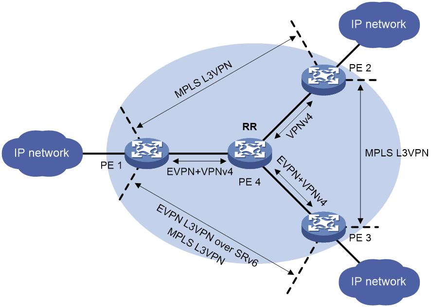
If you specify the preferred keyword in the bestroute encap-type command, BGP prefers the routes with specified encapsulation type (SRv6 or MPLS) when multiple routes have the same Preferred-value attribute value. The subsequent route selection steps are the same as those in the original BGP route select procedure.
If you do not specify the preferred keyword in the bestroute encap-type command, BGP prefers the routes with the specified encapsulation type (SRv6 or MPLS) when multiple routes have the same Preferred-value and LOCAL_PREF attribute values. The subsequent route selection steps are the same as those in the original BGP route select procedure.
For more information about BGP route selection, see BGP overview in Layer 3—IP Routing Configuration Guide.
Restrictions and guidelines
If you use both the bestroute encap-type preferred command and the bestroute nexthop-type preferred command, BGP selects the optimal route in the VPN instance by using the following procedure:
1. Drops the route with an unreachable NEXT_HOP.
2. Selects the route with the highest Preferred-value.
3. Uses the optimal route selection rule configured by the bestroute encap-type command: prefers to use an MPLS-encapsulated or SRv6-encapsulated route.
4. Uses the optimal route selection rule configured by the bestroute nexthop-type command: prefers to use a route whose next hop is an IP address or a tunnel.
5. Selects the route with the highest LOCAL_PREF.
6. Proceeds the subsequent steps in the original BGP route select procedure.
For more information about the bestroute nexthop-type command, see BGP commands in Layer 3—IP Routing Command Reference.
Procedure
1. Enter system view.
system-view
2. Enter BGP instance view.
bgp as-number [ instance instance-name ]
3. Enter BGP-VPN instance view.
ip vpn-instance vpn-instance-name
4. Specify the packet encapsulation type preferred in optimal route selection.
bestroute encap-type { mpls | srv6 } [ preferred ]
By default, BGP does not select optimal routes according to the packet encapsulation type.
Configuring SRv6 TE policy resource usage alarm thresholds
About this task
After you configure this feature, when the number of SRv6 TE policy resources crosses the upper threshold or lower threshold, the device generates log and alarm information. The administrator can then obtain the resource usage status of SRv6 TE policies.
SRv6 TE policy resources include the following:
· Number of valid forwarding paths for all SRv6 TE policies.
· Number of entries of the SRv6Policy type in the SRv6 forwarding table.
· Number of entries of the SRv6PGROUP type in the SRv6 forwarding table.
· Number of entries of the SRv6PSIDList type in the SRv6 forwarding table.
To view SRv6 forwarding table information, use the display segment-routing ipv6 forwarding command.
Restrictions and guidelines
To view resource usage for the current SRv6 TE policy, use the display segment-routing ipv6 te policy statistics command.
Procedure
1. Enter system view.
system-view
2. Enter SRv6 view.
segment-routing ipv6
3. Enter SRv6 TE view.
traffic-engineering
4. Configure the alarm thresholds for resource usage of SRv6 TE policies.
srv6-policy { forwarding-path | policy | policy-group | segment-list } alarm-threshold upper-limit upper-limit-value lower-limit lower-limit-value
By default, the upper and lower alarm thresholds are 80% and 75% for all resources of SRv6 TE policies.
Enabling SRv6 TE policy logging
About this task
This feature enables the device to generate logs for SRv6 TE policy state changes and resource usage anomalies. The administrator can use the logging information to audit SRv6 TE policies. The device delivers logs to its information center. The information center processes the logs according to user-defined output rules (whether to output logs and where to output). For more information about the information center, see the network management and monitoring configuration guide for the device.
Procedure
1. Enter system view.
system-view
2. Enter SRv6 view.
segment-routing ipv6
3. Enter SRv6 TE view.
traffic-engineering
4. Enable SRv6 TE policy logging.
srv6-policy log enable
By default, SRv6 TE policy logging is disabled.
Enabling SNMP notifications for SRv6 TE policies
About this task
This feature enables the device to send SNMP notifications about state changes and resource usage anomalies of SRv6 TE policies. For SNMP notifications to be sent correctly, you must also configure SNMP on the device. For more information about SNMP configuration, see the network management and monitoring configuration guide for the device.
Procedure
1. Enter system view.
system-view
2. Enable SNMP notifications for SRv6 TE policies.
snmp-agent trap enable srv6-policy
By default, SNMP notifications for SRv6 TE policies are disabled.
Configuring traffic forwarding statistics for SRv6 TE policies
About this task
This feature collects statistics on the traffic forwarded by SRv6 TE policies.
Restrictions and guidelines
You can configure traffic forwarding statistics for all SRv6 TE policies globally in SRv6 TE view or for a specific SRv6 TE policy in SRv6 TE policy view. The policy-specific configuration takes precedence over the global configuration. An SRv6 TE policy uses the global configuration only when it has no policy-specific configuration.
Procedure
1. Enter system view.
system-view
2. Enter SRv6 view.
segment-routing ipv6
3. Enter SRv6 TE view.
traffic-engineering
4. Enable traffic forwarding statistics for all SRv6 TE policies.
srv6-policy forwarding statistics [ service-class ] enable
By default, traffic forwarding statistics is disabled for all SRv6 TE policies.
If you specify the service-class keyword, the device collects statistics on the total traffic as well as the traffic of each service class that are forwarded by SRv6 TE policies.
5. (Optional.) Set the traffic forwarding statistics interval for all SRv6 TE policies.
srv6-policy forwarding statistics interval interval
By default, the SRv6 TE policy forwarding statistics interval is 30 seconds.
6. Enter SRv6 TE policy view.
policy policy-name
7. Configure traffic forwarding statistics for the SRv6 TE policy.
forwarding statistics { disable | [ service-class ] enable }
By default, an SRv6 TE policy uses the traffic forwarding statistics configuration in SRv6 TE view.
If you specify the service-class keyword, the device collects statistics on the total traffic as well as the traffic of each service class that are forwarded by the SRv6 TE policy.
Display and maintenance commands for SRv6 TE policies
Execute display commands in any view. Execute reset commands in user view.
|
Task |
Command |
|
Display remote SRv6 SIDs protected by mirror SIDs. |
display bgp [ instance instance-name ] mirror remote-sid [ end-dt4 | end-dt46 | end-dt6 ] [ sid ] |
|
Display BGP peer or peer group information. |
display bgp [ instance instance-name ] peer ipv6 [ sr-policy ] [ ipv6-address prefix-length | { ipv6-address | group-name group-name } log-info | [ ipv6-address ] verbose ] display bgp [ instance instance-name ] peer ipv6 sr-policy [ ipv4-address mask-length | ipv4-address log-info | [ ipv4-address ] verbose ] |
|
Display BGP IPv6 SR policy routing information. |
display bgp [ instance instance-name ] routing-table ipv6 sr-policy [ sr-policy-prefix [ advertise-info ] ] display bgp [ instance instance-name ] routing-table ipv6 sr-policy [ as-path-acl { as-path-acl-number | as-path-acl-name } | as-path-regular-expression regular-expression ] display bgp [ instance instance-name ] routing-table ipv6 sr-policy [ color color-value [ end-point ipv6 ipv6-address ] | end-point ipv6 ipv6-address ] display bgp [ instance instance-name ] routing-table ipv6 sr-policy [ peer { ipv4-address | ipv6-address } { advertised-routes | received-routes } [ sr-policy-prefix [ verbose ] | color color-value [ end-point ipv6 ipv6-address ] | end-point ipv6 ipv6-address | statistics [ color color-value [ end-point ipv6 ipv6-address ] | end-point ipv6 ipv6-address ] ] ] display bgp [ instance instance-name ] routing-table ipv6 sr-policy [ statistics [ color color-value [ end-point ipv6 ipv6-address ] | end-point ipv6 ipv6-address ] ] display bgp [ instance instance-name ] routing-table ipv6 sr-policy peer { ipv4-address | ipv6-address } { accepted-routes | not-accepted-routes } display bgp [ instance instance-name ] routing-table ipv6 sr-policy time-range start-time end-time |
|
Display BGP peer group information. |
display bgp [ instance instance-name ] group ipv6 sr-policy [ group-name group-name ] |
|
Display BGP update group information. |
display bgp [ instance instance-name ] update-group ipv6 sr-policy [ ipv4-address | ipv6-address ] |
|
Display remote SRv6 SIDs protected by mirror SIDs in an EVPN SRv6 network. |
display evpn srv6 mirror remote-sid [ sid | type { end-dt2u | end-dx2 } ] |
|
Display SRv6 TE policy information stored in the PCE |
display pce segment-routing ipv6 policy database [ color color-value endpoint ipv6 ipv6-address | policyname policy-name] [ verbose ] |
|
Display information about the SRv6 TE policy Initiate messages cached in the PCE process. |
display pce segment-routing ipv6 policy initiate-cache |
|
Display BFD information for SRv6 TE policies. |
display segment-routing ipv6 te bfd [ down | policy { { color color-value | end-point ipv6 ipv6-address } * | name policy-name } | up ] |
|
Display SRv6 TE policy database information. |
display segment-routing ipv6 te database [ link | node | prefix | srv6-sid ] |
|
Display SRv6 TE forwarding information. |
display segment-routing ipv6 te forwarding [ binding-sid bsid | policy { name policy-name | { color color-value | end-point ipv6 ipv6-address } * } | xsid xsid ] [ verbose ] |
|
Display SRv6 TE traffic statistics. |
display segment-routing ipv6 te forwarding traffic-statistics |
|
Display SRv6 TE policy information. |
display segment-routing ipv6 te policy [ odn | pce ] [ name policy-name | down | up | { color color-value | end-point ipv6 ip-address } * ] |
|
Display information about the most recent down event for SRv6 TE policies. |
display segment-routing ipv6 te policy last-down-reason [ binding-sid bsid | color color-value endpoint ipv6 ipv6-address | policy-name policy-name ] |
|
Display SRv6 TE policy statistics. |
display segment-routing ipv6 te policy statistics |
|
Display status information about SRv6 TE policies. |
display segment-routing ipv6 te policy status [ policy-name policy-name ] |
|
Display information about SRv6 TE policy groups. |
display segment-routing ipv6 te policy-group [ odn ] [ group-id | { color color-value | end-point ipv6 ipv6-address } * ] [ verbose ] |
|
Display the reason why the specified or all SRv6 TE policy groups went down most recently. |
display segment-routing ipv6 te policy-group last-down-reason [ group-id | endpoint ipv6-address color color-value ] |
|
Display SRv6 TE policy group statistics. |
display segment-routing ipv6 te policy-group statistics |
|
Display SBFD information for SRv6 TE policies. |
display segment-routing ipv6 te sbfd [ down | policy { { color color-value | end-point ipv6 ipv6-address } * | name policy-name } | up ] |
|
Display SRv6 TE policy information for path segments. |
display segment-routing ipv6 te path-segment [ local | reverse ] [ ipv6-address ] |
|
Display SRv6 TE SID list information. |
display segment-routing ipv6 te segment-list [ name seglist-name | id id-value ] |
|
Display information about SRv6 SIDs collected from the LS database. |
display segment-routing ipv6 te source-sid [ end | end-x | sid ] |
|
Display information about IPR policies. |
display segment-routing ipv6 te ipr [ name spr-name ] |
|
Display iFIT measurement information for SRv6 TE policies. |
display segment-routing ipv6 te policy ifit [ name policy-name | down | up | { color color-value | end-point ipv6 ipv6-address } * ] |
|
Display APN ID instance information for SRv6 TE policies. |
display segment-routing ipv6 te policy-group apn-id-ipv6 instance [ name inatnce-name ] |
|
Clear traffic forwarding statistics of SRv6 TE policies. |
reset segment-routing ipv6 te forwarding statistics [ binding-sid binding-sid | color color-value endpoint endpoint-ipv6 | name name-value ] |
SRv6 TE policy configuration examples
Example: Configuring SRv6 TE policy-based forwarding
Network configuration
As shown in Figure 33, perform the following tasks on the devices to implement SRv6 TE policy-based forwarding over a specific path:
· Configure Device A through Device D to run IS-IS to implement Layer 3 connectivity.
· Configure basic SRv6 on Device A through Device D.
· Configure an SRv6 TE policy on Device A to forward user packets along path Device A > Device B > Device C > Device D.
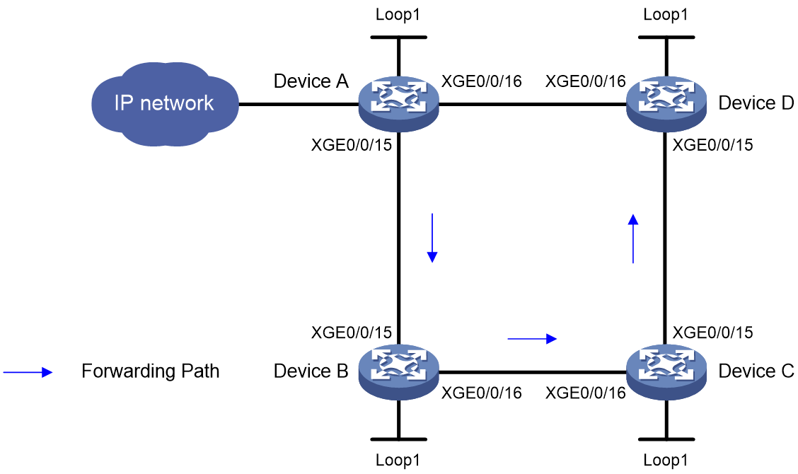
|
Device |
Interface |
IP address |
Device |
Interface |
IP address |
|
Device A |
Loop1 |
1::1/128 |
Device B |
Loop1 |
2::2/128 |
|
|
XGE0/0/15 |
1000::1/64 |
|
XGE0/0/15 |
1000::2/64 |
|
|
XGE0/0/16 |
4000::1/64 |
|
XGE0/0/16 |
2000::2/64 |
|
Device C |
Loop1 |
3::3/128 |
Device D |
Loop1 |
4::4/128 |
|
|
XGE0/0/15 |
3000::3/64 |
|
XGE0/0/15 |
3000::4/64 |
|
|
XGE0/0/16 |
2000::3/64 |
|
XGE0/0/16 |
4000::4/64 |
Procedure
1. Configure IP addresses and masks for interfaces. (Details not shown.)
2. Configure Device A:
# Configure an SRv6 SID list.
<DeviceA> system-view
[DeviceA] segment-routing ipv6
[DeviceA-segment-routing-ipv6] encapsulation source-address 1::1
[DeviceA-segment-routing-ipv6] locator a ipv6-prefix 5000:: 64 static 32
[DeviceA-segment-routing-ipv6-locator-a] opcode 1 end no-flavor
[DeviceA-segment-routing-ipv6-locator-a] quit
[DeviceA-segment-routing-ipv6] traffic-engineering
[DeviceA-srv6-te] srv6-policy locator a
[DeviceA-srv6-te] segment-list s1
[DeviceA-srv6-te-sl-s1] index 10 ipv6 6000::1
[DeviceA-srv6-te-sl-s1] index 20 ipv6 7000::1
[DeviceA-srv6-te-sl-s1] index 30 ipv6 8000::1
[DeviceA-srv6-te-sl-s1] quit
# Create an SRv6 TE policy and set the attributes.
[DeviceA-srv6-te] policy p1
[DeviceA-srv6-te-policy-p1] binding-sid ipv6 5000::2
[DeviceA-srv6-te-policy-p1] color 10 end-point ipv6 4::4
[DeviceA-srv6-te-policy-p1] candidate-paths
[DeviceA-srv6-te-policy-p1-path] preference 10
[DeviceA-srv6-te-policy-p1-path-pref-10] explicit segment-list s1
[DeviceA-srv6-te-policy-p1-path-pref-10] quit
[DeviceA-srv6-te-policy-p1-path] quit
[DeviceA-srv6-te-policy-p1] quit
[DeviceA-srv6-te] quit
[DeviceA-segment-routing-ipv6] quit
# Configure IS-IS and set the IS-IS cost style to wide.
[DeviceA] isis 1
[DeviceA-isis-1] network-entity 00.0000.0000.0001.00
[DeviceA-isis-1] cost-style wide
[DeviceA-isis-1] address-family ipv6 unicast
[DeviceA-isis-1-ipv6] segment-routing ipv6 locator a
[DeviceA-isis-1-ipv6] quit
[DeviceA-isis-1] quit
[DeviceA] interface ten-gigabitethernet 0/0/15
[DeviceA-Ten-GigabitEthernet0/0/15] isis ipv6 enable 1
[DeviceA-Ten-GigabitEthernet0/0/15] quit
[DeviceA] interface ten-gigabitethernet 0/0/16
[DeviceA-Ten-GigabitEthernet0/0/16] isis ipv6 enable 1
[DeviceA-Ten-GigabitEthernet0/0/16] quit
[DeviceA] interface loopback 1
[DeviceA-LoopBack1] isis ipv6 enable 1
[DeviceA-LoopBack1] quit
3. Configure Device B:
# Configure the SRv6 End.SID.
<DeviceB> system-view
[DeviceB] segment-routing ipv6
[DeviceB-segment-routing-ipv6] locator b ipv6-prefix 6000:: 64 static 32
[DeviceB-segment-routing-ipv6-locator-b] opcode 1 end no-flavor
[DeviceB-segment-routing-ipv6-locator-b] quit
[DeviceB-segment-routing-ipv6] quit
# Configure IS-IS and set the IS-IS cost style to wide.
[DeviceB] isis 1
[DeviceB-isis-1] network-entity 00.0000.0000.0002.00
[DeviceB-isis-1] cost-style wide
[DeviceB-isis-1] address-family ipv6 unicast
[DeviceB-isis-1-ipv6] segment-routing ipv6 locator b
[DeviceB-isis-1-ipv6] quit
[DeviceB-isis-1] quit
[DeviceB] interface ten-gigabitethernet 0/0/15
[DeviceB-Ten-GigabitEthernet0/0/15] isis ipv6 enable 1
[DeviceB-Ten-GigabitEthernet0/0/15] quit
[DeviceB] interface ten-gigabitethernet 0/0/16
[DeviceB-Ten-GigabitEthernet0/0/16] isis ipv6 enable 1
[DeviceB-Ten-GigabitEthernet0/0/16] quit
[DeviceB] interface loopback 1
[DeviceB-LoopBack1] isis ipv6 enable 1
[DeviceB-LoopBack1] quit
4. Configure Device C:
# Configure the SRv6 End.SID.
<DeviceC> system-view
[DeviceC] segment-routing ipv6
[DeviceC-segment-routing-ipv6] locator c ipv6-prefix 7000:: 64 static 32
[DeviceC-segment-routing-ipv6-locator-c] opcode 1 end no-flavor
[DeviceC-segment-routing-ipv6-locator-c] quit
[DeviceC-segment-routing-ipv6] quit
# Configure IS-IS and set the IS-IS cost style to wide.
[DeviceC] isis 1
[DeviceC-isis-1] network-entity 00.0000.0000.0003.00
[DeviceC-isis-1] cost-style wide
[DeviceC-isis-1] address-family ipv6 unicast
[DeviceC-isis-1-ipv6] segment-routing ipv6 locator c
[DeviceC-isis-1-ipv6] quit
[DeviceC-isis-1] quit
[DeviceC] interface ten-gigabitethernet 0/0/15
[DeviceC-Ten-GigabitEthernet0/0/15] isis ipv6 enable 1
[DeviceC-Ten-GigabitEthernet0/0/15] quit
[DeviceC] interface ten-gigabitethernet 0/0/16
[DeviceC-Ten-GigabitEthernet0/0/16] isis ipv6 enable 1
[DeviceC-Ten-GigabitEthernet0/0/16] quit
[DeviceC] interface loopback 1
[DeviceC-LoopBack1] isis ipv6 enable 1
[DeviceC-LoopBack1] quit
5. Configure Device D:
# Configure the SRv6 End.SID.
<DeviceD> system-view
[DeviceD] segment-routing ipv6
[DeviceD-segment-routing-ipv6] locator d ipv6-prefix 8000:: 64 static 32
[DeviceD-segment-routing-ipv6-locator-d] opcode 1 end no-flavor
[DeviceD-segment-routing-ipv6-locator-d] quit
[DeviceD-segment-routing-ipv6] quit
# Configure IS-IS and set the IS-IS cost style to wide.
[DeviceD] isis 1
[DeviceD-isis-1] network-entity 00.0000.0000.0004.00
[DeviceD-isis-1] cost-style wide
[DeviceD-isis-1] address-family ipv6 unicast
[DeviceD-isis-1-ipv6] segment-routing ipv6 locator d
[DeviceD-isis-1-ipv6] quit
[DeviceD-isis-1] quit
[DeviceD] interface ten-gigabitethernet 0/0/15
[DeviceD-Ten-GigabitEthernet0/0/15] isis ipv6 enable 1
[DeviceD-Ten-GigabitEthernet0/0/15] quit
[DeviceD] interface ten-gigabitethernet 0/0/16
[DeviceD-Ten-GigabitEthernet0/0/16] isis ipv6 enable 1
[DeviceD-Ten-GigabitEthernet0/0/16] quit
[DeviceD] interface loopback 1
[DeviceD-LoopBack1] isis ipv6 enable 1
[DeviceD-LoopBack1] quit
Verifying the configuration
# Display SRv6 TE policy information on Device A.
[DeviceA] display segment-routing ipv6 te policy
Name/ID: p1/0
Color: 10
Endpoint: 4::4
Name from BGP:
BSID:
Mode: Explicit Type: Type_2 Request state: Succeeded
Current BSID: 5000::2 Explicit BSID: 5000::2 Dynamic BSID: -
Reference counts: 4
Flags: A/BS/NC
Status: Up
AdminStatus: Up
Up time: 2020-04-02 16:08:03
Down time: 2020-04-02 16:03:48
Hot backup: Disabled
Statistics: Disabled
Statistics by service class: Disabled
Path verification: Disabled
Drop-upon-invalid: Disabled
BFD trigger path-down: Disabled
SBFD: Disabled
BFD Echo: Disabled
Forwarding index: 2150629377
Association ID: 1
Service-class: -
Rate-limit: -
PCE delegation: Disabled
PCE delegate report-only: Disabled
Reoptimization: Disabled
Encapsulation mode: -
Candidate paths state: Configured
Candidate paths statistics:
CLI paths: 1 BGP paths: 0 PCEP paths: 0 ODN paths: 0
Candidate paths:
Preference : 10
CPathName:
ProtoOrigin: CLI Discriminator: 10
Instance ID: 0 Node address: 0.0.0.0
Originator: 0, ::
Optimal: Y Flags: V/A
Dynamic: Not configured
PCEP: Not configured
Explicit SID list:
ID: 1 Name: s1
Weight: 1 Forwarding index: 2149580801
State: Up State(-): -
Verification State: -
Path MTU: 1500 Path MTU Reserved: 0
Local BSID: -
Reverse BSID: -
The output shows that the SRv6 TE policy is in up state. The device can use the SRv6 TE policy to forward packets.
# Display SRv6 TE forwarding information on Device A.
[DeviceA] display segment-routing ipv6 te forwarding verbose
Total forwarding entries: 1
Policy name/ID: p1/0
Binding SID: 5000::2
Policy forwarding index: 2150629377
Main path:
Seglist ID: 1
Seglist forwarding index: 2149580801
Weight: 1
Outgoing forwarding index: 2148532225
Interface: XGE0/0/15
Nexthop: FE80::54CB:70FF:FE86:316
Discriminator: 10
Path ID: 0
SID list: {6000::1, 7000::1, 8000::1}
# Display SRv6 forwarding information on Device A.
[DeviceA] display segment-routing ipv6 forwarding
Total SRv6 forwarding entries: 3
Flags: T - Forwarded through a tunnel
N - Forwarded through the outgoing interface to the nexthop IP address
A - Active forwarding information
B - Backup forwarding information
ID FWD-Type Flags Forwarding info
Attri-Val Attri-Val
--------------------------------------------------------------------------------
2148532225 SRv6PSIDList NA XGE0/0/15
FE80::54CB:70FF:FE86:316
{6000::1, 7000::1, 8000::1}
2149580801 SRv6PCPath TA 2148532225
2150629377 SRv6Policy TA 2149580801
p1
Example: Configuring SRv6 TE policy egress protection
Network configuration
As shown in Figure 34, deploy an SRv6 TE policy in both directions between PE 1 and PE 2 to carry the L3VPN service. PE 2 is the egress node of the SRv6 TE policy. To improve the forwarding reliability, configure PE 3 to protect PE 2.
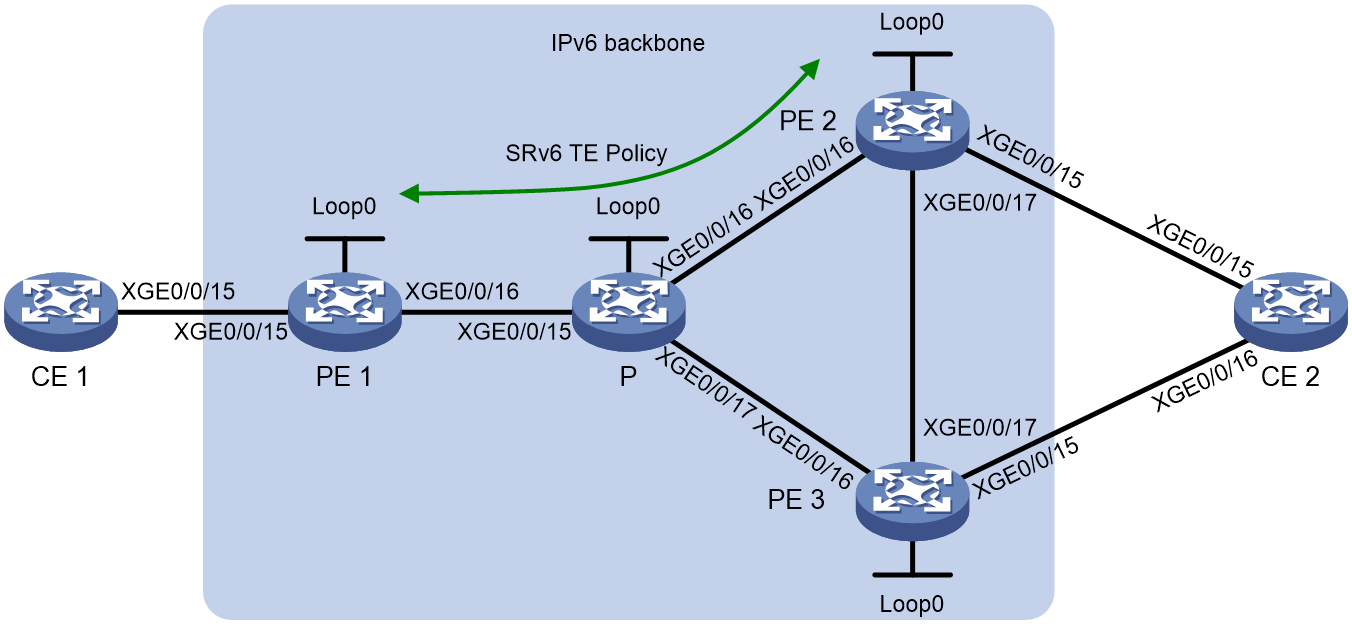
Table 2 Interface and IP address
|
Device |
Interface |
IP Address |
Device |
Interface |
IP Address |
|
CE 1 |
XGE0/0/15 |
10.1.1.2/24 |
PE 2 |
Loop0 |
3::3/128 |
|
PE 1 |
Loop0 |
1::1/128 |
|
XGE0/0/15 |
10.2.1.1/24 |
|
|
XGE0/0/15 |
10.1.1.1/24 |
|
XGE0/0/16 |
2002::1/64 |
|
|
XGE0/0/16 |
2001::1/96 |
|
XGE0/0/17 |
2004::2/96 |
|
P |
Loop0 |
2::2/128 |
PE 3 |
Loop0 |
4::4/128 |
|
|
XGE0/0/15 |
2001::2/96 |
|
XGE0/0/15 |
10.3.1.1/24 |
|
|
XGE0/0/16 |
2002::2/64 |
|
XGE0/0/16 |
2003::1/96 |
|
|
XGE0/0/17 |
2003::2/96 |
|
XGE0/0/17 |
2004::1/96 |
|
|
|
|
CE 2 |
XGE0/0/15 |
10.2.1.2/24 |
|
|
|
|
|
XGE0/0/16 |
10.3.1.2/24 |
Prerequisites
Configure interface addresses as shown in Figure 34Table 2.
Procedure
1. Configure CE 1:
# Establish an EBGP peer relationship with PE 1 and redistribute the VPN routes.
<CE1> system-view
[CE1] bgp 65410
[CE1-bgp-default] peer 10.1.1.1 as-number 100
[CE1-bgp-default] address-family ipv4 unicast
[CE1-bgp-default-ipv4] peer 10.1.1.1 enable
[CE1-bgp-default-ipv4] import-route direct
[CE1-bgp-default-ipv4] quit
[CE1-bgp-default] quit
2. Configure PE 1:
# Configure IPv6 IS-IS for backbone network connectivity.
<PE1> system-view
[PE1] isis 1
[PE1-isis-1] is-level level-1
[PE1-isis-1] cost-style wide
[PE1-isis-1] network-entity 10.1111.1111.1111.00
[PE1-isis-1] address-family ipv6 unicast
[PE1-isis-1-ipv6] quit
[PE1-isis-1] quit
[PE1] interface loopback 0
[PE1-LoopBack0] ipv6 address 1::1 128
[PE1-LoopBack0] isis ipv6 enable 1
[PE1-LoopBack0] quit
[PE1] interface ten-gigabitethernet 0/0/16
[PE1-Ten-GigabitEthernet0/0/16] ipv6 address 2001::1 96
[PE1-Ten-GigabitEthernet0/0/16] isis ipv6 enable 1
[PE1-Ten-GigabitEthernet0/0/16] quit
# Configure a VPN instance and bind it to the CE-facing interface.
[PE1] ip vpn-instance vpn1
[PE1-vpn-instance-vpn1] route-distinguisher 100:1
[PE1-vpn-instance-vpn1] vpn-target 111:1
[PE1-vpn-instance-vpn1] quit
[PE1] interface ten-gigabitethernet 0/0/15
[PE1-Ten-GigabitEthernet0/0/15] ip binding vpn-instance vpn1
[PE1-Ten-GigabitEthernet0/0/15] ip address 10.1.1.1 24
[PE1-Ten-GigabitEthernet0/0/15] quit
# Establish an EBGP peer relationship with the connected CE to redistribute the VPN routes.
[PE1] bgp 100
[PE1-bgp-default] router-id 1.1.1.1
[PE1-bgp-default] ip vpn-instance vpn1
[PE1-bgp-default-vpn1] peer 10.1.1.2 as-number 65410
[PE1-bgp-default-vpn1] address-family ipv4 unicast
[PE1-bgp-default-ipv4-vpn1] peer 10.1.1.2 enable
[PE1-bgp-default-ipv4-vpn1] quit
[PE1-bgp-default-vpn1] quit
# Establish MP-IBGP peer relationships with the peer PEs.
[PE1] bgp 100
[PE1-bgp-default] peer 3::3 as-number 100
[PE1-bgp-default] peer 4::4 as-number 100
[PE1-bgp-default] peer 3::3 connect-interface loopback 0
[PE1-bgp-default] peer 4::4 connect-interface loopback 0
[PE1-bgp-default] address-family vpnv4
[PE1-bgp-default-vpnv4] peer 3::3 enable
[PE1-bgp-default-vpnv4] peer 4::4 enable
[PE1-bgp-default-vpnv4] quit
[PE1-bgp-default] quit
# Configure L3VPN over SRv6 TE policy.
[PE1] segment-routing ipv6
[PE1-segment-routing-ipv6] encapsulation source-address 1::1
[PE1-segment-routing-ipv6] locator aaa ipv6-prefix 1:2::1:0 96 static 8
[PE1-segment-routing-ipv6-locator-aaa] opcode 1 end-dt4 vpn-instance vpn1
[PE1-segment-routing-ipv6-locator-aaa] quit
[PE1-segment-routing-ipv6] quit
[PE1] bgp 100
[PE1-bgp-default] address-family vpnv4
[PE1-bgp-default-vpnv4] peer 3::3 prefix-sid
[PE1-bgp-default-vpnv4] peer 4::4 prefix-sid
[PE1-bgp-default-vpnv4] quit
[PE1-bgp-default] ip vpn-instance vpn1
[PE1-bgp-default-vpn1] address-family ipv4 unicast
[PE1-bgp-default-ipv4-vpn1] segment-routing ipv6 traffic-engineering best-effort
[PE1-bgp-default-ipv4-vpn1] segment-routing ipv6 locator aaa
[PE1-bgp-default-ipv4-vpn1] quit
[PE1-bgp-default-vpn1] quit
[PE1-bgp-default] quit
[PE1] isis 1
[PE1-isis-1] address-family ipv6 unicast
[PE1-isis-1-ipv6] segment-routing ipv6 locator aaa
[PE1-isis-1-ipv6] quit
[PE1-isis-1] quit
# Configure an SRv6 TE policy.
[PE1] segment-routing ipv6
[PE1-segment-routing-ipv6] traffic-engineering
[PE1-srv6-te] srv6-policy locator aaa
[PE1-srv6-te] segment-list s1
[PE1-srv6-te-s1-s1] index 10 ipv6 100:abc:1::1
[PE1-srv6-te-s1-s1] index 20 ipv6 6:5::1:2
[PE1-srv6-te-s1-s1] quit
[PE1-srv6-te] policy p1
[PE1-srv6-te-policy-p1] binding-sid ipv6 1:2::1:2
[PE1-srv6-te-policy-p1] color 10 end-point ipv6 3::3
[PE1-srv6-te-policy-p1] candidate-paths
[PE1-srv6-te-policy-p1-path] preference 10
[PE1-srv6-te-policy-p1-path-pref-10] explicit segment-list s1
[PE1-srv6-te-policy-p1-path-pref-10] quit
[PE1-srv6-te-policy-p1-path] quit
[PE1-srv6-te-policy-p1] quit
[PE1-srv6-te] quit
[PE1-segment-routing-ipv6] quit
3. Configure the P device:
# Configure IPv6 IS-IS for backbone network connectivity.
<P> system-view
[P] isis 1
[P-isis-1] is-level level-1
[P-isis-1] cost-style wide
[P-isis-1] network-entity 10.2222.2222.2222.00
[P-isis-1] address-family ipv6 unicast
[P-isis-1-ipv6] quit
[P-isis-1] quit
[P] interface loopback 0
[P-LoopBack0] ipv6 address 2::2 128
[P-LoopBack0] isis ipv6 enable 1
[P-LoopBack0] quit
[P] interface ten-gigabitethernet 0/0/15
[P-Ten-GigabitEthernet0/0/15] ipv6 address 2001::2 96
[P-Ten-GigabitEthernet0/0/15] isis ipv6 enable 1
[P-Ten-GigabitEthernet0/0/15] quit
[P] interface ten-gigabitethernet 0/0/16
[P-Ten-GigabitEthernet0/0/16] ipv6 address 2002::2 96
[P-Ten-GigabitEthernet0/0/16] isis ipv6 enable 1
[P-Ten-GigabitEthernet0/0/16] quit
[P] interface ten-gigabitethernet 0/0/17
[P-Ten-GigabitEthernet0/0/17] ipv6 address 2003::2 96
[P-Ten-GigabitEthernet0/0/17] isis ipv6 enable 1
[P-Ten-GigabitEthernet0/0/17] quit
# Configure SRv6.
[P] segment-routing ipv6
[P-segment-routing-ipv6] locator p ipv6-prefix 100:abc:1::0 96 static 8
[P-segment-routing-ipv6-locator-p] opcode 1 end no-flavor
[P-segment-routing-ipv6-locator-p] quit
[P-segment-routing-ipv6] quit
[P] isis 1
[P-isis-1] address-family ipv6 unicast
[P-isis-1-ipv6] segment-routing ipv6 locator p
# Configure the FRR backup nexthop information and enable egress protection.
[P-isis-1-ipv6] fast-reroute lfa level-1
[P-isis-1-ipv6] fast-reroute ti-lfa
[P-isis-1-ipv6] fast-reroute mirror enable
[P-isis-1-ipv6] quit
[P-isis-1] quit
4. Configure PE 2:
# Configure IPv6 IS-IS for backbone network connectivity.
<PE2> system-view
[PE2] isis 1
[PE2-isis-1] is-level level-1
[PE2-isis-1] cost-style wide
[PE2-isis-1] network-entity 10.3333.3333.3333.00
[PE2-isis-1] address-family ipv6 unicast
[PE2-isis-1-ipv6] quit
[PE2-isis-1] quit
[PE2] interface loopback 0
[PE2-LoopBack0] ipv6 address 3::3 128
[PE2-LoopBack0] isis ipv6 enable 1
[PE2-LoopBack0] quit
[PE2] interface ten-gigabitethernet 0/0/16
[PE2-Ten-GigabitEthernet0/0/16] ipv6 address 2002::1 96
[PE2-Ten-GigabitEthernet0/0/16] isis ipv6 enable 1
[PE2-Ten-GigabitEthernet0/0/16] quit
[PE2] interface ten-gigabitethernet 0/0/17
[PE2-Ten-GigabitEthernet0/0/17] ipv6 address 2004::2 96
[PE2-Ten-GigabitEthernet0/0/17] isis ipv6 enable 1
[PE2-Ten-GigabitEthernet0/0/17] quit
# Configure a VPN instance and bind it to the CE-facing interface.
[PE2] ip vpn-instance vpn1
[PE2-vpn-instance-vpn1] route-distinguisher 100:1
[PE2-vpn-instance-vpn1] vpn-target 111:1
[PE2-vpn-instance-vpn1] quit
[PE2] interface ten-gigabitethernet 0/0/15
[PE2-Ten-GigabitEthernet0/0/15] ip binding vpn-instance vpn1
[PE2-Ten-GigabitEthernet0/0/15] ip address 10.2.1.1 24
[PE2-Ten-GigabitEthernet0/0/15] quit
# Establish an EBGP peer relationship with the connected CE to redistribute the VPN routes.
[PE2] bgp 100
[PE2-bgp-default] router-id 2.2.2.2
[PE2-bgp-default] ip vpn-instance vpn1
[PE2-bgp-default-vpn1] peer 10.2.1.2 as-number 65420
[PE2-bgp-default-vpn1] address-family ipv4 unicast
[PE2-bgp-default-ipv4-vpn1] peer 10.2.1.2 enable
[PE2-bgp-default-ipv4-vpn1] quit
[PE2-bgp-default-vpn1] quit
# Establish MP-IBGP peer relationships with the peer PEs.
[PE2] bgp 100
[PE2-bgp-default] peer 1::1 as-number 100
[PE2-bgp-default] peer 4::4 as-number 100
[PE2-bgp-default] peer 1::1 connect-interface loopback 0
[PE2-bgp-default] peer 4::4 connect-interface loopback 0
[PE2-bgp-default] address-family vpnv4
[PE2-bgp-default-vpnv4] peer 1::1 enable
[PE2-bgp-default-vpnv4] peer 4::4 enable
[PE2-bgp-default-vpnv4] quit
[PE2-bgp-default] quit
# Configure L3VPN over SRv6 TE policy.
[PE2] segment-routing ipv6
[PE2-segment-routing-ipv6] encapsulation source-address 3::3
[PE2-segment-routing-ipv6] locator bbb ipv6-prefix 6:5::1:0 96 static 8
[PE2-segment-routing-ipv6-locator-bbb] opcode 1 end-dt4 vpn-instance vpn1
[PE2-segment-routing-ipv6-locator-bbb] opcode 2 end no-flavor
[PE2-segment-routing-ipv6-locator-bbb] quit
[PE2-segment-routing-ipv6] quit
[PE2] bgp 100
[PE2-bgp-default] address-family vpnv4
[PE2-bgp-default-vpnv4] peer 1::1 prefix-sid
[PE2-bgp-default-vpnv4] peer 4::4 prefix-sid
[PE2-bgp-default-vpnv4] quit
[PE2-bgp-default] ip vpn-instance vpn1
[PE2-bgp-default-vpn1] address-family ipv4 unicast
[PE2-bgp-default-ipv4-vpn1] segment-routing ipv6 traffic-engineering best-effort
[PE2-bgp-default-ipv4-vpn1] segment-routing ipv6 locator bbb
[PE2-bgp-default-ipv4-vpn1] quit
[PE2-bgp-default-vpn1] quit
[PE2-bgp-default] quit
[PE2] isis 1
[PE2-isis-1] address-family ipv6 unicast
[PE2-isis-1-ipv6] segment-routing ipv6 locator bbb
[PE2-isis-1-ipv6] quit
[PE2-isis-1] quit
5. Configure PE 3:
# Configure IPv6 IS-IS for backbone network connectivity.
<PE3> system-view
[PE3] isis 1
[PE3-isis-1] is-level level-1
[PE3-isis-1] cost-style wide
[PE3-isis-1] network-entity 10.4444.4444.4444.00
[PE3-isis-1] address-family ipv6 unicast
[PE3-isis-1-ipv6] quit
[PE3-isis-1] quit
[PE3] interface loopback 0
[PE3-LoopBack0] ipv6 address 4::4 128
[PE3-LoopBack0] isis ipv6 enable 1
[PE3-LoopBack0] quit
[PE3] interface ten-gigabitethernet 0/0/16
[PE3-Ten-GigabitEthernet0/0/16] ipv6 address 2003::1 96
[PE3-Ten-GigabitEthernet0/0/16] isis ipv6 enable 1
[PE3-Ten-GigabitEthernet0/0/16] quit
[PE3] interface ten-gigabitethernet 0/0/17
[PE3-Ten-GigabitEthernet0/0/17] ipv6 address 2004::1 96
[PE3-Ten-GigabitEthernet0/0/17] isis ipv6 enable 1
[PE3-Ten-GigabitEthernet0/0/17] quit
# Configure a VPN instance and bind it to the CE-facing interface.
[PE3] ip vpn-instance vpn1
[PE3-vpn-instance-vpn1] route-distinguisher 100:1
[PE3-vpn-instance-vpn1] vpn-target 111:1
[PE3-vpn-instance-vpn1] quit
[PE3] interface ten-gigabitethernet 0/0/15
[PE3-Ten-GigabitEthernet0/0/15] ip binding vpn-instance vpn1
[PE3-Ten-GigabitEthernet0/0/15] ip address 10.3.1.1 24
[PE3-Ten-GigabitEthernet0/0/15] quit
# Establish an EBGP peer relationship with the connected CE to redistribute the VPN routes.
[PE3] bgp 100
[PE3-bgp-default] router-id 3.3.3.3
[PE3-bgp-default] ip vpn-instance vpn1
[PE3-bgp-default-vpn1] peer 10.3.1.2 as-number 65420
[PE3-bgp-default-vpn1] address-family ipv4 unicast
[PE3-bgp-default-ipv4-vpn1] peer 10.3.1.2 enable
[PE3-bgp-default-ipv4-vpn1] quit
[PE3-bgp-default-vpn1] quit
# Establish MP-IBGP peer relationships with the peer PEs.
[PE3] bgp 100
[PE3-bgp-default] peer 1::1 as-number 100
[PE3-bgp-default] peer 3::3 as-number 100
[PE3-bgp-default] peer 1::1 connect-interface loopback 0
[PE3-bgp-default] peer 3::3 connect-interface loopback 0
[PE3-bgp-default] address-family vpnv4
[PE3-bgp-default-vpnv4] peer 1::1 enable
[PE3-bgp-default-vpnv4] peer 3::3 enable
[PE3-bgp-default-vpnv4] quit
[PE3-bgp-default] quit
# Configure the source address in the outer IPv6 header of SRv6 VPN packets.
[PE3] segment-routing ipv6
[PE3-segment-routing-ipv6] encapsulation source-address 4::4
# Configure an End.M SID to protect PE 2.
[PE3-segment-routing-ipv6] locator ccc ipv6-prefix 9:7::1:0 96 static 8
[PE3-segment-routing-ipv6-locator-ccc] opcode 1 end-m mirror-locator 6:5::1:0 96
[PE3-segment-routing-ipv6-locator-ccc] quit
[PE3-segment-routing-ipv6] quit
# Recurse the VPN routes to the End.M SID route.
[PE3] bgp 100
[PE3-bgp-default] address-family vpnv4
[PE3-bgp-default-vpnv4] peer 1::1 prefix-sid
[PE3-bgp-default-vpnv4] peer 3::3 prefix-sid
[PE3-bgp-default-vpnv4] quit
[PE3-bgp-default] ip vpn-instance vpn1
[PE3-bgp-default-vpn1] address-family ipv4 unicast
[PE3-bgp-default-ipv4-vpn1] vpn-route cross multipath
[PE3-bgp-default-ipv4-vpn1] segment-routing ipv6 locator ccc
[PE3-bgp-default-ipv4-vpn1] quit
[PE3-bgp-default-vpn1] quit
[PE3-bgp-default] quit
[PE3] isis 1
[PE3-isis-1] address-family ipv6 unicast
[PE3-isis-1-ipv6] segment-routing ipv6 locator ccc
[PE3-isis-1-ipv6] quit
[PE3-isis-1] quit
6. Configure CE 2:
# Establish an EBGP peer relationship with PEs and redistribute the VPN routes.
<CE2> system-view
[CE2] bgp 65420
[CE2-bgp-default] peer 10.2.1.1 as-number 100
[CE2-bgp-default] peer 10.3.1.1 as-number 100
[CE2-bgp-default] address-family ipv4 unicast
[CE2-bgp-default-ipv4] peer 10.2.1.1 enable
[CE2-bgp-default-ipv4] peer 10.3.1.1 enable
[CE2-bgp-default-ipv4] import-route direct
[CE2-bgp-default-ipv4] quit
[CE2-bgp-default] quit
Verifying the configuration
# Display the SRv6 TE policy configuration. The output shows that the SRv6 TE policy is up for traffic forwarding.
[PE1] display segment-routing ipv6 te policy
Name/ID: p1/0
Color: 10
End-point: 3::3
Name from BGP:
BSID:
Mode: Explicit Type: Type_2 Request state: Succeeded
Current BSID: 1:2::1:2 Explicit BSID: 1:2::1:2 Dynamic BSID: -
Reference counts: 4
Flags: A/BS/NC
Status: Up
AdminStatus: Up
Up time: 2020-10-28 09:10:33
Down time: 2020-10-28 09:09:32
Hot backup: Disabled
Statistics: Disabled
Statistics by service class: Disabled
Path verification: Disabled
Drop-upon-invalid: Disabled
BFD trigger path-down: Disabled
SBFD: Disabled
BFD Echo: Disabled
Forwarding index: 2150629377
Association ID: 1
Service-class: -
Rate-limit: -
PCE delegation: Disabled
PCE delegate report-only: Disabled
Reoptimization: Disabled
Encapsulation mode: -
Candidate paths state: Configured
Candidate paths statistics:
CLI paths: 1 BGP paths: 0 PCEP paths: 0 ODN paths: 0
Candidate paths:
Preference : 10
CPathName:
ProtoOrigin: CLI Discriminator: 10
Instance ID: 0 Node address: 0.0.0.0
Originator: 0, ::
Optimal: Y Flags: V/A
Dynamic: Not configured
PCEP: Not configured
Explicit SID list:
ID: 1 Name: s1
Weight: 1 Forwarding index: 2149580801
State: Up State(-): -
Verification State: -
Path MTU: 1500 Path MTU Reserved: 0
Local BSID: -
Reverse BSID: -
# Display SRv6 TE policy forwarding information on PE 1.
[PE1] display segment-routing ipv6 te forwarding verbose
Total forwarding entries: 1
Policy name/ID: p1/0
Binding SID: 1:2::1:2
Forwarding index: 2150629377
Main path:
Seglist ID: 1
Seglist forwarding index: 2149580801
Weight: 1
Outgoing forwarding index: 2148532225
Interface: XGE0/0/16
Nexthop: FE80::988A:B5FF:FED9:316
Discriminator: 10
Path ID: 0
SID list: {100:ABC:1::1, 6:5::1:2}
# Display SRv6 TE policy forwarding path information on PE 1.
[PE1] display segment-routing ipv6 forwarding
Total SRv6 forwarding entries: 3
Flags: T - Forwarded through a tunnel
N - Forwarded through the outgoing interface to the nexthop IP address
A - Active forwarding information
B - Backup forwarding information
ID FWD-Type Flags Forwarding info
Attri-Val Attri-Val
--------------------------------------------------------------------------------
2148532225 SRv6PSIDList NA XGE0/0/16
FE80::988A:B5FF:FED9:316
{100:ABC:1::1, 6:5::1:2}
2149580801 SRv6PCPath TA 2148532225
2150629377 SRv6Policy TA 2149580801
p1
# Display remote SRv6 SIDs protected by End.M SIDs on PE 3.
[PE3] display bgp mirror remote-sid
Remote SID: 6:5::1:1
Remote SID type: End.DT4
Mirror locator: 6:5::1:0/96
Vpn instance name: vpn1
# Display the End.M SID carried in the IS-IS IPv6 route on the P device.
[P] display isis route ipv6 6:5::1:0 96 verbose
Route information for IS-IS(1)
------------------------------
Level-1 IPv6 forwarding table
-----------------------------
IPv6 dest : 6:5::1:0/96
Flag : R/-/- Cost : 10
Admin tag : - Src count : 3
Nexthop : FE80::988A:BDFF:FEB6:417
NexthopFlag: -
Interface : XGE0/0/16
Mirror FRR:
Interface : XGE0/0/17
BkNextHop : FE80::988A:C6FF:FE0D:517
LsIndex : 0x80000001
Backup label stack(top->bottom): {9:7::1:1}
Nib ID : 0x24000006
Flags: D-Direct, R-Added to Rib, L-Advertised in LSPs, U-Up/Down Bit Set
Typically, VPN traffic from CE 1 to CE 2 is forwarded over the CE 1-PE 1-P-PE 2-CE 2 path. When PE 2 fails, the P device switches traffic to the mirror FRR path for the SRv6 TE policy when it detects that the next hop (PE 2) is unreachable.
# Shut down the interface that connects P to PE 2.
[ interface ten-gigabitethernet 0/0/16
[P-Ten-GigabitEthernet0/0/16] shut
[P-Ten-GigabitEthernet0/0/16] quit
# Display the IS-IS IPv6 route information. The output shows that the nexthop interface becomes the backup interface.
[P] display isis route ipv6 6:5::1:0 96 verbose
Route information for IS-IS(1)
------------------------------
Level-1 IPv6 forwarding table
-----------------------------
IPv6 dest : 6:5::1:0/96
Flag : R/-/- Cost : 20
Admin tag : - Src count : 3
Nexthop : FE80::988A:BDFF:FEB6:417
NexthopFlag: -
Interface : XGE0/0/16
Mirror FRR:
Interface : XGE0/0/17
BkNextHop : FE80::988A:C6FF:FE0D:517
LsIndex : 0x80000001
Backup label stack(top->bottom): {9:7::1:1}
Nib ID : 0x24000006
Flags: D-Direct, R-Added to Rib, L-Advertised in LSPs, U-Up/Down Bit Set
# Display SRv6 TE policy information on PE 1. The output shows that the SRv6 TE policy is still up.
[PE1] display segment-routing ipv6 te policy
Name/ID: p1/0
Color: 10
End-point: 3::3
Name from BGP:
BSID:
Mode: Explicit Type: Type_2 Request state: Succeeded
Current BSID: 1:2::1:2 Explicit BSID: 1:2::1:2 Dynamic BSID: -
Reference counts: 4
Flags: A/BS/NC
Status: Up
AdminStatus: Up
Up time: 2020-10-28 09:10:33
Down time: 2020-10-28 09:09:32
Hot backup: Disabled
Statistics: Disabled
Statistics by service class: Disabled
Path verification: Disabled
Drop-upon-invalid: Disabled
BFD trigger path-down: Disabled
SBFD: Disabled
BFD Echo: Disabled
Forwarding index: 2150629377
Association ID: 1
Service-class: -
Rate-limit: -
PCE delegation: Disabled
PCE delegate report-only: Disabled
Reoptimization: Disabled
Encapsulation mode: -
Candidate paths state: Configured
Candidate paths statistics:
CLI paths: 1 BGP paths: 0 PCEP paths: 0 ODN paths: 0
Candidate paths:
Preference : 10
CPathName:
ProtoOrigin: CLI Discriminator: 10
Instance ID: 0 Node address: 0.0.0.0
Originator: 0, ::
Optimal: Y Flags: V/A
Dynamic: Not configured
PCEP: Not configured
Explicit SID list:
ID: 1 Name: s1
Weight: 1 Forwarding index: 2149580801
State: Up State(-): -
Verification State: -
Path MTU: 1500 Path MTU Reserved: 0
Local BSID: -
Reverse BSID: -
Example: Configuring SRv6 TE policy through ODN
Network configuration
As shown in Figure 35, configuring automatic creation of SRv6 TE policies between Device B and Device E by using ODN to forward the traffic between Device A and Device F.
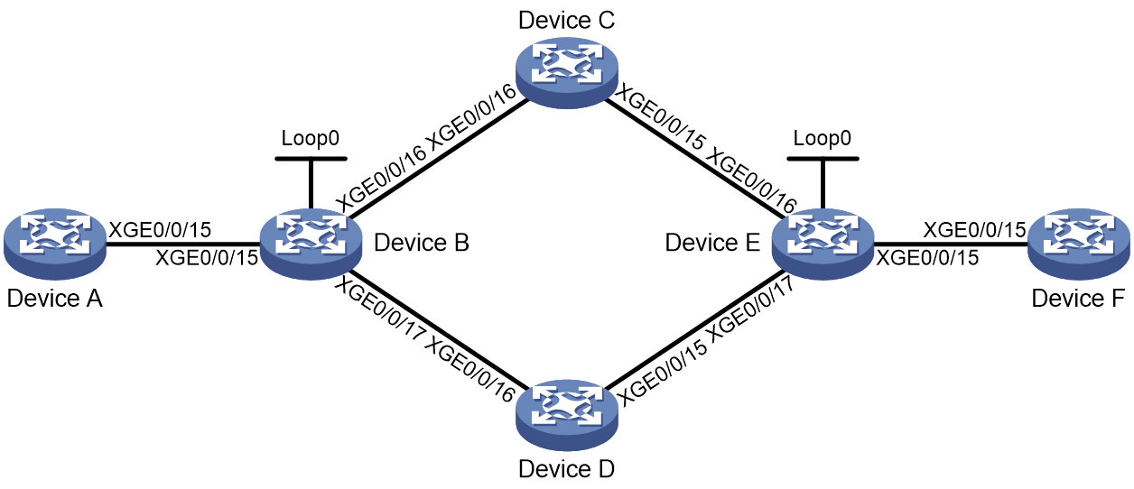
Table 3 Interface and IP address assignment
|
Device |
Interface |
IP Address |
Device |
Interface |
IP Address |
|
Device A |
XGE0/0/15 |
1000::1/64 |
Device F |
XGE0/0/15 |
6000::2/64 |
|
Device B |
Loop0 |
1::1/128 |
Device E |
Loop0 |
3::3/128 |
|
|
XGE0/0/15 |
1000::2/64 |
|
XGE0/0/15 |
6000::1/64 |
|
|
XGE0/0/16 |
2000::1/64 |
|
XGE0/0/16 |
4000::/64 |
|
|
XGE0/0/17 |
3000::1/64 |
|
XGE0/0/17 |
5000::1/64 |
|
Device C |
XGE0/0/15 |
4000::2/64 |
Device D |
XGE0/0/15 |
5000::2/64 |
|
|
XGE0/0/16 |
2002::2/64 |
|
XGE0/0/16 |
3000::2/64 |
Prerequisites
Configure interface addresses as shown in Figure 35Table 3.
Proedure
1. Configure Device A:
# Configure IS-IS and set the IS-IS cost style to wide.
<DeviceA> system-view
[DeviceA] isis 1
[DeviceA-isis-1] cost-style wide
[DeviceA-isis-1] network-entity 00.0000.0000.0001.00
[DeviceA-isis-1] address-family ipv6 unicast
[DeviceA-isis-1-ipv6] quit
[DeviceA-isis-1] quit
[DeviceA] interface ten-gigabitethernet 0/0/15
[DeviceA-Ten-GigabitEthernet0/0/15] isis ipv6 enable 1
[DeviceA-Ten-GigabitEthernet0/0/15] quit
2. Configure Device B:
# Configure IS-IS and set the IS-IS cost style to wide.
<DeviceB> system-view
[DeviceB] isis 1
[DeviceB-isis-1] cost-style wide
[DeviceB-isis-1] network-entity 00.0000.0000.0002.00
[DeviceB-isis-1] address-family ipv6 unicast
[DeviceB-isis-1-ipv6] quit
[DeviceB-isis-1] quit
[DeviceB] interface ten-gigabitethernet 0/0/15
[DeviceB-Ten-GigabitEthernet0/0/15] isis ipv6 enable 1
[DeviceB-Ten-GigabitEthernet0/0/15] quit
[DeviceB] interface ten-gigabitethernet 0/0/16
[DeviceB-Ten-GigabitEthernet0/0/16] isis ipv6 enable 1
[DeviceB-Ten-GigabitEthernet0/0/16] quit
[DeviceB] interface ten-gigabitethernet 0/0/17
[DeviceB-Ten-GigabitEthernet0/0/17] isis ipv6 enable 1
[DeviceB-Ten-GigabitEthernet0/0/17] quit
[DeviceB] interface loopback 0
[DeviceB-LoopBack0] isis ipv6 enable 1
[DeviceB-LoopBack0] quit
# Establish a BGP peer relationship with Device E.
[DeviceB] bgp 100
[DeviceB-bgp-default] router-id 1.1.1.1
[DeviceB-bgp-default] peer 3::3 as-number 100
[DeviceB-bgp-default] peer 3::3 connect-interface loopback 0
[DeviceB-bgp-default] address-family ipv6
[DeviceB-bgp-default-ipv6] peer 3::3 enable
[DeviceB-bgp-default-ipv6] quit
[DeviceB-bgp-default] address-family ipv6 sr-policy
[DeviceB-bgp-default-srpolicy-ipv6] peer 3::3 enable
[DeviceB-bgp-default-srpolicy-ipv6] quit
[DeviceB-bgp-default] quit
# Configure an SRv6 locator.
[DeviceB] segment-routing ipv6
[DeviceB-segment-routing-ipv6] encapsulation source-address 1::1
[DeviceB-segment-routing-ipv6] locator b ipv6-prefix 20:1:: 96 static 24
[DeviceB-segment-routing-ipv6-locator-b] opcode 1 end no-flavor
[DeviceB-segment-routing-ipv6-locator-b] quit
[DeviceB-segment-routing-ipv6] quit
# Configure ODN to create an SRv6 TE policy automatically.
[DeviceB] segment-routing ipv6
[DeviceB-segment-routing-ipv6] traffic-engineering
[DeviceB-srv6-te] srv6-policy locator b
[DeviceB-srv6-te] on-demand color 1
# Enable path computation using PCE.
[DeviceB-srv6-te-odn-1] dynamic
[DeviceB-srv6-te-odn-1-dynamic] pcep
[DeviceB-srv6-te-odn-1] quit
[DeviceB-srv6-te] quit
[DeviceB-segment-routing-ipv6] quit
[DeviceB] isis 1
[DeviceB-isis-1] address-family ipv6 unicast
[DeviceB-isis-1-ipv6] segment-routing ipv6 locator b
[DeviceB-isis-1-ipv6] quit
[DeviceB-isis-1] quit
3. Configure Device C:
# Configure IS-IS and set the IS-IS cost style to wide.
<DeviceC> system-view
[DeviceC] isis 1
[DeviceC-isis-1] cost-style wide
[DeviceC-isis-1] network-entity 00.0000.0000.0003.00
[DeviceC-isis-1] address-family ipv6 unicast
[DeviceC-isis-1-ipv6] quit
[DeviceC-isis-1] quit
[DeviceC] interface ten-gigabitethernet 0/0/15
[DeviceC-Ten-GigabitEthernet0/0/15] isis ipv6 enable 1
[DeviceC-Ten-GigabitEthernet0/0/15] quit
[DeviceC] interface ten-gigabitethernet 0/0/16
[DeviceC-Ten-GigabitEthernet0/0/16] isis ipv6 enable 1
[DeviceC-Ten-GigabitEthernet0/0/16] quit
[DeviceC] interface loopback 0
[DeviceC-LoopBack1] isis ipv6 enable 1
[DeviceC-LoopBack1] quit
4. Configure Device D:
# Configure IS-IS and set the IS-IS cost style to wide.
<DeviceD> system-view
[DeviceD] isis 1
[DeviceD-isis-1] cost-style wide
[DeviceD-isis-1] network-entity 00.0000.0000.0004.00
[DeviceD-isis-1] address-family ipv6 unicast
[DeviceD-isis-1-ipv6] quit
[DeviceD-isis-1] quit
[DeviceD] interface ten-gigabitethernet 0/0/15
[DeviceD-Ten-GigabitEthernet0/0/15] isis ipv6 enable 1
[DeviceD-Ten-GigabitEthernet0/0/15] quit
[DeviceD] interface ten-gigabitethernet 0/0/16
[DeviceD-Ten-GigabitEthernet0/0/16] isis ipv6 enable 1
[DeviceD-Ten-GigabitEthernet0/0/16] quit
[DeviceD] interface loopback 0
[DeviceD-LoopBack0] isis ipv6 enable 1
[DeviceD-LoopBack0] quit
5. Configure Device E:
# Configure IS-IS and set the IS-IS cost style to wide.
<DeviceE> system-view
[DeviceE] isis 1
[DeviceE-isis-1] cost-style wide
[DeviceE-isis-1] network-entity 00.0000.0000.0005.00
[DeviceE-isis-1] address-family ipv6 unicast
[DeviceE-isis-1-ipv6] quit
[DeviceE-isis-1] quit
[DeviceE] interface ten-gigabitethernet 0/0/15
[DeviceE-Ten-GigabitEthernet0/0/15] isis ipv6 enable 1
[DeviceE-Ten-GigabitEthernet0/0/15] quit
[DeviceE] interface ten-gigabitethernet 0/0/16
[DeviceE-Ten-GigabitEthernet0/0/16] isis ipv6 enable 1
[DeviceE-Ten-GigabitEthernet0/0/16] quit
[DeviceE] interface ten-gigabitethernet 0/0/17
[DeviceE-Ten-GigabitEthernet0/0/17] isis ipv6 enable 1
[DeviceE-Ten-GigabitEthernet0/0/17] quit
[DeviceE] interface loopback 0
[DeviceE-LoopBack0] isis ipv6 enable 1
[DeviceE-LoopBack0] quit
[DeviceE] interface loopback 1
[DeviceE-LoopBack1] ipv6 address 2::2 128
[DeviceE-LoopBack1] quit
# Establish a BGP peer relationship with Device B.
[DeviceE] bgp 100
[DeviceE-bgp-default] router-id 3.3.3.3
[DeviceE-bgp-default] peer 1::1 as-number 100
[DeviceE-bgp-default] peer 1::1 connect-interface loopback 0
[DeviceE-bgp-default] address-family ipv6
[DeviceE-bgp-default-ipv6] peer 1::1 enable
[DeviceE-bgp-default-ipv6] network 2::2 128
[DeviceE-bgp-default-ipv6] quit
[DeviceE-bgp-default] address-family ipv6 sr-policy
[DeviceE-bgp-default-srpolicy-ipv6] peer 1::1 enable
[DeviceE-bgp-default-srpolicy-ipv6] quit
[DeviceE-bgp-default] quit
# Configure a route policy to add a color attribute to the export routes.
[DeviceE] route-policy 1 permit node 10
[DeviceE-route-policy-1-10] apply extcommunity color 01:1
[DeviceE-route-policy-1-10] quit
[DeviceE] bgp 100
[DeviceE-bgp-default] address-family ipv6 unicast
[DeviceE-bgp-default-ipv6] peer 1::1 route-policy 1 export
[DeviceE-bgp-default-ipv6] peer 1::1 advertise-community
[DeviceE-bgp-default-ipv6] peer 1::1 advertise-ext-community
[DeviceE-bgp-default-ipv6] quit
[DeviceE-bgp-default] quit
6. Configure Device F:
# Configure IS-IS and set the IS-IS cost style to wide.
<DeviceF> system-view
[DeviceF] isis 1
[DeviceF-isis-1] network-entity 00.0000.0000.0006.00
[DeviceF-isis-1] cost-style wide
[DeviceF-isis-1] address-family ipv6 unicast
[DeviceF-isis-1-ipv6] quit
[DeviceF-isis-1] quit
[DeviceF] interface ten-gigabitethernet 0/0/15
[DeviceF-Ten-GigabitEthernet0/0/15] isis ipv6 enable 1
[DeviceF-Ten-GigabitEthernet0/0/15] quit
Verifying the configuration
# Display information about the ODN-created SRv6 TE policy on Device B.
[DeviceB] display segment-routing ipv6 te policy
Name/ID: sr-1-3::3/0
Color: 1
End-point: 3::3
Name from BGP: sr-1-3::3
Name from PCE:
BSID:
Mode: Dynamic Type: Type_2 Request state: Succeeded
Current BSID: 20:1::100:0 Explicit BSID: - Dynamic BSID: 20:1::100:0
Reference counts: 4
Flags: A/BS/NC
Status: Up
AdminStatus: Up
Up time: 2020-12-01 15:58:12
Down time: 2020-12-01 15:58:12
Hot backup: Disabled
Statistics: Disabled
Statistics by service class: Disabled
Path verification: Disabled
Drop-upon-invalid: Disabled
BFD trigger path-down: Disabled
SBFD: Disabled
BFD Echo: Disabled
Forwarding index: 2150629377
Association ID: 1
Service-class: -
Rate-limit: -
PCE delegation: Disabled
PCE delegate report-only: Disabled
Reoptimization: Disabled
Encapsulation mode: -
Candidate paths state: Not configured
Candidate paths statistics:
CLI paths: 0 BGP paths: 0 PCEP paths: 0 ODN paths: 2
Candidate paths:
Preference : 100
CPathName: sr-1-3::3
ProtoOrigin: BGP Discriminator: 100
Instance ID: 0 Node address: 0.0.0.0
Originator: 0, ::
Optimal: N Flags: None
Dynamic: Configured
PCEP: Configured
Candidate paths:
Preference : 200
CPathName: sr-1-3::3
ProtoOrigin: BGP Discriminator: 200
Instance ID: 0 Node address: 0.0.0.0
Originator: 0, ::
Optimal: N Flags: BN
Dynamic: Not configured
PCEP: Not configured
# Display the forwarding path information of the SRv6 TE policy.
[DeviceB] display segment-routing ipv6 forwarding
Total SRv6 forwarding entries: 1
Flags: T - Forwarded through a tunnel
N - Forwarded through the outgoing interface to the nexthop IP address
A - Active forwarding information
B - Backup forwarding information
ID FWD-Type Flags Forwarding info
--------------------------------------------------------------------------------
2150630377 SRv6Policy TA 2149581800
# Display the forwarding information of the SRv6 TE policy.
[DeviceB] display segment-routing ipv6 te forwarding verbose
Total forwarding entries: 1
Policy name/ID: sr-1-3::3/1001
Binding SID: 20:1::100:0
Forwarding index: 2150630377
Main path:
Seglist ID: 4369
Seglist forwarding index: 2149581800
Weight: 1
Outgoing forwarding index: 2148533223
Interface: GE1/0/3
Nexthop: FE80::7AAA:12FF:FED8:309
Discriminator: 100
Path ID: 0
SID list: {6:5::1:5}
# Display BGP route information for the SRv6 TE policy.
[DeviceB] display bgp routing-table ipv6 3::3 128
BGP local router ID: 1.1.1.1
Local AS number: 100
Paths: 1 available, 1 best
BGP routing table information of 3::3/128:
From : 3::3 (2.2.2.2)
Rely nexthop : FE80::7AAA:12FF:FED8:309
Original nexthop: 3::3
Out interface : GigabitEthernet1/0/3
Route age : 00h17m00s
OutLabel : NULL
Ext-Community : <CO-Flag:Color(01:1)>
RxPathID : 0x0
TxPathID : 0xffffffff
AS-path : (null)
Origin : incomplete
Attribute value : MED 0, localpref 100, pref-val 0
State : valid, internal, not preferred for igp-cost, not ECMP for igp-cost
IP precedence : N/A
QoS local ID : N/A
Traffic index : N/A
Tunnel policy : N/A
Rely tunnel IDs : 2150630377
Example: Configuring SRv6 TE policy-based forwarding with IPR
Network configuration
As shown in Figure 36:
· AS 100 is an IPv6 network and the private networks are IPv4 networks.
· PE 1, P 1, P 2, P 3, and PE 2 belong to one AS, and they run IS-IS for IPv6 network connectivity.
· An SRv6 TE policy group is created between PE 1 and PE 2. The SRv6 TE policy group contains three SRv6 TE policies with different forwarding paths to carry IPv4 L3VPN service traffic.
· Routing policies are configured on PE 1 and PE 2 to match color attribute values in VPNv4 routes and steer VPN traffic to the SRv6 TE policy group between PE 1 and PE 2.
· An IPR policy is configured for dynamic forwarding path selection.
The SRv6 TE policies are configured as follows:
· SRv6 TE policy A has one candidate path. The forwarding path represented by the SID list is PE 1 > P 1 > PE 2.
· SRv6 TE policy B has one candidate path. The forwarding path represented by the SID list is PE 1 > P 2 > PE 2.
· SRv6 TE policy C has one candidate path. The forwarding path represented by the SID list is PE 1 > P 3 > PE 2.
The IPR policy contains the following settings:
· The packet loss rate threshold is 5‰, delay threshold is 100 ms, jitter threshold is 10 ms, and CMI threshold is 110.
· The path selection priority is 1 for SRv6 TE policy A, 2 for SRv6 TE policy B, and 3 for SRv6 TE policy C.
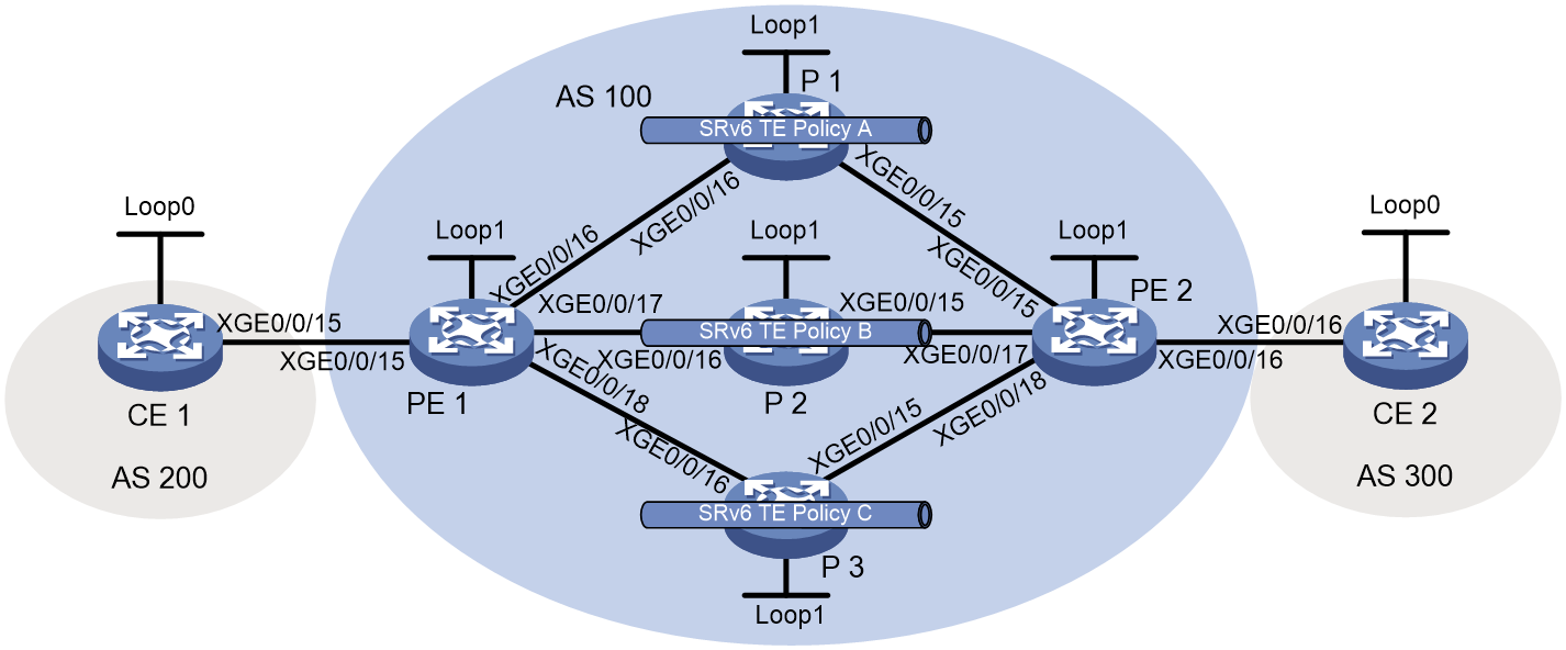
|
Device |
Interface |
IP address |
Device |
Interface |
IP address |
|
CE 1 |
XGE0/0/15 |
10.1.1.1/24 |
CE 2 |
XGE0/0/16 |
20.1.1.1/24 |
|
|
Loop0 |
11.11.11.11/32 |
|
Loop0 |
22.22.22.22/32 |
|
PE 1 |
Loop1 |
1::1/128 |
P 1 |
Loop1 |
2::2/128 |
|
|
XGE0/0/15 |
10.1.1.2/24 |
|
XGE0/0/15 |
5001::2/96 |
|
|
XGE0/0/16 |
2001::1/96 |
|
XGE0/0/16 |
2001::2/96 |
|
|
XGE0/0/17 |
3001::1/96 |
P 2 |
Loop1 |
4::4/128 |
|
|
XGE0/0/18 |
4001::1/96 |
|
XGE0/0/15 |
6001::2/96 |
|
PE 2 |
Loop1 |
3::3/128 |
|
XGE0/0/16 |
3001::2/96 |
|
|
XGE0/0/15 |
5001::1/96 |
P 3 |
Loop1 |
5::5/128 |
|
|
XGE0/0/16 |
20.1.1.2/24 |
|
XGE0/0/15 |
7001::2/96 |
|
|
XGE0/0/17 |
6001::1/96 |
|
XGE0/0/16 |
4001::2/96 |
|
|
XGE0/0/18 |
7001::1/96 |
|
|
|
Procedure
1. Configure IPv6 addresses and prefix lengths for interfaces as shown in Figure 36. (Details not shown.)
2. Configure CE 1:
# Configure EBGP to advertise private routes to PE 1.
<CE1> system-view
[CE1] bgp 200
[CE1-bgp-default] router-id 11.11.11.11
[CE1-bgp-default] peer 10.1.1.2 as-number 100
[CE1-bgp-default] address-family ipv4 unicast
[CE1-bgp-default-ipv4] peer 10.1.1.2 enable
[CE1-bgp-default-ipv4] import-route direct
[CE1-bgp-default-ipv4] quit
[CE1-bgp-default] quit
3. Configure CE 2:
# Configure EBGP to advertise private routes to PE 2.
[CE2] bgp 300
[CE2-bgp-default] router-id 22.22.22.22
[CE2-bgp-default] peer 20.1.1.2 as-number 100
[CE2-bgp-default] address-family ipv4 unicast
[CE2-bgp-default-ipv4] peer 20.1.1.2 enable
[CE2-bgp-default-ipv4] import-route direct
[CE2-bgp-default-ipv4] quit
[CE2-bgp-default] quit
4. Configure PE 1:
# Configure IPv6 IS-IS for backbone network connectivity.
<PE1> system-view
[PE1] isis 1
[PE1-isis-1] cost-style wide
[PE1-isis-1] network-entity 00.0000.0000.0001.00
[PE1-isis-1] address-family ipv6 unicast
[PE1-isis-1-ipv6] quit
[PE1-isis-1] quit
[PE1] interface loopback 1
[PE1-LoopBack1] isis ipv6 enable 1
[PE1-LoopBack1] quit
[PE1] interface ten-gigabitethernet 0/0/16
[PE1-Ten-GigabitEthernet0/0/16] isis ipv6 enable 1
[PE1-Ten-GigabitEthernet0/0/16] quit
[PE1] interface ten-gigabitethernet 0/0/17
[PE1-Ten-GigabitEthernet0/0/17] isis ipv6 enable 1
[PE1-Ten-GigabitEthernet0/0/17] quit
[PE1] interface ten-gigabitethernet 0/0/18
[PE1-Ten-GigabitEthernet0/0/18] isis ipv6 enable 1
[PE1-Ten-GigabitEthernet0/0/18] quit
# Configure a VPN instance to attach CE 1 to PE 1.
[PE1] ip vpn-instance vpn1
[PE1-vpn-instance-vpn1] route-distinguisher 100:1
[PE1-vpn-instance-vpn1] vpn-target 100:1
[PE1-vpn-instance-vpn1] quit
[PE1] interface ten-gigabitethernet 0/0/15
[PE1-Ten-GigabitEthernet0/0/15] ip binding vpn-instance vpn1
[PE1-Ten-GigabitEthernet0/0/15] ip address 10.1.1.2 24
[PE1-Ten-GigabitEthernet0/0/15] quit
# Establish an EBGP peer relationship with CE 1 and import VPN routes.
[PE1] bgp 100
[PE1-bgp-default] router-id 1.1.1.1
[PE1-bgp-default] ip vpn-instance vpn1
[PE1-bgp-default-vpn1] peer 10.1.1.1 as-number 200
[PE1-bgp-default-vpn1] address-family ipv4 unicast
[PE1-bgp-default-ipv4-vpn1] peer 10.1.1.1 enable
[PE1-bgp-default-ipv4-vpn1] import-route direct
[PE1-bgp-default-ipv4-vpn1] quit
[PE1-bgp-default-vpn1] quit
# Establish an MP-IBGP peer relationship with PE 2.
[PE1-bgp-default] peer 3::3 as-number 100
[PE1-bgp-default] peer 3::3 connect-interface loopback 1
[PE1-bgp-default] address-family vpnv4
[PE1-bgp-default-vpnv4] peer 3::3 enable
[PE1-bgp-default-vpnv4] quit
[PE1-bgp-default] quit
# Recurse VPN routes between PE 1 and PE 2 to the SRv6 TE policy group.
[PE1] segment-routing ipv6
[PE1-segment-routing-ipv6] encapsulation source-address 1::1
[PE1-segment-routing-ipv6] locator abc ipv6-prefix 100:1:: 64 static 16
[PE1-segment-routing-ipv6-locator-abc] opcode 1 end no-flavor
[PE1-segment-routing-ipv6-locator-abc] quit
[PE1-segment-routing-ipv6] quit
[PE1] isis 1
[PE1-isis-1] address-family ipv6 unicast
[PE1-isis-1-ipv6] segment-routing ipv6 locator abc
[PE1-isis-1-ipv6] quit
[PE1-isis-1] quit
[PE1] bgp 100
[PE1-bgp-default] address-family vpnv4
[PE1-bgp-default-vpnv4] peer 3::3 prefix-sid
[PE1-bgp-default-vpnv4] quit
[PE1-bgp-default] ip vpn-instance vpn1
[PE1-bgp-default-vpn1] address-family ipv4 unicast
[PE1-bgp-default-ipv4-vpn1] segment-routing ipv6 locator abc
[PE1-bgp-default-ipv4-vpn1] segment-routing ipv6 traffic-engineering
[PE1-bgp-default-ipv4-vpn1] quit
[PE1-bgp-default-vpn1] quit
[PE1-bgp-default] quit
# Configure SRv6 TE policy A.
[PE1] segment-routing ipv6
[PE1-segment-routing-ipv6] traffic-engineering
[PE1-srv6-te] srv6-policy locator abc
[PE1-srv6-te] segment-list s1
[PE1-srv6-te-sl-s1] index 10 ipv6 200:1::1
[PE1-srv6-te-sl-s1] index 20 ipv6 300:1::1
[PE1-srv6-te-sl-s1] quit
[PE1-srv6-te] policy A
[PE1-srv6-te-policy-A] color 10 end-point ipv6 3::3
[PE1-srv6-te-policy-A] candidate-paths
[PE1-srv6-te-policy-A-path] preference 10
[PE1-srv6-te-policy-A-path-pref-10] explicit segment-list s1
[PE1-srv6-te-policy-A-path-pref-10] quit
[PE1-srv6-te-policy-A-path] quit
[PE1-srv6-te-policy-A] quit
[PE1-srv6-te] quit
[PE1-segment-routing-ipv6] quit
# Configure SRv6 TE policy B.
[PE1] segment-routing ipv6
[PE1-segment-routing-ipv6] traffic-engineering
[PE1-srv6-te] srv6-policy locator abc
[PE1-srv6-te] segment-list s2
[PE1-srv6-te-sl-s1] index 10 ipv6 400:1::1
[PE1-srv6-te-sl-s1] index 20 ipv6 300:1::1
[PE1-srv6-te-sl-s1] quit
[PE1-srv6-te] policy B
[PE1-srv6-te-policy-B] color 20 end-point ipv6 3::3
[PE1-srv6-te-policy-B] candidate-paths
[PE1-srv6-te-policy-B-path] preference 10
[PE1-srv6-te-policy-B-path-pref-10] explicit segment-list s2
[PE1-srv6-te-policy-B-path-pref-10] quit
[PE1-srv6-te-policy-B-path] quit
[PE1-srv6-te-policy-B] quit
[PE1-srv6-te] quit
[PE1-segment-routing-ipv6] quit
# Configure SRv6 TE policy C.
[PE1] segment-routing ipv6
[PE1-segment-routing-ipv6] traffic-engineering
[PE1-srv6-te] srv6-policy locator abc
[PE1-srv6-te] segment-list s3
[PE1-srv6-te-sl-s1] index 10 ipv6 500:1::1
[PE1-srv6-te-sl-s1] index 20 ipv6 300:1::1
[PE1-srv6-te-sl-s1] quit
[PE1-srv6-te] policy C
[PE1-srv6-te-policy-C] color 30 end-point ipv6 3::3
[PE1-srv6-te-policy-C] candidate-paths
[PE1-srv6-te-policy-C-path] preference 10
[PE1-srv6-te-policy-C-path-pref-10] explicit segment-list s3
[PE1-srv6-te-policy-C-path-pref-10] quit
[PE1-srv6-te-policy-C-path] quit
[PE1-srv6-te-policy-C] quit
[PE1-srv6-te] quit
[PE1-segment-routing-ipv6] quit
# Enable iFIT, configure the iFIT device ID, set the iFIT operating mode to analyzer, and globally enable iFIT packet loss measurement and iFIT delay and jitter measurement for SRv6 TE policies.
[PE1] ifit enable
[PE1-ifit] device-id 100
[PE1-ifit] work-mode analyzer
[PE1-ifit-analyzer] service-type srv6-segment-list
[PE1-ifit-analyzer] quit
[PE1-ifit] quit
[PE1] segment-routing ipv6
[PE1-segment-routing-ipv6] traffic-engineering
[PE1-srv6-te] srv6-policy ifit loss-measure enable
[PE1-srv6-te] srv6-policy ifit delay-measure enable
[PE1-srv6-te] srv6-policy ifit interval 10
# Globally enable SBFD for SRv6 TE policies.
[PE1] sbfd source-ipv6 1::1
[PE1] bfd multi-hop detect-multiplier 5
[PE1] bfd multi-hop min-transmit-interval 50
[PE1] segment-routing ipv6
[PE1-segment-routing-ipv6] traffic-engineering
[PE1-srv6-te] srv6-policy sbfd remote 1000001
[PE1-srv6-te] quit
[PE1-segment-routing-ipv6] quit
# Configure IPR policy ipr1 and configure parameters in the IPR policy.
[PE1] segment-routing ipv6
[PE1-segment-routing-ipv6] traffic-engineering
[PE1-srv6-te] intelligent-policy-route
[PE1-srv6-te-ipr] refresh-period 30
[PE1-srv6-te-ipr] ipr-policy ipr1
[PE1-srv6-ipr-policy-ipr1] delay threshold 100
[PE1-srv6-ipr-policy-ipr1] jitter threshold 10
[PE1-srv6-ipr-policy-ipr1] loss threshold 5
[PE1-srv6-ipr-policy-ipr1] cmi threshold 110
[PE1-srv6-ipr-policy-ipr1] srv6-policy color 10 priority 1
[PE1-srv6-ipr-policy-ipr1] srv6-policy color 20 priority 2
[PE1-srv6-ipr-policy-ipr1] srv6-policy color 30 priority 3
[PE1-srv6-ipr-policy-ipr1] quit
[PE1-srv6-te-ipr] quit
[PE1-srv6-te] quit
[PE1-segment-routing-ipv6] quit
# In the inbound direction of Ten-GigabitEthernet 0/0/15, mark the private network service traffic from CE 1 to CE 2, with a source address of 11.11.11.11/32 and a destination address of 22.22.22.22/32, with TE class ID 10.
[PE1] acl advanced 3000
[PE1-acl-ipv4-adv-3000] rule 10 permit ip source 11.11.11.11 0 destination 22.22.22.22 0
[PE1-acl-ipv4-adv-3000] quit
[PE1] traffic classifier aaa
[PE1-classifier-aaa] if-match acl 3000
[PE1-classifier-aaa] quit
[PE1] traffic behavior aaa
[PE1-behavior-aaa] remark te-class 10
[PE1-behavior-aaa] quit
[PE1] qos policy aaa
[PE1-qospolicy-aaa] classifier aaa behavior aaa
[PE1-qospolicy-aaa] quit
[PE1] interface ten-gigabitethernet 0/0/15
[PE1-Ten-GigabitEthernet0/0/15] qos apply policy aaa inbound
[PE1-Ten-GigabitEthernet0/0/15] quit
# Configure SRv6 TE policy group 10. In the SRv6 TE policy group, use TE class ID-based traffic steering, configure a mapping between TE class ID 10 and IPR policy ipr1, and specify the SRv6 BE mode in the default forwarding policy.
[PE1] segment-routing ipv6
[PE1-segment-routing-ipv6] traffic-engineering
[PE1-srv6-te] policy-group 10
[PE1-srv6-te-policy-group-10] end-point ipv6 3::3
[PE1-srv6-te-policy-group-10] group-color 100
[PE1-srv6-te-policy-group-10] forward-type te-class
[PE1-srv6-te-policy-group-10] index 1 te-class 10 match ipr-policy ipr1
[PE1-srv6-te-policy-group-10] default match best-effort
# Configure a routing policy and tunnel policy to steer VPN service traffic to the SRv6 TE policy group through the routing policy and preferentially select the SRv6 TE policy group for traffic forwarding.
[PE1] route-policy a permit node 10
[PE1-route-policy-a-10] apply extcommunity color 00:100
[PE1-route-policy-a-10] quit
[PE1] bgp 100
[PE1-bgp-default] address-family vpnv4
[PE1-bgp-default-vpnv4] peer 3::3 route-policy a import
[PE1-bgp-default-vpnv4] quit
[PE1-bgp-default] quit
[PE1] tunnel-policy a
[PE1-tunnel-policy-a] select-seq srv6-policy-group load-balance-number 1
[PE1-tunnel-policy-a] quit
[PE1] ip vpn-instance vpn1
[PE1-vpn-instance-vpn1] tnl-policy a
[PE1-vpn-instance-vpn1] quit
5. Configure P 1:
# Configure IPv6 IS-IS for backbone network connectivity.
<P1> system-view
[P1] isis 1
[P1-isis-1] cost-style wide
[P1-isis-1] network-entity 00.0000.0000.0002.00
[P1-isis-1] address-family ipv6 unicast
[P1-isis-1-ipv6] quit
[P1-isis-1] quit
[P1] interface loopback 1
[P1-LoopBack1] isis ipv6 enable 1
[P1-LoopBack1] quit
[P1] interface ten-gigabitethernet 0/0/16
[P1-Ten-GigabitEthernet0/0/16] isis ipv6 enable 1
[P1-Ten-GigabitEthernet0/0/16] quit
[P1] interface ten-gigabitethernet 0/0/15
[P1-Ten-GigabitEthernet0/0/15] isis ipv6 enable 1
[P1-Ten-GigabitEthernet0/0/15] quit
# Configure a locator and use IS-IS to advertise the locator.
[P1] segment-routing ipv6
[P1-segment-routing-ipv6] locator abc ipv6-prefix 200:1:: 64 static 16
[P1-segment-routing-ipv6-locator-abc] opcode 1 end no-flavor
[P1-segment-routing-ipv6-locator-abc] quit
[P1-segment-routing-ipv6] quit
[P1] isis 1
[P1-isis-1] address-family ipv6 unicast
[P1-isis-1-ipv6] segment-routing ipv6 locator abc
[P1-isis-1-ipv6] quit
[P1-isis-1] quit
6. Configure P 2:
# Configure IPv6 IS-IS for backbone network connectivity.
<P2> system-view
[P2] isis 1
[P2-isis-1] cost-style wide
[P2-isis-1] network-entity 00.0000.0000.0003.00
[P2-isis-1] address-family ipv6 unicast
[P2-isis-1-ipv6] quit
[P2-isis-1] quit
[P2] interface loopback 1
[P2-LoopBack1] isis ipv6 enable 1
[P2-LoopBack1] quit
[P2] interface ten-gigabitethernet 0/0/16
[P2-Ten-GigabitEthernet0/0/16] isis ipv6 enable 1
[P2-Ten-GigabitEthernet0/0/16] quit
[P2] interface ten-gigabitethernet 0/0/15
[P2-Ten-GigabitEthernet0/0/15] isis ipv6 enable 1
[P2-Ten-GigabitEthernet0/0/15] quit
# Configure a locator and use IS-IS to advertise the locator.
[P2] segment-routing ipv6
[P2-segment-routing-ipv6] locator abc ipv6-prefix 400:1:: 64 static 16
[P2-segment-routing-ipv6-locator-abc] opcode 1 end no-flavor
[P2-segment-routing-ipv6-locator-abc] quit
[P2-segment-routing-ipv6] quit
[P2] isis 1
[P2-isis-1] address-family ipv6 unicast
[P2-isis-1-ipv6] segment-routing ipv6 locator abc
[P2-isis-1-ipv6] quit
[P2-isis-1] quit
7. Configure P 3:
# Configure IPv6 IS-IS for backbone network connectivity.
<P3> system-view
[P3] isis 1
[P3-isis-1] cost-style wide
[P3-isis-1] network-entity 00.0000.0000.0004.00
[P3-isis-1] address-family ipv6 unicast
[P3-isis-1-ipv6] quit
[P3-isis-1] quit
[P3] interface loopback 1
[P3-LoopBack1] isis ipv6 enable 1
[P3-LoopBack1] quit
[P3] interface ten-gigabitethernet 0/0/16
[P3-Ten-GigabitEthernet0/0/16] isis ipv6 enable 1
[P3-Ten-GigabitEthernet0/0/16] quit
[P3] interface ten-gigabitethernet 0/0/15
[P3-Ten-GigabitEthernet0/0/15] isis ipv6 enable 1
[P3-Ten-GigabitEthernet0/0/15] quit
# Configure a locator and use IS-IS to advertise the locator.
[P3] segment-routing ipv6
[P3-segment-routing-ipv6] locator abc ipv6-prefix 500:1:: 64 static 16
[P3-segment-routing-ipv6-locator-abc] opcode 1 end no-flavor
[P3-segment-routing-ipv6-locator-abc] quit
[P3-segment-routing-ipv6] quit
[P3] isis 1
[P3-isis-1] address-family ipv6 unicast
[P3-isis-1-ipv6] segment-routing ipv6 locator abc
[P3-isis-1-ipv6] quit
[P3-isis-1] quit
8. Configure PE 2:
# Configure IPv6 IS-IS for backbone network connectivity.
<PE2> system-view
[PE2] isis 1
[PE2-isis-1] cost-style wide
[PE2-isis-1] network-entity 00.0000.0000.0005.00
[PE2-isis-1] address-family ipv6 unicast
[PE2-isis-1-ipv6] quit
[PE2-isis-1] quit
[PE2] interface loopback 1
[PE2-LoopBack1] isis ipv6 enable 1
[PE2-LoopBack1] quit
[PE2] interface ten-gigabitethernet 0/0/15
[PE2-Ten-GigabitEthernet0/0/15] isis ipv6 enable 1
[PE2-Ten-GigabitEthernet0/0/15] quit
[PE2] interface ten-gigabitethernet 0/0/17
[PE2-Ten-GigabitEthernet0/0/17] isis ipv6 enable 1
[PE2-Ten-GigabitEthernet0/0/17] quit
[PE2] interface ten-gigabitethernet 0/0/18
[PE2-Ten-GigabitEthernet0/0/18] isis ipv6 enable 1
[PE2-Ten-GigabitEthernet0/0/18] quit
# Configure a VPN instance to attach CE 2 to PE 2.
[PE2] ip vpn-instance vpn1
[PE2-vpn-instance-vpn1] route-distinguisher 100:1
[PE2-vpn-instance-vpn1] vpn-target 100:1
[PE2-vpn-instance-vpn1] quit
[PE2] interface ten-gigabitethernet 0/0/16
[PE2-Ten-GigabitEthernet0/0/16] ip binding vpn-instance vpn1
[PE2-Ten-GigabitEthernet0/0/16] ip address 20.1.1.2 24
[PE2-Ten-GigabitEthernet0/0/16] quit
# Establish an EBGP peer relationship with CE 2 and import VPN routes.
[PE2] bgp 100
[PE2-bgp-default] router-id 3.3.3.3
[PE2-bgp-default] ip vpn-instance vpn1
[PE2-bgp-default-vpn1] peer 20.1.1.1 as-number 300
[PE2-bgp-default-vpn1] address-family ipv4 unicast
[PE2-bgp-default-ipv4-vpn1] peer 20.1.1.1 enable
[PE2-bgp-default-ipv4-vpn1] import-route direct
[PE2-bgp-default-ipv4-vpn1] quit
[PE2-bgp-default-vpn1] quit
# Establish an MP-IBGP peer relationship with PE 1.
[PE2-bgp-default] peer 1::1 as-number 100
[PE2-bgp-default] peer 1::1 connect-interface loopback 1
[PE2-bgp-default] address-family vpnv4
[PE2-bgp-default-vpnv4] peer 1::1 enable
[PE2-bgp-default-vpnv4] peer 1::1 prefix-sid
[PE2-bgp-default-vpnv4] quit
[PE2-bgp-default] ip vpn-instance vpn1
[PE2-bgp-default-vpn1] address-family ipv4 unicast
[PE2-bgp-default-ipv4-vpn1] segment-routing ipv6 locator abc
[PE2-bgp-default-ipv4-vpn1] segment-routing ipv6 best-effort
[PE2-bgp-default-ipv4-vpn1] quit
[PE2-bgp-default-vpn1] quit
[PE2-bgp-default] quit
# Configure a locator and use IS-IS to advertise the locator.
[PE2] segment-routing ipv6
[PE2-segment-routing-ipv6] encapsulation source-address 3::3
[PE2-segment-routing-ipv6] locator abc ipv6-prefix 300:1:: 64 static 16
[PE2-segment-routing-ipv6-locator-abc] opcode 1 end no-flavor
[PE2-segment-routing-ipv6-locator-abc] quit
[PE2-segment-routing-ipv6] quit
[PE2] isis 1
[PE2-isis-1] address-family ipv6 unicast
[PE2-isis-1-ipv6] segment-routing ipv6 locator abc
[PE2-isis-1-ipv6] quit
[PE2-isis-1] quit
# Enable iFIT and set the iFIT operating mode to collector.
[PE2] ifit enable
[PE2-ifit] work-mode collector
[PE2-ifit-collector] service-type srv6-segment-list
[PE2-ifit-collector] quit
[PE2-ifit] quit
# Specify 1000001 as the local discriminator for the reflector of the SBFD session.
[PE2] sbfd local-discriminator 1000001
Verifying the configuration
# On PE 1, display SRv6 TE policy group information. Verify that the SRv6 TE policy group is in up state, traffic with TE class ID 10 is forwarded through the forwarding policy defined in IPR policy ipr1. In addition, the IPR policy is in active state and the color attribute value of the optimal SRv6 TE policy calculated by IPR is 10.
[PE1] display segment-routing ipv6 te policy-group verbose
Total number of policy groups: 1
GroupID: 10 GroupState: Up
GroupNID: 2151677953 Referenced: 1
Flags: None Group type: Static TE Class
Group color: 100
StateChangeTime: 2024-03-28 20:24:38
Endpoint: 3::3
BSID:
Explicit BSID: - Request state: -
Drop upon mismatch: Disabled
UP/Total Mappings: 2/2
Default Match Type: None/SRv6 BE(active)
Default SRv6 TE Policy Color: -
Default IPR Policy : -
Index: 1 TE Class: 10
Match Type : IPR Policy(active)
SRv6 TE Policy Color: -
IPR Policy : ipr1
Color: 10 Priority: 1
# On PE 1, display forwarding information for SRv6 TE policies.
[PE1] display segment-routing ipv6 te forwarding verbose
Total forwarding entries: 3
Policy name/ID: A/0
Binding SID: 100:1::1:3
Forwarding index: 2150629378
Main path:
Seglist ID: 1
Seglist forwarding index: 2149580803
Weight: 1
Outgoing forwarding index: 2148532226
Interface: XGE0/0/16
Nexthop: FE80::E3A:FAFF:FED5:B983
Discriminator: 10
LoadShareWeight: 1
Path ID: 0
SID list: {200:1::1, 300:1::1}
Policy name/ID: B/1
Binding SID: 100:1::1:4
Forwarding index: 2150629379
Main path:
Seglist ID: 3
Seglist forwarding index: 2149580804
Weight: 1
Outgoing forwarding index: 2148532227
Interface: XGE0/0/17
Nexthop: FE80::E3A:FAFF:FED5:B985
Discriminator: 10
LoadShareWeight: 1
Path ID: 0
SID list: {400:1::1, 300:1::1}
Policy name/ID: C/2
Binding SID: 100:1::1:5
Forwarding index: 2150629380
Main path:
Seglist ID: 5
Seglist forwarding index: 2149580805
Weight: 1
Outgoing forwarding index: 2148532228
Interface: XGE0/0/18
Nexthop: FE80::E3A:FAFF:FED5:B987
Discriminator: 10
LoadShareWeight: 1
Path ID: 0
SID list: {500:1::1, 300:1::1}
Example: Configuring color-based traffic steering for EVPN L3VPN over SRv6 TE Policy
Network configuration
As shown in Figure 37, the core network is IPv6, and the VPN is IPv4. PE 1, PE 2, P 1, and P 2 are in the same autonomous system, running IS-IS for IPv6 network interconnectivity. Static SRv6 TE policies p1 and p2 are configured between PE 1 and PE 2 to support IPv4 EVPN L3VPN services. Routing policies are configured on PE 1 and PE 2 to set the color attribute of EVPN routes, enabling traffic steering to the desired SRv6 TE policy.
|
|
NOTE: · Introduction: Color-based traffic steering is a standard method that steers traffic to SRv6 TE Policy. All vendor support this method, ensuring that devices from different vendors can communicate with each other. · Application scenarios: To achieve traffic steering to SRv6 TE Policy, you can configure routing policies or specify a default color for the related VPN. When you attempt to use a routing policy to a color value for routes, you can also specify the IP prefix list that the routing policy needs to match. Therefore, color-based traffic steering is applicable to scenarios where per-VPN instance or per-IP prefix traffic steering is required. The following configuration example configures color-based traffic steering on a per VPN instance basis. · Forwarding mechanism: When service traffic needs to be directed to an SRv6 TE policy for further forwarding, the device uses the color attribute of the related BGP route to find the matching SRv6 TE policy. During troubleshooting, you must identify whether the color of the related BGP route matches that of the SRv6 TE policy. If a colored BGP route fails to match the color of an SRv6 TE policy, it cannot be correctly recursed to that SRv6 TE policy. |

|
Device |
Interface |
IP address |
Device |
Interface |
IP address |
|
CE 1 |
10.1.1.1/24 |
CE 2 |
XGE0/0/15 |
20.1.1.1/24 |
|
|
PE 1 |
Loop1 |
1::1/128 |
PE 2 |
Loop1 |
3::3/128 |
|
|
XGE0/0/15 |
10.1.1.2/24 |
|
XGE0/0/15 |
20.1.1.2/24 |
|
|
XGE0/0/16 |
1001::1/96 |
|
XGE0/0/16 |
2001::1/96 |
|
|
XGE0/0/17 |
3001::1/96 |
|
XGE0/0/17 |
4001::1/96 |
|
P 1 |
Loop1 |
2::2/128 |
P 2 |
Loop1 |
4::4/128 |
|
|
XGE0/0/15 |
1001::2/96 |
|
XGE0/0/15 |
3001::2/96 |
|
|
XGE0/0/16 |
2001::2/96 |
|
XGE0/0/16 |
4001::2/96 |
Restrictions and guidelines
If various tunnels exist in the network, such as SRv6 TE policies and SR-MPLS TE policies, and those tunnels have the same color value, you must use a routing policy to set the color attribute of the related routes. In addition, you must configure a tunnel policy to ensure that the specified SRv6 TE policy is preferred during tunnel selection.
Procedure
<Sysname> system-view
[Sysname] sysname CE1
[CE1] interface ten-gigabitethernet 0/0/15
[CE1-Ten-GigabitEthernet0/0/15] ip address 10.1.1.1 24
[CE1-Ten-GigabitEthernet0/0/15] quit
[CE1] bgp 200
[CE1-bgp-default] peer 10.1.1.2 as-number 100
[CE1-bgp-default] address-family ipv4 unicast
[CE1-bgp-default-ipv4] peer 10.1.1.2 enable
[CE1-bgp-default-ipv4] import-route direct
[CE1-bgp-default-ipv4] quit
[CE1-bgp-default] quit
# Configure IPv6 IS-IS to achieve PE interconnects in the backbone network.
<Sysname> system-view
[Sysname] sysname PE1
[PE1] isis 1
[PE1-isis-1] cost-style wide
[PE1-isis-1] network-entity 00.0000.0000.0001.00
[PE1-isis-1] address-family ipv6 unicast
[PE1-isis-1-ipv6] quit
[PE1-isis-1] quit
[PE1] interface loopback 1
[PE1-LoopBack1] ipv6 address 1::1 128
[PE1-LoopBack1] isis ipv6 enable 1
[PE1-LoopBack1] quit
[PE1] interface ten-gigabitethernet 0/0/16
[PE1-Ten-GigabitEthernet0/0/16] ipv6 address 1001::1 96
[PE1-Ten-GigabitEthernet0/0/16] isis ipv6 enable 1
[PE1-Ten-GigabitEthernet0/0/16] quit
[PE1] interface ten-gigabitethernet 0/0/17
[PE1-Ten-GigabitEthernet0/0/17] ipv6 address 3001::1 96
[PE1-Ten-GigabitEthernet0/0/17] isis ipv6 enable 1
[PE1-Ten-GigabitEthernet0/0/17] quit
# Configure a VPN instance that connects CE 1 to PE 1.
[PE1] ip vpn-instance vpn1
[PE1-vpn-instance-vpn1] route-distinguisher 100:1
[PE1-vpn-instance-vpn1] vpn-target 100:1
[PE1-vpn-instance-vpn1] quit
[PE1] interface ten-gigabitethernet 0/0/15
[PE1-Ten-GigabitEthernet0/0/15] ip binding vpn-instance vpn1
[PE1-Ten-GigabitEthernet0/0/15] ip address 10.1.1.2 24
[PE1-Ten-GigabitEthernet0/0/15] quit
# Establish an EBGP peer relationship between PE 1 and CE 1, and enable the PE to redistribute VPN routes to BGP.
[PE1] bgp 100
[PE1-bgp-default] router-id 1.1.1.1
[PE1-bgp-default] ip vpn-instance vpn1
[PE1-bgp-default-vpn1] peer 10.1.1.1 as-number 200
[PE1-bgp-default-vpn1] address-family ipv4 unicast
[PE1-bgp-default-ipv4-vpn1] peer 10.1.1.1 enable
[PE1-bgp-default-ipv4-vpn1] import-route direct
[PE1-bgp-default-ipv4-vpn1] quit
[PE1-bgp-default-vpn1] quit
# Establish a BGP EVPN peer relationship between the PEs.
[PE1-bgp-default] peer 3::3 as-number 100
[PE1-bgp-default] peer 3::3 connect-interface loopback 1
[PE1-bgp-default] address-family l2vpn evpn
[PE1-bgp-default-evpn] peer 3::3 enable
[PE1-bgp-default-evpn] quit
[PE1-bgp-default] quit
# Recurse the VPN route between PE 1 and PE 2 to the desired SRv6 TE policy.
[PE1] segment-routing ipv6
[PE1-segment-routing-ipv6] encapsulation source-address 1::1
[PE1-segment-routing-ipv6] locator abc ipv6-prefix 100:1:: 64 static 16
[PE1-segment-routing-ipv6-locator-abc] opcode 1 end no-flavor
[PE1-segment-routing-ipv6-locator-abc] quit
[PE1-segment-routing-ipv6] quit
[PE1] isis 1
[PE1-isis-1] address-family ipv6 unicast
[PE1-isis-1-ipv6] segment-routing ipv6 locator abc
[PE1-isis-1-ipv6] quit
[PE1-isis-1] quit
[PE1] bgp 100
[PE1-bgp-default] address-family l2vpn evpn
[PE1-bgp-default-evpn] peer 3::3 advertise encap-type srv6
[PE1-bgp-default-evpn] quit
[PE1-bgp-default] ip vpn-instance vpn1
[PE1-bgp-default-vpn1] address-family ipv4 unicast
[PE1-bgp-default-ipv4-vpn1] segment-routing ipv6 locator abc evpn
[PE1-bgp-default-ipv4-vpn1] segment-routing ipv6 traffic-engineering best-effort evpn
[PE1-bgp-default-ipv4-vpn1] quit
[PE1-bgp-default-vpn1] quit
[PE1-bgp-default] quit
# Configure SRv6 TE policy p1 with a color value of 10 and SRv6 TE policy p2 with a color value of 20.
[PE1] segment-routing ipv6
[PE1-segment-routing-ipv6] traffic-engineering
[PE1-srv6-te] srv6-policy locator abc
[PE1-srv6-te] segment-list s1
[PE1-srv6-te-sl-s1] index 10 ipv6 200:1::1
[PE1-srv6-te-sl-s1] index 20 ipv6 300:1::1
[PE1-srv6-te-sl-s1] quit
[PE1-srv6-te] segment-list s2
[PE1-srv6-te-sl-s1] index 10 ipv6 400:1::1
[PE1-srv6-te-sl-s1] index 20 ipv6 300:1::1
[PE1-srv6-te-sl-s1] quit
[PE1-srv6-te] policy p1
[PE1-srv6-te-policy-p1] color 10 end-point ipv6 3::3
[PE1-srv6-te-policy-p1] candidate-paths
[PE1-srv6-te-policy-p1-path] preference 10
[PE1-srv6-te-policy-p1-path-pref-10] explicit segment-list s1
[PE1-srv6-te-policy-p1-path-pref-10] quit
[PE1-srv6-te-policy-p1-path] quit
[PE1-srv6-te-policy-p1] quit
[PE1-srv6-te] policy p2
[PE1-srv6-te-policy-p2] color 20 end-point ipv6 3::3
[PE1-srv6-te-policy-p2] candidate-paths
[PE1-srv6-te-policy-p2-path] preference 10
[PE1-srv6-te-policy-p2-path-pref-10] explicit segment-list s2
[PE1-srv6-te-policy-p2-path-pref-10] quit
[PE1-srv6-te-policy-p2-path] quit
[PE1-srv6-te-policy-p2] quit
[PE1-srv6-te] quit
[PE1-segment-routing-ipv6] quit
# Enable SBFD for all SRv6 TE policies.
[PE1] sbfd source-ipv6 1::1
[PE1] bfd multi-hop detect-multiplier 5
[PE1] bfd multi-hop min-transmit-interval 100
[PE1] segment-routing ipv6
[PE1-segment-routing-ipv6] traffic-engineering
[PE1-srv6-te] srv6-policy sbfd remote 1000001
[PE1-srv6-te] quit
[PE1-segment-routing-ipv6] quit
# Configure a routing policy and a tunnel policy. The routing policy sets the color value to 00:10 for the EVPN routes advertised to PE 2, ensuring that those routes can match SRv6 TE policy p1 and VPN service traffic can be directed to SRv6 TE policy p1. The tunnel policy ensures that the preferred tunnel is an SRv6 TE policy.
[PE1] route-policy a permit node 10
[PE1-route-policy-a-10] apply extcommunity color 00:10 additive
[PE1-route-policy-a-10] quit
[PE1] bgp 100
[PE1-bgp-default] address-family l2vpn evpn
[PE1-bgp-default-evpn] peer 3::3 route-policy a export
[PE1-bgp-default-evpn] quit
[PE1-bgp-default] quit
[PE1] tunnel-policy a
[PE1-tunnel-policy-a] select-seq srv6-policy load-balance-number 1
[PE1-tunnel-policy-a] quit
[PE1] ip vpn-instance vpn1
[PE1-vpn-instance-vpn1] tnl-policy a
[PE1-vpn-instance-vpn1] quit
3. Configure P 1.
# Configure IPv6 IS-IS to achieve PE interconnects in the backbone network.
<Sysname> system-view
[Sysname] sysname P1
[P1] isis 1
[P1-isis-1] cost-style wide
[P1-isis-1] network-entity 00.0000.0000.0002.00
[P1-isis-1] address-family ipv6 unicast
[P1-isis-1-ipv6] quit
[P1-isis-1] quit
[P1] interface loopback 1
[P1-LoopBack1] ipv6 address 2::2 128
[P1-LoopBack1] isis ipv6 enable 1
[P1-LoopBack1] quit
[P1] interface ten-gigabitethernet 0/0/15
[P1-Ten-GigabitEthernet0/0/15] ipv6 address 1001::2 96
[P1-Ten-GigabitEthernet0/0/15] isis ipv6 enable 1
[P1-Ten-GigabitEthernet0/0/15] quit
[P1] interface ten-gigabitethernet 0/0/16
[P1-Ten-GigabitEthernet0/0/16] ipv6 address 2001::2 96
[P1-Ten-GigabitEthernet0/0/16] isis ipv6 enable 1
[P1-Ten-GigabitEthernet0/0/16] quit
# Configure a locator and enable IS-IS to advertise that locator.
[P1] segment-routing ipv6
[P1-segment-routing-ipv6] locator abc ipv6-prefix 200:1:: 64 static 16
[P1-segment-routing-ipv6-locator-abc] opcode 1 end no-flavor
[P1-segment-routing-ipv6-locator-abc] quit
[P1-segment-routing-ipv6] quit
[P1] isis 1
[P1-isis-1] address-family ipv6 unicast
[P1-isis-1-ipv6] segment-routing ipv6 locator abc
[P1-isis-1-ipv6] quit
[P1-isis-1] quit
# Configure IPv6 IS-IS to achieve PE interconnects in the backbone network.
<Sysname> system-view
[Sysname] sysname P2
[P2] isis 1
[P2-isis-1] cost-style wide
[P2-isis-1] network-entity 00.0000.0000.0004.00
[P2-isis-1] address-family ipv6 unicast
[P2-isis-1-ipv6] quit
[P2-isis-1] quit
[P2] interface loopback 1
[P2-LoopBack1] ipv6 address 4::4 128
[P2-LoopBack1] isis ipv6 enable 1
[P2-LoopBack1] quit
[P2] interface ten-gigabitethernet 0/0/15
[P2-Ten-GigabitEthernet0/0/15] ipv6 address 3001::2 96
[P2-Ten-GigabitEthernet0/0/15] isis ipv6 enable 1
[P2-Ten-GigabitEthernet0/0/15] quit
[P2] interface ten-gigabitethernet 0/0/16
[P2-Ten-GigabitEthernet0/0/16] ipv6 address 4001::2 96
[P2-Ten-GigabitEthernet0/0/16] isis ipv6 enable 1
[P2-Ten-GigabitEthernet0/0/16] quit
# Configure a locator and enable IS-IS to advertise the locator.
[P2] segment-routing ipv6
[P2-segment-routing-ipv6] locator abc ipv6-prefix 400:1:: 64 static 16
[P2-segment-routing-ipv6-locator-abc] opcode 1 end no-flavor
[P2-segment-routing-ipv6-locator-abc] quit
[P2-segment-routing-ipv6] quit
[P2] isis 1
[P2-isis-1] address-family ipv6 unicast
[P2-isis-1-ipv6] segment-routing ipv6 locator abc
[P2-isis-1-ipv6] quit
[P2-isis-1] quit
5. Configure PE 2.
# Configure IPv6 IS-IS to achieve PE interconnects in the backbone network.
<Sysname> system-view
[Sysname] sysname PE2
[PE2] isis 1
[PE2-isis-1] cost-style wide
[PE2-isis-1] network-entity 00.0000.0000.0003.00
[PE2-isis-1] address-family ipv6 unicast
[PE2-isis-1-ipv6] quit
[PE2-isis-1] quit
[PE2] interface loopback 1
[PE2-LoopBack1] ipv6 address 3::3 128
[PE2-LoopBack1] isis ipv6 enable 1
[PE2-LoopBack1] quit
[PE2] interface ten-gigabitethernet 0/0/16
[PE2-Ten-GigabitEthernet0/0/16] ipv6 address 2001::1 96
[PE2-Ten-GigabitEthernet0/0/16] isis ipv6 enable 1
[PE2-Ten-GigabitEthernet0/0/16] quit
[PE2] interface ten-gigabitethernet 0/0/17
[PE2-Ten-GigabitEthernet0/0/17] ipv6 address 4001::1 96
[PE2-Ten-GigabitEthernet0/0/17] isis ipv6 enable 1
[PE2-Ten-GigabitEthernet0/0/17] quit
# Configure a VPN instance that connects CE 2 to PE 2.
[PE2] ip vpn-instance vpn1
[PE2-vpn-instance-vpn1] route-distinguisher 100:1
[PE2-vpn-instance-vpn1] vpn-target 100:1
[PE2-vpn-instance-vpn1] quit
[PE2] interface ten-gigabitethernet 0/0/15
[PE2-Ten-GigabitEthernet0/0/15] ip binding vpn-instance vpn1
[PE2-Ten-GigabitEthernet0/0/15] ip address 20.1.1.2 24
[PE2-Ten-GigabitEthernet0/0/15] quit
# Establish an EBGP peer relationship between PE 2 and CE 2, and enable the PE to redistribute VPN routes to BGP.
[PE2] bgp 100
[PE2-bgp-default] router-id 3.3.3.3
[PE2-bgp-default] ip vpn-instance vpn1
[PE2-bgp-default-vpn1] peer 20.1.1.1 as-number 300
[PE2-bgp-default-vpn1] address-family ipv4 unicast
[PE2-bgp-default-ipv4-vpn1] peer 20.1.1.1 enable
[PE2-bgp-default-ipv4-vpn1] import-route direct
[PE2-bgp-default-ipv4-vpn1] quit
[PE2-bgp-default-vpn1] quit
# Establish a BGP EVPN peer relationship between the PEs.
[PE2-bgp-default] peer 1::1 as-number 100
[PE2-bgp-default] peer 1::1 connect-interface loopback 1
[PE2-bgp-default] address-family l2vpn evpn
[PE2-bgp-default-evpn] peer 1::1 enable
[PE2-bgp-default-evpn] quit
[PE2-bgp-default] quit
# Recurse the VPN route between PE 2 and PE 1 to the desired SRv6 TE policy.
[PE2] segment-routing ipv6
[PE2-segment-routing-ipv6] encapsulation source-address 3::3
[PE2-segment-routing-ipv6] locator abc ipv6-prefix 300:1:: 64 static 16
[PE2-segment-routing-ipv6-locator-abc] opcode 1 end no-flavor
[PE2-segment-routing-ipv6-locator-abc] quit
[PE2-segment-routing-ipv6] quit
[PE2] isis 1
[PE2-isis-1] address-family ipv6 unicast
[PE2-isis-1-ipv6] segment-routing ipv6 locator abc
[PE2-isis-1-ipv6] quit
[PE2-isis-1] quit
[PE2] bgp 100
[PE2-bgp-default] address-family l2vpn evpn
[PE2-bgp-default-evpn] peer 1::1 advertise encap-type srv6
[PE2-bgp-default-evpn] quit
[PE2-bgp-default] ip vpn-instance vpn1
[PE2-bgp-default-vpn1] address-family ipv4 unicast
[PE2-bgp-default-ipv4-vpn1] segment-routing ipv6 locator abc evpn
[PE2-bgp-default-ipv4-vpn1] segment-routing ipv6 traffic-engineering best-effort evpn
[PE2-bgp-default-ipv4-vpn1] quit
[PE2-bgp-default-vpn1] quit
[PE2-bgp-default] quit
# Configure SRv6 TE policy p1 with a color value of 10 and SRv6 TE policy p2 with a color value of 20.
[PE2] segment-routing ipv6
[PE2-segment-routing-ipv6] traffic-engineering
[PE2-srv6-te] srv6-policy locator abc
[PE2-srv6-te] segment-list s1
[PE2-srv6-te-sl-s1] index 10 ipv6 200:1::1
[PE2-srv6-te-sl-s1] index 20 ipv6 100:1::1
[PE2-srv6-te-sl-s1] quit
[PE2-srv6-te] segment-list s2
[PE2-srv6-te-sl-s1] index 10 ipv6 400:1::1
[PE2-srv6-te-sl-s1] index 20 ipv6 100:1::1
[PE2-srv6-te-sl-s1] quit
[PE2-srv6-te] policy p1
[PE2-srv6-te-policy-p1] color 10 end-point ipv6 1::1
[PE2-srv6-te-policy-p1] candidate-paths
[PE2-srv6-te-policy-p1-path] preference 10
[PE2-srv6-te-policy-p1-path-pref-10] explicit segment-list s1
[PE2-srv6-te-policy-p1-path-pref-10] quit
[PE2-srv6-te-policy-p1-path] quit
[PE2-srv6-te-policy-p1] quit
[PE2-srv6-te] policy p2
[PE2-srv6-te-policy-p2] color 20 end-point ipv6 1::1
[PE2-srv6-te-policy-p2] candidate-paths
[PE2-srv6-te-policy-p2-path] preference 10
[PE2-srv6-te-policy-p2-path-pref-10] explicit segment-list s2
[PE2-srv6-te-policy-p2-path-pref-10] quit
[PE2-srv6-te-policy-p2-path] quit
[PE2-srv6-te-policy-p2] quit
[PE2-srv6-te] quit
[PE2-segment-routing-ipv6] quit
# Configure a routing policy and a tunnel policy. The routing policy sets the color value to 00:10 for the EVPN routes advertised to PE 1, ensuring that those routes can match SRv6 TE policy p1 and VPN service traffic can be directed to SRv6 TE policy p1. The tunnel policy ensures that the preferred tunnel is an SRv6 TE policy.
[PE2] route-policy a permit node 10
[PE2-route-policy-a-10] apply extcommunity color 00:10 additive
[PE2-route-policy-a-10] quit
[PE2] bgp 100
[PE2-bgp-default] address-family l2vpn evpn
[PE2-bgp-default-evpn] peer 1::1 route-policy a export
[PE2-bgp-default-evpn] quit
[PE2-bgp-default] quit
[PE2] tunnel-policy a
[PE2-tunnel-policy-a] select-seq srv6-policy load-balance-number 1
[PE2-tunnel-policy-a] quit
[PE2] ip vpn-instance vpn1
[PE2-vpn-instance-vpn1] tnl-policy a
[PE2-vpn-instance-vpn1] quit
# Configure the local discriminator for the reflector in the SBFD session.
[PE2] sbfd local-discriminator 1000001
6. Configure CE 2.
<Sysname> system-view
[Sysname] sysname CE2
[CE2] interface ten-gigabitethernet 0/0/15
[CE2-Ten-GigabitEthernet0/0/15] ip address 20.1.1.1 24
[CE2-Ten-GigabitEthernet0/0/15] quit
[CE2] bgp 300
[CE2-bgp-default] peer 20.1.1.2 as-number 100
[CE2-bgp-default] address-family ipv4 unicast
[CE2-bgp-default-ipv4] peer 20.1.1.2 enable
[CE2-bgp-default-ipv4] import-route direct
[CE2-bgp-default-ipv4] quit
[CE2-bgp-default] quit
Verifying the configuration
# On PE 1, execute the display segment-routing ipv6 te policy command to display detailed SRv6 TE policy information. The command output shows that the Status field for the SRv6 TE policy is Up.
[PE1] display segment-routing ipv6 te policy
Name/ID: p1/0
Color: 10
End-point: 3::3
Name from BGP:
BSID:
Mode: Dynamic Type: Type_2 Request state: Succeeded
Current BSID: 100:1::1:3 Explicit BSID: - Dynamic BSID: 100:1::1:3
Reference counts: 4
Flags: A/BS/NC
Status: Up
AdminStatus: Up
Up time: 2023-11-23 19:31:35
Down time: 2023-11-23 19:27:37
…
Explicit SID list:
ID: 1 Name: s1
Weight: 1 Forwarding index: 2149580802
State: Up State(SBFD): Up
Active path MTU: 1428 bytes
# On PE 1, execute the display ip routing-table vpn-instance vpn1 20.1.1.0 24 command to view detailed information about VPN route 20.1.1.0/24. The command output shows that VPN route 20.1.1.0/24 uses SRv6 TE policy p1 as the output interface.
[PE1] display ip routing-table vpn-instance vpn1 20.1.1.0 24
Summary count : 1
Destination/Mask Proto Pre Cost NextHop Interface
20.1.1.0/24 BGP 255 0 3::3 p1
# Verify that CE 1 and CE 2 can ping each other.
[CE1] ping 20.1.1.1
Ping 20.1.1.1 (20.1.1.1): 56 data bytes, press CTRL_C to break
56 bytes from 20.1.1.1: icmp_seq=0 ttl=253 time=2.000 ms
56 bytes from 20.1.1.1: icmp_seq=1 ttl=253 time=2.000 ms
56 bytes from 20.1.1.1: icmp_seq=2 ttl=253 time=1.000 ms
56 bytes from 20.1.1.1: icmp_seq=3 ttl=253 time=1.000 ms
56 bytes from 20.1.1.1: icmp_seq=4 ttl=253 time=2.000 ms
--- Ping statistics for 20.1.1.1 ---
5 packet(s) transmitted, 5 packet(s) received, 0.0% packet loss
round-trip min/avg/max/std-dev = 1.000/1.600/2.000/0.490 ms
Example: Configuring CBTS-based traffic steering for EVPN L3VPN over SRv6 TE Policy
Network configuration
As shown in Figure 38, the core network is IPv6, and the VPN is IPv4. PE 1, PE 2, P 1, and P 2 are in the same autonomous system, running IS-IS for IPv6 network interconnectivity. Static SRv6 TE policies p1 and p2 are configured between PE 1 and PE 2 to support IPv4 EVPN L3VPN services. Both CE 1 and CE 2 have two loopback interfaces that are used for different services.
QoS policies are configured on the CE-facing interfaces of PE 1 and PE 2. Those policies mark traffic of different services with different service classes, according to 5-tuple information in packets. Meanwhile, SRv6 TE policies p1 and p2 are configured with the related service classes on PE 1 and PE 2, so packets with a matching service class can be forwarded through those SRv6 TE policies.
|
|
NOTE: · Introduction: CBTS-based traffic steering is a method derived from MPLS TE tunnel-based traffic steering. The source node of an SRv6 TE policy marks incoming packets with the local service class, and then steer those packets to the related SRv6 TE policy accordingly. · Applicable scenarios: The service class of a device is a local identifier and only takes effect locally. You can classify service packets by using ACL rules based on their 5-tuple information, and then mark each service with a unique service class. Therefore, CBTS-based traffic steering is applicable to scenario where service packets need to be steered to specific SRv6 TE policies in a fine-grained manner. However, this traffic steering method is not applicable to scenarios where a variety of services exist, because the service class range is limited, and the maximum value generally does not exceed 15. In addition, each time the device performs CBTS-based traffic steering, it must mark packets with the local service class. · Forwarding mechanism: When service traffic needs to be directed to an SRv6 TE policy for further forwarding, the device uses the local service class marked for the related packets to find the matching SRv6 TE policy. When the device cannot find a matching SRv6 TE policy, it can forward those packets through the SRv6 TE policy that has the smallest service class and is valid. |

|
Device |
Interface |
IP address |
Device |
Interface |
IP address |
|
CE 1 |
XGE0/0/15 |
10.1.1.1/24 |
CE 2 |
XGE0/0/15 |
20.1.1.1/24 |
|
|
Loopback 1 |
11.11.11.11/32 |
|
Loopback 1 |
22.22.22.22/32 |
|
|
Loopback 2 |
10.10.10.10/32 |
|
Loopback 2 |
20.20.20.20/32 |
|
PE 1 |
Loop1 |
1::1/128 |
PE 2 |
Loop1 |
3::3/128 |
|
|
XGE0/0/15 |
10.1.1.2/24 |
|
XGE0/0/15 |
20.1.1.2/24 |
|
|
XGE0/0/16 |
1001::1/96 |
|
XGE0/0/16 |
2001::1/96 |
|
|
XGE0/0/17 |
3001::1/96 |
|
XGE0/0/17 |
4001::1/96 |
|
P 1 |
Loop1 |
2::2/128 |
P 2 |
Loop1 |
4::4/128 |
|
|
XGE0/0/15 |
1001::2/96 |
|
XGE0/0/15 |
3001::2/96 |
|
|
XGE0/0/16 |
2001::2/96 |
|
XGE0/0/16 |
4001::2/96 |
Procedure
1. Configure CE 1.
<Sysname> system-view
[Sysname] sysname CE1
[CE1] interface ten-gigabitethernet 0/0/15
[CE1-Ten-GigabitEthernet0/0/15] ip address 10.1.1.1 24
[CE1-Ten-GigabitEthernet0/0/15] quit
[CE1] bgp 200
[CE1-bgp-default] peer 10.1.1.2 as-number 100
[CE1-bgp-default] address-family ipv4 unicast
[CE1-bgp-default-ipv4] peer 10.1.1.2 enable
[CE1-bgp-default-ipv4] import-route direct
[CE1-bgp-default-ipv4] quit
[CE1-bgp-default] quit
2. Configure PE 1.
# Configure IPv6 IS-IS to achieve PE interconnects in the backbone network.
<Sysname> system-view
[Sysname] sysname PE1
[PE1] isis 1
[PE1-isis-1] cost-style wide
[PE1-isis-1] network-entity 00.0000.0000.0001.00
[PE1-isis-1] address-family ipv6 unicast
[PE1-isis-1-ipv6] quit
[PE1-isis-1] quit
[PE1] interface loopback 1
[PE1-LoopBack1] ipv6 address 1::1 128
[PE1-LoopBack1] isis ipv6 enable 1
[PE1-LoopBack1] quit
[PE1] interface ten-gigabitethernet 0/0/16
[PE1-Ten-GigabitEthernet0/0/16] ipv6 address 1001::1 96
[PE1-Ten-GigabitEthernet0/0/16] isis ipv6 enable 1
[PE1-Ten-GigabitEthernet0/0/16] quit
[PE1] interface ten-gigabitethernet 0/0/17
[PE1-Ten-GigabitEthernet0/0/17] ipv6 address 3001::1 96
[PE1-Ten-GigabitEthernet0/0/17] isis ipv6 enable 1
[PE1-Ten-GigabitEthernet0/0/17] quit
# Configure a VPN instance that connects CE 1 to PE 1.
[PE1] ip vpn-instance vpn1
[PE1-vpn-instance-vpn1] route-distinguisher 100:1
[PE1-vpn-instance-vpn1] vpn-target 100:1
[PE1-vpn-instance-vpn1] quit
[PE1] interface ten-gigabitethernet 0/0/15
[PE1-Ten-GigabitEthernet0/0/15] ip binding vpn-instance vpn1
[PE1-Ten-GigabitEthernet0/0/15] ip address 10.1.1.2 24
[PE1-Ten-GigabitEthernet0/0/15] quit
# Configure ACL rules to identify traffic of different services.
[PE1] acl advanced 3001
[PE1-acl-ipv4-adv-3001] rule 5 permit ip source 11.11.11.11 0 destination 22.22.22.22 0 vpn-instance vpn1
[PE1-acl-ipv4-adv-3001] quit
[PE1] acl advanced 3002
[PE1-acl-ipv4-adv-3002] rule 5 permit ip source 10.10.10.10 0 destination 20.20.20.20 0 vpn-instance vpn1
[PE1-acl-ipv4-adv-3002] quit
# Configure a QoS policy that marks services with different service classes, and then apply it to the inbound direction of the CE 1-facing interface.
[PE1] traffic classifier service1
[PE1-classifier-service1] if-match acl 3001
[PE1-classifier-service1] quit
[PE1] traffic behavior service1
[PE1-behavior-service1] remark service-class 1
[PE1-behavior-service1] quit
[PE1] traffic classifier service2
[PE1-classifier-service2] if-match acl 3002
[PE1-classifier-service2] quit
[PE1] traffic behavior service2
[PE1-behavior-service2] remark service-class 2
[PE1-behavior-service2] quit
[PE1] qos policy service
[PE1-qospolicy-service] classifier service1 behavior service1
[PE1-qospolicy-service] classifier service2 behavior service2
[PE1-qospolicy-service] quit
[PE1] interface ten-gigabitethernet 0/0/15
[PE1-Ten-GigabitEthernet0/0/15] qos apply policy service inbound
[PE1-Ten-GigabitEthernet0/0/15] quit
# Establish an EBGP peer relationship between PE 1 and CE 1, and enable the PE to redistribute VPN routes to BGP.
[PE1] bgp 100
[PE1-bgp-default] router-id 1.1.1.1
[PE1-bgp-default] ip vpn-instance vpn1
[PE1-bgp-default-vpn1] peer 10.1.1.1 as-number 200
[PE1-bgp-default-vpn1] address-family ipv4 unicast
[PE1-bgp-default-ipv4-vpn1] peer 10.1.1.1 enable
[PE1-bgp-default-ipv4-vpn1] import-route direct
[PE1-bgp-default-ipv4-vpn1] quit
[PE1-bgp-default-vpn1] quit
# Establish a BGP EVPN peer relationship between the PEs.
[PE1-bgp-default] peer 3::3 as-number 100
[PE1-bgp-default] peer 3::3 connect-interface loopback 1
[PE1-bgp-default] address-family l2vpn evpn
[PE1-bgp-default-evpn] peer 3::3 enable
[PE1-bgp-default-evpn] quit
[PE1-bgp-default] quit
# Recurse the VPN route between PE 1 and PE 2 to the desired SRv6 TE policy.
[PE1] segment-routing ipv6
[PE1-segment-routing-ipv6] encapsulation source-address 1::1
[PE1-segment-routing-ipv6] locator abc ipv6-prefix 100:1:: 64 static 16
[PE1-segment-routing-ipv6-locator-abc] opcode 1 end no-flavor
[PE1-segment-routing-ipv6-locator-abc] quit
[PE1-segment-routing-ipv6] quit
[PE1] isis 1
[PE1-isis-1] address-family ipv6 unicast
[PE1-isis-1-ipv6] segment-routing ipv6 locator abc
[PE1-isis-1-ipv6] quit
[PE1-isis-1] quit
[PE1] bgp 100
[PE1-bgp-default] address-family l2vpn evpn
[PE1-bgp-default-evpn] peer 3::3 advertise encap-type srv6
[PE1-bgp-default-evpn] quit
[PE1-bgp-default] ip vpn-instance vpn1
[PE1-bgp-default-vpn1] address-family ipv4 unicast
[PE1-bgp-default-ipv4-vpn1] segment-routing ipv6 locator abc evpn
[PE1-bgp-default-ipv4-vpn1] segment-routing ipv6 traffic-engineering best-effort evpn
[PE1-bgp-default-ipv4-vpn1] quit
[PE1-bgp-default-vpn1] quit
[PE1-bgp-default] quit
# Configure SRv6 TE policy p1 with a service class of 1, and SRv6 TE policy p2 with a service class of 2.
[PE1] segment-routing ipv6
[PE1-segment-routing-ipv6] traffic-engineering
[PE1-srv6-te] srv6-policy locator abc
[PE1-srv6-te] segment-list s1
[PE1-srv6-te-sl-s1] index 10 ipv6 200:1::1
[PE1-srv6-te-sl-s1] index 20 ipv6 300:1::1
[PE1-srv6-te-sl-s1] quit
[PE1-srv6-te] segment-list s2
[PE1-srv6-te-sl-s1] index 10 ipv6 400:1::1
[PE1-srv6-te-sl-s1] index 20 ipv6 300:1::1
[PE1-srv6-te-sl-s1] quit
[PE1-srv6-te] policy p1
[PE1-srv6-te-policy-p1] service-class 1
[PE1-srv6-te-policy-p1] color 10 end-point ipv6 3::3
[PE1-srv6-te-policy-p1] candidate-paths
[PE1-srv6-te-policy-p1-path] preference 10
[PE1-srv6-te-policy-p1-path-pref-10] explicit segment-list s1
[PE1-srv6-te-policy-p1-path-pref-10] quit
[PE1-srv6-te-policy-p1-path] quit
[PE1-srv6-te-policy-p1] quit
[PE1-srv6-te] policy p2
[PE1-srv6-te-policy-p2] service-class 2
[PE1-srv6-te-policy-p2] color 20 end-point ipv6 3::3
[PE1-srv6-te-policy-p2] candidate-paths
[PE1-srv6-te-policy-p2-path] preference 10
[PE1-srv6-te-policy-p2-path-pref-10] explicit segment-list s2
[PE1-srv6-te-policy-p2-path-pref-10] quit
[PE1-srv6-te-policy-p2-path] quit
[PE1-srv6-te-policy-p2] quit
[PE1-srv6-te] quit
[PE1-segment-routing-ipv6] quit
# Enable SBFD for all SRv6 TE policies.
[PE1] sbfd source-ipv6 1::1
[PE1] bfd multi-hop detect-multiplier 5
[PE1] bfd multi-hop min-transmit-interval 100
[PE1] segment-routing ipv6
[PE1-segment-routing-ipv6] traffic-engineering
[PE1-srv6-te] srv6-policy sbfd remote 1000001
[PE1-srv6-te] quit
[PE1-segment-routing-ipv6] quit
# Configure a tunnel policy to ensure that the preferred tunnel is an SRv6 TE policy and multiple SRv6 TE policies can be used for load sharing.
[PE1] tunnel-policy a
[PE1-tunnel-policy-a] select-seq srv6-policy load-balance-number 2
[PE1-tunnel-policy-a] quit
[PE1] ip vpn-instance vpn1
[PE1-vpn-instance-vpn1] tnl-policy a
[PE1-vpn-instance-vpn1] quit
3. Configure P 1.
# Configure IPv6 IS-IS to achieve PE interconnects in the backbone network.
<Sysname> system-view
[Sysname] sysname P1
[P1] isis 1
[P1-isis-1] cost-style wide
[P1-isis-1] network-entity 00.0000.0000.0002.00
[P1-isis-1] address-family ipv6 unicast
[P1-isis-1-ipv6] quit
[P1-isis-1] quit
[P1] interface loopback 1
[P1-LoopBack1] ipv6 address 2::2 128
[P1-LoopBack1] isis ipv6 enable 1
[P1-LoopBack1] quit
[P1] interface ten-gigabitethernet 0/0/15
[P1-Ten-GigabitEthernet0/0/15] ipv6 address 1001::2 96
[P1-Ten-GigabitEthernet0/0/15] isis ipv6 enable 1
[P1-Ten-GigabitEthernet0/0/15] quit
[P1] interface ten-gigabitethernet 0/0/16
[P1-Ten-GigabitEthernet0/0/16] ipv6 address 2001::2 96
[P1-Ten-GigabitEthernet0/0/16] isis ipv6 enable 1
[P1-Ten-GigabitEthernet0/0/16] quit
# Configure a locator and enable IS-IS to advertise that locator.
[P1] segment-routing ipv6
[P1-segment-routing-ipv6] locator abc ipv6-prefix 200:1:: 64 static 16
[P1-segment-routing-ipv6-locator-abc] opcode 1 end no-flavor
[P1-segment-routing-ipv6-locator-abc] quit
[P1-segment-routing-ipv6] quit
[P1] isis 1
[P1-isis-1] address-family ipv6 unicast
[P1-isis-1-ipv6] segment-routing ipv6 locator abc
[P1-isis-1-ipv6] quit
[P1-isis-1] quit
4. Configure P 2.
# Configure IPv6 IS-IS to achieve PE interconnects in the backbone network.
<Sysname> system-view
[Sysname] sysname P2
[P2] isis 1
[P2-isis-1] cost-style wide
[P2-isis-1] network-entity 00.0000.0000.0004.00
[P2-isis-1] address-family ipv6 unicast
[P2-isis-1-ipv6] quit
[P2-isis-1] quit
[P2] interface loopback 1
[P2-LoopBack1] ipv6 address 4::4 128
[P2-LoopBack1] isis ipv6 enable 1
[P2-LoopBack1] quit
[P2] interface ten-gigabitethernet 0/0/15
[P2-Ten-GigabitEthernet0/0/15] ipv6 address 3001::2 96
[P2-Ten-GigabitEthernet0/0/15] isis ipv6 enable 1
[P2-Ten-GigabitEthernet0/0/15] quit
[P2] interface ten-gigabitethernet 0/0/16
[P2-Ten-GigabitEthernet0/0/16] ipv6 address 4001::2 96
[P2-Ten-GigabitEthernet0/0/16] isis ipv6 enable 1
[P2-Ten-GigabitEthernet0/0/16] quit
# Configure a locator and enable IS-IS to advertise the locator.
[P2] segment-routing ipv6
[P2-segment-routing-ipv6] locator abc ipv6-prefix 400:1:: 64 static 16
[P2-segment-routing-ipv6-locator-abc] opcode 1 end no-flavor
[P2-segment-routing-ipv6-locator-abc] quit
[P2-segment-routing-ipv6] quit
[P2] isis 1
[P2-isis-1] address-family ipv6 unicast
[P2-isis-1-ipv6] segment-routing ipv6 locator abc
[P2-isis-1-ipv6] quit
[P2-isis-1] quit
5. Configure PE 2.
# Configure IPv6 IS-IS to achieve PE interconnects in the backbone network.
<Sysname> system-view
[Sysname] sysname PE2
[PE2] isis 1
[PE2-isis-1] cost-style wide
[PE2-isis-1] network-entity 00.0000.0000.0003.00
[PE2-isis-1] address-family ipv6 unicast
[PE2-isis-1-ipv6] quit
[PE2-isis-1] quit
[PE2] interface loopback 1
[PE2-LoopBack1] ipv6 address 3::3 128
[PE2-LoopBack1] isis ipv6 enable 1
[PE2-LoopBack1] quit
[PE2] interface ten-gigabitethernet 0/0/16
[PE2-Ten-GigabitEthernet0/0/16] ipv6 address 2001::1 96
[PE2-Ten-GigabitEthernet0/0/16] isis ipv6 enable 1
[PE2-Ten-GigabitEthernet0/0/16] quit
[PE2] interface ten-gigabitethernet 0/0/17
[PE2-Ten-GigabitEthernet0/0/17] ipv6 address 4001::1 96
[PE2-Ten-GigabitEthernet0/0/17] isis ipv6 enable 1
[PE2-Ten-GigabitEthernet0/0/17] quit
# Configure a VPN instance that connects CE 2 to PE 2.
[PE2] ip vpn-instance vpn1
[PE2-vpn-instance-vpn1] route-distinguisher 100:1
[PE2-vpn-instance-vpn1] vpn-target 100:1
[PE2-vpn-instance-vpn1] quit
[PE2] interface ten-gigabitethernet 0/0/15
[PE2-Ten-GigabitEthernet0/0/15] ip binding vpn-instance vpn1
[PE2-Ten-GigabitEthernet0/0/15] ip address 20.1.1.2 24
[PE2-Ten-GigabitEthernet0/0/15] quit
# Configure ACL rules to identify traffic of different services.
[PE2] acl advanced 3001
[PE2-acl-ipv4-adv-3001] rule 5 permit ip source 22.22.22.22 0 destination 11.11.11.11 0 vpn-instance vpn1
[PE2-acl-ipv4-adv-3001] quit
[PE2] acl advanced 3002
[PE2-acl-ipv4-adv-3002] rule 5 permit ip source 20.20.20.20 0 destination 10.10.10.10 0 vpn-instance vpn1
[PE2-acl-ipv4-adv-3002] quit
# Configure a QoS policy that marks services with different service classes, and then apply it to the inbound direction of the CE 2-facing interface.
[PE2] traffic classifier service1
[PE2-classifier-service1] if-match acl 3001
[PE2-classifier-service1] quit
[PE2] traffic behavior service1
[PE2-behavior-service1] remark service-class 1
[PE2-behavior-service1] quit
[PE2] traffic classifier service2
[PE2-classifier-service2] if-match acl 3002
[PE2-classifier-service2] quit
[PE2] traffic behavior service2
[PE2-behavior-service2] remark service-class 2
[PE2-behavior-service2] quit
[PE2] qos policy service
[PE2-qospolicy-service] classifier service1 behavior service1
[PE2-qospolicy-service] classifier service2 behavior service2
[PE2-qospolicy-service] quit
[PE2] interface ten-gigabitethernet 0/0/15
[PE2-Ten-GigabitEthernet0/0/15] qos apply policy service inbound
[PE2-Ten-GigabitEthernet0/0/15] quit
# Establish an EBGP peer relationship between PE 2 and CE 2, and enable the PE to redistribute VPN routes to BGP.
[PE2] bgp 100
[PE2-bgp-default] router-id 3.3.3.3
[PE2-bgp-default] ip vpn-instance vpn1
[PE2-bgp-default-vpn1] peer 20.1.1.1 as-number 300
[PE2-bgp-default-vpn1] address-family ipv4 unicast
[PE2-bgp-default-ipv4-vpn1] peer 20.1.1.1 enable
[PE2-bgp-default-ipv4-vpn1] import-route direct
[PE2-bgp-default-ipv4-vpn1] quit
[PE2-bgp-default-vpn1] quit
# Establish a BGP EVPN peer relationship between the PEs.
[PE2-bgp-default] peer 1::1 as-number 100
[PE2-bgp-default] peer 1::1 connect-interface loopback 1
[PE2-bgp-default] address-family l2vpn evpn
[PE2-bgp-default-evpn] peer 1::1 enable
[PE2-bgp-default-evpn] quit
[PE2-bgp-default] quit
# Recurse the VPN route between PE 2 and PE 1 to the desired SRv6 TE policy.
[PE2] segment-routing ipv6
[PE2-segment-routing-ipv6] encapsulation source-address 3::3
[PE2-segment-routing-ipv6] locator abc ipv6-prefix 300:1:: 64 static 16
[PE2-segment-routing-ipv6-locator-abc] opcode 1 end no-flavor
[PE2-segment-routing-ipv6-locator-abc] quit
[PE2-segment-routing-ipv6] quit
[PE2] isis 1
[PE2-isis-1] address-family ipv6 unicast
[PE2-isis-1-ipv6] segment-routing ipv6 locator abc
[PE2-isis-1-ipv6] quit
[PE2-isis-1] quit
[PE2] bgp 100
[PE2-bgp-default] address-family l2vpn evpn
[PE2-bgp-default-evpn] peer 1::1 advertise encap-type srv6
[PE2-bgp-default-evpn] quit
[PE2-bgp-default] ip vpn-instance vpn1
[PE2-bgp-default-vpn1] address-family ipv4 unicast
[PE2-bgp-default-ipv4-vpn1] segment-routing ipv6 locator abc evpn
[PE2-bgp-default-ipv4-vpn1] segment-routing ipv6 traffic-engineering best-effort evpn
[PE2-bgp-default-ipv4-vpn1] quit
[PE2-bgp-default-vpn1] quit
[PE2-bgp-default] quit
# Configure SRv6 TE policy p1 with a color value of 10 and SRv6 TE policy p2 with a color value of 20.
[PE2] segment-routing ipv6
[PE2-segment-routing-ipv6] traffic-engineering
[PE2-srv6-te] srv6-policy locator abc
[PE2-srv6-te] segment-list s1
[PE2-srv6-te-sl-s1] index 10 ipv6 200:1::1
[PE2-srv6-te-sl-s1] index 20 ipv6 100:1::1
[PE2-srv6-te-sl-s1] quit
[PE2-srv6-te] segment-list s2
[PE2-srv6-te-sl-s1] index 10 ipv6 400:1::1
[PE2-srv6-te-sl-s1] index 20 ipv6 100:1::1
[PE2-srv6-te-sl-s1] quit
[PE2-srv6-te] policy p1
[PE2-srv6-te-policy-p1] service-class 1
[PE2-srv6-te-policy-p1] color 10 end-point ipv6 1::1
[PE2-srv6-te-policy-p1] candidate-paths
[PE2-srv6-te-policy-p1-path] preference 10
[PE2-srv6-te-policy-p1-path-pref-10] explicit segment-list s1
[PE2-srv6-te-policy-p1-path-pref-10] quit
[PE2-srv6-te-policy-p1-path] quit
[PE2-srv6-te-policy-p1] quit
[PE2-srv6-te] policy p2
[PE2-srv6-te-policy-p2] service-class 2
[PE2-srv6-te-policy-p2] color 20 end-point ipv6 1::1
[PE2-srv6-te-policy-p2] candidate-paths
[PE2-srv6-te-policy-p2-path] preference 10
[PE2-srv6-te-policy-p2-path-pref-10] explicit segment-list s2
[PE2-srv6-te-policy-p2-path-pref-10] quit
[PE2-srv6-te-policy-p2-path] quit
[PE2-srv6-te-policy-p2] quit
[PE2-srv6-te] quit
[PE2-segment-routing-ipv6] quit
# Configure a tunnel policy to ensure that the preferred tunnel is an SRv6 TE policy and multiple SRv6 TE policies can be used for load sharing.
[PE2] tunnel-policy a
[PE2-tunnel-policy-a] select-seq srv6-policy load-balance-number 2
[PE2-tunnel-policy-a] quit
[PE2] ip vpn-instance vpn1
[PE2-vpn-instance-vpn1] tnl-policy a
[PE2-vpn-instance-vpn1] quit
# Configure the local discriminator for the reflector in the SBFD session.
[PE2] sbfd local-discriminator 1000001
6. Configure CE 2.
<Sysname> system-view
[Sysname] sysname CE2
[CE2] interface ten-gigabitethernet 0/0/15
[CE2-Ten-GigabitEthernet0/0/15] ip address 20.1.1.1 24
[CE2-Ten-GigabitEthernet0/0/15] quit
[CE2] bgp 300
[CE2-bgp-default] peer 20.1.1.2 as-number 100
[CE2-bgp-default] address-family ipv4 unicast
[CE2-bgp-default-ipv4] peer 20.1.1.2 enable
[CE2-bgp-default-ipv4] import-route direct
[CE2-bgp-default-ipv4] quit
[CE2-bgp-default] quit
Verifying the configuration
# On PE 1, execute the display segment-routing ipv6 te policy command to display detailed SRv6 TE policy information. The command output shows that the Status field for the SRv6 TE policy is Up.
<PE1> display segment-routing ipv6 te policy
Name/ID: p1/0
Color: 10
End-point: 3::3
Name from BGP:
BSID:
Mode: Dynamic Type: Type_2 Request state: Succeeded
Current BSID: 100:1::1:3 Explicit BSID: - Dynamic BSID: 100:1::1:3
Reference counts: 4
Flags: A/BS/NC
Status: Up
AdminStatus: Up
Up time: 2023-11-23 19:31:35
Down time: 2023-11-23 19:27:37
…
Explicit SID list:
ID: 1 Name: s1
Weight: 1 Forwarding index: 2149580802
State: Up State(SBFD): Up
Active path MTU: 1428 bytes
# On PE 1, execute the display ip routing-table vpn-instance vpn1 command to view detailed information about VPN routes. The command output shows that each VPN route has two equal-cost output interfaces, SRv6 TE policy p1 and SRv6 TE policy p2.
<PE1> display ip routing-table vpn-instance vpn1
Destinations : 3 Routes : 3
Destination/Mask Proto Pre Cost NextHop Interface
20.1.1.0/24 BGP 255 0 3::3 p1
BGP 255 0 3::3 p2
20.20.20.20/32 BGP 255 0 3::3 p1
BGP 255 0 3::3 p2
22.22.22.22/32 BGP 255 0 3::3 p1
BGP 255 0 3::3 p2
# Ping packets with different source addresses between CE 1 and CE 2 to simulate forwarding of different services’ traffic. By capturing packets, you can find that traffic of different services is forwarded through different SRv6 TE policies and CBTS-based traffic steering is fulfilled.
<CE1> ping -a 11.11.11.11 22.22.22.22
Ping 22.22.22.22 (22.22.22.22) from 11.11.11.11: 56 data bytes, press CTRL+C to break
56 bytes from 22.22.22.22: icmp_seq=0 ttl=253 time=2.000 ms
56 bytes from 22.22.22.22: icmp_seq=1 ttl=253 time=2.000 ms
56 bytes from 22.22.22.22: icmp_seq=2 ttl=253 time=2.000 ms
56 bytes from 22.22.22.22: icmp_seq=3 ttl=253 time=2.000 ms
56 bytes from 22.22.22.22: icmp_seq=4 ttl=253 time=2.000 ms
--- Ping statistics for 22.22.22.22 ---
5 packet(s) transmitted, 5 packet(s) received, 0.0% packet loss
round-trip min/avg/max/std-dev = 2.000/2.000/2.000/0.000 ms
<CE1> ping -a 10.10.10.10 20.20.20.20
Ping 20.20.20.20 (20.20.20.20) from 10.10.10.10: 56 data bytes, press CTRL+C to break
56 bytes from 20.20.20.20: icmp_seq=0 ttl=253 time=2.000 ms
56 bytes from 20.20.20.20: icmp_seq=1 ttl=253 time=2.000 ms
56 bytes from 20.20.20.20: icmp_seq=2 ttl=253 time=1.000 ms
56 bytes from 20.20.20.20: icmp_seq=3 ttl=253 time=1.000 ms
56 bytes from 20.20.20.20: icmp_seq=4 ttl=253 time=1.000 ms
--- Ping statistics for 20.20.20.20 ---
5 packet(s) transmitted, 5 packet(s) received, 0.0% packet loss
round-trip min/avg/max/std-dev = 1.000/1.400/2.000/0.490 ms
Example: Configuring DSCP-based traffic steering for EVPN L3VPN over SRv6 TE Policy
Network configuration
As shown in Figure 39, the core network is IPv6, and the VPN is IPv4. PE 1, PE 2, P 1, and P 2 are in the same autonomous system, running IS-IS for IPv6 network interconnectivity. SRv6 TE policy group 10 is configured between PE 1 and PE 2 to support IPv4 EVPN L3VPN services. The SRv6 TE policy group contains the following mappings:
· Mapping between DSCP value 10 and color value 10 of SRv6 TE policy p1.
· Mapping between DSCP value 20 and color value 20 of SRv6 TE policy p2.
· Mappings between other DSCP values and SRv6 BE.
Routing policies are configured on PE 1 and PE 2 to set the color attribute of EVPN routes, enabling traffic steering to the desired SRv6 TE policy.
Both CE 1 and CE 2 have two loopback interfaces that are used for different services. QoS policies are used to mark traffic of different services with DSCP values, so packets with different DSCP values can be forwarded through their corresponding SRv6 TE policies.
|
|
NOTE: · Introduction: During DSCP-based traffic steering, a device steers packets to a specific SRv6 TE policy based on their DSCP value. · Applicable scenarios: Each packet transmitted in the network carries a DSCP value. You can use ACLs to change their DSCP values. After you mark services with different DSCP values on network edge devices, other devices do no need to remark those services. This enables network-wide centralized traffic engineering. The DSCP value range is large, ensuring that the device can assign a unique DSCP value to each service. Therefore, DSCP-based traffic steering is also applicable to scenarios where per-service traffic steering is required. · Forwarding mechanism: After you configure DSCP-to-color mappings for SRv6 TE policies in an SRv6 TE policy group, DSCP > color > SRv6 TE policy mappings are formed. After a packet is steered to that SRv6 TE policy group, the device uses the SRv6 TE policy that matches the DSCP value of that packet for packet forwarding. When the device cannot find a matching SRv6 TE policy, it can forward the packet through the SRv6 TE policy that has the smallest DSCP value and is valid. |

|
Device |
Interface |
IP address |
Device |
Interface |
IP address |
|
CE 1 |
XGE0/0/15 |
10.1.1.1/24 |
CE 2 |
XGE0/0/15 |
20.1.1.1/24 |
|
|
Loopback 1 |
11.11.11.11/32 |
|
Loopback 1 |
22.22.22.22/32 |
|
|
Loopback 2 |
10.10.10.10/32 |
|
Loopback 2 |
20.20.20.20/32 |
|
PE 1 |
Loop1 |
1::1/128 |
PE 2 |
Loop1 |
3::3/128 |
|
|
XGE0/0/15 |
10.1.1.2/24 |
|
XGE0/0/15 |
20.1.1.2/24 |
|
|
XGE0/0/16 |
1001::1/96 |
|
XGE0/0/16 |
2001::1/96 |
|
|
XGE0/0/17 |
3001::1/96 |
|
XGE0/0/17 |
4001::1/96 |
|
P 1 |
Loop1 |
2::2/128 |
P 2 |
Loop1 |
4::4/128 |
|
|
XGE0/0/15 |
1001::2/96 |
|
XGE0/0/15 |
3001::2/96 |
|
|
XGE0/0/16 |
2001::2/96 |
|
XGE0/0/16 |
4001::2/96 |
Procedure
1. Configure CE 1.
<Sysname> system-view
[Sysname] sysname CE1
[CE1] interface ten-gigabitethernet 0/0/15
[CE1-Ten-GigabitEthernet0/0/15] ip address 10.1.1.1 24
[CE1-Ten-GigabitEthernet0/0/15] quit
[CE1] bgp 200
[CE1-bgp-default] peer 10.1.1.2 as-number 100
[CE1-bgp-default] address-family ipv4 unicast
[CE1-bgp-default-ipv4] peer 10.1.1.2 enable
[CE1-bgp-default-ipv4] import-route direct
[CE1-bgp-default-ipv4] quit
[CE1-bgp-default] quit
2. Configure PE 1.
# Configure IPv6 IS-IS to achieve PE interconnects in the backbone network.
<Sysname> system-view
[Sysname] sysname PE1
[PE1] isis 1
[PE1-isis-1] cost-style wide
[PE1-isis-1] network-entity 00.0000.0000.0001.00
[PE1-isis-1] address-family ipv6 unicast
[PE1-isis-1-ipv6] quit
[PE1-isis-1] quit
[PE1] interface loopback 1
[PE1-LoopBack1] ipv6 address 1::1 128
[PE1-LoopBack1] isis ipv6 enable 1
[PE1-LoopBack1] quit
[PE1] interface ten-gigabitethernet 0/0/16
[PE1-Ten-GigabitEthernet0/0/16] ipv6 address 1001::1 96
[PE1-Ten-GigabitEthernet0/0/16] isis ipv6 enable 1
[PE1-Ten-GigabitEthernet0/0/16] quit
[PE1] interface ten-gigabitethernet 0/0/17
[PE1-Ten-GigabitEthernet0/0/17] ipv6 address 3001::1 96
[PE1-Ten-GigabitEthernet0/0/17] isis ipv6 enable 1
[PE1-Ten-GigabitEthernet0/0/17] quit
# Configure a VPN instance that connects CE 1 to PE 1.
[PE1] ip vpn-instance vpn1
[PE1-vpn-instance-vpn1] route-distinguisher 100:1
[PE1-vpn-instance-vpn1] vpn-target 100:1
[PE1-vpn-instance-vpn1] quit
[PE1] interface ten-gigabitethernet 0/0/15
[PE1-Ten-GigabitEthernet0/0/15] ip binding vpn-instance vpn1
[PE1-Ten-GigabitEthernet0/0/15] ip address 10.1.1.2 24
[PE1-Ten-GigabitEthernet0/0/15] quit
# Configure ACL rules to identify traffic of different services.
[PE1] acl advanced 3001
[PE1-acl-ipv4-adv-3001] rule 5 permit ip source 11.11.11.11 0 destination 22.22.22.22 0 vpn-instance vpn1
[PE1-acl-ipv4-adv-3001] quit
[PE1] acl advanced 3002
[PE1-acl-ipv4-adv-3002] rule 5 permit ip source 10.10.10.10 0 destination 20.20.20.20 0 vpn-instance vpn1
[PE1-acl-ipv4-adv-3002] quit
# Configure a QoS policy that marks services with different DSCP values, and then apply it to the inbound direction of the CE 1-facing interface.
[PE1] traffic classifier service1
[PE1-classifier-service1] if-match acl 3001
[PE1-classifier-service1] quit
[PE1] traffic behavior service1
[PE1-behavior-service1] remark dscp 10
[PE1-behavior-service1] quit
[PE1] traffic classifier service2
[PE1-classifier-service2] if-match acl 3002
[PE1-classifier-service2] quit
[PE1] traffic behavior service2
[PE1-behavior-service2] remark dscp 20
[PE1-behavior-service2] quit
[PE1] qos policy service
[PE1-qospolicy-service] classifier service1 behavior service1
[PE1-qospolicy-service] classifier service2 behavior service2
[PE1-qospolicy-service] quit
[PE1] interface ten-gigabitethernet 0/0/15
[PE1-Ten-GigabitEthernet0/0/15] qos apply policy service inbound
[PE1-Ten-GigabitEthernet0/0/15] quit
# Establish an EBGP peer relationship between PE 1 and CE 1, and enable the PE to redistribute VPN routes to BGP.
[PE1] bgp 100
[PE1-bgp-default] router-id 1.1.1.1
[PE1-bgp-default] ip vpn-instance vpn1
[PE1-bgp-default-vpn1] peer 10.1.1.1 as-number 200
[PE1-bgp-default-vpn1] address-family ipv4 unicast
[PE1-bgp-default-ipv4-vpn1] peer 10.1.1.1 enable
[PE1-bgp-default-ipv4-vpn1] import-route direct
[PE1-bgp-default-ipv4-vpn1] quit
[PE1-bgp-default-vpn1] quit
# Establish a BGP EVPN peer relationship between the PEs.
[PE1-bgp-default] peer 3::3 as-number 100
[PE1-bgp-default] peer 3::3 connect-interface loopback 1
[PE1-bgp-default] address-family l2vpn evpn
[PE1-bgp-default-evpn] peer 3::3 enable
[PE1-bgp-default-evpn] quit
[PE1-bgp-default] quit
# Recurse the VPN route between PE 1 and PE 2 to the desired SRv6 TE policy, and use SRv6 BE as the default forwarding policy for failover purposes.
[PE1] segment-routing ipv6
[PE1-segment-routing-ipv6] encapsulation source-address 1::1
[PE1-segment-routing-ipv6] locator abc ipv6-prefix 100:1:: 64 static 16
[PE1-segment-routing-ipv6-locator-abc] opcode 1 end no-flavor
[PE1-segment-routing-ipv6-locator-abc] quit
[PE1-segment-routing-ipv6] quit
[PE1] isis 1
[PE1-isis-1] address-family ipv6 unicast
[PE1-isis-1-ipv6] segment-routing ipv6 locator abc
[PE1-isis-1-ipv6] quit
[PE1-isis-1] quit
[PE1] bgp 100
[PE1-bgp-default] address-family l2vpn evpn
[PE1-bgp-default-evpn] peer 3::3 advertise encap-type srv6
[PE1-bgp-default-evpn] quit
[PE1-bgp-default] ip vpn-instance vpn1
[PE1-bgp-default-vpn1] address-family ipv4 unicast
[PE1-bgp-default-ipv4-vpn1] segment-routing ipv6 locator abc evpn
[PE1-bgp-default-ipv4-vpn1] segment-routing ipv6 traffic-engineering best-effort evpn
[PE1-bgp-default-ipv4-vpn1] quit
[PE1-bgp-default-vpn1] quit
[PE1-bgp-default] quit
# Configure SRv6 TE policy p1 with a color value of 10 and SRv6 TE policy p2 with a color value of 20.
[PE1] segment-routing ipv6
[PE1-segment-routing-ipv6] traffic-engineering
[PE1-srv6-te] srv6-policy locator abc
[PE1-srv6-te] segment-list s1
[PE1-srv6-te-sl-s1] index 10 ipv6 200:1::1
[PE1-srv6-te-sl-s1] index 20 ipv6 300:1::1
[PE1-srv6-te-sl-s1] quit
[PE1-srv6-te] segment-list s2
[PE1-srv6-te-sl-s1] index 10 ipv6 400:1::1
[PE1-srv6-te-sl-s1] index 20 ipv6 300:1::1
[PE1-srv6-te-sl-s1] quit
[PE1-srv6-te] policy p1
[PE1-srv6-te-policy-p1] color 10 end-point ipv6 3::3
[PE1-srv6-te-policy-p1] candidate-paths
[PE1-srv6-te-policy-p1-path] preference 10
[PE1-srv6-te-policy-p1-path-pref-10] explicit segment-list s1
[PE1-srv6-te-policy-p1-path-pref-10] quit
[PE1-srv6-te-policy-p1-path] quit
[PE1-srv6-te-policy-p1] quit
[PE1-srv6-te] policy p2
[PE1-srv6-te-policy-p2] color 20 end-point ipv6 3::3
[PE1-srv6-te-policy-p2] candidate-paths
[PE1-srv6-te-policy-p2-path] preference 10
[PE1-srv6-te-policy-p2-path-pref-10] explicit segment-list s2
[PE1-srv6-te-policy-p2-path-pref-10] quit
[PE1-srv6-te-policy-p2-path] quit
[PE1-srv6-te-policy-p2] quit
[PE1-srv6-te] quit
[PE1-segment-routing-ipv6] quit
# Enable SBFD for all SRv6 TE policies.
[PE1] sbfd source-ipv6 1::1
[PE1] bfd multi-hop detect-multiplier 5
[PE1] bfd multi-hop min-transmit-interval 100
[PE1] segment-routing ipv6
[PE1-segment-routing-ipv6] traffic-engineering
[PE1-srv6-te] srv6-policy sbfd remote 1000001
[PE1-srv6-te] quit
[PE1-segment-routing-ipv6] quit
# Create SRv6 TE policy group 10, set the color value to 100 for SRv6 TE policy group 10, and configure color-to-DSCP mappings for the SRv6 TE policy group to achieve DSCP-based traffic forwarding.
[PE1] segment-routing ipv6
[PE1-segment-routing-ipv6] traffic-engineering
[PE1-srv6-te] policy-group 10
[PE1-srv6-te-policy-group-10] group-color 100
[PE1-srv6-te-policy-group-10] end-point ipv6 3::3
[PE1-srv6-te-policy-group-10] color 10 match dscp ipv4 10
[PE1-srv6-te-policy-group-10] color 20 match dscp ipv4 20
[PE1-srv6-te-policy-group-10] best-effort ipv4 default
[PE1-srv6-te-policy-group-10] quit
[PE1-srv6-te] quit
[PE1-segment-routing-ipv6] quit
# Configure a routing policy and a tunnel policy. The routing policy sets the color value to 00:100 for the EVPN routes advertised to PE 2, ensuring that those routes can match SRv6 TE policy group 10 and VPN service traffic can be directed to SRv6 TE policy group 10. The tunnel policy ensures that the preferred tunnel is an SRv6 TE policy group.
[PE1] route-policy a permit node 10
[PE1-route-policy-a-10] apply extcommunity color 00:100 additive
[PE1-route-policy-a-10] quit
[PE1] bgp 100
[PE1-bgp-default] address-family l2vpn evpn
[PE1-bgp-default-evpn] peer 3::3 route-policy a export
[PE1-bgp-default-evpn] quit
[PE1-bgp-default] quit
[PE1] tunnel-policy a
[PE1-tunnel-policy-a] select-seq srv6-policy-group load-balance-number 1
[PE1-tunnel-policy-a] quit
[PE1] ip vpn-instance vpn1
[PE1-vpn-instance-vpn1] tnl-policy a
[PE1-vpn-instance-vpn1] quit
3. Configure P 1.
# Configure IPv6 IS-IS to achieve PE interconnects in the backbone network.
<Sysname> system-view
[Sysname] sysname P1
[P1] isis 1
[P1-isis-1] cost-style wide
[P1-isis-1] network-entity 00.0000.0000.0002.00
[P1-isis-1] address-family ipv6 unicast
[P1-isis-1-ipv6] quit
[P1-isis-1] quit
[P1] interface loopback 1
[P1-LoopBack1] ipv6 address 2::2 128
[P1-LoopBack1] isis ipv6 enable 1
[P1-LoopBack1] quit
[P1] interface ten-gigabitethernet 0/0/15
[P1-Ten-GigabitEthernet0/0/15] ipv6 address 1001::2 96
[P1-Ten-GigabitEthernet0/0/15] isis ipv6 enable 1
[P1-Ten-GigabitEthernet0/0/15] quit
[P1] interface ten-gigabitethernet 0/0/16
[P1-Ten-GigabitEthernet0/0/16] ipv6 address 2001::2 96
[P1-Ten-GigabitEthernet0/0/16] isis ipv6 enable 1
[P1-Ten-GigabitEthernet0/0/16] quit
# Configure a locator and enable IS-IS to advertise that locator.
[P1] segment-routing ipv6
[P1-segment-routing-ipv6] locator abc ipv6-prefix 200:1:: 64 static 16
[P1-segment-routing-ipv6-locator-abc] opcode 1 end no-flavor
[P1-segment-routing-ipv6-locator-abc] quit
[P1-segment-routing-ipv6] quit
[P1] isis 1
[P1-isis-1] address-family ipv6 unicast
[P1-isis-1-ipv6] segment-routing ipv6 locator abc
[P1-isis-1-ipv6] quit
[P1-isis-1] quit
4. Configure P 2.
# Configure IPv6 IS-IS to achieve PE interconnects in the backbone network.
<Sysname> system-view
[Sysname] sysname P2
[P2] isis 1
[P2-isis-1] cost-style wide
[P2-isis-1] network-entity 00.0000.0000.0004.00
[P2-isis-1] address-family ipv6 unicast
[P2-isis-1-ipv6] quit
[P2-isis-1] quit
[P2] interface loopback 1
[P2-LoopBack1] ipv6 address 4::4 128
[P2-LoopBack1] isis ipv6 enable 1
[P2-LoopBack1] quit
[P2] interface ten-gigabitethernet 0/0/15
[P2-Ten-GigabitEthernet0/0/15] ipv6 address 3001::2 96
[P2-Ten-GigabitEthernet0/0/15] isis ipv6 enable 1
[P2-Ten-GigabitEthernet0/0/15] quit
[P2] interface ten-gigabitethernet 0/0/16
[P2-Ten-GigabitEthernet0/0/16] ipv6 address 4001::2 96
[P2-Ten-GigabitEthernet0/0/16] isis ipv6 enable 1
[P2-Ten-GigabitEthernet0/0/16] quit
# Configure a locator and enable IS-IS to advertise the locator.
[P2] segment-routing ipv6
[P2-segment-routing-ipv6] locator abc ipv6-prefix 400:1:: 64 static 16
[P2-segment-routing-ipv6-locator-abc] opcode 1 end no-flavor
[P2-segment-routing-ipv6-locator-abc] quit
[P2-segment-routing-ipv6] quit
[P2] isis 1
[P2-isis-1] address-family ipv6 unicast
[P2-isis-1-ipv6] segment-routing ipv6 locator abc
[P2-isis-1-ipv6] quit
[P2-isis-1] quit
5. Configure PE 2.
# Configure IPv6 IS-IS to achieve PE interconnects in the backbone network.
<Sysname> system-view
[Sysname] sysname PE2
[PE2] isis 1
[PE2-isis-1] cost-style wide
[PE2-isis-1] network-entity 00.0000.0000.0003.00
[PE2-isis-1] address-family ipv6 unicast
[PE2-isis-1-ipv6] quit
[PE2-isis-1] quit
[PE2] interface loopback 1
[PE2-LoopBack1] ipv6 address 3::3 128
[PE2-LoopBack1] isis ipv6 enable 1
[PE2-LoopBack1] quit
[PE2] interface ten-gigabitethernet 0/0/16
[PE2-Ten-GigabitEthernet0/0/16] ipv6 address 2001::1 96
[PE2-Ten-GigabitEthernet0/0/16] isis ipv6 enable 1
[PE2-Ten-GigabitEthernet0/0/16] quit
[PE2] interface ten-gigabitethernet 0/0/17
[PE2-Ten-GigabitEthernet0/0/17] ipv6 address 4001::1 96
[PE2-Ten-GigabitEthernet0/0/17] isis ipv6 enable 1
[PE2-Ten-GigabitEthernet0/0/17] quit
# Configure a VPN instance that connects CE 2 to PE 2.
[PE2] ip vpn-instance vpn1
[PE2-vpn-instance-vpn1] route-distinguisher 100:1
[PE2-vpn-instance-vpn1] vpn-target 100:1
[PE2-vpn-instance-vpn1] quit
[PE2] interface ten-gigabitethernet 0/0/15
[PE2-Ten-GigabitEthernet0/0/15] ip binding vpn-instance vpn1
[PE2-Ten-GigabitEthernet0/0/15] ip address 20.1.1.2 24
[PE2-Ten-GigabitEthernet0/0/15] quit
# Configure ACL rules to identify traffic of different services.
[PE2] acl advanced 3001
[PE2-acl-ipv4-adv-3001] rule 5 permit ip source 22.22.22.22 0 destination 11.11.11.11 0 vpn-instance vpn1
[PE2-acl-ipv4-adv-3001] quit
[PE2] acl advanced 3002
[PE2-acl-ipv4-adv-3002] rule 5 permit ip source 20.20.20.20 0 destination 10.10.10.10 0 vpn-instance vpn1
[PE2-acl-ipv4-adv-3002] quit
# Configure a QoS policy that marks services with different service classes, and then apply it to the inbound direction of the CE 2-facing interface.
[PE2] traffic classifier service1
[PE2-classifier-service1] if-match acl 3001
[PE2-classifier-service1] quit
[PE2] traffic behavior service1
[PE2-behavior-service1] remark dscp 10
[PE2-behavior-service1] quit
[PE2] traffic classifier service2
[PE2-classifier-service2] if-match acl 3002
[PE2-classifier-service2] quit
[PE2] traffic behavior service2
[PE2-behavior-service2] remark dscp 20
[PE2-behavior-service2] quit
[PE2] qos policy service
[PE2-qospolicy-service] classifier service1 behavior service1
[PE2-qospolicy-service] classifier service2 behavior service2
[PE2-qospolicy-service] quit
[PE2] interface ten-gigabitethernet 0/0/15
[PE2-Ten-GigabitEthernet0/0/15] qos apply policy service inbound
[PE2-Ten-GigabitEthernet0/0/15] quit
# Establish an EBGP peer relationship between PE 2 and CE 2, and enable the PE to redistribute VPN routes to BGP.
[PE2] bgp 100
[PE2-bgp-default] router-id 3.3.3.3
[PE2-bgp-default] ip vpn-instance vpn1
[PE2-bgp-default-vpn1] peer 20.1.1.1 as-number 300
[PE2-bgp-default-vpn1] address-family ipv4 unicast
[PE2-bgp-default-ipv4-vpn1] peer 20.1.1.1 enable
[PE2-bgp-default-ipv4-vpn1] import-route direct
[PE2-bgp-default-ipv4-vpn1] quit
[PE2-bgp-default-vpn1] quit
# Establish a BGP EVPN peer relationship between the PEs.
[PE2-bgp-default] peer 1::1 as-number 100
[PE2-bgp-default] peer 1::1 connect-interface loopback 1
[PE2-bgp-default] address-family l2vpn evpn
[PE2-bgp-default-evpn] peer 1::1 enable
[PE2-bgp-default-evpn] quit
[PE2-bgp-default] quit
# Recurse the VPN route between PE 2 and PE 1 to the desired SRv6 TE policy, and use SRv6 BE as the default forwarding policy for failover purposes.
[PE2] segment-routing ipv6
[PE2-segment-routing-ipv6] encapsulation source-address 3::3
[PE2-segment-routing-ipv6] locator abc ipv6-prefix 300:1:: 64 static 16
[PE2-segment-routing-ipv6-locator-abc] opcode 1 end no-flavor
[PE2-segment-routing-ipv6-locator-abc] quit
[PE2-segment-routing-ipv6] quit
[PE2] isis 1
[PE2-isis-1] address-family ipv6 unicast
[PE2-isis-1-ipv6] segment-routing ipv6 locator abc
[PE2-isis-1-ipv6] quit
[PE2-isis-1] quit
[PE2] bgp 100
[PE2-bgp-default] address-family l2vpn evpn
[PE2-bgp-default-evpn] peer 1::1 advertise encap-type srv6
[PE2-bgp-default-evpn] quit
[PE2-bgp-default] ip vpn-instance vpn1
[PE2-bgp-default-vpn1] address-family ipv4 unicast
[PE2-bgp-default-ipv4-vpn1] segment-routing ipv6 locator abc evpn
[PE2-bgp-default-ipv4-vpn1] segment-routing ipv6 traffic-engineering best-effort evpn
[PE2-bgp-default-ipv4-vpn1] quit
[PE2-bgp-default-vpn1] quit
[PE2-bgp-default] quit
# Configure SRv6 TE policy p1 with a color value of 10 and SRv6 TE policy p2 with a color value of 20.
[PE2] segment-routing ipv6
[PE2-segment-routing-ipv6] traffic-engineering
[PE2-srv6-te] srv6-policy locator abc
[PE2-srv6-te] segment-list s1
[PE2-srv6-te-sl-s1] index 10 ipv6 200:1::1
[PE2-srv6-te-sl-s1] index 20 ipv6 100:1::1
[PE2-srv6-te-sl-s1] quit
[PE2-srv6-te] segment-list s2
[PE2-srv6-te-sl-s1] index 10 ipv6 400:1::1
[PE2-srv6-te-sl-s1] index 20 ipv6 100:1::1
[PE2-srv6-te-sl-s1] quit
[PE2-srv6-te] policy p1
[PE2-srv6-te-policy-p1] color 10 end-point ipv6 1::1
[PE2-srv6-te-policy-p1] candidate-paths
[PE2-srv6-te-policy-p1-path] preference 10
[PE2-srv6-te-policy-p1-path-pref-10] explicit segment-list s1
[PE2-srv6-te-policy-p1-path-pref-10] quit
[PE2-srv6-te-policy-p1-path] quit
[PE2-srv6-te-policy-p1] quit
[PE2-srv6-te] policy p2
[PE2-srv6-te-policy-p2] color 20 end-point ipv6 1::1
[PE2-srv6-te-policy-p2] candidate-paths
[PE2-srv6-te-policy-p2-path] preference 10
[PE2-srv6-te-policy-p2-path-pref-10] explicit segment-list s2
[PE2-srv6-te-policy-p2-path-pref-10] quit
[PE2-srv6-te-policy-p2-path] quit
[PE2-srv6-te-policy-p2] quit
[PE2-srv6-te] quit
[PE2-segment-routing-ipv6] quit
# Create SRv6 TE policy group 10, set the color value to 100 for SRv6 TE policy group 10, and configure color-to-DSCP mappings for the SRv6 TE policy group to achieve DSCP-based traffic forwarding.
[PE2] segment-routing ipv6
[PE2-segment-routing-ipv6] traffic-engineering
[PE2-srv6-te] policy-group 10
[PE2-srv6-te-policy-group-10] group-color 100
[PE2-srv6-te-policy-group-10] end-point ipv6 1::1
[PE2-srv6-te-policy-group-10] color 10 match dscp ipv4 10
[PE2-srv6-te-policy-group-10] color 20 match dscp ipv4 20
[PE2-srv6-te-policy-group-10] best-effort ipv4 default
[PE2-srv6-te-policy-group-10] quit
[PE2-srv6-te] quit
[PE2-segment-routing-ipv6] quit
# Configure a routing policy and a tunnel policy. The routing policy sets the color value to 00:100 for the EVPN routes advertised to PE 1, ensuring that those routes can match SRv6 TE policy group 10 and VPN service traffic can be directed to SRv6 TE policy group 10. The tunnel policy ensures that the preferred tunnel is an SRv6 TE policy group.
[PE2] route-policy a permit node 10
[PE2-route-policy-a-10] apply extcommunity color 00:100 additive
[PE2-route-policy-a-10] quit
[PE2] bgp 100
[PE2-bgp-default] address-family l2vpn evpn
[PE2-bgp-default-evpn] peer 1::1 route-policy a export
[PE2-bgp-default-evpn] quit
[PE2-bgp-default] quit
[PE2] tunnel-policy a
[PE2-tunnel-policy-a] select-seq srv6-policy-group load-balance-number 1
[PE2-tunnel-policy-a] quit
[PE2] ip vpn-instance vpn1
[PE2-vpn-instance-vpn1] tnl-policy a
[PE2-vpn-instance-vpn1] quit
# Configure the local discriminator for the reflector in the SBFD session.
[PE2] sbfd local-discriminator 1000001
6. Configure CE 2.
<Sysname> system-view
[Sysname] sysname CE2
[CE2] interface ten-gigabitethernet 0/0/15
[CE2-Ten-GigabitEthernet0/0/15] ip address 20.1.1.1 24
[CE2-Ten-GigabitEthernet0/0/15] quit
[CE2] bgp 300
[CE2-bgp-default] peer 20.1.1.2 as-number 100
[CE2-bgp-default] address-family ipv4 unicast
[CE2-bgp-default-ipv4] peer 20.1.1.2 enable
[CE2-bgp-default-ipv4] import-route direct
[CE2-bgp-default-ipv4] quit
[CE2-bgp-default] quit
Verifying the configuration
# On PE 1, execute the display segment-routing ipv6 te policy-group command to view detailed information about SRv6 TE policy groups. According to the command output, SRv6 TE policy group 10 performs DSCP-based traffic forwarding, because the GroupState field is Up and the GroupNID field is 2151677953.
<PE1> display segment-routing ipv6 te policy-group verbose
Total number of policy groups: 1
GroupID: 10 GroupState: Up
GroupNID: 2151677953 Referenced: 1
Flags: None Group type: Static DSCP
Group color: 100
StateChangeTime: 2024-01-28 16:22:03
Endpoint: 3::3
BSID:
Explicit BSID: - Request state: -
Best-effort NID: 2160066561
Drop upon mismatch: Disabled
UP/Total Mappings: 3/3
IPv4 Best-effort: Configured IPv6 Best-effort: Not configured
Color Type DSCP
10 IPv4 10
20 IPv4 20
Best-effort IPv4 default
# On PE 1, execute the display bgp routing-table ipv4 vpn-instance vpn1 command to view detailed information about VPN route 22.22.22.22. The command output shows that the Rely tunnel IDs field of the VPN route is 2151677953, which is the same as the index of the forwarding entry for SRv6 TE policy group 10.
<PE1> display bgp routing-table ipv4 vpn-instance vpn1 22.22.22.22
BGP local router ID: 1.1.1.1
Local AS number: 100
Paths: 1 available, 1 best
BGP routing table information of 22.22.22.22/32:
From : 3::3 (3.3.3.3)
Rely nexthop : FE80::A2C3:E2FF:FEB5:306
Original nexthop: 3::3
Out interface : Ten-GigabitEthernet0/0/16
Route age : 00h17m14s
OutLabel : 3
Ext-Community : <RT: 100:1>, <CO-Flag:Color(00:100)>
RxPathID : 0x0
TxPathID : 0x0
PrefixSID : End.DT4 SID <300:1::1:2>
SRv6 Service TLV (37 bytes):
Type: SRV6 L3 Service TLV (5)
Length: 34 bytes, Reserved: 0x0
SRv6 Service Information Sub-TLV (33 bytes):
Type: 1 Length: 30, Rsvdl: 0x0
SID Flags: 0x0 Endpoint behavior: 0x13 Rsvd2: 0x0
SRv6 SID Sub-Sub-TLV:
Type: 1 Len: 6
BL: 64 NL: 0 FL: 64 AL: 0 TL: 0 TO: 0
AS-path : 300
Origin : incomplete
Attribute value : MED 0, localpref 100, pref-val 0
State : valid, internal, best, remoteredist
Source type : evpn remote-import
IP precedence : N/A
QoS local ID : N/A
Traffic index : N/A
Tunnel policy : a
Rely tunnel IDs : 2151677953
# Ping packets with different source addresses between CE 1 and CE 2 to simulate forwarding of different services’ traffic. By capturing packets, you can find that traffic of different services is forwarded through different SRv6 TE policies and DSCP-based traffic steering is fulfilled.
<CE1> ping -a 11.11.11.11 22.22.22.22
Ping 22.22.22.22 (22.22.22.22) from 11.11.11.11: 56 data bytes, press CTRL+C to break
56 bytes from 22.22.22.22: icmp_seq=0 ttl=253 time=2.000 ms
56 bytes from 22.22.22.22: icmp_seq=1 ttl=253 time=2.000 ms
56 bytes from 22.22.22.22: icmp_seq=2 ttl=253 time=2.000 ms
56 bytes from 22.22.22.22: icmp_seq=3 ttl=253 time=2.000 ms
56 bytes from 22.22.22.22: icmp_seq=4 ttl=253 time=2.000 ms
--- Ping statistics for 22.22.22.22 ---
5 packet(s) transmitted, 5 packet(s) received, 0.0% packet loss
round-trip min/avg/max/std-dev = 2.000/2.000/2.000/0.000 ms
<CE1> ping -a 10.10.10.10 20.20.20.20
Ping 20.20.20.20 (20.20.20.20) from 10.10.10.10: 56 data bytes, press CTRL+C to break
56 bytes from 20.20.20.20: icmp_seq=0 ttl=253 time=2.000 ms
56 bytes from 20.20.20.20: icmp_seq=1 ttl=253 time=2.000 ms
56 bytes from 20.20.20.20: icmp_seq=2 ttl=253 time=1.000 ms
56 bytes from 20.20.20.20: icmp_seq=3 ttl=253 time=1.000 ms
56 bytes from 20.20.20.20: icmp_seq=4 ttl=253 time=1.000 ms
--- Ping statistics for 20.20.20.20 ---
5 packet(s) transmitted, 5 packet(s) received, 0.0% packet loss
round-trip min/avg/max/std-dev = 1.000/1.400/2.000/0.490 ms
Example: Configuring Flowspec-based traffic steering for EVPN L3VPN over SRv6 TE Policy
Network configuration
As shown in Figure 40, the core network is IPv6, and the VPN is IPv4. PE 1, PE 2, P 1, and P 2 are in the same autonomous system, running IS-IS for IPv6 network interconnectivity. Static SRv6 TE policies p1 and p2 are configured between PE 1 and PE 2 to support EVPN L3VPN services. Both CE 1 and CE 2 have two loopback interfaces that are used for different services.
PE 1 acts as the Flowspec client and PE 2 acts as the Flowspec controller. On PE 2, Flowspec rules are configured and applied to the desired VPN instance. PE 2 distributes those Flowspec rules to PE 1 through the BGP VPNv4 Flowspec address family. PE 1 then applies those rules to the forwarding plane. Based on forwarding rules defined in the Flowspec rules and traffic information (such as 5-tuple), PE 1 can redirect traffic of different services to various SRv6 TE policies for further forwarding. When PE 2 needs to obtain Flowspec rules from PE 1, PE 2 acts as the Flowspec client and PE 1 acts as the Flowspec controller.
|
|
NOTE: · Introduction: Flowspec-based traffic steering involves two Flowspec device roles, Flowspec controller and Flowspec client. The Flowspec controller distributes Flowspec rules to the Flowspec client. The Flowspec client then redirects traffic to the related SRv6 TE policy, according to the forwarding rules defined in the received Flowspec routes. This traffic steering method is a non-standard draft, which means connectivity issues between devices from different vendors. · Application scenarios: Flowspec routing is actually a type of forwarding-plane QoS policy transmitted through MP-BGP. It is mainly used in security scenarios where centralized controllers are deployed for attack prevention. Flowspec routing also supports per-service traffic forwarding and is applicable to scenarios with a variety of services. · Forwarding mechanism: When service traffic needs to be directed to an SRv6 TE policy for further forwarding, the Flowspec client checks Flowspec rules to find the matching SRv6 TE policy. In most cases, the Flowspec client needs to verify the validity of Flowspec routes. |
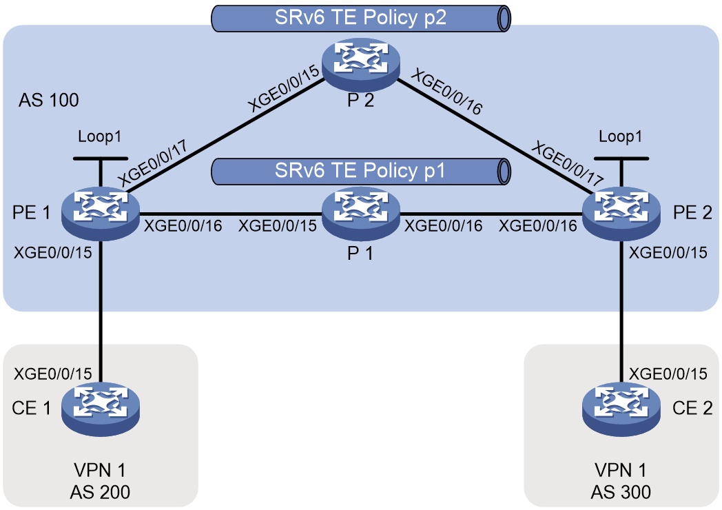
|
Device |
Interface |
IP address |
Device |
Interface |
IP address |
|
CE 1 |
XGE0/0/15 |
10.1.1.1/24 |
CE 2 |
XGE0/0/15 |
20.1.1.1/24 |
|
|
Loopback 1 |
11.11.11.11/32 |
|
Loopback 1 |
22.22.22.22/32 |
|
|
Loopback 2 |
10.10.10.10/32 |
|
Loopback 2 |
20.20.20.20/32 |
|
PE 1 |
Loop1 |
1::1/128 |
PE 2 |
Loop1 |
3::3/128 |
|
|
XGE0/0/15 |
10.1.1.2/24 |
|
XGE0/0/15 |
20.1.1.2/24 |
|
|
XGE0/0/16 |
1001::1/96 |
|
XGE0/0/16 |
2001::1/96 |
|
|
XGE0/0/17 |
3001::1/96 |
|
XGE0/0/17 |
4001::1/96 |
|
P 1 |
Loop1 |
2::2/128 |
P 2 |
Loop1 |
4::4/128 |
|
|
XGE0/0/15 |
1001::2/96 |
|
XGE0/0/15 |
3001::2/96 |
|
|
XGE0/0/16 |
2001::2/96 |
|
XGE0/0/16 |
4001::2/96 |
Procedure
1. Configure CE 1.
<Sysname> system-view
[Sysname] sysname CE1
[CE1] interface ten-gigabitethernet 0/0/15
[CE1-Ten-GigabitEthernet0/0/15] ip address 10.1.1.1 24
[CE1-Ten-GigabitEthernet0/0/15] quit
[CE1] bgp 200
[CE1-bgp-default] peer 10.1.1.2 as-number 100
[CE1-bgp-default] address-family ipv4 unicast
[CE1-bgp-default-ipv4] peer 10.1.1.2 enable
[CE1-bgp-default-ipv4] import-route direct
[CE1-bgp-default-ipv4] quit
[CE1-bgp-default] quit
2. Configure PE 1.
# Configure IPv6 IS-IS to achieve PE interconnects in the backbone network.
<Sysname> system-view
[Sysname] sysname PE1
[PE1] isis 1
[PE1-isis-1] cost-style wide
[PE1-isis-1] network-entity 00.0000.0000.0001.00
[PE1-isis-1] address-family ipv6 unicast
[PE1-isis-1-ipv6] quit
[PE1-isis-1] quit
[PE1] interface loopback 1
[PE1-LoopBack1] ipv6 address 1::1 128
[PE1-LoopBack1] isis ipv6 enable 1
[PE1-LoopBack1] quit
[PE1] interface ten-gigabitethernet 0/0/16
[PE1-Ten-GigabitEthernet0/0/16] ipv6 address 1001::1 96
[PE1-Ten-GigabitEthernet0/0/16] isis ipv6 enable 1
[PE1-Ten-GigabitEthernet0/0/16] quit
[PE1] interface ten-gigabitethernet 0/0/17
[PE1-Ten-GigabitEthernet0/0/17] ipv6 address 3001::1 96
[PE1-Ten-GigabitEthernet0/0/17] isis ipv6 enable 1
[PE1-Ten-GigabitEthernet0/0/17] quit
# Configure a VPN instance that connects CE 1 to PE 1.
[PE1] ip vpn-instance vpn1
[PE1-vpn-instance-vpn1] route-distinguisher 100:1
[PE1-vpn-instance-vpn1] vpn-target 100:1
[PE1-vpn-instance-vpn1] quit
[PE1] interface ten-gigabitethernet 0/0/15
[PE1-Ten-GigabitEthernet0/0/15] ip binding vpn-instance vpn1
[PE1-Ten-GigabitEthernet0/0/15] ip address 10.1.1.2 24
[PE1-Ten-GigabitEthernet0/0/15] quit
# Establish an EBGP peer relationship between PE 1 and CE 1, and enable the PE to redistribute VPN routes to BGP.
[PE1] bgp 100
[PE1-bgp-default] router-id 1.1.1.1
[PE1-bgp-default] ip vpn-instance vpn1
[PE1-bgp-default-vpn1] peer 10.1.1.1 as-number 200
[PE1-bgp-default-vpn1] address-family ipv4 unicast
[PE1-bgp-default-ipv4-vpn1] peer 10.1.1.1 enable
[PE1-bgp-default-ipv4-vpn1] import-route direct
[PE1-bgp-default-ipv4-vpn1] quit
[PE1-bgp-default-vpn1] quit
[PE1-bgp-default] quit
# Create and activate IPv4 Flowspec rules on PE 1, and then advertise them to PE 2. PE 2 will generate the following traffic forwarding policies:
¡ Redirect private network traffic destined for 11.11.11.11 to SRv6 TE policy p1 (color value: 10).
¡ Redirect private network traffic destined for 10.10.10.10 to SRv6 TE policy p2 (color value: 20).
[PE1] flow-route abc1
[PE1-flow-route-abc1] if-match destination-ip 11.11.11.11 32
[PE1-flow-route-abc1] if-match source-ip 22.22.22.22 32
[PE1-flow-route-abc1] apply redirect next-hop 1::1 color 00:10 sid 100:1::A
[PE1-flow-route-abc1] commit
[PE1-flow-route-abc] quit
[PE1] flow-route abc2
[PE1-flow-route-abc2] if-match destination-ip 10.10.10.10 32
[PE1-flow-route-abc2] if-match source-ip 20.20.20.20 32
[PE1-flow-route-abc2] apply redirect next-hop 1::1 color 00:20 sid 100:1::A
[PE1-flow-route-abc2] commit
[PE1-flow-route-abc2] quit
# Apply IPv4 Flowspec rules to the desired VPN instance.
[PE1] ip vpn-instance vpn1
[PE1-vpn-instance-vpn1] address-family ipv4 flowspec
[PE1-vpn-flowspec-ipv4-vpn1] route-distinguisher 100:1
[PE1-vpn-flowspec-ipv4-vpn1] vpn-target 100:1
[PE1-vpn-flowspec-ipv4-vpn1] quit
[PE1-vpn-instance-vpn1] quit
[PE1] flowspec
[PE1-flowspec] address-family ipv4 vpn-instance vpn1
[PE1-flowspec-ipv4-vpn1] flow-route abc1
[PE1-flowspec-ipv4-vpn1] flow-route abc2
[PE1-flowspec-ipv4-vpn1] quit
[PE1-flowspec] quit
# Establish a BGP VPNv4 Flowspec peer relationship between the PEs. The PEs can then advertise VPNv4 Flowspec routes to each other.
[PE1] bgp 100
[PE1-bgp-default] peer 3::3 as-number 100
[PE1-bgp-default] peer 3::3 connect-interface loopback 1
[PE1-bgp-default] address-family vpnv4 flowspec
[PE1-bgp-default-flowspec-vpnv4] peer 3::3 enable
[PE1-bgp-default-flowspec-vpnv4] quit
[PE1-bgp-default] quit
# Establish a BGP EVPN peer relationship between the PEs.
[PE1-bgp-default] address-family l2vpn evpn
[PE1-bgp-default-evpn] peer 3::3 enable
[PE1-bgp-default-evpn] quit
[PE1-bgp-default] quit
# Recurse the VPN route between PE 1 and PE 2 to the desired SRv6 TE policy.
[PE1] segment-routing ipv6
[PE1-segment-routing-ipv6] encapsulation source-address 1::1
[PE1-segment-routing-ipv6] locator abc ipv6-prefix 100:1:: 64 static 16
[PE1-segment-routing-ipv6-locator-abc] opcode 1 end no-flavor
[PE1-segment-routing-ipv6-locator-abc] opcode 10 end-dt4 vpn-instance vpn1 evpn
[PE1-segment-routing-ipv6-locator-abc] quit
[PE1-segment-routing-ipv6] quit
[PE1] isis 1
[PE1-isis-1] address-family ipv6 unicast
[PE1-isis-1-ipv6] segment-routing ipv6 locator abc
[PE1-isis-1-ipv6] quit
[PE1-isis-1] quit
[PE1] bgp 100
[PE1-bgp-default] address-family l2vpn evpn
[PE1-bgp-default-evpn] peer 3::3 advertise encap-type srv6
[PE1-bgp-default-evpn] quit
[PE1-bgp-default] ip vpn-instance vpn1
[PE1-bgp-default-vpn1] address-family ipv4 unicast
[PE1-bgp-default-ipv4-vpn1] segment-routing ipv6 locator abc evpn
[PE1-bgp-default-ipv4-vpn1] segment-routing ipv6 traffic-engineering best-effort evpn
[PE1-bgp-default-ipv4-vpn1] quit
[PE1-bgp-default-vpn1] quit
[PE1-bgp-default] quit
# Configure SRv6 TE policy p1 with a color value of 10 and SRv6 TE policy p2 with a color value of 20.
[PE1] segment-routing ipv6
[PE1-segment-routing-ipv6] traffic-engineering
[PE1-srv6-te] srv6-policy locator abc
[PE1-srv6-te] segment-list s1
[PE1-srv6-te-sl-s1] index 10 ipv6 200:1::1
[PE1-srv6-te-sl-s1] index 20 ipv6 300:1::1
[PE1-srv6-te-sl-s1] quit
[PE1-srv6-te] segment-list s2
[PE1-srv6-te-sl-s1] index 10 ipv6 400:1::1
[PE1-srv6-te-sl-s1] index 20 ipv6 300:1::1
[PE1-srv6-te-sl-s1] quit
[PE1-srv6-te] policy p1
[PE1-srv6-te-policy-p1] color 10 end-point ipv6 3::3
[PE1-srv6-te-policy-p1] candidate-paths
[PE1-srv6-te-policy-p1-path] preference 10
[PE1-srv6-te-policy-p1-path-pref-10] explicit segment-list s1
[PE1-srv6-te-policy-p1-path-pref-10] quit
[PE1-srv6-te-policy-p1-path] quit
[PE1-srv6-te-policy-p1] quit
[PE1-srv6-te] policy p2
[PE1-srv6-te-policy-p2] color 20 end-point ipv6 3::3
[PE1-srv6-te-policy-p2] candidate-paths
[PE1-srv6-te-policy-p2-path] preference 10
[PE1-srv6-te-policy-p2-path-pref-10] explicit segment-list s2
[PE1-srv6-te-policy-p2-path-pref-10] quit
[PE1-srv6-te-policy-p2-path] quit
[PE1-srv6-te-policy-p2] quit
[PE1-srv6-te] quit
[PE1-segment-routing-ipv6] quit
# Enable SBFD for all SRv6 TE policies.
[PE1] sbfd source-ipv6 1::1
[PE1] bfd multi-hop detect-multiplier 5
[PE1] bfd multi-hop min-transmit-interval 100
[PE1] segment-routing ipv6
[PE1-segment-routing-ipv6] traffic-engineering
[PE1-srv6-te] srv6-policy sbfd remote 1000001
[PE1-srv6-te] quit
[PE1-segment-routing-ipv6] quit
# Configure a tunnel policy to ensure that the preferred tunnel is an SRv6 TE policy and multiple SRv6 TE policies can be used for load sharing.
[PE1] tunnel-policy a
[PE1-tunnel-policy-a] select-seq srv6-policy load-balance-number 2
[PE1-tunnel-policy-a] quit
[PE1] ip vpn-instance vpn1
[PE1-vpn-instance-vpn1] tnl-policy a
[PE1-vpn-instance-vpn1] quit
3. Configure P 1.
# Configure IPv6 IS-IS to achieve PE interconnects in the backbone network.
<Sysname> system-view
[Sysname] sysname P1
[P1] isis 1
[P1-isis-1] cost-style wide
[P1-isis-1] network-entity 00.0000.0000.0002.00
[P1-isis-1] address-family ipv6 unicast
[P1-isis-1-ipv6] quit
[P1-isis-1] quit
[P1] interface loopback 1
[P1-LoopBack1] ipv6 address 2::2 128
[P1-LoopBack1] isis ipv6 enable 1
[P1-LoopBack1] quit
[P1] interface ten-gigabitethernet 0/0/15
[P1-Ten-GigabitEthernet0/0/15] ipv6 address 1001::2 96
[P1-Ten-GigabitEthernet0/0/15] isis ipv6 enable 1
[P1-Ten-GigabitEthernet0/0/15] quit
[P1] interface ten-gigabitethernet 0/0/16
[P1-Ten-GigabitEthernet0/0/16] ipv6 address 2001::2 96
[P1-Ten-GigabitEthernet0/0/16] isis ipv6 enable 1
[P1-Ten-GigabitEthernet0/0/16] quit
# Configure a locator and enable IS-IS to advertise that locator.
[P1] segment-routing ipv6
[P1-segment-routing-ipv6] locator abc ipv6-prefix 200:1:: 64 static 16
[P1-segment-routing-ipv6-locator-abc] opcode 1 end no-flavor
[P1-segment-routing-ipv6-locator-abc] quit
[P1-segment-routing-ipv6] quit
[P1] isis 1
[P1-isis-1] address-family ipv6 unicast
[P1-isis-1-ipv6] segment-routing ipv6 locator abc
[P1-isis-1-ipv6] quit
[P1-isis-1] quit
4. Configure P 2.
# Configure IPv6 IS-IS to achieve PE interconnects in the backbone network.
<Sysname> system-view
[Sysname] sysname P2
[P2] isis 1
[P2-isis-1] cost-style wide
[P2-isis-1] network-entity 00.0000.0000.0004.00
[P2-isis-1] address-family ipv6 unicast
[P2-isis-1-ipv6] quit
[P2-isis-1] quit
[P2] interface loopback 1
[P2-LoopBack1] ipv6 address 4::4 128
[P2-LoopBack1] isis ipv6 enable 1
[P2-LoopBack1] quit
[P2] interface ten-gigabitethernet 0/0/15
[P2-Ten-GigabitEthernet0/0/15] ipv6 address 3001::2 96
[P2-Ten-GigabitEthernet0/0/15] isis ipv6 enable 1
[P2-Ten-GigabitEthernet0/0/15] quit
[P2] interface ten-gigabitethernet 0/0/16
[P2-Ten-GigabitEthernet0/0/16] ipv6 address 4001::2 96
[P2-Ten-GigabitEthernet0/0/16] isis ipv6 enable 1
[P2-Ten-GigabitEthernet0/0/16] quit
# Configure a locator and enable IS-IS to advertise the locator.
[P2] segment-routing ipv6
[P2-segment-routing-ipv6] locator abc ipv6-prefix 400:1:: 64 static 16
[P2-segment-routing-ipv6-locator-abc] opcode 1 end no-flavor
[P2-segment-routing-ipv6-locator-abc] quit
[P2-segment-routing-ipv6] quit
[P2] isis 1
[P2-isis-1] address-family ipv6 unicast
[P2-isis-1-ipv6] segment-routing ipv6 locator abc
[P2-isis-1-ipv6] quit
[P2-isis-1] quit
5. Configure PE 2.
# Configure IPv6 IS-IS to achieve PE interconnects in the backbone network.
<Sysname> system-view
[Sysname] sysname PE2
[PE2] isis 1
[PE2-isis-1] cost-style wide
[PE2-isis-1] network-entity 00.0000.0000.0003.00
[PE2-isis-1] address-family ipv6 unicast
[PE2-isis-1-ipv6] quit
[PE2-isis-1] quit
[PE2] interface loopback 1
[PE2-LoopBack1] ipv6 address 3::3 128
[PE2-LoopBack1] isis ipv6 enable 1
[PE2-LoopBack1] quit
[PE2] interface ten-gigabitethernet 0/0/16
[PE2-Ten-GigabitEthernet0/0/16] ipv6 address 2001::1 96
[PE2-Ten-GigabitEthernet0/0/16] isis ipv6 enable 1
[PE2-Ten-GigabitEthernet0/0/16] quit
[PE2] interface ten-gigabitethernet 0/0/17
[PE2-Ten-GigabitEthernet0/0/17] ipv6 address 4001::1 96
[PE2-Ten-GigabitEthernet0/0/17] isis ipv6 enable 1
[PE2-Ten-GigabitEthernet0/0/17] quit
# Configure a VPN instance that connects CE 2 to PE 2.
[PE2] ip vpn-instance vpn1
[PE2-vpn-instance-vpn1] route-distinguisher 100:1
[PE2-vpn-instance-vpn1] vpn-target 100:1
[PE2-vpn-instance-vpn1] quit
[PE2] interface ten-gigabitethernet 0/0/15
[PE2-Ten-GigabitEthernet0/0/15] ip binding vpn-instance vpn1
[PE2-Ten-GigabitEthernet0/0/15] ip address 20.1.1.2 24
[PE2-Ten-GigabitEthernet0/0/15] quit
# Establish an EBGP peer relationship between PE 2 and CE 2, and enable the PE to redistribute VPN routes to BGP.
[PE2] bgp 100
[PE2-bgp-default] router-id 3.3.3.3
[PE2-bgp-default] ip vpn-instance vpn1
[PE2-bgp-default-vpn1] peer 20.1.1.1 as-number 300
[PE2-bgp-default-vpn1] address-family ipv4 unicast
[PE2-bgp-default-ipv4-vpn1] peer 20.1.1.1 enable
[PE2-bgp-default-ipv4-vpn1] import-route direct
[PE2-bgp-default-ipv4-vpn1] quit
[PE2-bgp-default-vpn1] quit
[PE2-bgp-default] quit
# Create and activate IPv4 Flowspec rules on PE 2, and then advertise them to PE 1. PE 1 will generate the following traffic forwarding policies:
¡ Redirect private network traffic destined for 22.22.22.22 to SRv6 TE policy p1 (color value: 10).
¡ Redirect private network traffic destined for 20.20.20.20 to SRv6 TE policy p2 (color value: 20).
[PE2] flow-route abc1
[PE2-flow-route-abc1] if-match destination-ip 22.22.22.22 32
[PE2-flow-route-abc1] if-match source-ip 11.11.11.11 32
[PE2-flow-route-abc1] apply redirect next-hop 3::3 color 00:10 sid 300:1::A
[PE2-flow-route-abc1] commit
[PE2-flow-route-abc1] quit
[PE2] flow-route abc2
[PE2-flow-route-abc2] if-match destination-ip 20.20.20.20 32
[PE2-flow-route-abc2] if-match source-ip 10.10.10.10 32
[PE2-flow-route-abc2] apply redirect next-hop 3::3 color 00:20 sid 300:1::A
[PE2-flow-route-abc2] commit
[PE2-flow-route-abc2] quit
# Apply IPv4 Flowspec rules to the desired VPN instance.
[PE2] ip vpn-instance vpn1
[PE2-vpn-instance-vpn1] address-family ipv4 flowspec
[PE2-vpn-flowspec-ipv4-vpn1] route-distinguisher 100:1
[PE2-vpn-flowspec-ipv4-vpn1] vpn-target 100:1
[PE2-vpn-flowspec-ipv4-vpn1] quit
[PE2-vpn-instance-vpn1] quit
[PE2] flowspec
[PE2-flowspec] address-family ipv4 vpn-instance vpn1
[PE2-flowspec-ipv4-vpn1] flow-route abc1
[PE2-flowspec-ipv4-vpn1] flow-route abc2
[PE2-flowspec-ipv4-vpn1] quit
[PE2-flowspec] quit
# Establish a BGP VPNv4 Flowspec peer relationship between the PEs.
[PE2] bgp 100
[PE2-bgp-default] peer 1::1 as-number 100
[PE2-bgp-default] peer 1::1 connect-interface loopback 1
[PE2-bgp-default] address-family vpnv4 flowspec
[PE2-bgp-default-flowspec-vpnv4] peer 1::1 enable
[PE2-bgp-default-flowspec-vpnv4] quit
[PE2-bgp-default] quit
# Establish a BGP EVPN peer relationship between the PEs.
[PE2-bgp-default] address-family l2vpn evpn
[PE2-bgp-default-evpn] peer 1::1 enable
[PE2-bgp-default-evpn] quit
[PE2-bgp-default] quit
# Recurse the VPN route between PE 2 and PE 1 to the desired SRv6 TE policy.
[PE2] segment-routing ipv6
[PE2-segment-routing-ipv6] encapsulation source-address 3::3
[PE2-segment-routing-ipv6] locator abc ipv6-prefix 300:1:: 64 static 16
[PE2-segment-routing-ipv6-locator-abc] opcode 1 end no-flavor
[PE2-segment-routing-ipv6-locator-abc] opcode 10 end-dt4 vpn-instance vpn1 evpn
[PE2-segment-routing-ipv6-locator-abc] quit
[PE2-segment-routing-ipv6] quit
[PE2] isis 1
[PE2-isis-1] address-family ipv6 unicast
[PE2-isis-1-ipv6] segment-routing ipv6 locator abc
[PE2-isis-1-ipv6] quit
[PE2-isis-1] quit
[PE2] bgp 100
[PE2-bgp-default] address-family l2vpn evpn
[PE2-bgp-default-evpn] peer 1::1 advertise encap-type srv6
[PE2-bgp-default-evpn] quit
[PE2-bgp-default] ip vpn-instance vpn1
[PE2-bgp-default-vpn1] address-family ipv4 unicast
[PE2-bgp-default-ipv4-vpn1] segment-routing ipv6 locator abc evpn
[PE2-bgp-default-ipv4-vpn1] segment-routing ipv6 traffic-engineering best-effort evpn
[PE2-bgp-default-ipv4-vpn1] quit
[PE2-bgp-default-vpn1] quit
[PE2-bgp-default] quit
# Configure SRv6 TE policy p1 with a color value of 10 and SRv6 TE policy p2 with a color value of 20.
[PE2] segment-routing ipv6
[PE2-segment-routing-ipv6] traffic-engineering
[PE2-srv6-te] srv6-policy locator abc
[PE2-srv6-te] segment-list s1
[PE2-srv6-te-sl-s1] index 10 ipv6 200:1::1
[PE2-srv6-te-sl-s1] index 20 ipv6 100:1::1
[PE2-srv6-te-sl-s1] quit
[PE2-srv6-te] segment-list s2
[PE2-srv6-te-sl-s1] index 10 ipv6 400:1::1
[PE2-srv6-te-sl-s1] index 20 ipv6 100:1::1
[PE2-srv6-te-sl-s1] quit
[PE2-srv6-te] policy p1
[PE2-srv6-te-policy-p1] color 10 end-point ipv6 1::1
[PE2-srv6-te-policy-p1] candidate-paths
[PE2-srv6-te-policy-p1-path] preference 10
[PE2-srv6-te-policy-p1-path-pref-10] explicit segment-list s1
[PE2-srv6-te-policy-p1-path-pref-10] quit
[PE2-srv6-te-policy-p1-path] quit
[PE2-srv6-te-policy-p1] quit
[PE2-srv6-te] policy p2
[PE2-srv6-te-policy-p2] color 20 end-point ipv6 1::1
[PE2-srv6-te-policy-p2] candidate-paths
[PE2-srv6-te-policy-p2-path] preference 10
[PE2-srv6-te-policy-p2-path-pref-10] explicit segment-list s2
[PE2-srv6-te-policy-p2-path-pref-10] quit
[PE2-srv6-te-policy-p2-path] quit
[PE2-srv6-te-policy-p2] quit
[PE2-srv6-te] quit
[PE2-segment-routing-ipv6] quit
# Configure the local discriminator for the reflector in the SBFD session.
[PE2] sbfd local-discriminator 1000001
6. Configure CE 2.
<Sysname> system-view
[Sysname] sysname CE2
[CE2] interface ten-gigabitethernet 0/0/15
[CE2-Ten-GigabitEthernet0/0/15] ip address 20.1.1.1 24
[CE2-Ten-GigabitEthernet0/0/15] quit
[CE2] bgp 300
[CE2-bgp-default] peer 20.1.1.2 as-number 100
[CE2-bgp-default] address-family ipv4 unicast
[CE2-bgp-default-ipv4] peer 20.1.1.2 enable
[CE2-bgp-default-ipv4] import-route direct
[CE2-bgp-default-ipv4] quit
[CE2-bgp-default] quit
Verifying the configuration
# On PE 1, execute the display segment-routing ipv6 te policy command to view detailed information about SRv6 TE policies. The command output shows that the Status field of SRv6 TE policy p1 is Up. You can record the Forwarding index field of SRv6 TE policy p1 and then verify that this value is the same as the index of the forwarding policy to which the flow rule redirects traffic.
<PE1> display segment-routing ipv6 te policy
Name/ID: p1/0
Color: 10
End-point: 3::3
Name from BGP:
BSID:
Mode: Dynamic Type: Type_2 Request state: Succeeded
Current BSID: 100:1::1:3 Explicit BSID: - Dynamic BSID: 100:1::1:3
Reference counts: 4
Flags: A/BS/NC
Status: Up
AdminStatus: Up
Up time: 2023-11-23 19:31:35
Down time: 2023-11-23 19:27:37
…
Forwarding index: 2150629377
…
Explicit SID list:
ID: 1 Name: s1
Weight: 1 Forwarding index: 2149580802
State: Up State(SBFD): Up
Active path MTU: 1428 bytes
# On PE 1, execute the display ip routing-table vpn-instance vpn1 command to view detailed information about VPN routes. The command output shows that each VPN route has two equal-cost output interfaces, SRv6 TE policy p1 and SRv6 TE policy p2.
<PE1> display ip routing-table vpn-instance vpn1
Destinations : 3 Routes : 3
Destination/Mask Proto Pre Cost NextHop Interface
20.1.1.0/24 BGP 255 0 3::3 p1
BGP 255 0 3::3 p2
20.20.20.20/32 BGP 255 0 3::3 p1
BGP 255 0 3::3 p2
22.22.22.22/32 BGP 255 0 3::3 p1
BGP 255 0 3::3 p2
# On PE 1, execute the display bgp routing-table ipv4 flowspec vpn-instance vpn1 command to view information about VPN Flowspec routes. The command output shows that PE 1 received Flowspec route 22.22.22.22 from PE 2, which is valid and optimal.
<PE1> display bgp routing-table ipv4 flowspec vpn-instance vpn1
Total number of routes: 2
BGP local router ID is 1.1.1.1
Status codes: * - valid, > - best, d - dampened, h - history,
s - suppressed, S - stale, i - internal, e - external
a - additional-path
Origin: i - IGP, e - EGP, ? - incomplete
Network NextHop MED LocPrf PrefVal Path/Ogn
* > DEST:11.11.11.11/32,Source:22.22.22.22/32/96
1::1 32768 i
* >i DEST:22.22.22.22/32,Source:11.11.11.11/32/96
3::3 100 0 i
# On PE 1, execute the display bgp routing-table ipv4 flowspec vpn-instance vpn1 command to view detailed information about Flowspec route 22.22.22.22. According to the command output, VPN packets with a source address of 11.11.11.11 and a destination address of 22.22.22.22 will be redirected to 3::3 and labeled with an VPN SID of 300:1::A.
<PE1> display bgp routing-table ipv4 flowspec vpn-instance vpn1 DEST:
22.22.22.22/32,Source:11.11.11.11/32/96
BGP local router ID: 1.1.1.1
Local AS number: 100
Paths: 1 available, 1 best
BGP routing table information of DEST:22.22.22.22/32,Source:11.11.11.11/32/96:
From : 3::3 (3.3.3.3)
Original nexthop: 0.0.0.0
Out interface : NULL0
Route age : 01h03m24s
OutLabel : NULL
Ext-Community : <RT: 100:1>, <CO-Flag:Color(00:10)>
Ext-comm-ipv6 : <FLOWSPEC REDIRECT-IP: 3::3 & 0>
RxPathID : 0x0
TxPathID : 0x0
PrefixSID : N/A SID <300:1::A>
SRv6 Service TLV (37 bytes):
Type: SRV6 L3 Service TLV (5)
Length: 34 bytes, Reserved: 0x0
SRv6 Service Information Sub-TLV (33 bytes):
Type: 1 Length: 30, Rsvdl: 0x0
SID Flags: 0x0 Endpoint behavior: 0x0 Rsvd2: 0x0
SRv6 SID Sub-Sub-TLV:
Type: 1 Len: 6
BL: 0 NL: 0 FL: 0 AL: 0 TL: 0 TO: 0
AS-path : (null)
Origin : igp
Attribute value : localpref 100, pref-val 0
State : valid, internal, best
Source type : local
IP precedence : N/A
QoS local ID : N/A
Traffic index : N/A
# On PE 1, execute the display flow-route ipv4 vpn-instance vpn1 command to view the local Flowspec rules. The Forwarding ID field displays the index of a forwarding entry. According to the command output, the forwarding entry index for VPN route 20.20.20.20 equals the forwarding entry index of SRv6 TE policy p2, and the forwarding entry index for VPN route 22.22.22.22 equals the forwarding entry index of SRv6 TE policy p1.
<PE1> display flow-route ipv4 vpn-instance vpn1
Total number of flow-routes: 4
…
Flow route (ID 0x3)
BGP instance : default
VPN instance : vpn1
Traffic filtering rules:
Destination IP : 20.20.20.20 255.255.255.255
Source IP : 10.10.10.10 255.255.255.255
Traffic filtering actions:
Redirecting to SRv6-TE policy
Forwarding ID: 2150629378
SID : 300:1::A
Flow route (ID 0x1)
BGP instance : default
VPN instance : vpn1
Traffic filtering rules:
Destination IP : 22.22.22.22 255.255.255.255
Source IP : 11.11.11.11 255.255.255.255
Traffic filtering actions:
Redirecting to SRv6-TE policy
Forwarding ID: 2150629377
SID : 300:1::A
# Ping packets with different source addresses between CE 1 and CE 2 to simulate forwarding of different services’ traffic. By capturing packets, you can find that traffic of different services is forwarded through different SRv6 TE policies.
<CE1> ping -a 11.11.11.11 22.22.22.22
Ping 22.22.22.22 (22.22.22.22) from 11.11.11.11: 56 data bytes, press CTRL+C to break
56 bytes from 22.22.22.22: icmp_seq=0 ttl=253 time=2.000 ms
56 bytes from 22.22.22.22: icmp_seq=1 ttl=253 time=2.000 ms
56 bytes from 22.22.22.22: icmp_seq=2 ttl=253 time=2.000 ms
56 bytes from 22.22.22.22: icmp_seq=3 ttl=253 time=2.000 ms
56 bytes from 22.22.22.22: icmp_seq=4 ttl=253 time=2.000 ms
--- Ping statistics for 22.22.22.22 ---
5 packet(s) transmitted, 5 packet(s) received, 0.0% packet loss
round-trip min/avg/max/std-dev = 2.000/2.000/2.000/0.000 ms
# After you complete the ping test, execute the display flowspec statistics command on PE 1 to view the traffic statistics collected for Flowspec rules.
Appendix
SRv6 TE Policy NLRI
SRv6 TE Policy NLRI
The SRv6 TE Policy NLRI describes the reachability of SRv6 SIDs at the network layer.
Figure 41 shows the format of the SRv6 TE Policy NLRI.

The SRv6 TE Policy NLRI contains the following fields:
Table 4 Fields in SRv6 TE Policy NLRI
|
Field |
Length |
Description |
|
NLRI Length |
8 bits |
Length of the SRv6 policy NLRI. |
|
Distinguisher |
32 bits |
Unique ID of the SRv6 TE policy. |
|
Policy Color |
32 bits |
Color attribute of the SRv6 TE policy. |
|
Endpoint |
128 bits |
Destination node address of the SRv6 TE policy. |
Tunnel Encapsulation Attribute
The Tunnel Encapsulation Attribute always appears in conjunction with the SRv6 TE Policy NLRI in a BGP UPDATE message. As shown in Table 5, the Tunnel Encapsulation Attribute uses the following sub-TLVs to record SRv6 TE policy information.
Table 5 Sub-TLVs in Tunnel Encapsulation Attribute
|
TLV |
Description |
Location |
|
Preference Sub-TLV |
Announces the priority of a candidate path. |
Tunnel Encapsulation Attribute |
|
SRv6 Binding SID Sub-TLV |
Announces the BSID of a candidate path. |
Tunnel Encapsulation Attribute |
|
Segment List Sub-TLV |
Announces a segment list |
Tunnel Encapsulation Attribute |
|
Weight Sub-TLV |
Announces the weight of a segment List. |
Segment List Sub-TLV |
|
Policy Candidate Path Name Sub-TLV |
Announces the name of a candidate path. |
Tunnel Encapsulation Attribute |
Preference Sub-TLV
The Preference Sub-TLV contains priority information of candidate paths.
Figure 42 shows the format of the Preference Sub-TLV.
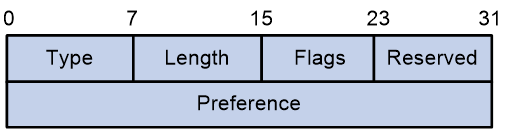
The Preference Sub-TLV contains the following fields:
Table 6 Fields in Preference Sub-TLV
|
Field |
Length |
Description |
|
8 bits |
Type value, which is 12. |
|
|
Length |
8 bits |
Length. |
|
Flags |
8 bits |
Flags, which are currently undefined. |
|
Reserved |
8 bits |
Reserved value, which is fixed at 0. |
|
Preference |
32 bits |
Preference value for candidate paths in the SRv6 TE policy. |
Binding SID Sub-TLV
The Binding SID Sub-TLV identifies the BSID of an SRv6 TE policy.
Figure 43 shows the format of the Binding SID Sub-TLV.
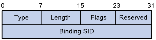
The Binding SID Sub-TLV contains the following fields:
Table 7 Fields in Binding SID Sub-TLV
|
Field name |
Length |
Description |
|
8 bits |
Type value, which is 13. |
|
|
Length |
8 bits |
Length. |
|
Flags |
8 bits |
Flags, which are currently undefined. |
|
Reserved |
8 bits |
|
|
Binding SID |
32 bits |
BSID. |
Segment List Sub-TLV
The Segment List Sub-TLV contains the segment lists of a candidate path.
Figure 44 shows the format of the Segment List Sub-TLV.
Figure 44 Segment List Sub-TLV
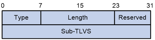
The Segment List Sub-TLV contains the following fields:
Table 8 Fields in Segment List Sub-TLV
|
Field name |
Length |
Description |
|
8 bits |
Type value, which is 128. |
|
|
Length |
16 bits |
Length. |
|
Reserved |
8 bits |
Reserved value, which is fixed at 0. |
|
Sub-TLVs |
32 bits |
· One optional Weight sub-TLV. · Zero, one, or multiple Segment sub-TLVs. |
Weight Sub-TLV
The Weight Sub-TLV contains the weight information of a segment list.
Figure 45 shows the format of the Weight Sub-TLV.
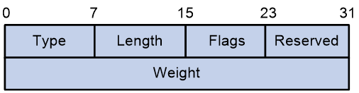
The Weight Sub-TLV contains the following fields:
Table 9 Fields in Weight Sub-TLV
|
Field |
Length |
Description |
|
Type |
8 bits |
Type value, which is 9. |
|
Length |
8 bits |
Length. |
|
Flags |
8 bits |
Flags. |
|
Reserved |
8 bits |
Reserved value, which is fixed at 0. |
|
Weight |
32 bits |
Weight value of the segment list. |
TE Policy NLRI in BGP-LS routes
TE Policy NLRI
BGP-LS summarizes topology information collected by IGPs and reports it to the controller. This allows the controller to obtain the entire network topology and calculate optimal paths based on it.
Before the introduction of BGP-LS, the controller relied on IGP (OSPF, OSPFv3 or IS-IS) flooding to collect network topology information. When multiple IGP routing domain exist, the IGP reports topology information to the controller on a per domain basis. If multiple IGPs run in the network, the controller needs to support those IGPs. BGP-LS significantly simplifies the collection of topology information, because it can collect topology information of each AS and report the collected information to the controller. The controller only needs to support for BGP-LS even if multiple IGPs run in the network.
Aiming to facilitate topology information collection, BGP-LS has introduced a series of new NLRIs (Network Layer Reachability Information) to carry link, node, and IPv4/IPv6 prefix information. Those NLRIs are called Link-State NLRIs, which are defined in RFC 7752 as follows:
· Node NLRI with a Type value of 1.
· Link NLRI with a Type value of 2.
· IPv4 Topology Prefix NLRI with a Type value of 3.
· IPv6 Topology Prefix NLRI with a Type value of 4.
According to draft-ietf-idr-te-lsp-distribution and draft-ietf-idr-bgp-ls-sr-policy, TE policy (including SRv6 TE policy, SR-MPLS TE Policy, and RSVP-TE) information is also carried by the Link-State NLRI, and its Type value is 5. The format of the TE Policy NLRI is as follows:
Figure 46 TE Policy NLRI
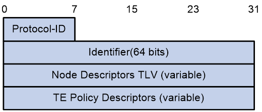
The TE Policy NLRI contains the following fields:
Table 10 Fields in TE Policy NLRI
|
Field |
Length |
Description |
|
Protocol-ID |
8 bits |
Protocol ID. BGP-LS learns the TE Policy information of a node via the specified protocol. 8—RSVP-TE 9—Segment Routing. |
|
Identifier |
64 bits |
Node identifier. |
|
Node Descriptors |
Variable |
Description of the ingress node. |
|
TE Policy Descriptors |
Variable |
TE policy information. SRv6 TE policy-related NLRIs must carry the SR Policy Candidate Path Descriptor TLV. |
SR Policy Candidate Path Descriptor TLV
SRv6 TE policy-related NLRIs must carry the SR Policy Candidate Path Descriptor TLV. The format of this TLV is as follows:
Figure 47 SR Policy Candidate Path Descriptor TLV
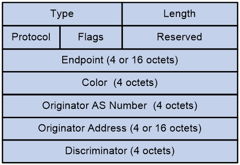
The SR Policy Candidate Path Descriptor TLV contains the following fields:
Table 11 Fields in SR Policy Candidate Path Descriptor TLV
|
Field |
Length |
Description |
|
Type |
16 bits |
Type value, which is 554. |
|
Length |
16 bits |
Length, which is 24, 36, or 48 bytes. |
|
Protocol |
8 bits |
Protocol through which the candidate paths were generated: · PCEP. · BGP. · Static configuration (NETCONF or CLI). |
|
Flags |
8 bits |
Flag. |
|
Reserved |
8 bits |
Reserved bits, which are all-zero. |
|
Endpoint |
32 or 128 bits |
Destination node of the SRv6 TE policy. |
|
Color |
32 bits |
Color attribute of the SRv6 TE policy. |
|
Originator AS Number |
32 bits |
Autonomous system in which the candidate paths were generated. |
|
Originator Address |
32 bits or 128 bits |
Address of the device that generated the candidate paths. |
|
Discriminator |
32 bits |
Candidate path identifier. |
In addition to the SR Policy Candidate Path Descriptor TLV, BGP-LS has defined various optional non-transitive attributes for the TE Policy NLRI to announce additional SRv6 TE policy information such as candidate path state.
Table 12 shows the extensions that BGP-LS has made for SRv6 TE Policy.
Table 12 BGP-LS extensions for SRv6 TE Policy
|
TLV |
Description |
Location |
|
SR Binding SID TLV |
Announces the BSID of the candidate paths in an SRv6 TE policy. A BSID can either be a 4-byte MPLS label or a 16-byte SRv6 SID. |
TE Policy NLRI |
|
SRv6 Binding SID TLV |
Announces the BSID of the candidate paths in an SRv6 TE policy. The BSID length is fixed at 16 bytes. |
TE Policy NLRI |
|
SR Candidate Path State TLV |
Announces the attribute and state information of the candidate paths in an SRv6 TE policy. |
TE Policy NLRI |
|
SR Policy Name TLV |
Announces the name of an SRv6 TE policy. |
TE Policy NLRI |
|
SR Candidate Path Name TLV |
Announces the name of an SRv6 TE policy candidate path. |
TE Policy NLRI |
|
SR Candidate Path Constraints TLV |
TE Policy NLRI |
|
|
SR Affinity Constraint Sub-TLV |
Announces the affinities of an SRv6 TE policy candidate path. |
SR Candidate Path Constraints TLV |
|
SR SRLG Constraint Sub-TLV |
Announces the shared risk link group (SRLG) ID of an SRv6 TE policy candidate path. |
SR Candidate Path Constraints TLV |
|
SR Bandwidth Constraint Sub-TLV |
Announces the bandwidth requirements of an SRv6 TE policy candidate path. |
SR Candidate Path Constraints TLV |
|
SR Disjoint Group Constraint Sub-TLV |
Announces the disjoint group ID of an SRv6 TE policy candidate path. |
SR Candidate Path Constraints TLV |
|
SR Bidirectional Group Constraint Sub-TLV |
Announces the bidirectional group ID of an SRv6 TE policy candidate path. |
SR Candidate Path Constraints TLV |
|
SR Metric Constraint Sub-TLV |
Announces the metrics of an SRv6 TE policy candidate path. |
SR Candidate Path Constraints TLV |
|
SR Segment List TLV |
Announces a segment list of an SRv6 TE policy candidate path. |
TE Policy NLRI |
|
SR Segment Sub-TLV |
Announces an SID from a segment list of an SRv6 TE policy candidate path. |
SR Segment List TLV |
SR Binding SID TLV
The SR Binding SID TLV announces the BSID of the candidate paths in an SRv6 TE policy.
Figure 48 SR Binding SID TLV
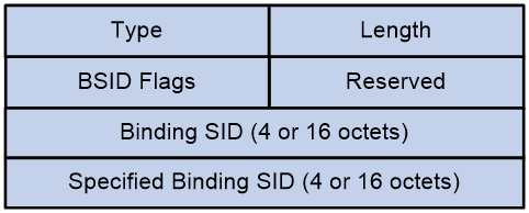
The SR Binding SID TLV contains the following fields:
Table 13 Fields in SR Binding SID TLV
|
Field |
Length |
Description |
|
Type |
16 bits |
Type value, which is 1201. |
|
Length |
16 bits |
Length. |
|
16 bits |
BSID flags with a length of two bytes: · D-Flag: Indicates the type of the BSID: ¡ SRv6 SID. ¡ MPLS label. · B-Flag: Identifies whether the BSID is allocated properly. · U-Flag: Indicates the availability of the specified BSID. · L-Flag: Indicates the source of the BSID: ¡ SRLB. ¡ Dynamic label pool. · F-Flag: Indicates that the specified BSID is unavailable and dynamic allocation is required. |
|
|
Reserved |
16 bits |
Reserved value, which is fixed at 0. |
|
Binding SID |
32 bits or 128 bits |
BSID that is actually used or allocated. It might be manually specified in advance and actually usable, or might be dynamically allocated. |
|
Specified Binding SID |
32 or 128 bits |
Specified BSID. If no BSID is specified, this field displays 0. Even if the specified BSID is unavailable, this field will still display it. |
SRv6 Binding SID TLV
The SRv6 Binding SID TLV announces the BSID of the candidate paths in an SRv6 TE policy.
Figure 49 SRv6 Binding SID TLV.
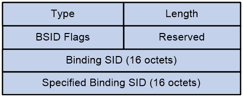
The SRv6 Binding SID TLV contains the following fields:
Table 14 Fields in SRv6 Binding SID TLV
|
Field |
Length |
Description |
|
Type |
16 bits |
|
|
Length |
16 bits |
Length. |
|
BSID Flags |
16 bits |
BSID flags with a length of two bytes: · B-Flag: Identifies whether the BSID is allocated properly. · U-Flag: Indicates the availability of the specified BSID. · F-Flag: Indicates that the specified BSID is unavailable and dynamic allocation is required. |
|
Reserved |
16 bits |
Reserved value, which is fixed at 0. |
|
Binding SID |
128 bits |
BSID that is actually used or allocated. It might be manually specified in advance and actually usable, or might be dynamically allocated. |
|
Specified Binding SID |
128 bits |
Specified BSID. If no BSID is specified, this field displays 0. Even if the specified BSID is unavailable, this field will still display it. |
SR Candidate Path State TLV
The SR Candidate Path State TLV announces the attribute and state information of the candidate paths in an SRv6 TE policy.
Figure 50 SR Candidate Path State TLV
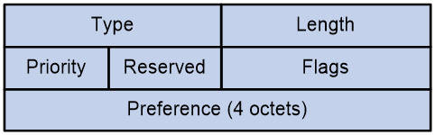
The SR Candidate path State TLV contains the following fields:
Table 15 Fields in SR Candidate Path State TLV
|
Field |
Length |
Description |
|
Type |
16 bits |
Type value, which is 1202. |
|
Length |
16 bits |
Length. |
|
Priority |
8 bits |
Preference value for candidate paths upon path recalculation triggered by a topology change. |
|
Reserved |
8 bits |
Reservation value, which is fixed at 0. |
|
Flags |
16 bits |
State and attribute information of a candidate path: · S-Flag: Indicates that the candidate path is shut down. · A-Flag: Identifies whether the candidate path is active. · B-Flag: Identifies whether the candidate path is standby. · E-Flag: Identifies whether the candidate path has been validated. · V-Flag: Identifies whether the candidate path has a minimum of one valid segment list. · O-Flag: Identifies whether the candidate path is calculated based on an ODN template. · D-Flag: Identifies whether the candidate path is delegated to the PCE or controller for calculation. · C-Flag: Identifies whether the candidate path is issued by the PCE or controller. · I-Flag: Identifies whether the device discards packets when the following conditions exist: ¡ The candidate path is the optimal path and it is the only candidate path in the SRv6 TE policy. ¡ The candidate path becomes invalid. · T-Flag: Indicates that the SRv6 TE policy can be used for label stitching on the ingress node. · U-Flag: Indicates that the SRv6 TE policy to which the candidate path belongs is discarding traffic, because all of its candidate paths are invalid. |
|
Preference |
32 bits |
Preference of the candidate path. |
SR Policy Name TLV
The SR Policy Name TLV announces the name of an SRv6 TE policy.
Figure 51 SR Policy Name TLV
![]()
The SR Policy Name TLV contains the following fields:
Table 16 Fields in SR Policy Name TLV
|
Field |
Length |
Description |
|
Type |
16 bits |
Type value, which is 1213. |
|
Length |
16 bits |
Length. |
|
SR Policy Name |
Variable |
Name of the SRv6 TE policy. |
SR Candidate Path Name TLV
The SR Candidate Path Name TLV announces the name of an SRv6 TE policy candidate path.
Figure 52 SR Candidate Path Name TLV
![]()
The SR Candidate Path Name TLV contains the following fields:
Table 17 Fields in SR Candidate Path Name TLV
|
Field |
Length |
Description |
|
Type |
16 bits |
Type value, which is 1203. |
|
Length |
16 bits |
Length. |
|
Candidate Path Name |
Variable |
Name of the SRv6 TE policy candidate path. |
SR Candidate Path Constraints TLV
The SR Candidate path Constraints TLV announces the constraints for SRv6 TE policy candidate paths, which are typically used for candidate path calculation by the ingress node.
Figure 53 SR Candidate Path Constraints TLV
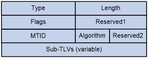
The SR Candidate path Constraints TLV contains the following fields:
Table 18 Fields in SR Candidate path Constraints TLV
|
Field |
Length |
Description |
|
Type |
16 bits |
Type value, which is 1204. |
|
Length |
16 bits |
Length. |
|
Flags |
16 bits |
Constraint conditions of the candidate path. · D-Flag: Indicates the forwarding plane type of the candidate path : ¡ SRv6-based. ¡ SR-MPLS-based. · P-Flag: Indicates that the candidate path's SID lists prefer protection SIDs. · U-Flag: Indicates that the candidate path's SID lists prefer non-protection SIDs. · A-Flag: Indicates that the SIDs in the candidate path's SID lists belong to the specified flexible algorithm. · T-Flag: Indicates that the SIDs in the candidate path's SID lists belong to the specified topology. · S-Flag: Indicates that the candidate path's SID lists strictly require protection SIDs or non-protection SIDs. · F-Flag: Indicates that the candidate path is fixed once calculated. It will not change unless edited by an operator. |
|
Reserved1 |
16 bits |
Reserved value, which is fixed at 0. |
|
16 bits |
IGP topology ID. · If the T-Flag is set, only the specified IGP topology ID can be used for candidate path calculation. · If the T-Flag is not set, the specified IGP topology ID is preferentially used for candidate path calculation. If the calculation fails, other IGP topology IDs can be used to continue the calculation. |
|
|
Algorithm |
8 bits |
Flexible algorithm ID. · If the A-Flag is set, only the specified flexible algorithm can be used for candidate path calculation. · If the A-Flag is not set, the specified flexible algorithm is preferentially used for candidate path calculation. If the calculation fails, other flexible algorithms can be used to continue the calculation. |
|
Reserved2 |
8 bits |
Reserved value, which is fixed at 0. |
|
Sub-TLVs |
Variable |
Sub-TLVs describing the TE constraints for candidate paths. |
SR Segment List TLV
The SR Segment List TLV announces a segment list of an SRv6 TE policy candidate path.
Figure 54 SR Segment List TLV

The SR Segment List TLV contains the following fields:
Table 19 Fields in SR Segment List TLV
|
Field |
Length |
Description |
|
Type |
16 bits |
Type value, which is 1205. |
|
Length |
16 bits |
Length. |
|
Flags |
16 bits |
State information of the segment list. · D-Flag: Indicates that the segment list consists of SRv6 SIDs or MPLS labels. · E-Flag: Indicates that the segment list is a static explicit path or dynamic path. · C-Flag: This flag is set if the segment list is calculated for a dynamic path. This flag is always set for a static explicit path. · V-Flag: Indicates that the segment list has passed path validation, or segment list validation is not enabled. · R-Flag: Identifies whether the first SID in the segment list is reachable. · F-Flag: Indicates that dynamic calculation of the segment list failed. · A-Flag: Indicates that all SIDs in the segment list belong to the same flexible algorithm. · T-Flag: Indicates that all SIDs in the segment list belong to the same topology instance. · M-Flag: Indicates that the segment list was uninstalled from a forwarding entry due to a detection failure (such as BFD failure). |
|
Reserved1 |
16 bits |
Reserved value, which is fixed at 0. |
|
MTID |
16 bits |
IGP topology ID. · If the T-Flag is set, only the specified IGP topology ID can be used for candidate path calculation. · If the T-Flag is not set, the specified IGP topology ID is preferentially used for candidate path calculation. If the calculation fails, other IGP topology IDs can be used to continue the calculation. |
|
Algorithm |
8 bits |
Flexible algorithm ID. · If the A-Flag is set, only the specified flexible algorithm can be used for candidate path calculation. · If the A-Flag is not set, the specified flexible algorithm is preferentially used for candidate path calculation. If the calculation fails, other flexible algorithms can be used to continue the calculation. |
|
Reserved2 |
8 bits |
Reserved value, which is fixed at 0. |
|
Weight |
32 bits |
Weight value for the segment list. |
|
Sub-TLV |
Variable. |
Sub-TLV for the segment list. |
