- Table of Contents
-
- 10-Segment Routing Configuration Guide
- 00-Preface
- 01-SR-MPLS configuration
- 02-SR-MPLS TE policy configuration
- 03-SRv6 configuration
- 04-SRv6 TE policy configuration
- 05-SRv6 VPN overview
- 06-IP L3VPN over SRv6 configuration
- 07-EVPN L3VPN over SRv6 configuration
- 08-EVPN VPWS over SRv6 configuration
- 09-EVPN VPLS over SRv6 configuration
- 10-Public network IP over SRv6 configuration
- 11-SRv6 OAM configuration
- 12-SRv6 network slicing configuration
- 13-SRv6 service chain configuration
- Related Documents
-
| Title | Size | Download |
|---|---|---|
| 06-IP L3VPN over SRv6 configuration | 1.34 MB |
Configuring IP L3VPN over SRv6
Intercommunication between SRv6 and MPLS networks
Intercommunication between SRv6 and EVPN L3VPN networks
SRv6 VPN cross-AS intercommunication
Cross-AS Option B (without requiring VPN instance deployment for the border device)
Restrictions and guidelines: IP L3VPN over SRv6 configuration
IP L3VPN over SRv6 tasks at a glance
Configuring SRv6 SIDs for a COC16-type locator
Applying a locator to a BGP VPN instance
Configuring PEs to exchange BGP VPNv4 or VPNv6 routes
Configuring IPv6 peers to exchange SRv6 SIDs
Configuring next hop-based dynamic End.DX4 or End.DX6 SID allocation for BGP private network routes
Configuring BGP VPNv4 or VPNv6 routes
Restrictions and guidelines for BGP VPNv4 or VPNv6 route configuration
Controlling BGP VPNv4 or VPNv6 route advertisement and reception
Setting a preferred value for received BGP VPNv4 or VPNv6 routes
Configuring BGP VPNv4 or VPNv6 route reflection
Configuring BGP VPNv4 or VPNv6 route attributes
Configuring BGP VPNv4 or VPNv6 route distribution filtering policies
Configuring the BGP Additional Paths feature
Configuring BGP to preferentially use the routes learned from a peer or peer group
Configuring the route recursion mode
Specifying a source address for the outer IPv6 header of SRv6-encapsulated packets
Enabling SRv6 VPN compatibility for a peer or peer group
Configuring optimal route reorigination and advertisement
Modifying BGP VPNv4 or VPNv6 routes
Configuring inter-AS option B VPN
Enabling intercommunication between SRv6 and EVPN L3VPN networks
Configuring transit proxies for SRv6 SIDs in cross-AS IP L3VPN over SRv6 networks
Configuring SRv6 VPN Option B cross-AS intercommunication
Configuring IP L3VPN over SRv6 FRR
Configuring SBFD for SRv6 locators
Configuring a TTL processing mode for tunnels associated with a VPN instance
Display and maintenance commands for IP L3VPN over SRv6
Displaying and maintaining the running status of IP L3VPN over SRv6 VPN
IP L3VPN over SRv6 configuration examples
Example: Configuring IP L3VPN over SRv6 BE
Example: Configuring IPv4 L3VPN over G-SRv6 (with COC32 locators of 32-bit G-SRv6 compression)
Example: Configuring IPv4 L3VPN over G-SRv6 (with COC-both locators of 32-bit G-SRv6 compression)
Example: Configuring IPv4 L3VPN over G-SRv6 (with COC16 locators of 16-bit G-SRv6 compression)
Example: Configuring IPv4 L3VPN HoVPN over MPLS-to-SRv6
Example: Configuring inter-AS option B VPN
Configuring IP L3VPN over SRv6
About IP L3VPN over SRv6
IP L3VPN over SRv6 uses SRv6 tunnels to carry IP L3VPN services. This technology establishes SRv6 tunnels among geographically dispersed customer sites over an IPv6 network and transparently forwards Layer 3 customer traffic to remote sites over the IPv6 network through the tunnels. For more information about MPLS L3VPN configuration, see MPLS Configuration Guide.
Basic principle
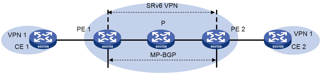
Figure 1 shows a typical IP L3VPN over SRv6 network.
· PE 1 and PE 2 use BGP to advertise IPv4 or IPv6 VPN routes to each other over the IPv6 backbone network. The VPN routes contain private network routing information and SID information.
· The PEs have a single-hop SRv6 tunnel between them and they use the SRv6 tunnel to forward VPN traffic across sites.
· The devices in the IPv6 backbone network forward the SRv6-encapsulated VPN traffic through the optimal path calculated by IGP.
IP L3VPN over SRv6 connects geographically dispersed sites that belong to the same VPN over the IPv6 backbone network.
If the customer sites belong to the public network, IP L3VPN over SRv6 takes the public network as a special VPN. The PEs establish a single-hop SRv6 tunnel between them and use the SRv6 tunnel to forward public network traffic across sites. This scenario is also called the public network over SRv6 scenario.
Route advertisement
The route advertisement process of IPv4 L3VPN over SRv6 is similar to that of IPv6 L3VPN over SRv6. This section uses IPv4 L3VPN over SRv6 to illustrate the process.
As shown in the network diagram in "Basic principle," local routes of CE 1 are advertised to CE 2 by using the following process:
1. CE 1 uses static routing, RIP, OSPF, IS-IS, EBGP, or IBGP to advertise routes of the local site to PE 1.
2. After learning the route information of CE 1, PE 1 stores the private routes to the routing table of the VPN instance. In this example, VPN instance 1 is used. Then, PE 1 converts the routes to BGP VPNv4 routes and advertises the BGP VPNv4 routes to PE 2 by using MP-BGP. The BGP VPNv4 routes carry the RD, RT, and SID attributes (the SID attribute is used as the private network label).
¡ If next hop-based dynamic SID allocation is not used, all private network routes of the VPN instance are allocated the same End.DT4 or End.DT46 SID.
¡ If next hop-based dynamic SID allocation is used, private network routes with the same next hop are allocated the same End.DX4 SID in the VPN instance.
3. When PE 2 receives the routes advertised by PE 1, it adds the routes to the routing table of VPN 1, converts the routes to IPv4 routes, and advertises the IPv4 routes to CE 2.
4. By adding the received IPv4 routes to the routing table, CE 2 learns the private network routes of CE 1.
Packet forwarding
IP L3VPN over SRv6 supports the following route recursion modes:
· SRv6 BE mode.
· SRv6 TE mode.
· SRv6 TE and SRv6 BE hybrid mode.
· SRv6 TE and SRv6 BE FRR mode.
The packet forwarding process differs by the route recursion mode in use.
SRv6 BE mode
This mode is also called SID-based forwarding mode. In this mode, a PE forwards an SRv6 packet by searching the IPv6 routing table based on the SRv6 SID encapsulated in the packet.
The packet forwarding process is similar for IPv4 L3VPN over SRv6 and IPv6 L3VPN over SRv6. This section uses IPv4 L3VPN over SRv6 and VPN sites to illustrate the process.
As shown in Figure 1, CE 2 forwards an IPv4 packet to CE 1 as follows:
1. CE 2 sends the IPv4 packet to PE 2.
2. PE 2 receives the packet on an interface associated with the VPN instance (in this example, the VPN instance is VPN 1). PE 2 searches for a route that matches the destination IPv4 address of the packet in the routing table of the VPN instance. The corresponding End.DT4, End.DT46, or End.DX4 SID is found. Then, PE 2 encapsulates an outer IPv6 header for the packet. The End.DT4, End.DT46, or End.DX4 SID is encapsulated in the outer IPv6 header as the destination address.
3. PE 2 searches the IPv6 routing table based on the End.DT4, End.DT46, or End.DX4 SID for the optimal IGP route and forwards the packet to P through the route.
4. P searches the IPv6 routing table based on the End.DT4, End.DT46, or End.DX4 SID for the optimal IGP route and forwards the packet to PE 1 through the route.
5. When PE 1 receives the packet, it processes the packet as follows:
¡ If the packet header contains an End.DT4 or End.DT46 SID, PE 1 searches the local SID forwarding table for the SID and removes the outer IPv6 header. Then, PE 1 matches the packet to VPN 1 based on the SID, searches the routing table of VPN 1 for the optimal route, and forwards the packet to CE 1.
¡ If the packet header contains an End.DX4 SID, PE 1 searches the local SID forwarding table for the SID and removes the outer IPv6 header. Then, PE 1 forwards the packet to CE 1 according to the next hop and output interface bound to the SID.
SRv6 TE mode
This mode is also called SRv6 TE policy-based forwarding mode. In this mode, when a PE forwards a customer packet, it first searches for a matching SRv6 TE policy based on the packet attributes. Then, the PE adds an SRH to the packet. The SRH includes the destination SRv6 SID and the SID list of the SRv6 TE policy. Finally, the PE forwards the encapsulated packet based on the SRv6 TE policy.
The following modes are available to steer traffic to an SRv6 TE policy:
· Color—The device searches for an SRv6 TE policy that has the same color and endpoint address as the color and nexthop address of a VPN route. If a matching SRv6 TE policy exists, the device recurses the VPN route to that SRv6 TE policy. When the device receives packets that match the VPN route, it forwards the packets through the SRv6 TE policy.
· Tunnel policy—The device searches the tunnel policies for a matching SRv6 TE policy based on the next hop of a matching route. Configure a preferred tunnel or load sharing tunnel policy that uses the SRv6 TE policy. In this way, the SRv6 TE policy will be used as the public tunnel to forward the packets of private network packets.
For more information about tunnel policies, see MPLS Configuration Guide. For more information about SRv6 TE policies, see "Configuring SRv6 TE policies."
SRv6 TE and SRv6 BE hybrid mode
In this mode, the PE preferentially uses the SRv6 TE mode to forward a packet. If no SRv6 TE policy is available for the packet, the PE performs IPv6 routing table lookup based on the encapsulated SRv6 SID, and forwards the packet in SRv6 BE mode.
SRv6 TE and SRv6 BE FRR mode
This mode implements FRR by using the SRv6 TE path (primary path) and SRv6 BE path (backup path). If the SRv6 TE path (SRv6 TE policy) fails or does not exist, traffic is immediately switched to the SRv6 BE path to ensure service continuity. This mode reduces the path covergence time after the route recursion mode is changed.
SRv6 multilevel FRR (primary SRv6 TE path > backup SRv6 TE path > primary SRv6 BE path > backup SRv6 BE path)
This mode implements multilevel FRR by using multiple SRv6 TE and SRv6 BE paths for faster traffic protection. The FRR primary path consists of one primary SRv6 TE path and one backup SRv6 TE path. The FRR backup path consists of one primary SRv6 BE path and one backup SRv6 BE path. The device selects the traffic forwarding path in primary SRv6 TE path, backup SRv6 TE path, primary SRv6 BE path, and backup SRv6 BE path order.
SRv6 multilevel FRR (primary SRv6 TE path > primary SRv6 BE path > backup SRv6 TE path > backup SRv6 BE path)
This mode implements multilevel FRR by using multiple SRv6 TE and SRv6 BE paths for faster traffic protection. The FRR primary path consists of one primary SRv6 TE path and one primary SRv6 BE path. The FRR backup path consists of one backup SRv6 TE path and one backup SRv6 BE path. The device selects the traffic forwarding path in primary SRv6 TE path, primary SRv6 BE path, backup SRv6 TE path, and backup SRv6 BE path order.
Intercommunication between SRv6 and MPLS networks
If the private network routes at one site must pass through both SRv6 and MPLS networks to reach another site, ensure that the SRv6 and MPLS networks can communicate with each other. For this purpose, use the following solutions:
· HoVPN.
· Inter-AS option B VPN.
HoVPN
Hierarchy of VPN (HoVPN), also called Hierarchy of PE (HoPE), prevents PEs from being bottlenecks and is applicable to large-scale VPN deployment.
HoVPN divides PEs into underlayer PEs (UPEs) or user-end PEs, middle-level PEs (MPEs), and superstratum PEs (SPEs) or service provider-end PEs. UPEs, MPEs, and SPEs have different functions and comprise a hierarchical PE. The HoPE and common PEs can coexist in a network.
UPEs, MPEs, and SPEs play the following different roles:
· A UPE is directly connected to CEs. It provides user access.
· An MPE is connected to UPEs and SPEs. It manages route information advertised by UPEs.
· An SPE resides inside the service provider network. It manages and advertises VPN routes.
As shown in Figure 2, in an HoVPN network, the UPE, MPE, and SPE are connected through MPLS and SRv6 networks. L3VPN data is transmitted over the backbone network in the following scenarios:
· L3VPN over MPLS-to-SRv6.
· L3VPN over SRv6-to-MPLS.
Figure 2 Basic architecture of HoVPN
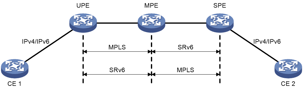
As shown in Figure 2, the MPE connects the MPLS network and SRv6 network. Configure the MPE to reoriginate routes and advertise the optimal routes.
· When the MPE receives VPNv4 or VPNv6 routes from the MPLS L3VPN network, it compares the export targets of the routes with the local import targets of the VPN instance. If they match, the MPE modifies the RD and route target attributes in the routes, assigns them SRv6 SIDs, and associate the SRv6 SID and private label of each route. Then, the MPE advertises the reoriginated routes to the SRv6 network. The supported SRv6 SIDs include End.DT4, End.DT6, End.DT46, End.DX4, and End.DX6 SIDs.
· When the MPE receives VPNv4 or VPNv6 routes from the SRv6 network, it compares the export targets of the routes with the local import targets of the VPN instance. If they match, the MPE modifies the RD and route target attributes in the routes, assign them private labels, and associate the private label and SRv6 SID of each route. Then, the MPE advertises the reoriginated routes to the MPLS L3VPN network.
When the UPE and SPE learn the reoriginated optimal routes, they forward traffic according to the route information. For example, in the L3VPN over MPLS-to-SRv6 scenario, packets are forwarded as follows:
1. When the UPE receives a packet from CE 1, it encapsulates MPLS labels to the packet and forwards the packet to the MPE.
2. When the MPE receives the packet, it removes the private label from the packet and encapsulates an SRv6 SID to the packet according to the private label-SRv6 SID mapping. Then, the MPE forwards the packet to the SPE in SRv6 BE or SRv6 TE mode.
3. When the SPE receives the packet, it decapsulates the packet based on the SRv6 SID and forwards the packet to CE 2.
Inter-AS option B VPN
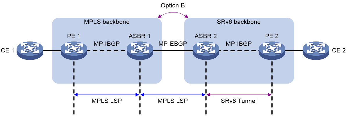
As shown in Figure 3, an MPLS network and an SRv6 network are in different ASs. For inter-AS communication, the devices must support SRv6 SID and MPLS label exchange.
Figure 3 Inter-AS option B VPN network diagram
End.T SID
The ASBR in the SRv6 network allocates End.T SIDs based on FECs and advertises the SIDs to other SRv6 nodes through an IGP. An FEC is a destination IP address/mask or destination IPv6 address/prefix length.
The function of an End.T SID is removing the outer IPv6 header and looking up the IPv6 FIB table based on the End.T SID to forward packets.
The ASBR in the SRv6 network encapsulates an End.T SID to the packets forwarded from the SRv6 network to the MPLS network.
Route advertisement
As shown in Figure 3, the route of CE 1 is advertised to CE 2 in the following process:
1. After PE 1 learns the private network route of CE 1, it assigns MPLS label L1 to the private network route. Then, PE 1 advertises the route to ASBR 1 through MP-IBGP.
2. ASBR 1 receives the VPNv4 route from PE 1 and reoriginates the route. ASBR 1 changes the next hop address of the route to its address, assign MPLS label L2 to the route, and maps MPLS label L2 and MPLS label L1. Then, the ASBR advertises the VPNv4 route to ASBR 2 through MP-EBGP.
3. ASBR 2 receives the VPNv4 route from ASBR 1 and reoriginates the route. ASBR 2 changes the next hop address of the route to its address, allocates an End.T SID to the route, and maps the End.T SID and MPLS label L2. Then, the ASBR advertises the route to PE 2 through MP-IBGP.
4. PE 2 advertises the route to CE 2.
As shown in Figure 3, the route of CE 2 is advertised to CE 1 in the following process:
5. After PE 2 learns the private network route of CE 2, it assigns an SRv6 SID to the private network route. Then, PE 2 advertises the route to ASBR 2 through MP-IBGP. The supported SRv6 SIDs include End.DT4, End.DT6, End.DT46, End.DX4, and End.DX6 SIDs.
6. ASBR 2 receives the VPNv4 route from PE 2 and reoriginates the route. ASBR 2 changes the next hop address of the route to its address, assign MPLS label L2 to the route, and maps MPLS label L2 and the SRv6 SID. Then, the ASBR advertises the VPNv4 route to ASBR 1 through MP-EBGP.
7. ASBR 1 receives the VPNv4 route from ASBR 2 and reoriginates the route. ASBR 1 changes the next hop address of the route to its address, allocates MPLS label L1 to the route, and maps MPLS label 1 and MPLS label L2. Then, the ASBR advertises the route to PE 1 through MP-IBGP.
8. PE 1 advertises the route to CE 1.
In the inter-AS option B VPN scenario, the ASBRs need to receive all inter-AS VPN routes. On the ASBRs, do not filter received VPNv4 routes based on route targets.
Traffic forwarding
As shown in Figure 3, packets are forwarded from CE 2 to CE 1 in the following process:
1. When PE 2 receives a packet from CE 2, it encapsulates an End.T SID to the packet and forwards the packet to ASBR 2.
2. When ASBR 2 receives the packet, it removes the outer IPv6 header and looks up the IPv6 FIB table based on the End.T SID. ASBR 2 finds that the out label is L2. Then, the ASBR reencapsulates MPLS label 2 to the packet and forwards the packet to ASBR 1. The packet includes only one layer of MPLS label.
3. ASBR 1 replaces MPLS label L2 with MPLS label L1 and adds the public label that identifies the public tunnel from ASBR 1 to PE 1 to the packet. Then, ASBR 1 forwards the packet to PE 1.
4. PE 1 removes the public and private labels from the packet and forwards the packet to CE 1.
Packets are forwarded from CE 1 to CE 2 in the following process:
5. When PE 1 receives a packet from CE 1, it encapsulates two layers of MPLS labels to the packet and forwards the packet to ASBR 1. The private label is L1 and the public label identifies the public tunnel from PE 1 to ASBR 1.
6. When ASBR 1 receives the packet, it removes the public label from the packet and replaces private label L1 with private label L2. Then, ASBR 1 forwards the packet to ASBR 2. The packet includes only one layer of MPLS label.
7. ASBR 2 replaces private label L2 with an SRv6 SID and forwards the packet to PE 2 according to the SRv6 SID.
8. PE 2 executes the function of the SRv6 SID and forwards the packet to CE 2.
Intercommunication between SRv6 and EVPN L3VPN networks
As shown in Figure 4, EVPN L3VPN is deployed at the sites connected by an IP L3VPN over SRv6 network. To ensure connectivity between the sites over the IP L3VPN over SRv6 network, enable intercommunication between SRv6 and EVPN L3VPN networks on the ASBRs.
Figure 4 Network diagram for intercommunication between SRv6 and EVPN L3VPN networks
When intercommunication between SRv6 and EVPN L3VPN networks is enabled on an ASBR, the ASBR processes routes as follows:
· When the ASBR receives EVPN IP prefix advertisement routes from the EVPN L3VPN network, it matches the route targets with the local import route targets. If a matching VPN instance is found, the ASBR adds the routes to the routing table of the matching VPN instance. Then, the ASBR allocates an SRv6 SID to the routes and converts the routes to VPNv4 routes based on the VPN instance configuration. Finally, the ASBR advertises the VPNv4 routes that include an SRv6 SID to the IP L3VPN over SRv6 network.
· When the ASBR receives VPNv4 routes from the IP L3VPN over SRv6 network, it matches the route targets with the local import route targets. If a matching VPN instance is found, the ASBR adds the routes to the routing table of the matching VPN instance. Then, the ASBR allocates an MPLS label to the routes and converts the routes to EVPN IP prefix advertisement routes based on the VPN instance configuration. Finally, the ASBR advertises the EVPN IP prefix advertisement routes to the EVPN L3VPN network.
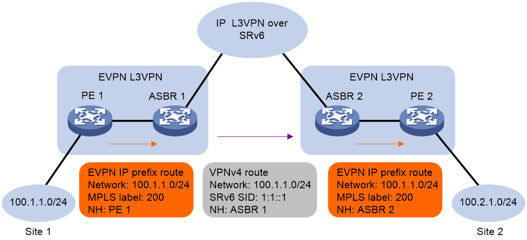
Figure 5 Packet forwarding between SRv6 and EVPN L3VPN networks
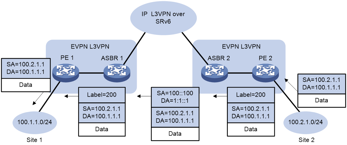
After the PEs and ASBRs finish route learning, packets from Site 2 to Site 1 are forwarded as follows:
1. When PE 2 receives packets from Site 2, it adds a private network label to the packets and forwards the packets to ASBR 2.
2. ASBR 2 performs the following operations:
a. Identifies the VPN instance of the packets based on the private network label.
b. Looks up the routing table of the VPN instance for a matching route.
c. Adds an SRv6 SID to the packets.
d. Forwards the packets to ASBR 1 in SRv6 BE or SRv6 TE mode.
3. ASBR 1 performs the following operations:
a. Identifies the VPN instance of the packets based on the SRv6 SID.
b. Removes the SRv6 encapsulation.
c. Looks up the routing table of the VPN instance.
d. Adds a private network label to the packets.
e. Forwards the packets to PE 1.
4. When PE 1 receives the packets, it performs the following operations:
a. Identifies the VPN instance of the packets based on the private network label.
b. Identifies the output interface of the packets through a lookup in the routing table of the VPN instance.
c. Removes the private network label from the packets.
d. Forwards the packets to Site 1.
SRv6 VPN cross-AS intercommunication
Transit proxies for SRv6 SIDs in cross-AS IP L3VPN over SRv6 networks (with VPN instance deployment on the border device)
In a cross-AS SRv6 VPN network where SRv6 is deployed in multiple ASs, to implement cross-AS communication, you typically need to advertise locator routes across the ASs. (For example, you can redistribute the locator routes advertised by IGP into BGP for cross-AS route advertisement.) After cross-AS advertisement for the locator routes, the PEs in different ASs can establish an SRv6 forwarding path. For security purposes, if you do not want to transmit locator routes across ASs, you can configure the ASBRs as transit proxy devices to change the SRv6 SIDs carried in routes to the SRv6 SIDs in the local VPN instances. This avoids locator route advertisement to another AS. The PEs in different ASs can establish a cross-AS SRv6 forwarding path.
Figure 6 Transit proxies for SRv6 SIDs in a cross-AS IP L3VPN over SRv6 network
As shown in Figure 6, to disable forwarding of locator routes on PE 1 to PE 2 and implement communication between site 1 and site 2, configure ASBR 2 to change the SRv6 SIDs carried in BGP routes. ASBR 2 then process BGP routes as follows:
· Upon receiving a BGP VPNv4/VPNv6 route carrying an SRv6 SID from ASBR 1, ASBR 2 adds the route to the routing table of the VPN instance matching the local RT, and delete SRv6 SID from the route. ASBR 2 then re-applies for an SRv6 SID for the BGP VPNv4/VPNv6 route in the VPN instance matching the local RT. The re-applied SRv6 SID is the same type as the original SID.
|
|
IMPORTANT: End.DX4 SIDs and End.DX6 SIDs cannot be re-applied. |
· When forwarding received BGP VPNv4/VPNv6 routes to PE 2, ASBR 2 forwards only the routes with new SRv6 SIDs.
As shown in Figure 7, after route learning, packets are forwarded from site 2 to site 1 as follows:
1. Upon receiving a packet from site 2, PE 2 looks up in the VPN routing table for route-associated SRv6 SID. Then it encapsulates the SRv6 SID (re-applied by ASBR 2 for the BGP route in the local VPN instance) for the packet, and sends the packet to ASBR 2 in SRv6 BE or SRv6 TE mode.
2. ASBR 2 determines the VPN instance of the received packet based on the SRv6 SID, removes the SRv6 encapsulation, and looks up in the routing table of the associated VPN instance. After obtaining the route-associated SRv6 SID, it encapsulates the SRv6 SID (original SRv6 SID advertised by PE 1) for the packet, and sends the packet to PE 1 in SRv6 BE or SRv6 TE mode.
3. Upon receiving the packet, PE 1 determines the VPN instance of the received packet based on the SRv6 SID, removes the SRv6 encapsulation, looks up in the routing table of the associated VPN instance, and forwards the packet to site 1.
The packet forwarding procedure requires the ASBR to obtain the PE-advertised locator route in the peer AS. The PE does not need to obtain the PE-advertised locator route in the peer AS. It only requires the ASBR-advertised locator route in the local AS. The transit proxy behavior of the ASBR resolves the communication issues between SRv6 sites when locator routes are not advertised across ASs.
Cross-AS Option B (without requiring VPN instance deployment for the border device)
The biggest challenge in achieving inter-AS intercommunication in SRv6 networks is establishing inter-AS SRv6 forwarding paths. A currently feasible method is to advertise SRv6 SID information of intermediate nodes to another AS. Different ASs typically belong to separate ISPs, who do not want leakage of too much node information to other networks.
To address this issue, H3C introduced the SRv6 VPN Option B cross-AS solution. The solution does not require the advertisement of locator routes in the AS to another AS, or the deployment of VPN instances on the ASBR. By enabling SRv6 network cross-AS intercommunication on the ASBRs, the solution can enable the following intercommunications between private network users in different ASs:
· Intercommunication between an IP L3VPN over SRv6 network and an EVPN L3VPN over SRv6 network.
· Intercommunication between IP L3VPN over SRv6 networks.
· Intercommunication between EVPN L3VPN networks.
This chapter uses the intercommunication between IP L3VPN over SRv6 networks as an example. The mechanisms for the other types of network intercommunications are almost the same, except for the following differences.
· Intercommunication between an IP L3VPN over SRv6 network and an EVPN L3VPN over SRv6 network requires establishing BGP VPNv4/VPNv6 sessions between the PE and ASBR in the IP L3VPN over SRv6 network, and establishing BGP EVPN sessions between the PE and ASBR in the EVPN L3VPN over SRv6 network. In the IP L3VPN over SRv6 network, private network routes are transmitted through BGP VPNv4/VPNv6 routes. In the EVPN L3VPN over SRv6 network, private network routes are transmitted through IP prefix routes. The ASBR must translate between BGP VPNv4/VPNv6 and IP prefix routes through route reorigination.
· Intercommunication between IP L3VPN over SRv6 networks requires establishing BGP VPNv4/VPNv6 sessions among all backbone devices, allowing private network routes to be transmitted only through BGP VPNv4/VPNv6 routes.
· Intercommunication between EVPN L3VPN over SRv6 networks requires establishing BGP EVPN sessions among all backbone devices, and transmitting private network routes through IP prefix routes.
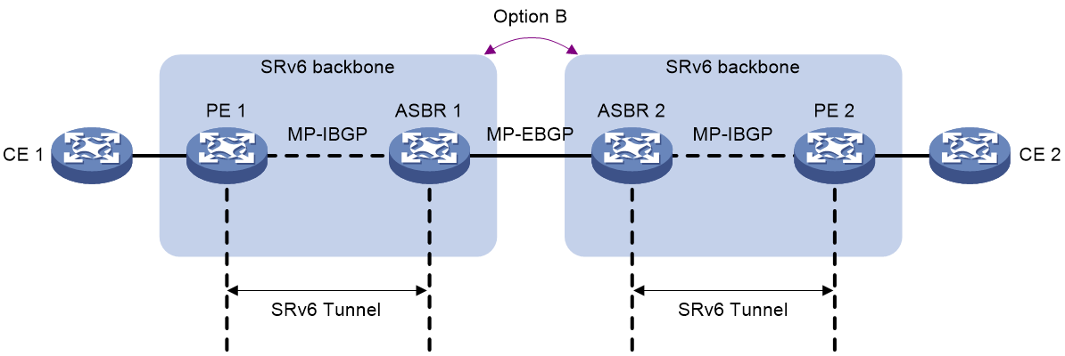
Networking model
In the network as shown in Figure 8, each AS is deployed with an IP L3VPN over SRv6 or EVPN L3VPN over SRv6 network. The ASBRs between two ASs establish EBGP sessions in BGP VPNv4/VPNv6 or BGP EVPN address family to exchange private network routes.
Before implementing private network user intercommunication between CE 1 and CE 2, you must first advertise the private network routes between them. Upon receiving a private network packet, the CE sends it to the PE, which then forwards it to the remote PE through SRv6. The remote PE decapsulates the SRv6 packet and forwards it to the remote CE.
Figure 8 SRv6 VPN Option B cross-AS networking diagram
End.R SID
H3C introduced a new type of private SRv6 SID—End.R SID—to implement SRv6 VPN Option B cross-AS functionality. The ASBR reallocates End.R SIDs for BGP VPNv4/VPNv6 and BGP EVPN routes carrying SIDs. It also advertise locator routes corresponding to the End.R SIDs to the peer ASBR or the PE within the local AS. The forwarding action of an End.R SID is removing the outer IPv6 header, searching the IPv6 FIB table based on the End.R SID, and re-encapsulates packets with a new outer IPv6 header for forwarding based on the search result.
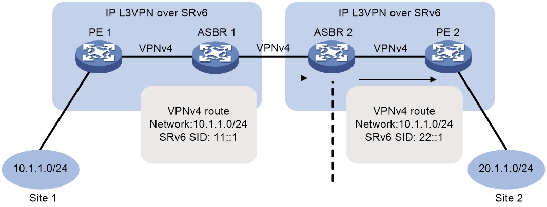
Route advertisement
Figure 9 Route advertisement in the SRv6 VPN Option B cross-AS network
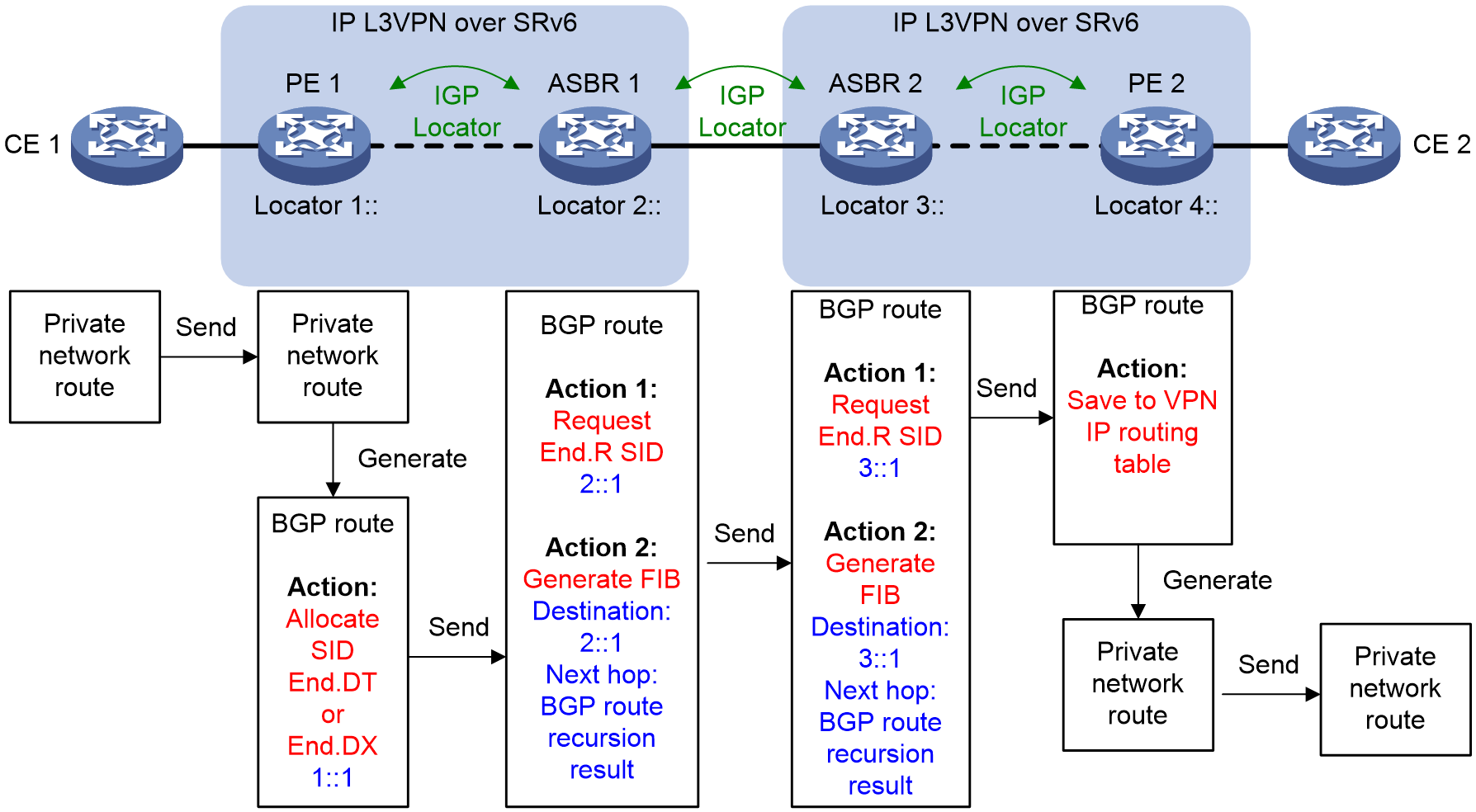
As shown in Figure 9, the private network route of CE 1 is advertised to CE 2 in the following process:
1. IGP is used to advertise locator routes between PE 1 and ASBR 1, between ASBR 1 and ASBR 2, and between ASBR 2 and PE 2.
2. After learning private network routes from CE 1, PE 1 redistributes them into BGP, and reoriginates BGP VPNv4/VPNv6 routes. It then assigns End.DT4 SID, End.DT6 SID, End.DT46 SID, End.DX4 SID, or End.DX6 SID to the reoriginated BGP routes based on their VPN instance or next hop.
3. PE 1 sends the BGP VPNv4/VPNv6 routes to ASBR 1 through the IBGP session.
4. With SRv6 network cross-AS intercommunication enabled on ASBR 1, if ASBR 1 receives a BGP VPNv4/VPNv6 route carrying an SID, it performs the following actions:
a. Requests End.R SID 2::1 for the BGP route. The requested End.R SID is from the locator segment 2:: specified for the BGP VPNv4/VPNv6 address family.
b. Generates an IPv6 FIB entry, with destination network address of 2::1 corresponding to the End.R SID, and the next hop as that obtained through recursive lookup in the BGP VPNv4/VPNv6 address family. The ASBR then associates this entry with the source SRv6 SID 1::1 carried in the BGP route. For example, for a recursive BGP route in SRv6 BE mode, the next hop is the IPv6 address destined for SRv6 SID 1::1 in the SRv6 forwarding table. For a recursive BGP route in SRv6 TE mode, the next hop is the SRv6 TE policy.
5. ASBR 1 replaces the SID carried in the BGP VPNv4/VPNv6 route with the requested End.R SID, and sends the BGP route with the replaced SID to ASBR 2 through the EBGP session.
6. With SRv6 network cross-AS intercommunication configured, ASBR 2 performs the following actions upon receiving a BGP VPNv4/VPNv6 route carrying an SID:
¡ Requests End.R SID 3::1 for the BGP route again. The requested End.R SID is from the locator segment 3:: specified for the BGP VPNv4/VPNv6 or BGP EVPN address family.
¡ Generates an IPv6 FIB entry, with destination network address of 3::1 corresponding to the End.R SID, and the next hop as that obtained through recursive lookup in the BGP VPNv4/VPNv6 or BGP EVPN address family. The ASBR then associates this entry with the source SRv6 SID 2::1 carried in the BGP route. For example, for a recursive BGP route in SRv6 BE mode, the next hop is the IPv6 address destined for SRv6 SID 2::1 in the SRv6 forwarding table. For a recursive BGP route in SRv6 TE mode, the next hop is the SRv6 TE policy.
7. ASBR 2 replaces the SID carried in the BGP VPNv4/VPNv6 route with the requested End.R SID, and sends the BGP route with the replaced SID to PE 2 through the IBGP session.
8. Upon receiving the VPNv4/VPNv6 routes from ASBR 2, PE 2 redistributes them to the routing table of the VPN instance based on the RTs, generates private network routes, and advertises the routes to CE 2.
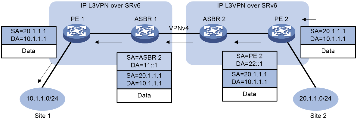
Packet forwarding in SRv6 BE mode
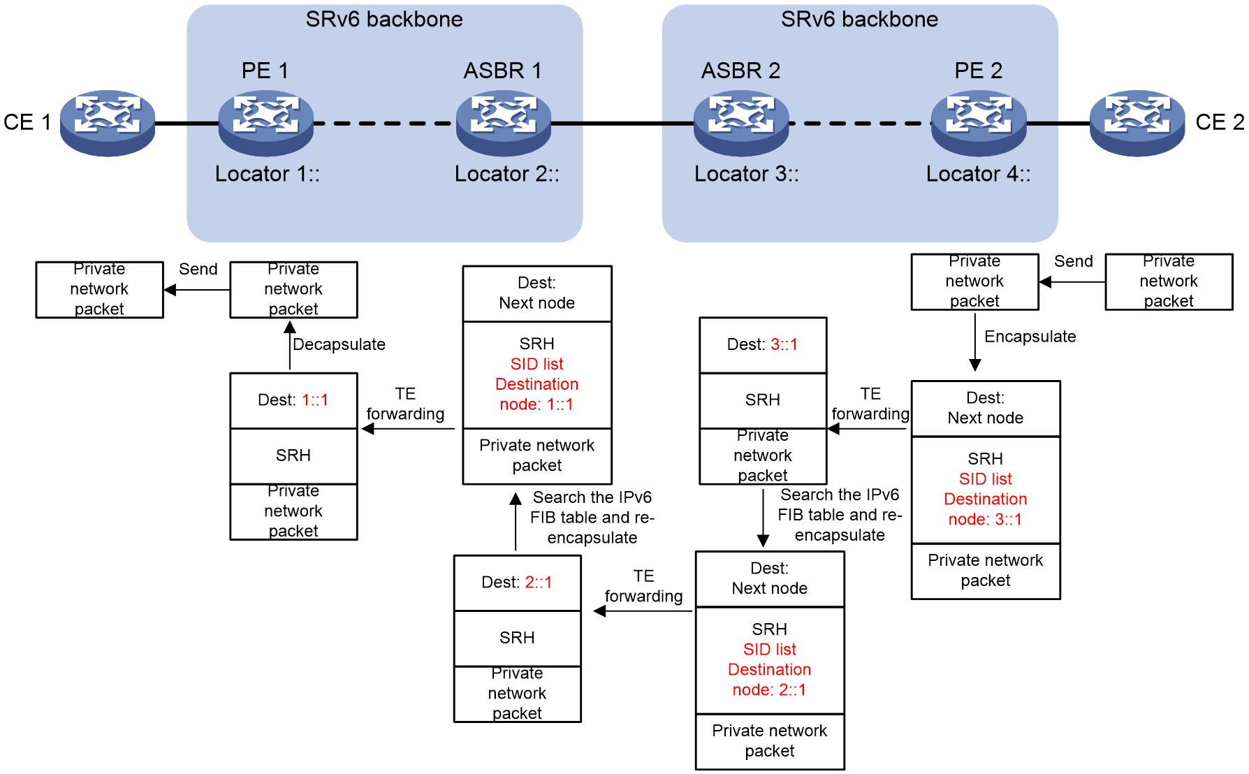
Figure 10 Packet forwarding in the SRv6 VPN Option B cross-AS network (SRv6 BE mode)

As shown in Figure 10, private network packets are forwarded from CE 2 to CE 1 in SRv6 BE mode in the following process:
1. Upon receiving the private network packet from the interface bound to a VPN instance, PE 2 searches the routing table of the VPN instance for a route matching the destination IP address, and obtains the associated End.R SID. Based on the obtained End.R SID 3::1, PE 2 encapsulates an IPv6 header for the packet, and uses End.R SID 3::1 as the destination address in the IPv6 header.
2. PE 2 searches the IPv6 routing table based on destination address 3::1, and forwards the packet to ASBR 2 through the optimal locator route.
3. Upon receiving a packet with an encapsulated IPv6 header, ASBR 2 finds that 3::1 is a local End.R SID. It then removes the IPv6 header and searches the IPv6 FIB table for destination address 3::1. Upon finding an IPv6 FIB entry with destination address 3::1, ASBR 2 performs SRv6 forwarding for the packet based on the entry. That is, it re-encapsulates a new outer IPv6 header for the packet, where the destination IPv6 address is End.R SID 2::1 associated with the IPv6 FIB entry.
4. ASBR 2 searches the IPv6 routing table based on destination address 2::1, and forwards the packet to ASBR 1 through the locator route.
5. Upon receiving the packet with an encapsulated IPv6 header, ASBR 1 finds that 2::1 is a local End.R SID. It then removes the IPv6 header and searches the IPv6 FIB table for destination address 2::1. Upon finding an IPv6 FIB entry with destination address 2::1, ASBR 1 performs SRv6 forwarding for the packet based on the entry. That is, it re-encapsulates a new outer IPv6 header for the packet, where the destination IPv6 address is SRv6 SID 1::1 associated with the IPv6 FIB entry.
6. ASBR 1 searches the IPv6 routing table based on destination address 1::1, and forwards the packet to PE 1 through the locator route.
7. Upon receiving the packet, PE 1 removes the IPv6 header, and forwards the packet by searching the VPN instance routing table or through the bound next hop output interface based on the SID type corresponding to the destination address 1::1.
Packet forwarding in SRv6 TE mode
Figure 11 Packet forwarding in the SRv6 VPN Option B cross-AS network (SRv6 TE mode)
|
|
NOTE: The SRv6 TE policy configuration might vary on different nodes. This example does not describe detailed SRv6 TE policy information for each node. It provides only the approximate information of recursion of BGP VPNv4 routes to the SRv6 TE policy. · PE 2: The destination node for the SRv6 TE policy is End.R SID 3::1 of ASBR 2. The planned SID list can include any SID. · ASBR 2: The destination node for the SRv6 TE policy is End.R SID 2::1 of ASBR 1. The planned SID list can include any SID. · ASBR 1: The destination node for the SRv6 TE policy is End.DT4 1::1 of PE 1. The planned SID list can include any SID. |
As shown in Figure 11, private network packets are forwarded from CE 2 to CE 1 in SRv6 TE mode in the following process:
1. Upon receiving the private network packet from the interface bound to a VPN instance, PE 2 searches the routing table of the VPN instance, and obtains a route redistributed from BGP and the route-associated End.R SID. Because the BGP route that forwards the private network packet is steered in SRv6 TE mode, PE 2 adds an SRH and IPv6 header, and then forwards the packet through the SRv6 TE policy. The destination node of the SID list in the SRH is End.R SID 3::1.
2. When ASBR 2 receives the packet, it removes the SRH and the outer IPv6 header because SL = 0 in the SRH. Then, it searches the IPv6 FIB table for destination address 3::1, and obtains the next hop for destination address 3::1 as the SRv6 TE policy. Then, ASBR 2 adds the SRH and IPv6 header to the packet again, and forwards the packet through the SRv6 TE policy. The destination node in the SID list of the SRH is End.R SID 2::1.
3. When ASBR 1 receives the packet, it removes the SRH and the outer IPv6 header because SL = 0 in the SRH. Then, it searches the IPv6 FIB table for destination address 2::1, and obtains the next hop for destination address 2::1 as the SRv6 TE policy. Then, ASBR 1 adds the SRH and IPv6 header to the packet again, and forwards the packet through the SRv6 TE policy. The destination node in the SID list of the SRH is SRv6 SID 1::1.
4. Upon receiving the packet, PE 1 removes the SRH and the outer IPv6 header because SL = 0 in the SRH, in order to decapsulate the packet's IPv6 header. It then forwards the packet by searching the VPN instance routing table or through the bound next hop output interface based on the SID type corresponding to the destination address 1::1.
IP L3VPN over SRv6 FRR
|
|
IMPORTANT: IP L3VPN over SRv6 FRR is supported only when the customer sites belong to VPNs. |
IP L3VPN over SRv6 Fast Reroute (FRR) is applicable to a dualhomed scenario, as shown in Figure 12. By using static BFD to detect the primary link, FRR enables a PE to use the backup link when the primary link fails. The PE then selects a new optimal route, and uses the new optimal route to forward traffic.
IP L3VPN over SRv6 supports VPNv4 route backup for a VPNv4 route and VPNv6 route backup for a VPNv6 route.
Figure 12 Network diagram of VPNv4 route backup for a VPNv4 route
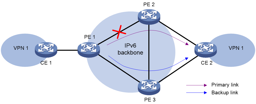
IPv4 L3VPN over SRv6 and IPv6 L3VPN over SRv6 use the same FRR mechanism. This section uses VPNv4 route backup for a VPNv4 route as an example to illustrate the mechanism.
As shown in Figure 12, configure FRR on the ingress node PE 1, and specify the backup next hop for VPN 1 as PE 3. When PE 1 receives a VPNv4 route to CE 2 from both PE 2 and PE 3, it uses the route from PE 2 as the primary link, and the route from PE 3 as the backup link.
Configure static BFD for public tunnels on PE 1 to detect the connectivity of the public tunnel from PE 1 to PE 2. When the tunnel PE 1—PE 2 operates correctly, traffic from CE 1 to CE 2 goes through the path CE 1—PE 1—PE 2—CE 2. When the tunnel fails, the traffic goes through the path CE 1—PE 1—PE 3—CE 2.
In this scenario, PE 1 is responsible for primary link detection and traffic switchover.
For more information about static BFD, see BFD configuration in High Availability Configuration Guide.
Restrictions and guidelines: IP L3VPN over SRv6 configuration
In an IP L3VPN over SRv6 network, you cannot configure the MPLS DiffServ mode. For more information about the MPLS DiffServ mode, see MPLS QoS configuration in ACL and QoS Configuration Guide.
In an IP L3VPN over SRv6 network, route output interfaces do not support load balancing between GRE tunnel interfaces and common physical interfaces. Avoid such configurations to prevent uneven load balancing.
IP L3VPN over SRv6 tasks at a glance
To configure IP L3VPN over SRv6, perform the following tasks:
1. Configuring a VPN instance and associating interfaces connected to CEs with the VPN instance
Perform this task on PEs. For more information, see MPLS L3VPN in MPLS Configuration Guide.
2. Configuring route exchange between a PE and a CE
Configure an IPv4 routing protocol (static routing, RIP, OSPF, IS-IS, EBGP, or IBGP) or an IPv6 routing protocol (IPv6 static routing, RIPng, OSPFv3, IPv6 IS-IS, EBGP, or IBGP) to exchange routes between a PE and a CE
On the CE, configure an IPv4 or IPv6 routing protocol to advertise routes of the local site to the PE. On the PE, associate the routing protocol with the VPN instance. For more information about routing protocol configurations, see Layer 3—IP Routing Configuration Guide.
3. Configuring route exchange between PEs
Perform this task to manually configure an End.DT4, End.DT6, End.DT46, End.DX4, or End.DX6 SID.
b. Applying a locator to a BGP VPN instance
BGP can advertise SRv6 SIDs through BGP routes only after you apply a locator to BGP.
c. Configuring PEs to exchange BGP VPNv4 or VPNv6 routes
d. Configuring IPv6 peers to exchange SRv6 SIDs
This feature enables PEs to exchange End.DT4, End.DT6, End.DT46, End.DX4, or End.DX6 SIDs through BGP VPNv4 or VPNv6 routes.
e. (Optional.) Configuring next hop-based dynamic End.DX4 or End.DX6 SID allocation for BGP private network routes
This feature enables a PE to dynamically allocate End.DX4 or End.DX6 SIDs to BGP routes based on the route next hops.
f. (Optional.) Configuring BGP VPNv4 or VPNv6 routes
4. Configuring the route recursion mode
5. Specifying a source address for the outer IPv6 header of SRv6-encapsulated packets
This feature specifies the source address of the outer IPv6 header for SRv6 packets that are delivered between two sites over the backbone network.
6. (Optional.) Enabling SRv6 VPN compatibility for a peer or peer group
7. (Optional.) Configuring intercommunication for SRv6 and MPLS networks
¡ Configuring optimal route reorigination and advertisement
¡ Modifying BGP VPNv4 or VPNv6 routes
¡ Configuring inter-AS option B VPN
8. (Optional.) Enabling intercommunication between SRv6 and EVPN L3VPN networks
9. (Optional.) Configuring SRv6 VPN cross-AS intercommunication
¡ Configuring transit proxies for SRv6 SIDs in cross-AS IP L3VPN over SRv6 networks
¡ Configuring SRv6 VPN Option B cross-AS intercommunication
10. (Optional.) Configuring IP L3VPN over SRv6 FRR
11. (Optional.) Configuring SBFD for SRv6 locators
12. (Optional.) Configuring a TTL processing mode for tunnels associated with a VPN instance
Configuring an SRv6 SID
Configuring a common SRv6 SID
Restrictions and guidelines
If PEs advertise BGP VPNv4 or VPNv6 routes to each other, you must specify a VPN instance when configuring an opcode.
Procedure
1. Enter system view.
system-view
2. Enable SRv6 and enter SRv6 view.
segment-routing ipv6
3. Configure a locator and enter SRv6 locator view.
locator locator-name [ ipv6-prefix ipv6-address prefix-length [ args args-length | static static-length ] * ]
4. Configure an opcode. Perform one of the following tasks:
¡ Configure an End.DT4 SID.
opcode { opcode | hex hex-opcode } end-dt4 [ vpn-instance vpn-instance-name ]
The specified VPN instance must exist. An End.DT4 SID cannot be configured in different VPN instances.
¡ Configure an End.DT6 SID.
opcode { opcode | hex hex-opcode } end-dt6 [ vpn-instance vpn-instance-name ]
The specified VPN instance must exist. An End.DT6 SID cannot be configured in different VPN instances.
¡ Configure an End.DT46 SID.
opcode { opcode | hex hex-opcode } end-dt46 [ vpn-instance vpn-instance-name ]
The specified VPN instance must exist. An End.DT46 SID cannot be configured in different VPN instances.
¡ Configure an End.DX4 SID.
opcode { opcode | hex hex-opcode } end-dx4 interface interface-type interface-number nexthop nexthop-ipv4-address [ vpn-instance vpn-instance-name ]
The specified VPN instance must exist. An End.DX4 SID cannot be configured with different output interfaces or next hops.
¡ Configure an End.DX6 SID.
opcode { opcode | hex hex-opcode } end-dx6 interface interface-type interface-number nexthop nexthop-ipv6-address [ vpn-instance vpn-instance-name ]
The specified VPN instance must exist. An End.DX6 SID cannot be configured with different output interfaces or next hops.
Configuring SRv6 SIDs for a COC16-type locator
About this task
A locator specified with the compress-16 keyword is a COC16-type locator. Such locators are used for assigning SIDs in the 16-bit G-SRv6 scenario. COC16 locators can be divided into the following types:
· Default-mode locator—A locator without the next keyword specified. You can assign a G-SID with the COC flavor, NEXT flavor, and COC&NEXT flavor, or a common SID without COC or NEXT flavors. This locator applies to all 16-bit compression G-SRv6 encapsulation solutions.
· Next-mode locator—A locator with the next keyword specified. Use this feature to assign a G-SID that carries only the NEXT flavor, or a common SID that does not carry the COC or NEXT flavor. When the H3C device interoperates with a third-party device that supports the 16-bit compression G-SRv6 encapsulation solution with only the move action, configure a Next-mode locator to allocate SIDs.
· Wlib-mode locator—A locator with the next-wlib keyword specified. It can allocate G-SIDs with the NEXT flavor from the extended W-LIB space or from the compressed function. In the current software version, the Wlib-mode locator typically uses the W-LIB space to allocate SIDs for VPN services.
Restrictions and guidelines
For a Wlib-mode locator, to allocate an opcode from the W-LIB space, follow these guidelines when you execute the opcode command to configure VPN-related SIDs such as End.DT4 SIDs: 1. First, make sure the specified opcode or hexadecimal hex-opcode includes one of the values in the range of wlib-static-value to wlib-start-value+7 specified in the locator command. 2. Then, specify the opcode in the W-LIB space. As a best practice, use the hexadecimal hex-opcode argument to configure the opcode. For example, if the value for the wlib-start-value argument is 0xFFF3 and the value for the wlib-static-value argument is 0xFFF7, you must first specify a value between FFF7 and FFFA for the hex-opcode argument, and then then assign an opcode in the W-LIB space.
Configuring SRv6 SIDs for a default-mode locator
1. Enter system view.
system-view
2. Enable SRv6 and enter SRv6 view.
segment-routing ipv6
3. Enable SRv6 compression.
srv6 compress enable
By default, SRv6 compression is disabled.
4. Configure a default-mode locator and enter SRv6 locator view.
locator locator-name [ ipv6-prefix ipv6-address prefix-length compress-16 [ non-compress-static non-compress-static-length ] [ args args-length | static static-length ] * ]
5. Configure an opcode to statically specify an SRv6 SID and the SID-associated function and flavor.
¡ Assign a common SRv6 SID that does not carry the COC or NEXT flavor from the non-compressed Function portion. (Details not shown.)
¡ Assign an SRv6 SID that carries the COC or NEXT flavor from the compressed Function portion.
opcode { opcode | hex hex-opcode } end-dt4 [ vpn-instance vpn-instance-name [ l3vpn-evpn ] ] compress { next | coc-next }
Configure an End.DT4 SID.
opcode { opcode | hex hex-opcode } end-dt46 [ vpn-instance vpn-instance-name [ l3vpn-evpn ] ] compress { next | coc-next }
Configure an End.DT46 SID.
opcode { opcode | hex hex-opcode } end-dt6 [ vpn-instance vpn-instance-name [ l3vpn-evpn ] ] compress { next | coc-next }
Configure an End.DT6 SID.
opcode { opcode | hex hex-opcode } end-dx4 interface interface-type interface-number nexthop nexthop-ipv4-address [ vpn-instance vpn-instance-name ] compress { next | coc-next }
Configure an End.DX4 SID.
opcode { opcode | hex hex-opcode } end-dx6 interface interface-type interface-number nexthop nexthop-ipv4-address [ vpn-instance vpn-instance-name ] compress { next | coc-next }
Configure an End.DX6 SID.
Configuring SRv6 SIDs for a Next-mode locator
1. Enter system view.
system-view
2. Enable SRv6 and enter SRv6 view.
segment-routing ipv6
3. Enable SRv6 compression.
srv6 compress enable
By default, SRv6 compression is disabled.
4. Configure a Next-mode locator and enter SRv6 locator view.
locator locator-name [ ipv6-prefix ipv6-address prefix-length compress-16 next [ non-compress-static non-compress-static-length ] [ args args-length | static static-length ] * ]
5. Configure an opcode to statically specify an SRv6 SID and the SID-associated function and flavor.
¡ Assign a common SRv6 SID that does not carry the COC or NEXT flavor from the non-compressed Function portion. (Details not shown.)
¡ Assign an SRv6 SID that carries the NEXT flavor from the compressed Function portion.
opcode { opcode | hex hex-opcode } end-dt4 [ vpn-instance vpn-instance-name [ l3vpn-evpn ] ] compress next
Configure an End.DT4 SID.
opcode { opcode | hex hex-opcode } end-dt46 [ vpn-instance vpn-instance-name [ l3vpn-evpn ] ] compress next
Configure an End.DT46 SID.
opcode { opcode | hex hex-opcode } end-dt6 [ vpn-instance vpn-instance-name [ l3vpn-evpn ] ] compress next
Configure an End.DT6 SID.
opcode { opcode | hex hex-opcode } end-dx4 interface interface-type interface-number nexthop nexthop-ipv4-address [ vpn-instance vpn-instance-name ] compress next
Configure an End.DX4 SID.
opcode { opcode | hex hex-opcode } end-dx6 interface interface-type interface-number nexthop nexthop-ipv4-address [ vpn-instance vpn-instance-name ] compress next
Configure an End.DX6 SID.
Configuring SRv6 SIDs for a Wlib-mode locator
1. Enter system view.
system-view
2. Enable SRv6 and enter SRv6 view.
segment-routing ipv6
3. Enable SRv6 compression.
srv6 compress enable
By default, SRv6 compression is disabled.
4. Configure a Wlib-mode locator and enter SRv6 locator view.
locator locator-name [ ipv6-prefix ipv6-address prefix-length compress-16 next-wlib [ wlib-start wlib-start-value ] [ wlib-static-start wlib-static-value ] [ args args-length | static static-length ] * ]
5. Configure an opcode to statically specify an SRv6 SID and the SID-associated function and flavor.
¡ Assign an SRv6 SID that carries the NEXT flavor from the extended W-LIB space.
opcode { opcode | hex hex-opcode } end-dt4 [ vpn-instance vpn-instance-name [ l3vpn-evpn ] ] compress next
Configure an End.DT4 SID.
opcode { opcode | hex hex-opcode } end-dt46 [ vpn-instance vpn-instance-name [ l3vpn-evpn ] ] compress next
Configure an End.DT46 SID.
opcode { opcode | hex hex-opcode } end-dt6 [ vpn-instance vpn-instance-name [ l3vpn-evpn ] ] compress next
Configure an End.DT6 SID.
opcode { opcode | hex hex-opcode } end-dx4 interface interface-type interface-number nexthop nexthop-ipv4-address [ vpn-instance vpn-instance-name ] compress next
Configure an End.DX4 SID.
opcode { opcode | hex hex-opcode } end-dx6 interface interface-type interface-number nexthop nexthop-ipv4-address [ vpn-instance vpn-instance-name ] compress next
Configure an End.DX6 SID.
Applying a locator to a BGP VPN instance
About this task
This feature is applicable to an IP L3VPN over SRv6 network with VPN sites. Use this feature in BGP-VPN IPv4 or IPv6 unicast address family view of a VPN instance to enable the PE to apply for SRv6 SIDs for the private network routes of the VPN instance. In addition, this feature enables the PE to carry the Prefix SID attribute in BGP routes of the specified address family for advertising SIDs of the locator.
Use this feature if the device will use End.DT4, End.DT6, End.DT46, End.DX4, or End.DX6 SIDs to deliver VPN traffic across sites.
In the 16-bit compression G-SRv6 scenario, use this feature to specify a locator of the COC16 type and specify the compress-16 keyword. This allows allocation of VPN SIDs such as End.DT4, End.DT6, End.DT46, End.DX4, and End.DX6 SIDs from that locator, which carry the COC&NEXT or NEXT flavor. When encapsulating SRv6 packets, the source node can compress the previous VPN SIDs to 16 bits before encapsulating them into the SRv6 packets, reducing the length of the SRv6 packet header. Upon receiving a 16-bit compressed G-SRv6 packet, the PE acting as the endpoint node of the SRv6 tunnel performs the replace or move action based on the COC or NEXT flavor carried by the VPN SID. For more information about the replace and move actions, see SRv6 configuration in Segment Routing Configuration Guide.
Restrictions and guidelines
Before you perform this task, make sure the following conditions are met:
· The specified locator must already exist.
· The VPN instance of the specified locator must be the same as the VPN instance of the private network. To specify a VPN instance for a locator, use the opcode end-dt4, opcode end-dt6, opcode end-dt46, opcode end-dx4, or opcode end-dx6 command in SRv6 locator view.
If you execute the segment-routing ipv6 locator command and specify the compress-16 keyword, you must specify the COC16-type locator for this command. Without this configuration, SID allocation from the locator might not be as expected.
· If you execute the segment-routing ipv6 locator command to specify a non-COC16-type locator, specifying the compress-16 keyword will not take effect. That is, you cannot allocate SIDs from that locator.
· If you execute the segment-routing ipv6 locator command to specify a COC16-type locator in default or Next mode, and do not specify the compress-16 keyword, common SIDs can be allocated from the non-compressed Function portion of that locator. Common SIDs do not carry the COC or NEXT flavor and cannot be encapsulated by using16-bit compression.
· If you execute the segment-routing ipv6 locator command to specify a COC16-type locator in Wlib mode, and do not specify the compress-16 keyword, SIDs cannot be allocated from that locator.
If you execute the segment-routing ipv6 locator command and specify the compress-16 keyword, you can also execute the segment-routing ipv6 apply-sid compress command to configure the flavor for the SIDs allocated from the locator.
Procedure
1. Enter system view.
system-view
2. Enter BGP instance view.
bgp as-number [ instance instance-name ]
3. Enter BGP-VPN instance view.
ip vpn-instance vpn-instance-name
4. Enter BGP-VPN IPv4 unicast address family view or BGP-VPN IPv6 unicast address family view.
¡ Enter BGP-VPN IPv4 unicast address family view.
address-family ipv4 [ unicast ]
¡ Enter BGP-VPN IPv6 unicast address family view.
address-family ipv6 [ unicast ]
5. Apply a locator to the BGP VPN instance.
segment-routing ipv6 locator locator-name [ auto-sid-disable | auto-sid-dt46 ] [ compress-16 ]
By default, no locator is applied to a BGP VPN instance.
6. (Optional) Configure the flavor carried in the SIDs dynamically allocated from the COC16-type locator specified for BGP.
segment-routing ipv6 apply-sid compress { coc-next | next [ wlib ] } [ end-dt46 ]
By default, for a COC16-type locator in default mode, SRv6 SIDs are allocated with the COC and NEXT flavors from the compressed Function portion. For a COC16-type locator in Next mode, SRv6 SIDs are allocated with the NEXT flavor from the compressed Function portion. For a COC16-type locator in Wlib mode, SRv6 SIDs are allocated with the NEXT flavor from the W-LIB space.
Configuring PEs to exchange BGP VPNv4 or VPNv6 routes
Restrictions and guidelines
For more information about the commands in this section, see BGP in Layer 3—IP Routing Command Reference.
To ensure optimal route selection and SRv6 tunnel traffic forwarding, make sure a pair of PEs are not both IPv4 and IPv6 peers to each other.
Procedure
1. Enter system view.
system-view
2. Enter BGP instance view.
bgp as-number [ instance instance-name ]
3. Specify a remote PE as an IPv6 peer.
peer { group-name | ipv6-address [ prefix-length ] } as-number as-number
4. Specify a source interface (IPv6 address) for establishing TCP connections to an IPv6 peer or peer group.
peer { group-name | ipv6-address [ prefix-length ] } connect-interface interface-type interface-number
By default, BGP uses the output interface in the optimal route destined for a BGP peer or peer group as the source interface for establishing TCP connections.
5. Create the BGP VPNv4 or VPNv6 address family and enter its view.
¡ Create the BGP VPNv4 address family and enter its view.
address-family vpnv4
¡ Create the BGP VPNv6 address family and enter its view.
address-family vpnv6
6. Enable BGP to exchange VPNv4 or VPNv6 routing information with an IPv6 peer or peer group.
peer { group-name | ipv6-address [ prefix-length ] } enable
By default, BGP cannot exchange VPNv4 or VPNv6 routing information with an IPv6 peer or peer group.
Configuring IPv6 peers to exchange SRv6 SIDs
About this task
Perform this task to configure IPv6 peers to exchange SRv6 SID information through BGP VPNv4, VPNv6, IPv4 unicast, or IPv6 unicast routes.
Procedure
1. Enter system view.
system-view
2. Enter BGP instance view.
bgp as-number [ instance instance-name ]
3. Enter BGP VPNv4 address family view or BGP VPNv6 address family view.
¡ Enter BGP VPNv4 address family view.
address-family vpnv4
¡ Enter BGP VPNv6 address family view.
address-family vpnv6
4. Enable BGP to exchange SRv6 SID information with an IPv6 peer or peer group.
peer { group-name | ipv6-address [ prefix-length ] } prefix-sid
By default, BGP cannot exchange SRv6 SID information with an IPv6 peer or peer group.
Configuring next hop-based dynamic End.DX4 or End.DX6 SID allocation for BGP private network routes
About this task
This task is applicable to an IP L3VPN over SRv6 network. Perform this task to forward an SRv6 decapsulated VPN packet to the next hop without looking up the routing table of the matching VPN instance.
By default, a PE allocates the same SID to all BGP private network routes in a VPN instance. When the PE removes the SRv6 encapsulation from a received packet, it looks up the routing table of the VPN instance based on the SID for an optimal route. Then, the PE forwards the packet to a CE. To forward the packet to the next hop without looking up the routing table, perform this task.
This task dynamically allocates End.DX4 or End.DX6 SIDs to specific next hops or all next hops of the BGP private network routes in a VPN instance based on the next hop addresses. When forwarding a packet, the PE searches for the output interface and next hop based on the End.DX4 or End.DX6 SID of the packet. Then, the PE directly forwards the packet out of the output interface to the next hop.
Restrictions and guidelines
This feature does not allocate End.DX4 or End.DX6 SIDs to direct routes.
Prerequisites
In BGP-VPN IPv4 or IPv6 unicast address family view, execute the segment-routing ipv6 locator command to apply a locator to the view. This ensures successful dynamic End.DX4 or End.DX6 SID allocation.
Procedure
1. Enter system view.
system-view
2. Enter BGP instance view.
bgp as-number [ instance instance-name ]
3. Enter BGP-VPN instance view.
ip vpn-instance vpn-instance-name
4. Enter BGP-VPN IPv4 unicast address family view or BGP-VPN IPv6 unicast address family view.
¡ Enter BGP-VPN IPv4 unicast address family view.
address-family ipv4 [ unicast ]
¡ Enter BGP-VPN IPv6 unicast address family view.
address-family ipv6 [ unicast ]
5. Configure next hop-based dynamic End.DX4 or End.DX6 SID allocation for BGP private network routes. Choose one of the following tasks:
¡ Automatically allocate an End.DX4 or End.DX6 SID to each next hop of BGP private network routes.
segment-routing ipv6 apply-sid all-nexthop
¡ Execute the following commands in sequence to automatically allocate an End.DX4 or End.DX6 SID to the specified next hop of BGP private network routes:
segment-routing ipv6 apply-sid specify-nexthop
nexthop nexthop-address interface interface-type interface-number
By default, VPN instance-based SID allocation is used for private network routes.
Configuring BGP VPNv4 or VPNv6 routes
Restrictions and guidelines for BGP VPNv4 or VPNv6 route configuration
For more information about the commands in this section, see BGP in Layer 3—IP Routing Command Reference.
Controlling BGP VPNv4 or VPNv6 route advertisement and reception
1. Enter system view.
system-view
2. Enter BGP instance view.
bgp as-number [ instance instance-name ]
3. Enter BGP VPNv4 address family view or BGP VPNv6 address family view.
¡ Enter BGP VPNv4 address family view.
address-family vpnv4
¡ Enter BGP VPNv6 address family view.
address-family vpnv6
4. Set the maximum number of routes that BGP can receive from a peer or peer group.
peer { group-name | ipv6-address [ prefix-length ] } route-limit prefix-number [ { alert-only | discard | reconnect reconnect-time } | percentage-value ] *
By default, the number of routes that BGP can receive from a peer or peer group is not limited.
5. Save all route updates from a peer or peer group.
peer { group-name | ipv6-address [ prefix-length ] } keep-all-routes
By default, route updates from peers and peer groups are not saved.
Setting a preferred value for received BGP VPNv4 or VPNv6 routes
1. Enter system view.
system-view
2. Enter BGP instance view.
bgp as-number [ instance instance-name ]
3. Enter BGP VPNv4 address family view or BGP VPNv6 address family view.
¡ Enter BGP VPNv4 address family view.
address-family vpnv4
¡ Enter BGP VPNv6 address family view.
address-family vpnv6
4. Set a preferred value for routes received from a peer or peer group.
peer { group-name | ipv6-address [ prefix-length ] } preferred-value value
By default, the preferred value is 0 for routes received from a peer or peer group.
Configuring BGP VPNv4 or VPNv6 route reflection
1. Enter system view.
system-view
2. Enter BGP instance view.
bgp as-number [ instance instance-name ]
3. Enter BGP VPNv4 address family view or BGP VPNv6 address family view.
¡ Enter BGP VPNv4 address family view.
address-family vpnv4
¡ Enter BGP VPNv6 address family view.
address-family vpnv6
4. Configure the router as a route reflector (RR) and specify a peer or peer group as its client.
peer { group-name | ipv6-address [ prefix-length ] } reflect-client
By default, no RR or client is configured.
5. (Optional.) Enable route reflection between clients.
reflect between-clients
By default, route reflection between clients is enabled.
6. (Optional.) Configure the cluster ID of the RR.
reflector cluster-id { cluster-id | ip-address }
By default, an RR uses its own router ID as the cluster ID.
7. (Optional.) Create an RR reflection policy.
rr-filter { ext-comm-list-number | ext-comm-list-name }
By default, an RR does not filter reflected routes.
8. (Optional.) Enable the RR to change the attributes of routes to be reflected.
reflect change-path-attribute
By default, the RR cannot change the attributes of routes to be reflected.
Configuring BGP VPNv4 or VPNv6 route attributes
1. Enter system view.
system-view
2. Enter BGP instance view.
bgp as-number [ instance instance-name ]
3. Enter BGP VPNv4 address family view or BGP VPNv6 address family view.
¡ Enter BGP VPNv4 address family view.
address-family vpnv4
¡ Enter BGP VPNv6 address family view.
address-family vpnv6
4. Configure the NEXT_HOP attribute. Choose one of the following options:
¡ Specify the router as the next hop for routes sent to a peer or peer group.
peer { group-name | ipv6-address [ prefix-length ] } next-hop-local
¡ Configure the router to not change the next hop of routes advertised to a peer or peer group.
peer { group-name | ipv6-address [ prefix-length ] } next-hop-invariable
By default, the router sets itself as the next hop for routes sent to a peer or peer group.
5. Configure the AS_PATH attribute.
¡ Permit the local AS number to appear in routes from a peer or peer group and set the appearance times.
peer { group-name | ipv6-address [ prefix-length ] } allow-as-loop [ number ]
By default, the local AS number is not allowed in routes from a peer or peer group.
¡ Remove private AS numbers from the AS_PATH attribute of updates sent to an EBGP peer or peer group.
peer { group-name | ipv6-address [ prefix-length ] } public-as-only [ { force | limited } [ replace ] [ include-peer-as ] ]
By default, BGP updates sent to an EBGP peer or peer group can carry both public and private AS numbers.
For more information about the parameters in this command, see BGP in Layer 3—IP Routing Command Reference.
6. Advertise the COMMUNITY attribute to a peer or peer group.
peer { group-name | ipv6-address [ prefix-length ] } advertise-community
By default, the COMMUNITY attribute is not advertised.
7. Advertise the Large community attribute to a peer or peer group.
peer { group-name | ipv6-address [ prefix-length ] } advertise-large-community
By default, the Large community attribute is not advertised to a peer or peer group.
8. Configure the SoO attribute for a peer or peer group.
peer { group-name | ipv6-address [ prefix-length ] } soo site-of-origin
By default, no SoO attribute is configured for a peer or peer group.
Configuring BGP VPNv4 or VPNv6 route distribution filtering policies
1. Enter system view.
system-view
2. Enter BGP instance view.
bgp as-number [ instance instance-name ]
3. Enter BGP VPNv4 address family view or BGP VPNv6 address family view.
¡ Enter BGP VPNv4 address family view.
address-family vpnv4
¡ Enter BGP VPNv6 address family view.
address-family vpnv6
4. Specify an ACL or IP prefix list to filter advertised BGP routes.
filter-policy { ipv4-acl-number | name ipv4-acl-name | prefix-list prefix-list-name } export [ protocol process-id ]
By default, no ACL or IP prefix list is specified to filter advertised BGP routes.
5. Specify an ACL or IP prefix list to filter received BGP routes.
filter-policy { ipv4-acl-number | name ipv4-acl-name | prefix-list prefix-list-name } import
By default, no ACL or IP prefix list is specified to filter received BGP routes.
6. Specify an IP prefix list to filter BGP routes for a peer or peer group.
peer { group-name | ipv6-address [ prefix-length ] } prefix-list prefix-list-name { export | import }
By default, no IP prefix list is specified to filter BGP routes for a peer or peer group.
7. Apply a routing policy to routes received from or advertised to a peer or peer group.
peer { group-name | ipv6-address [ prefix-length ] } route-policy route-policy-name { export | import }
By default, no routing policy is applied to routes received from or advertised to a peer or peer group.
8. Enable route target filtering of received VPNv4 or VPNv6 routes.
policy vpn-target
By default, the route target filtering feature is enabled for received VPNv4 or VPNv6 routes. BGP adds an VPNv4 or VPNv6 route to the routing table only when the export route targets of the route match the local import route targets.
Configuring the BGP Additional Paths feature
1. Enter system view.
system-view
2. Enter BGP instance view.
bgp as-number [ instance instance-name ]
3. Enter BGP VPNv4 address family view or BGP VPNv6 address family view.
¡ Enter BGP VPNv4 address family view.
address-family vpnv4
¡ Enter BGP VPNv6 address family view.
address-family vpnv6
4. Configure the BGP Additional Paths capabilities.
peer { group-name | ipv6-address [ prefix-length ] } additional-paths { receive | send } *
By default, no BGP Additional Paths capabilities are configured.
5. Set the maximum number of Add-Path optimal routes that can be advertised to a peer or peer group.
peer { group-name | ipv6-address [ prefix-length ] } advertise additional-paths best number
By default, only one Add-Path optimal route can be advertised to a peer or peer group.
6. Set the maximum number of Add-Path optimal routes that can be advertised to all peers.
additional-paths select-best best-number
By default, a maximum number of one Add-Path optimal route can be advertised to all peers.
7. (Optional.) Set the optimal route selection delay timer.
route-select delay delay-value
By default, the optimal route selection delay timer is 0 seconds, which indicates that optimal route selection is not delayed.
Configuring BGP to preferentially use the routes learned from a peer or peer group
About this task
Perform this task to enable BGP to prefer the routes learned from a specific peer or peer group to the routes learned from other peers or peer groups. This route selection rule has lower priority than the rule that selects the route learned from EBGP, confederation EBGP, confederation IBGP, or IBGP in turn. In addition, this route selection rule has higher priority than the rule that selects the route with the smallest IGP metric.
For more information about BGP route selection rules, see BGP in Layer 3—IP Routing Configuration Guide.
Restrictions and guidelines
This feature takes effect only on BGP routes learned in the address family view where this feature is configured. It cannot take effect on BGP routes imported from other instances or address families.
Procedure
1. Enter system view.
system-view
2. Enter BGP instance view.
bgp as-number [ instance instance-name ]
3. Enter BGP VPNv4 address family view or BGP VPNv6 address family view.
¡ Enter BGP VPNv4 address family view.
address-family vpnv4
¡ Enter BGP VPNv6 address family view.
address-family vpnv6
4. Configure BGP to preferentially use the routes learned from a peer or peer group.
peer { group-name | ipv6-address [ prefix-length ] } high-priority [ preferred ]
By default, BGP does not preferentially use the routes learned from a peer or peer group.
Configuring the route recursion mode
About this task
After a PE receives a customer packet destined for an SRv6 SID, it forwards the packet according to the route recursion mode.
· SRv6 BE mode—This mode is also called SID-based forwarding mode. In this mode, the PE first encapsulates the End.DT4, End.DT6, or End.DT46 SID into the packet. Then, the PE searches the IPv6 routing table based on the SID encapsulated in the packet to forward the packet.
· SRv6 TE mode—This mode is also called SRv6 TE policy-based forwarding mode. In this mode, the PE first searches for a matching SRv6 TE policy based on the packet attributes. Then, the PE adds an SRH to the packet. The SRH includes the End.DT4, End.DT6, or End.DT46 SID and the SID list of the SRv6 TE policy. Finally, the PE forwards the encapsulated packet through the SRv6 TE policy. For more information, see "Configuring SRv6 TE policies."
· SRv6 TE and SRv6 BE hybrid mode—To use this mode, specify the best-effort keyword for the command in BGP VPNv4/VPNv6 address family view. In this mode, the PE preferentially uses the SRv6 TE mode to forward the packet. If no SRv6 TE policy is available for the packet, the PE forwards the packet in SRv6 BE mode.
· SRv6 TE and SRv6 BE FRR mode—To use this mode, specify the best-effort keyword for the command in BGP-VPN IPv4/IPv6 address family view. This mode implements FRR by using the SRv6 TE path (primary path) and SRv6 BE path (backup path). If the SRv6 TE path fails or does not exist, traffic is immediately switched to the SRv6 BE path to ensure service continuity.
· SRv6 TE and SRv6 BE multilevel FRR mode
¡ If you specify the best-effort keyword but do not specify the local-preference keyword for the command in BGP-VPN IPv4/IPv6 address family view: This mode implements multilevel FRR by using multiple SRv6 TE and SRv6 BE paths for faster traffic protection. The FRR primary path consists of one primary SRv6 TE path and one backup SRv6 TE path. The FRR backup path consists of one primary SRv6 BE path and one backup SRv6 BE path. The device selects the traffic forwarding path in primary SRv6 TE path, backup SRv6 TE path, primary SRv6 BE path, and backup SRv6 BE path order. This keyword is used in dual-homing scenarios.
¡ If you specify both the best-effort and local-preference keywords for the command in BGP-VPN IPv4/IPv6 address family view: This mode implements multilevel FRR by using multiple SRv6 TE and SRv6 BE paths for faster traffic protection. The FRR primary path consists of one primary SRv6 TE path and one primary SRv6 BE path. The FRR backup path consists of one backup SRv6 TE path and one backup SRv6 BE path. The device selects the traffic forwarding path in primary SRv6 TE path, primary SRv6 BE path, backup SRv6 TE path, and backup SRv6 BE path order. This keyword is used in dual-homing scenarios.
When the route recursion mode is SRv6 BE, SRv6 TE and SRv6 BE FRR, or SRv6 TE and SRv6 BE multilevel FRR, if the locator associated with the SIDs assigned by BGP to routes matches multiple IGP routes (that is, the IGP-advertised locator route has multiple next hops), the BGP route can recurse to multiple SRv6 BE paths. If multiple IGP routes matching the locator form FRR, the multiple SRv6 BE paths obtained through recursion for the BGP route also form the same type of FRR. The rules to form FRR vary by IGP. For more information, see the associated IGP configuration guide.
Procedure
1. Enter system view.
system-view
2. Enter BGP instance view.
bgp as-number [ instance instance-name ]
3. Enter BGP-VPN instance view.
ip vpn-instance vpn-instance-name
4. Enter BGP-VPN IPv4 unicast address family view or BGP-VPN IPv6 unicast address family view.
¡ Enter BGP-VPN IPv4 unicast address family view.
address-family ipv4 [ unicast ]
¡ Enter BGP-VPN IPv6 unicast address family view.
address-family ipv6 [ unicast ]
5. Configure the route recursion mode.
segment-routing ipv6 { best-effort | traffic-engineering | traffic-engineering best-effort [ local-preference ] }
By default, a PE searches the IPv6 routing table based on the next hop of a matching route to forward traffic.
Specifying a source address for the outer IPv6 header of SRv6-encapsulated packets
Restrictions and guidelines
To ensure correct traffic forwarding in an IP L3VPN over SRv6 network with VPN or public network sites, you must specify a source address for the outer IPv6 header of SRv6-encapsulated packets.
You cannot specify a loopback address, link-local address, multicast address, or unspecified address as the source IPv6 address. You must specify an IPv6 address of the local device as the source IPv6 address, and make sure the IPv6 address has been advertised by a routing protocol. As a best practice, specify a loopback interface address of the local device as the source IPv6 address.
Procedure
1. Enter system view.
system-view
2. Enter SRv6 view.
segment-routing ipv6
3. Specify a source address for the outer IPv6 header of SRv6-encapsulated packets.
encapsulation source-address ipv6-address [ ip-ttl ttl-value ]
By default, no source address is specified for the outer IPv6 header of SRv6-encapsulated packets.
Enabling SRv6 VPN compatibility for a peer or peer group
About this task
In an IP L3VPN over SRv6 network, PE devices from different vendors might use different formats to encrypt SRv6 SIDs in the VPNv4 or VPNv6 routes. As a result, the PE devices might fail to identify the received VPNv4 or VPNv6 routes, causing route advertisement failure. To resolve this issue, you can perform this task to change the SRv6 SID encryption format for BGP routes sent by H3C devices for interoperability with devices from other vendors.
Procedure
1. Enter system view.
system-view
2. Enter BGP instance view.
bgp as-number [ instance instance-name ]
3. Enter BGP VPNv4 address family view or BGP VPNv6 address family view.
¡ Enter BGP VPNv4 address family view.
address-family vpnv4
¡ Enter BGP VPNv6 address family view.
address-family vpnv6
4. Enable SRv6 VPN compatibility for a peer or peer group.
peer { group-name | ipv6-address [ prefix-length ] } srv6-vpn compatible [ srv6-sid-transposition ]
By default, SRv6 VPN compatibility is disabled for a peer or peer group. The device encapsulates SRv6 SIDs for sent BGP routes in the non-Transposition-Scheme format as defined in RFC 9252.
Configuring optimal route reorigination and advertisement
About this task
Configure this feature on an MPE that connects the MPLS L3VPN and MPLS L3VPN over SRv6 networks.This feature enables the MPE to reoriginate the optimal BGP VPNv4 or VPNv6 routes for intercommunication between the MPLS and SRv6 networks.
With this feature, the MPE performs the following operations after receiving BGP VPNv4 or VPNv6 routes:
1. Matches the route targets of the routes with the import route targets of local VPN instances.
2. Reoriginates the optimal routes in the matching VPN instance. The optimal routes include the private network label or an SRv6 SID.
3. Advertises the reoriginated routes to VPNv4 or VPNv6 peers.
The reoriginated routes include the RD of the VPN instance. In addition, the route targets of the VPN instance are added to the routes based on the original routes.
Restrictions and guidelines
Configure all settings in this section on an MPE.
Procedure
1. Enter system view.
system-view
2. Enter BGP instance view.
bgp as-number [ instance instance-name ]
3. Enter BGP-VPN instance view.
ip vpn-instance vpn-instance-name
4. Enter BGP-VPN IPv4 unicast address family view or BGP-VPN IPv6 unicast address family view.
¡ Enter BGP-VPN IPv4 unicast address family view.
address-family ipv4 [ unicast ]
¡ Enter BGP-VPN IPv6 unicast address family view.
address-family ipv6 [ unicast ]
5. Configure the device to reoriginate the optimal routes in the VPN instance and advertise the reoriginated routes to VPNv4 or VPNv6 peers.
advertise route-reoriginate [ route-policy route-policy-name ] [ replace-rt ]
By default, the device does not reoriginate the optimal routes in a VPN instance. The original VPNv4 or VPNv6 routes are advertised to VPNv4 or VPNv6 peers.
For more information about this command, see MPLS L3VPN commands in MPLS Command Reference.
Modifying BGP VPNv4 or VPNv6 routes
About this task
Configure this feature on an MPE that connects the MPLS L3VPN and IP L3VPN over SRv6 networks.This feature enables the MPE to modify BGP VPNv4 or VPNv6 route information for intercommunication between the MPLS and SRv6 networks.
After you configure this feature on an MPE, the MPE performs the following operations after receiving BGP VPNv4 or VPNv6 routes from the MPLS L3VPN network:
1. Matches the route targets of the routes with the import route targets of local VPN instances.
2. Replaces the RD and route targets of the routes with those of the matching local VPN instance. In addition, the MPE adds an SRv6 SID to the routes and maps the SRv6 SID of the routes to the private label of the routes.
3. Advertises the reoriginated routes to the SRv6 network.
After you configure this feature on an MPE, the MPE performs the following operations after receiving BGP VPNv4 or VPNv6 routes from the SRv6 network:
4. Matches the route targets of the routes with the import route targets of local VPN instances.
5. Replaces the RD and route targets of the routes with those of the matching local VPN instance. In addition, the MPE adds an MPLS label to the routes and maps the private label of the routes to the SRv6 SID of the routes.
6. Advertises the reoriginated routes to the MPLS L3VPN network.
Restrictions and guidelines
All settings in this section are configured on an MPE.
In addition to the settings in this section, you also need to configure other settings on the UPEs, MPE, and SPE depending on the network type. If the network type is MPLS, configure basic MPLS L3VPN settings. If the network type is SRv6, configure basic MPLS L3VPN over SRv6 settings.
Procedure
1. Enter system view.
system-view
2. Enter BGP instance view.
bgp as-number [ instance instance-name ]
3. Enter BGP VPNv4 address family view or BGP VPNv6 address family view.
¡ Enter BGP VPNv4 address family view.
address-family vpnv4
¡ Enter BGP VPNv6 address family view.
address-family vpnv6
4. Enable the device to reoriginate BGP VPNv4 or VPNv6 routes based on the BGP VPNv4 or VPNv6 routes received from a peer or peer group.
peer { group-name | ipv4-address [ mask-length ] | ipv6-address [ prefix-length ] } re-originated [ replace-rt ]
By default, the device does not reoriginate BGP VPNv4 or VPNv6 routes based on received BGP VPNv4 or VPNv6 routes.
5. (Optional.) Enable the device to advertise original BGP VPNv4 or VPNv6 routes to a peer or peer group.
peer { group-name | ipv4-address [ mask-length ] | ipv6-address [ prefix-length ] } advertise original-route
By default, the device advertises only reoriginated BGP VPNv4 or VPNv6 routes to peers and peer groups after the peer re-originated command is executed.
6. (Optional.) Suppress advertisement of reoriginated BGP VPNv4 or VPNv6 routes to a peer or peer group.
peer { group-name | ipv4-address [ mask-length ] | ipv6-address [ prefix-length ] } suppress re-originated
By default, the device advertises reoriginated BGP VPNv4 or VPNv6 routes to peers and peer groups after the peer re-originated command is executed.
Configuring inter-AS option B VPN
About this task
For intercommunication between an MPLS network in one AS and an SRv6 network in another AS, enable SRv6 and MPLS interworking on the ASBR in the SRv6 network. This feature enables End.T SID allocation and establishes mappings between End.T SIDs and MPLS labels.
Restrictions and guidelines
After you enable SRv6 and MPLS interworking, the per-next-hop label allocation mode applies to routes forwarded from SRv6 networks to MPLS networks. The label allocation mode is not affected by the label-allocation-mode or apply-label command. For more information about the label-allocation-mode command, see BGP commands in Layer 3—IP Routing Command Reference. For more information about the apply-label command, see MPLS L3VPN commands in MPLS Command Reference.
Procedure
1. Enter system view.
system-view
2. Enter BGP instance view.
bgp as-number [ instance instance-name ]
3. Enter BGP VPNv4 address family view or BGP VPNv6 address family view.
¡ Enter BGP VPNv4 address family view.
address-family vpnv4
¡ Enter BGP VPNv6 address family view.
address-family vpnv6
4. Enable SRv6 and MPLS interworking.
srv6-mpls-interworking enable
By default, SRv6 and MPLS interworking is disabled.
5. Apply a locator to the BGP VPN instance.
segment-routing ipv6 locator locator-name
By default, no locator is applied to a BGP VPN instance.
6. Configure the route recursion mode.
segment-routing ipv6 { best-effort | traffic-engineering | traffic-engineering best-effort }
By default, a PE searches the IPv6 routing table based on the next hop of a matching route to forward traffic.
Enabling intercommunication between SRv6 and EVPN L3VPN networks
About this task
When EVPN L3VPN is deployed within data centers and the data centers are interconnected through an IP L3VPN over SRv6 network, configure this feature on the ASBR for each data center. This feature enables intercommunication between the data centers.
Prerequisites
Enable intercommunication between the SRv6 and MPLS networks on the ASBR.
Reoriginating VPNv4/VPNv6 routes as EVPN IP prefix routes
1. Enter system view.
system-view
2. Enter BGP instance view.
bgp as-number [ instance instance-name ]
3. Enter BGP VPNv4 address family view or BGP VPNv6 address family view.
¡ Enter BGP VPNv4 address family view.
address-family vpnv4
¡ Enter BGP VPNv6 address family view.
address-family vpnv6
4. Modify BGP routes received from the specified peer or peer group.
peer { group-name | ipv4-address [ mask-length ] | ipv6-address [ prefix-length ] } re-originated stitch-evpn
By default, the VPNv4 or VPNv6 routes received from the peer or peer group are not modified.
Reoriginating EVPN IP prefix routes as VPNv4/VPNv6 routes
1. Enter system view.
system-view
2. Enter BGP instance view.
bgp as-number [ instance instance-name ]
3. Enter BGP EVPN address family view.
address-family l2vpn evpn
4. Modify BGP routes received from the specified peer or peer group.
peer { group-name | ipv4-address [ mask-length ] | ipv6-address [ prefix-length ] } re-originated [ ip-prefix ] stitch-l3vpn
By default, the EVPN routes received from the peer or peer group are not modified.
Configuring transit proxies for SRv6 SIDs in cross-AS IP L3VPN over SRv6 networks
About this task
In a cross-AS SRv6 network, you can configure this feature on the ASBR to disable locator route advertisement to another AS. The feature implements transit proxy for cross-AS SRv6 network communication by changing the SRv6 SIDs carried in BGP routes.
Upon receiving a BGP VPNv4/VPNv6 route carrying an SRv6 SID from the peer, the device adds the route to the routing table of the VPN instance matching the local RT, and delete SRv6 SID from the route. The device then re-applies for an SRv6 SID for the BGP VPNv4/VPNv6 route in the VPN instance matching the local RT. The re-applied SRv6 SID is the same type as the original SID. When forwarding received BGP VPNv4/VPNv6 routes, the device only needs to send routes with the new SRv6 SID.
Restrictions and guidelines
End.DX4 SIDs and End.DX6 SIDs cannot be re-applied.
Procedure
1. Enter system view.
system-view
2. Enter BGP instance view.
bgp as-number [ instance instance-name ]
3. Enter BGP VPNv4 or VPNv6 address family view.
¡ Enter BGP VPNv4 address family view.
address-family vpnv4
¡ Enter BGP VPNv6 address family view.
address-family vpnv6
4. Change the SRv6 SIDs of the routes received from the specified peer or peer group.
peer { group-name | ipv6-address [ prefix-length ] } re-originated [ replace-rt ] replace-sid
By default, the device does not change information about VPNv4/VPNv6 routes received from the peer or peer group.
Configuring SRv6 VPN Option B cross-AS intercommunication
Overview
End.R SID is a proprietary implementation designed to enable devices from other vendors to identify routes carrying the End.R SID sent by H3C devices in the SRv6 VPN Option B cross-AS scenario. To achieve this purpose, configure the peer srv6-endr-type command to change the endpoint behavior value associated with the End.R SID to match the endpoint behavior value used by other vendors' SRv6 SIDs in the SRv6 VPN Option B cross-AS scenario.
In the SRv6 VPN Option B cross-AS intercommunication scenario, if the ASBR receives private network routes with the same prefix from multiple neighbors, multiple paths exist in the intercommunication scenario. By default, the ASBR selects only one route. As a result, cross-AS traffic can be forwarded through only a single path, which does not fully utilize the network path bandwidth and redundant paths.
After you configure the srv6-inter-as balance command on the ASBR, the ASBR can select up to two optimal private network routes with the same prefix for load balancing. The ASBR requests the same End.R SID for these routes. As a result, an IPv6 FIB entry generated based on the End.R SID has two next hops that also form load-balanced paths. The ASBR can forward packets through the load-balanced paths.
Restrictions and guidelines
When implementing intercommunication between an IP L3VPN over SRv6 network and an EVPN L3VPN over SRv6 network, follow these restrictions and guidelines:
· If two ASBRs establish BGP VPNv4 or BGP VPNv6 sessions, you must configure the peer re-originated stitch-evpn command on the ASBR in the EVPN L3VPN over SRv6 network, and specify the peer in the command as the peer ASBR. In addition, configure the peer re-originated stitch-l3vpn command on the PE of the local AS. This enables the ASBR to convert BGP VPNv4/VPNv6 and BGP EVPN routes, ensuring the transmission of private network routes across ASs.
· If two ASBRs establish BGP EVPN sessions, you must configure the peer re-originated stitch-l3vpn command on the ASBR in the IP L3VPN over SRv6 network, and specify the peer in the command as the peer ASBR. In addition, configure the peer re-originated stitch-evpn command on the PE of the local AS. This enables the ASBR to convert BGP VPNv4/VPNv6 and BGP EVPN routes, ensuring the transmission of private network routes across ASs.
Configuring the ASBR for intercommunication between IP L3VPN over SRv6 networks
1. Enter system view.
system-view
2. Enter BGP instance view.
bgp as-number [ instance instance-name ]
3. Enter BGP VPNv4 address family view or BGP VPNv6 address family view.
¡ Enter BGP VPNv4 address family view.
address-family vpnv4
¡ Enter BGP VPNv6 address family view.
address-family vpnv6
4. Specify a locator for BGP.
segment-routing ipv6 locator locator-name
By default, no locator is specified.
5. Enable SRv6 network cross-AS intercommunication.
srv6-inter-as enable
By default, SRv6 network cross-AS intercommunication is disabled.
6. (Optional.) Configure the endpoint behavior value corresponding to the End.R SID carried in the route sent to the specified peer or peer group.
peer { group-name | ipv6-address [ prefix-length ] } srv6-endr-type type-value
By default, the endpoint behavior value corresponding to the End.R SID carried in the route sent to the specified peer or peer group is 0x8018.
7. (Optional.) Configure the number of routes for load balancing supported by the ASBR in the SRv6 VPN Option B cross-AS scenario.
srv6-inter-as balance balance-value
By default, the ASBR does not perform load balancing for BGP VPNv4 or VPNv6 routes in the SRv6 VPN Option B cross-AS scenario.
Configuring the ASBR for intercommunication between an IP L3VPN over SRv6 network and an EVPN L3VPN over SRv6 network
1. Enter system view.
system-view
2. Enter BGP instance view.
bgp as-number [ instance instance-name ]
3. Enter BGP VPNv4 address family view, BGP VPNv6 address family view, or BGP EVPN address family view.
¡ Enter BGP VPNv4 address family view.
address-family vpnv4
¡ Enter BGP VPNv6 address family view.
address-family vpnv6
¡ Enter BGP EVPN address family view.
address-family l2vpn evpn
For the ASBR in an IP L3VPN over SRv6 network, enter BGP VPNv4 address family view or BGP VPNv6 address family view. For the ASBR in an EVPN L3VPN over SRv6 network, enter BGP EVPN address family view.
4. Specify a locator for BGP.
segment-routing ipv6 locator locator-name evpn
By default, no locator is specified.
You need to specify the evpn keyword only in BGP EVPN address family view.
5. Enable SRv6 network cross-AS intercommunication.
srv6-inter-as enable
By default, SRv6 network cross-AS intercommunication is disabled.
6. Reoriginate IP prefix routes received from a peer or peer group as BGP VPNv4 or VPNv6 routes.
peer { group-name | ipv6-address [ prefix-length ] } re-originated ip-prefix stitch-l3vpn
By default, the EVPN routes received from a peer or peer group are not reoriginated.
Only BGP EVPN address family view supports this command.
If the ASBRs establish a BGP VPNv4 or BGP VPNv6 session, you must configure this command on the ASBR in the EVPN L3VPN over SRv6 network to specify the peer in the command as the PE in the local AS.
If the ASBRs establish a BGP EVPN session, you must configure this command on the ASBR in the IP L3VPN over SRv6 network to specify the peer in the command as the peer ASBR.
7. Reoriginate BGP VPNv4 or VPNv6 routes received from a peer or peer group as IP prefix routes.
peer { group-name | ipv6-address [ prefix-length ] } re-originated stitch-evpn
By default, the BGP VPNv4 or VPNv6 routes received from a peer or peer group are not reoriginated.
Only BGP VPNv4 or VPNv6 address family view supports this command.
If the ASBRs establish a BGP VPNv4 or BGP VPNv6 session, you must configure this command on the ASBR in the EVPN L3VPN over SRv6 network to specify the peer in the command as the peer ASBR.
If the ASBRs establish a BGP EVPN session, you must configure this command on the ASBR in the IP L3VPN over SRv6 network to specify the peer in the command as the PE in the local AS.
8. (Optional.) Configure the endpoint behavior value corresponding to the End.R SID carried in the route sent to the specified peer or peer group.
peer { group-name | ipv6-address [ prefix-length ] } srv6-endr-type type-value
By default, the endpoint behavior value corresponding to the End.R SID carried in the route sent to the specified peer or peer group is 0x8018.
9. (Optional.) Configure the number of routes for load balancing supported by the ASBR in the SRv6 VPN Option B cross-AS scenario.
srv6-inter-as balance balance-value
By default, the ASBR does not perform load balancing for BGP VPNv4 or VPNv6 routes in the SRv6 VPN Option B cross-AS scenario.
Configuring IP L3VPN over SRv6 FRR
About this task
This task is applicable to an IP L3VPN over SRv6 network.
MPLS L3VPN over SRv6 FRR enables the device to calculate backup routes for all routes of the current address family to reduce the traffic interruption caused by link or device failures on the backbone. If the device learns two unequal-cost routes destined for the same network from different peers, the optimal route is backed up by the other route. When the optimal route becomes unavailable, the device uses the backup route to forward traffic. At the same time, the device calculates a new optimal route and then uses it to direct traffic forwarding.
By default, a VPN instance IP routing table does not have SRv6 SID route information. As a result, FRR can only use the static BFD session for the locator network address to detect the primary path between PEs. If the address families of multiple VPN instances have used the same locator, FRR in these address families might use the same static BFD session to detect the primary path. Once the BFD session detects that the path is not available, the BGP routes in all these address families will perform path switching simultaneously.
For refined FRR management, the segment-routing ipv6 primary-path-detect sid-bfd command is provided in BGP-VPN IPv4 unicast address family view and BGP-VPN IPv6 unicast address family view. After this command is executed, when the device adds a BGP VPNv4/VPNv6 route that contains an SRv6 SID to a VPN instance IP routing table, it adds the SRv6 SID as the next hop of the route. This allows FRR to automatically and preferentially associate the static BFD session for the SRv6 SID to detect the primary path. Once BFD detects that an SRv6 SID is not reachable, it triggers the BGP routes in only one address family to perform path switching. This mechanism provides a smaller control granularity for FRR.
Restrictions and guidelines
This feature might cause routing loops in certain conditions. Make sure you are fully aware of this feature when you use it on a live network.
The segment-routing ipv6 primary-path-detect sid-bfd command applies only to routes that use the SRv6 BE route recursion mode. If the route recursion mode is SRv6 TE and SRv6 BE hybrid, SRv6 TE and SRv6 BE FRR, or SRv6 TE and SRv6 BE multilevel FRR, this command takes effect only when the SRv6 TE path is not available.
Procedure
1. Enter system view.
system-view
2. Configure static BFD.
bfd static session-name [ peer-ipv6 ipv6-address [ vpn-instance vpn-instance-name ] source-ipv6 ipv6-address [ discriminator local local-value remote remote-value ] [ track-interface interface-type interface-number ] ]
If the segment-routing ipv6 primary-path-detect sid-bfd command is not executed, the addresses specified by the peer-ipv6 ipv6-address option and source-ipv6 ipv6-address option must be the locator subnet addresses advertised by the two peers of the link.
If the segment-routing ipv6 primary-path-detect sid-bfd command is executed, the addresses specified by the peer-ipv6 ipv6-address option and source-ipv6 ipv6-address option can be the SRv6 SIDs assigned by the two peers of the link in the VPN instance.
3. Return to system view.
quit
4. Enter BGP instance view.
bgp as-number [ instance instance-name ]
5. Configure BGP FRR to use the control packet or echo packet mode BFD to detect next hop connectivity for the primary route.
primary-path-detect bfd { ctrl | echo }
By default, BGP FRR uses ARP to detect the connectivity to the next hop of the primary route.
For more information about this command, see BGP commands in Layer 3—IP Routing Command Reference.
6. Enter BGP-VPN IPv4 unicast address family view, BGP VPNv4 address family view, BGP-VPN IPv6 unicast address family view, or BGP VPNv6 address family view.
¡ Execute the following commands in sequence to enter BGP-VPN IPv4 unicast address family view:
ip vpn-instance vpn-instance-name
address-family ipv4 [ unicast ]
¡ Enter BGP VPNv4 address family view.
address-family vpnv4
¡ Execute the following commands in sequence to enter BGP-VPN IPv6 unicast address family view:
ip vpn-instance vpn-instance-name
address-family ipv6 [ unicast ]
¡ Enter BGP VPNv6 address family view.
address-family vpnv6
7. (Optional.) Enable using the static BFD session for the SRv6 SID to detect the reachability of the primary path for SRv6 VPN FRR.
segment-routing ipv6 primary-path-detect sid-bfd
By default, the device detects the reachability of the primary path for SRv6 VPN FRR by using the static BFD session for the locator.
This command can be executed only in BGP-VPN IPv4 unicast address family view or BGP-VPN IPv6 unicast address family view.
8. Enable FRR for the address family.
pic
By default, FRR is disabled for a BGP address family.
On a PE deployed with a VPN instance, as a best practice, configure this command in BGP-VPN IPv4 unicast address family view or BGP-VPN IPv6 unicast address family view.
On the ASBR not deployed with a VPN instance, as a best practice, configure this command in BGP VPNv4 address family view or BGP VPNv6 address family view.
For more information about this command, see BGP commands in Layer 3—IP Routing Command Reference.
Configuring SBFD for SRv6 locators
About this task
As shown in Figure 13, in the IP L3VPN over SRv6 BE scenario, CE 2 is dual homed to PE 2 and PE 3. After you enable FRR on PE 1, a primary path and a backup path are generated on PE 1. When the primary path fails, you can configure this feature for fast traffic switchover to the backup path. Use SBFD to detect connectivity of the SRv6 locator (next hop address obtained through route recursion for the private network route) advertised by PE 2 to fast locate primary path failures and switch traffic over to the backup path.
Figure 13 Using SBFD to detect SRv6 locators in a dual-homed network
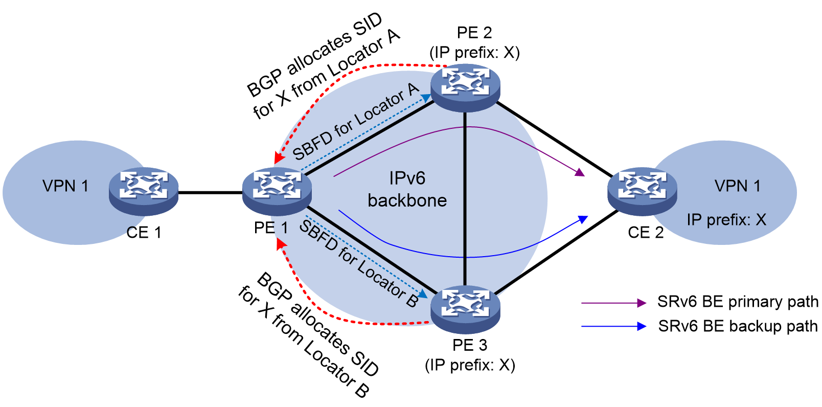
SBFD detects the connectivity of SRv6 locators as follows:
1. PE 1 sends SBFD packets as the initiator. The SRv6 locators are the destination addresses of the SBFD packets. The IP address specified in the sbfd source-ipv6 command is used as the source IP address of SBFD packets.
2. When PE 2 and PE 3 receive the SBFD packets as reflectors, they compare the remote discriminators in the packets with the locally configured discriminators.
¡ If they are consistent, the reflectors send SBFD response packets to the initiator through IPv6 routes.
¡ If they are inconsistent, the reflectors drop the received SBFD packets.
3. If the initiator can receive SBFD response packets before the detection timer expires, it determines that the SRv6 locators are reachable. If not, the initiator determines that the SRv6 locators are unreachable, and switches over to the backup path.
Restrictions and guidelines
To have this feature take effect, execute the sbfd destination ipv6 remote-discriminator command on PE 1 to configure the mappings between the detected SRv6 locators and remote discriminators. In addition, execute the sbfd local-discriminator command on PE 2 and PE 3 to configure the local discriminators on the reflector end. Make sure PE 1 have consistent discriminator settings with PE 2 and PE 3. For more information about the sbfd destination ipv6 remote-discriminator and sbfd local-discriminator commands, see BFD commands in High Availability Command Reference.
Procedure
1. Enter system view.
system-view
2. Enter SRv6 view.
segment-routing ipv6
3. Configure SBFD for SRv6 locators.
locator-sbfd enable [ template template-name ] [ prefix-list prefix-list-name ]
By default, SBFD is not configured for SRv6 locators.
Configuring a TTL processing mode for tunnels associated with a VPN instance
About this task
A tunnel associated with a VPN instance supports the following TTL processing modes:
· Pipe—When an IP or IPv6 packet enters the tunnel of the VPN instance, the ingress node adds a new header to the packet. The ingress node sets the TTL value or hop limit in the new header to 255 or the value specified by using the encapsulation source-address ip-ttl command in SRv6 view. When the packet leaves the tunnel of the VPN instance, the egress node removes the new header from the packet.The TTL value or hop limit in the original packet does not change when the packet is forwarded in the tunnel. Therefore, the public network nodes are invisible to user networks, and the tracert facility cannot show the real path in the public network.
· Uniform—When an IP or IPv6 packet enters the tunnel of the VPN instance, the ingress node adds a new header to the packet. The ingress node copies the TTL value or the hop limit of the original packet to the TTL or hop limit field of the new header. When the packet leaves the tunnel of the VPN instance, the egress node copies the remaining TTL value or hop limit in the new header back to the original packet. The TTL value or hop limit can reflect how many hops the packet has traversed in the public network. The tracert facility can show the real path along which the packet has traveled.
Restrictions and guidelines
In the current software version, you can configure a TTL processing mode only for SRv6 tunnels associated with VPN instances.
Procedure
1. Enter system view.
system-view
2. Enter VPN instance view.
ip vpn-instance vpn-instance-name
3. Configure a TTL processing mode for the tunnels associated with the VPN instance.
ttl-mode { pipe | uniform }
By default, the TTL processing mode for the tunnels associated with a VPN instance is pipe.
For more information about this command, see MPLS L3VPN configuration in MPLS Configuration Guide.
Display and maintenance commands for IP L3VPN over SRv6
Resetting BGP sessions
For BGP setting changes to take effect, you must reset or soft-reset BGP sessions. Soft-resetting BGP sessions updates BGP routing information without tearing down the BGP sessions. Resetting BGP sessions updates BGP routing information by tearing down and re-establishing the BGP sessions. Soft-reset requires that both the local router and the peer support ROUTE-REFRESH messages.
Execute the commands in this section in user view. For more information about the commands, see BGP in Layer 3—IP Routing Command Reference.
|
Task |
Command |
|
Soft-reset BGP sessions of the BGP VPNv4 address family. |
refresh bgp [ instance instance-name ] ipv6-address [ prefix-length ] { export | import } vpnv4 |
|
Reset BGP sessions of the BGP VPNv4 address family. |
reset bgp [ instance instance-name ] ipv6-address [ prefix-length ] vpnv4 |
Displaying and maintaining the running status of IP L3VPN over SRv6 VPN
Execute display commands in any view and reset commands in user view.
For more information about the commands in this section, see BGP in Layer 3—IP Routing Command Reference.
|
Task |
Command |
|
Display BGP VPNv4 peer or peer group information. |
display bgp [ instance instance-name ] peer vpnv4 { ipv6-address prefix-length | ipv6-address { log-info | verbose } } |
|
Display BGP VPNv6 peer or peer group information. |
display bgp [ instance instance-name ] peer vpnv6 [ vpn-instance vpn-instance-name ] [ ipv6-address prefix-length | { ipv6-address | group-name group-name } log-info | [ ipv6-address ] verbose ] |
|
Display BGP update group information for VPNv4 address family. |
display bgp [ instance instance-name ] update-group vpnv4 ipv6-address |
|
Display BGP update group information for VPNv6 address family. |
display bgp [ instance instance-name ] update-group vpnv6 [ vpn-instance vpn-instance-name ] [ ipv6-address ] |
|
Display information about SRv6 SIDs carried in the BGP VPNv4 routes advertised by the local device or received from the peer. |
display bgp [ instance instance-name ] routing-table ipv4 [ unicast ] vpn-instance vpn-instance-name { local-sids | received-sids } |
|
Display information about SRv6 SIDs carried in the BGP VPNv6 routes advertised by the local device or received from the peer. |
display bgp [ instance instance-name ] routing-table ipv6 [ unicast ] vpn-instance vpn-instance-name { local-sids | received-sids } |
|
Clear flap statistics for BGP VPNv4 routes. |
reset bgp [ instance instance-name ] flap-info vpnv4 [ ipv4-address [ mask | mask-length ] | as-path-acl as-path-acl-number | peer ipv6-address [ prefix-length ] ] |
IP L3VPN over SRv6 configuration examples
Example: Configuring IP L3VPN over SRv6 BE
Network configuration
As shown in Figure 14, the backbone network is an IPv6 network, and VPN 1 is an IPv4 network. Deploy IP L3VPN over SRv6 between PE 1 and PE 2 and use an SRv6 tunnel to transmit VPNv4 traffic between the PEs.
· Configure EBGP to exchange VPN routing information between the CEs and PEs.
· Configure IPv6 IS-IS on the PEs in the same AS to realize IPv6 network connectivity.
· Configure MP-IBGP to exchange VPNv4 routing information between the PEs.
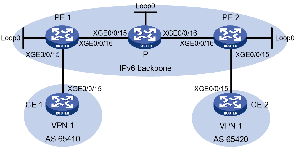
Table 1 Interface and IP address assignment
|
Device |
Interface |
IP address |
Device |
Interface |
IP address |
|
CE 1 |
XGE0/0/15 |
10.1.1.2/24 |
PE 2 |
Loop0 |
3::3/128 |
|
PE 1 |
Loop0 |
1::1/128 |
|
XGE0/0/15 |
10.2.1.1/24 |
|
|
XGE0/0/15 |
10.1.1.1/24 |
|
XGE0/0/16 |
2002::1/96 |
|
|
XGE0/0/16 |
2001::1/96 |
CE 2 |
XGE0/0/15 |
10.2.1.2/24 |
|
P |
Loop0 |
2::2/128 |
|
|
|
|
|
XGE0/0/15 |
2001::2/96 |
|
|
|
|
|
XGE0/0/16 |
2002::2/96 |
|
|
|
Procedure
1. Configure IPv6 IS-IS on the PEs and device P for network connectivity between the devices:
# Configure PE 1.
<PE1> system-view
[PE1] isis 1
[PE1-isis-1] is-level level-1
[PE1-isis-1] cost-style wide
[PE1-isis-1] network-entity 10.1111.1111.1111.00
[PE1-isis-1] address-family ipv6 unicast
[PE1-isis-1-ipv6] quit
[PE1-isis-1] quit
[PE1] interface loopback 0
[PE1-LoopBack0] ipv6 address 1::1 128
[PE1-LoopBack0] isis ipv6 enable 1
[PE1-LoopBack0] quit
[PE1] interface ten-gigabitethernet 0/0/16
[PE1-Ten-GigabitEthernet0/0/16] ipv6 address 2001::1 96
[PE1-Ten-GigabitEthernet0/0/16] isis ipv6 enable
[PE1-Ten-GigabitEthernet0/0/16] quit
# Configure P.
<P> system-view
[P] isis
[P-isis-1] is-level level-1
[P-isis-1] cost-style wide
[P-isis-1] network-entity 10.2222.2222.2222.00
[P-isis-1] address-family ipv6 unicast
[P-isis-1-ipv6] quit
[P-isis-1] quit
[P] interface loopback 0
[P-LoopBack0] ipv6 address 2::2 128
[P-LoopBack0] isis ipv6 enable
[P-LoopBack0] quit
[P] interface ten-gigabitethernet 0/0/15
[P-Ten-GigabitEthernet0/0/15] ipv6 address 2001::2 96
[P-Ten-GigabitEthernet0/0/15] isis ipv6 enable
[P-Ten-GigabitEthernet0/0/15] quit
[P] interface ten-gigabitethernet 0/0/16
[P-Ten-GigabitEthernet0/0/16] ipv6 address 2002::2 96
[P-Ten-GigabitEthernet0/0/16] isis ipv6 enable
[P-Ten-GigabitEthernet0/0/16] quit
# Configure PE 2.
<PE2> system-view
[PE2] isis
[PE2-isis-1] is-level level-1
[PE2-isis-1] cost-style wide
[PE2-isis-1] network-entity 10.3333.3333.3333.00
[PE2-isis-1] address-family ipv6 unicast
[PE2-isis-1-ipv6] quit
[PE2-isis-1] quit
[PE2] interface loopback 0
[PE2-LoopBack0] ipv6 address 3::3 128
[PE2-LoopBack0] isis ipv6 enable
[PE2-LoopBack0] quit
[PE2] interface ten-gigabitethernet 0/0/16
[PE2-Ten-GigabitEthernet0/0/16] ipv6 address 2002::1 96
[PE2-Ten-GigabitEthernet0/0/16] isis ipv6 enable
[PE2-Ten-GigabitEthernet0/0/16] quit
# Verify that PE 1, P, and PE 2 have established IPv6 IS-IS neighbor relationships and the neighbor state is up with the display isis peer command.
# Verify that PE 1 and PE 2 each learn a route destined for the loopback interface of each other with the display isis route ipv6 command.
2. Configure VPN instance settings on PE 1 and PE 2 and verify that each CE can access its local PE:
# Configure PE 1.
[PE1] ip vpn-instance vpn1
[PE1-vpn-instance-vpn1] route-distinguisher 100:1
[PE1-vpn-instance-vpn1] vpn-target 111:1
[PE1-vpn-instance-vpn1] quit
[PE1] interface ten-gigabitethernet 0/0/15
[PE1-Ten-GigabitEthernet0/0/15] ip binding vpn-instance vpn1
[PE1-Ten-GigabitEthernet0/0/15] ip address 10.1.1.1 24
[PE1-Ten-GigabitEthernet0/0/15] quit
# Configure PE 2.
[PE2] ip vpn-instance vpn1
[PE2-vpn-instance-vpn1] route-distinguisher 100:1
[PE2-vpn-instance-vpn1] vpn-target 111:1
[PE2-vpn-instance-vpn1] quit
[PE2] interface ten-gigabitethernet 0/0/15
[PE2-Ten-GigabitEthernet0/0/15] ip binding vpn-instance vpn1
[PE2-Ten-GigabitEthernet0/0/15] ip address 10.2.1.1 24
[PE2-Ten-GigabitEthernet0/0/15] quit
# Configure IP addresses for the interfaces on the CEs, as shown in Figure 14. (Details not shown.)
# Display VPN instance settings on each PE. This step uses PE 1 as an example.
[PE1] display ip vpn-instance
Total VPN-Instances configured : 1
Total IPv4 VPN-Instances configured : 1
Total IPv6 VPN-Instances configured : 1
VPN-Instance Name RD Address family Create time
vpn1 100:1 N/A 2019/08/12 13:59:39
# Verify that each PE can ping its local CE. This step uses PE 1 and CE 1 as an example.
[PE1] ping -vpn-instance vpn1 10.1.1.2
Ping 10.1.1.2 (10.1.1.2): 56 data bytes, press CTRL+C to break
56 bytes from 10.1.1.2: icmp_seq=0 ttl=255 time=2.000 ms
56 bytes from 10.1.1.2: icmp_seq=1 ttl=255 time=0.000 ms
56 bytes from 10.1.1.2: icmp_seq=2 ttl=255 time=1.000 ms
56 bytes from 10.1.1.2: icmp_seq=3 ttl=255 time=0.000 ms
56 bytes from 10.1.1.2: icmp_seq=4 ttl=255 time=0.000 ms
--- Ping statistics for 10.1.1.2 in VPN instance vpn1 ---
5 packet(s) transmitted, 5 packet(s) received, 0.0% packet loss
round-trip min/avg/max/std-dev = 0.000/0.600/2.000/0.800 ms
3. Set up an EBGP peer relationship between each PE and its local CE and distribute VPN routes to EBGP:
# Configure CE 1.
<CE1> system-view
[CE1] bgp 65410
[CE1-bgp-default] peer 10.1.1.1 as-number 100
[CE1-bgp-default] address-family ipv4 unicast
[CE1-bgp-default-ipv4] peer 10.1.1.1 enable
[CE1-bgp-default-ipv4] import-route direct
[CE1-bgp-default-ipv4] quit
[CE1-bgp-default] quit
# Configure CE 2 in the same way as CE 1 is configured. (Details not shown.)
# Configure PE 1.
[PE1] bgp 100
[PE1-bgp-default] router-id 1.1.1.1
[PE1-bgp-default] ip vpn-instance vpn1
[PE1-bgp-default-vpn1] peer 10.1.1.2 as-number 65410
[PE1-bgp-default-vpn1] address-family ipv4 unicast
[PE1-bgp-default-ipv4-vpn1] peer 10.1.1.2 enable
[PE1-bgp-default-ipv4-vpn1] quit
[PE1-bgp-default-vpn1] quit
# Configure PE 2 in the same way PE 1 is configured. (Details not shown.)
# Verify that the PEs have established BGP peer relationships with their local CEs and the peers are in established state with the display bgp peer ipv4 vpn-instance command.
4. Set up an MP-IBGP peer relationship between PE 1 and PE 2:
# Configure PE 1.
[PE1] bgp 100
[PE1-bgp-default] peer 3::3 as-number 100
[PE1-bgp-default] peer 3::3 connect-interface loopback 0
[PE1-bgp-default] address-family vpnv4
[PE1-bgp-default-vpnv4] peer 3::3 enable
[PE1-bgp-default-vpnv4] quit
[PE1-bgp-default] quit
# Configure PE 2.
[PE2] bgp 100
[PE2-bgp-default] peer 1::1 as-number 100
[PE2-bgp-default] peer 1::1 connect-interface loopback 0
[PE2-bgp-default] address-family vpnv4
[PE2-bgp-default-vpnv4] peer 1::1 enable
[PE2-bgp-default-vpnv4] quit
[PE2-bgp-default] quit
# Verify that the PEs have established a BGP peer relationship and the peers are in established state with the display bgp peer vpnv4 command.
5. Specify a source address for the outer IPv6 header of SRv6-encapsulated IP L3VPN packets on PE 1 and PE 2:
# Configure PE 1.
[PE1] segment-routing ipv6
[PE1-segment-routing-ipv6] encapsulation source-address 1::1
# Configure PE 2.
[PE2] segment-routing ipv6
[PE2-segment-routing-ipv6] encapsulation source-address 3::3
6. Configure SRv6 locators on PEs to be advertised through IGP:
# Configure PE 1.
[PE1-segment-routing-ipv6] locator aaa ipv6-prefix 1:2::1:0 96 static 8
[PE1-segment-routing-ipv6-locator-aaa] quit
[PE1-segment-routing-ipv6] quit
[PE1] isis 1
[PE1-isis-1] address-family ipv6 unicast
[PE1-isis-1-ipv6] segment-routing ipv6 locator aaa
[PE1-isis-1-ipv6] quit
[PE1-isis-1] quit
# Configure PE 2.
[PE2-segment-routing-ipv6] locator bbb ipv6-prefix 6:5::1:0 96 static 8
[PE2-segment-routing-ipv6-locator-bbb] quit
[PE2-segment-routing-ipv6] quit
[PE2] isis 1
[PE2-isis-1] address-family ipv6 unicast
[PE2-isis-1-ipv6] segment-routing ipv6 locator bbb
[PE2-isis-1-ipv6] quit
[PE2-isis-1] quit
7. Add End.DT4 SIDs to private network routes on PE 1 and PE 2:
# Configure PE 1.
[PE1] bgp 100
[PE1-bgp-default] ip vpn-instance vpn1
[PE1-bgp-default-vpn1] address-family ipv4 unicast
[PE1-bgp-default-ipv4-vpn1] segment-routing ipv6 locator aaa
[PE1-bgp-default-ipv4-vpn1] quit
[PE1-bgp-default-vpn1] quit
[PE1-bgp-default] quit
# Configure PE 2.
[PE2] bgp 100
[PE2-bgp-default] ip vpn-instance vpn1
[PE2-bgp-default-vpn1] address-family ipv4 unicast
[PE2-bgp-default-ipv4-vpn1] segment-routing ipv6 locator bbb
[PE2-bgp-default-ipv4-vpn1] quit
[PE2-bgp-default-vpn1] quit
[PE2-bgp-default] quit
# Verify that the PEs have distributed the End.DT4 SIDs to the routing table and generated SRv6 routes. This step uses PE 1 as an example.
[PE1] display ipv6 routing-table protocol srv6
Summary count : 1
SRv6 Routing table status : <Active>
Summary count : 1
Destination: 1:2::101/128 Protocol : SRv6
NextHop : ::1 Preference: 4
Interface : InLoop0 Cost : 0
SRv6 Routing table status : <Inactive>
Summary count : 0
8. Enable IPv6 peers on the PEs to exchange End.DT4 SIDs and enable the SID-route-recursion feature:
# Configure PE 1.
[PE1] bgp 100
[PE1-bgp-default] address-family vpnv4
[PE1-bgp-default-vpnv4] peer 3::3 prefix-sid
[PE1-bgp-default-vpnv4] quit
[PE1-bgp-default] ip vpn-instance vpn1
[PE1-bgp-default-vpn1] address-family ipv4 unicast
[PE1-bgp-default-ipv4-vpn1] segment-routing ipv6 best-effort
[PE1-bgp-default-ipv4-vpn1] quit
[PE1-bgp-default-vpn1] quit
[PE1-bgp-default] quit
# Configure PE 2.
[PE2] bgp 100
[PE2-bgp-default] address-family vpnv4
[PE2-bgp-default-vpnv4] peer 1::1 prefix-sid
[PE2-bgp-default-vpnv4] quit
[PE2-bgp-default] ip vpn-instance vpn1
[PE2-bgp-default-vpn1] address-family ipv4 unicast
[PE2-bgp-default-ipv4-vpn1] segment-routing ipv6 best-effort
[PE2-bgp-default-ipv4-vpn1] quit
[PE2-bgp-default-vpn1] quit
[PE2-bgp-default] quit
# Display BGP VPNv4 routing information on each PE and verify that the routes advertised by the PEs have the SID attribute. This step uses PE 1 as an example.
[PE1] display bgp routing-table vpnv4 10.2.1.0
BGP local router ID: 1.1.1.1
Local AS number: 100
Route distinguisher: 100:1(vpn1)
Total number of routes: 1
Paths: 1 available, 1 best
BGP routing table information of 10.2.1.0/24:
From : 3::3 (3.3.3.3)
Rely nexthop : FE80::2A96:34FF:FE9D:216
Original nexthop: 3::3
Out interface : Ten-GigabitEthernet0/0/16
Route age : 00h14m23s
OutLabel : 3
Ext-Community : <RT: 111:1>
RxPathID : 0x0
TxPathID : 0x0
PrefixSID : End.DT4 SID <6:5::101>
…
Verifying the configuration
# Display IPv4 routing table information on the PEs and verify that each PE has a route destined for the remote CE and the next hop of the route is locator of the End.DT4 SID. This step uses PE 1 as an example.
[PE1] display ip routing-table vpn-instance vpn1
Destinations : 11 Routes : 11
Destination/Mask Proto Pre Cost NextHop Interface
0.0.0.0/32 Direct 0 0 127.0.0.1 InLoop0
10.1.1.0/24 Direct 0 0 10.1.1.1 XGE0/0/15
10.1.1.0/32 Direct 0 0 10.1.1.1 XGE0/0/15
10.1.1.1/32 Direct 0 0 127.0.0.1 InLoop0
10.1.1.255/32 Direct 0 0 10.1.1.1 XGE0/0/15
10.2.1.0/24 BGP 255 0 6:5:: XGE0/0/16
127.0.0.0/8 Direct 0 0 127.0.0.1 InLoop0
127.0.0.0/32 Direct 0 0 127.0.0.1 InLoop0
127.0.0.1/32 Direct 0 0 127.0.0.1 InLoop0
127.255.255.255/32 Direct 0 0 127.0.0.1 InLoop0
255.255.255.255/32 Direct 0 0 127.0.0.1 InLoop0
# Verify that CE 1 and CE 2 can ping each other. (Details not shown.)
Example: Configuring IPv4 L3VPN over G-SRv6 (with COC32 locators of 32-bit G-SRv6 compression)
Network configuration
As shown in Figure 16, the backbone network is an IPv6 network, and VPN aaa is an IPv4 network. Deploy an SRv6 TE policy tunnel between PE 1 and PE 2 in the IPv6 network and use the SRv6 TE policy tunnel to transmit end-to-end VPN traffic.
· Because a large number of devices exist in the backbone network, the SID list for the optimal candidate path of the SRv6 TE policy contains many SRv6 SIDs. To reduce the SRH length for packets, use the G-SRv6 compression solution.
· The SRv6 nodes in the backbone network use COC32 locators, and assign SIDs with the COC flag from the COC32 locators.
· As shown in Figure 15, to prevent packet forwarding issues, appropriately plan the common prefix for the locators in the AS. Specify the common prefix as A:1:1:A:: with 64-bit length for COC32 locators on all devices. In addition, specify the IPv6 address prefix length for the locators as 80 bits, the static portion length for COC32 locators as 8 bits, and the Args portion length as 16 bits. Through calculation, the dynamic portion length in COC32 locators is 8 bits, and the MBZ length is 16 bits.
Figure 15 COC32 locator plan in the AS
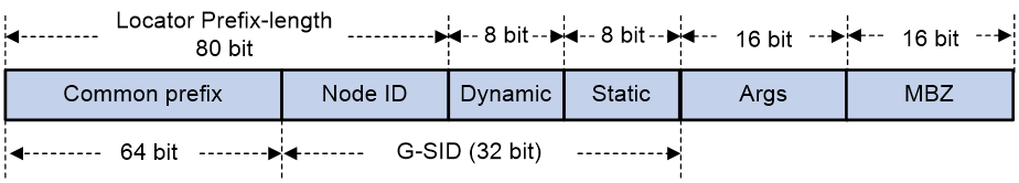
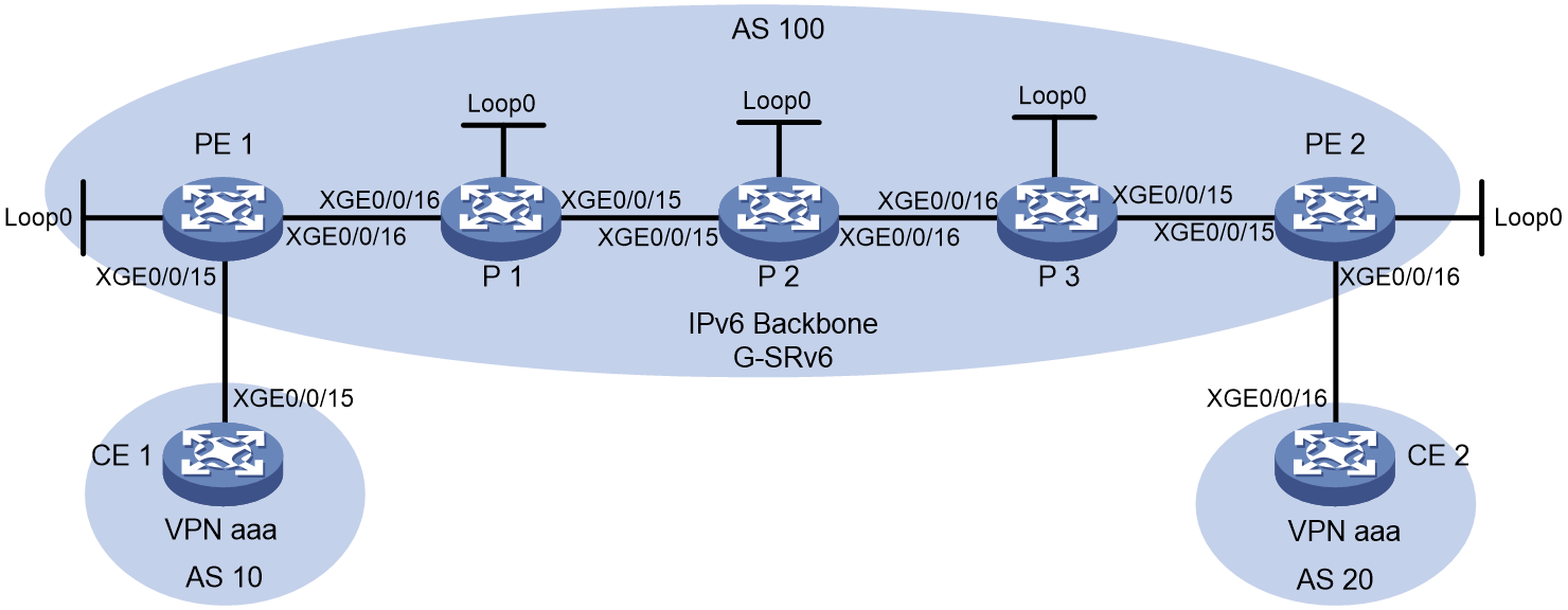
|
Device |
Interfaces |
IP address |
Device |
Interfaces |
IP address |
|
CE 1 |
XGE0/0/15 |
10.1.1.1/30 |
CE 2 |
XGE0/0/16 |
20.1.1.1/30 |
|
|
Loop0 |
11.11.11.11/32 |
|
Loop0 |
22.22.22.22/32 |
|
PE 1 |
Loop0 |
1::1/128 |
PE 2 |
Loop0 |
5::5/128 |
|
|
XGE0/0/15 |
10.1.1.2/30 |
|
XGE0/0/16 |
20.1.1.2/30 |
|
|
XGE0/0/16 |
12:1:1::1/126 |
|
XGE0/0/15 |
45:1:1::2/126 |
|
P 1 |
Loop0 |
2::2/128 |
P 2 |
Loop0 |
3::3/128 |
|
|
XGE0/0/15 |
23:1:1::1/126 |
|
XGE0/0/15 |
23:1:1::2/126 |
|
|
XGE0/0/16 |
12:1:1::2/126 |
|
XGE0/0/16 |
34:1:1::1/126 |
|
P 3 |
Loop0 |
4::4/128 |
|
|
|
|
|
XGE0/0/15 |
45:1:1::1/126 |
|
|
|
|
|
XGE0/0/16 |
34:1:1::2/126 |
|
|
|
Procedure
1. Configure CE 1:
# Configure IP addresses for the interfaces.
<CE1> system-view
[CE1] sysname CE1
[CE1] interface ten-gigabitethernet 0/0/15
[CE1-Ten-GigabitEthernet0/0/15] ip address 10.1.1.1 30
[CE1-Ten-GigabitEthernet0/0/15] quit
[CE1] interface loopback 0
[CE1-LoopBack0] ip address 11.11.11.11 32
[CE1-LoopBack0] quit
# Create EBGP peers between the PE and CE, and import direct routes.
[CE1] bgp 10
[CE1-bgp-default] router-id 11.11.11.11
[CE1-bgp-default] peer 10.1.1.2 as-number 100
[CE1-bgp-default] address-family ipv4 unicast
[CE1-bgp-default-ipv4] peer 10.1.1.2 enable
[CE1-bgp-default-ipv4] import-route direct
[CE1-bgp-default-ipv4] quit
[CE1-bgp-default] quit
2. Configure CE 2:
# Configure IP addresses for the interfaces.
<CE2> system-view
[CE2] sysname CE2
[CE2] interface ten-gigabitethernet 0/0/16
[CE2-Ten-GigabitEthernet0/0/16] ip address 20.1.1.1 30
[CE2-Ten-GigabitEthernet0/0/16] quit
[CE2] interface loopback 0
[CE2-LoopBack0] ip address 22.22.22.22 32
[CE2-LoopBack0] quit
# Create EBGP peers between the PE and CE, and import direct routes.
[CE2] bgp 20
[CE2-bgp-default] router-id 22.22.22.22
[CE2-bgp-default] peer 20.1.1.2 as-number 100
[CE2-bgp-default] address-family ipv4 unicast
[CE2-bgp-default-ipv4] peer 20.1.1.2 enable
[CE2-bgp-default-ipv4] import-route direct
[CE2-bgp-default-ipv4] quit
[CE2-bgp-default] quit
3. Configure PE 1:
# Configure the VPN instance on PE 1 to connect the CE to PE.
<PE1> system-view
[PE1] sysname PE1
[PE1] ip vpn-instance aaa
[PE1-vpn-instance-aaa] route-distinguisher 100:1
[PE1-vpn-instance-aaa] vpn-target 200:1 both
[PE1-vpn-instance-aaa] quit
# Configure IP addresses for the interfaces.
[PE1] interface loopback 0
[PE1-LoopBack0] ipv6 address 1::1 128
[PE1-LoopBack0] quit
[PE1] interface ten-gigabitethernet 0/0/15
[PE1-Ten-GigabitEthernet0/0/15] ip binding vpn-instance aaa
[PE1-Ten-GigabitEthernet0/0/15] ip address 10.1.1.2 30
[PE1-Ten-GigabitEthernet0/0/15] quit
[PE1] interface ten-gigabitethernet 0/0/16
[PE1-Ten-GigabitEthernet0/0/16] ipv6 address 12:1:1::1 126
[PE1-Ten-GigabitEthernet0/0/16] quit
# Configure IPv6 IS-IS to implement backbone network intercommunication.
[PE1] isis 1
[PE1-isis-1] is-level level-2
[PE1-isis-1] cost-style wide
[PE1-isis-1] network-entity 00.0000.0000.0001.00
[PE1-isis-1] address-family ipv6 unicast
[PE1-isis-1-ipv6] quit
[PE1-isis-1] quit
[PE1] interface ten-gigabitethernet 0/0/16
[PE1-Ten-GigabitEthernet0/0/16] isis ipv6 enable 1
[PE1-Ten-GigabitEthernet0/0/16] quit
[PE1] interface loopback 0
[PE1-LoopBack0] isis ipv6 enable 1
[PE1-LoopBack0] quit
# Configure an SRv6 locator on the PE to be advertised by IGP, and enable SRv6 compression.
[PE1] segment-routing ipv6
[PE1-segment-routing-ipv6] srv6 compress enable
[PE1-segment-routing-ipv6] locator a ipv6-prefix A:1:1:A:1:: 80 common-prefix 64 coc32 static 8 args 16
[PE1-segment-routing-ipv6-locator-a] quit
[PE1-segment-routing-ipv6] quit
[PE1] isis 1
[PE1-isis-1] address-family ipv6 unicast
[PE1-isis-1-ipv6] segment-routing ipv6 locator a auto-sid-coc32
[PE1-isis-1-ipv6] srv6 compress enable
[PE1-isis-1-ipv6] quit
[PE1-isis-1] quit
# Specify a source address for the outer IPv6 header of SRv6-encapsulated IP L3VPN packets on the PE.
[PE1] segment-routing ipv6
[PE1-segment-routing-ipv6] encapsulation source-address 1::1
# Configure the source address of SBFD packets on PE 1.
[PE1] sbfd source-ipv6 1::1
# Configure a static SID list on the PE that contains SRv6 SIDs with the COC flag, specify the static SID list for an SRv6 TE policy, and enable SBFD for the SRv6 TE policy, ensuring that the SRv6 TE policy tunnel can forward services correctly.
In the static SID list:
¡ The first hop is the End.X(COC32) SID of the link from P 1 to P 2. The SRv6 SID in the encapsulated SRH is still 128 bits long without being compressed. The next SID will be compressed.
¡ The second hop is the End(COC32) SID of P 2. The SRv6 SID in the encapsulated SRH is compressed to 32 bits long.
¡ The third hop is the End.X(COC32) SID of the link from P 3 to PE 2. The SRv6 SID in the encapsulated SRH is compressed to 32 bits long.
¡ The fourth hop is the End SID of PE 2. The SRv6 SID in the encapsulated SRH is compressed to 32 bits long. The next SID will not be compressed.
[PE1] segment-routing ipv6
[PE1-segment-routing-ipv6] traffic-engineering
[PE1-srv6-te] srv6-policy locator a
[PE1-srv6-te] segment-list a
[PE1-srv6-te-sl-a] index 10 coc32 ipv6 A:1:1:A:2:20:: 64
[PE1-srv6-te-sl-a] index 20 coc32 ipv6 A:1:1:A:3:10:: 64
[PE1-srv6-te-sl-a] index 30 coc32 ipv6 A:1:1:A:4:20:: 64
[PE1-srv6-te-sl-a] index 40 ipv6 A:1:1:A:5:10::
[PE1-srv6-te-sl-a] quit
[PE1-srv6-te] policy a
[PE1-srv6-te-policy-a] color 10 end-point ipv6 5::5
[PE1-srv6-te-policy-a] sbfd enable remote 1000001
[PE1-srv6-te-policy-a] candidate-paths
[PE1-srv6-te-policy-a-path] preference 200
[PE1-srv6-te-policy-a-path-pref-200] explicit segment-list a
[PE1-srv6-te-policy-a-path-pref-200] quit
[PE1-srv6-te-policy-a-path] quit
[PE1-srv6-te-policy-a] quit
[PE1-srv6-te] quit
[PE1-segment-routing-ipv6] quit
# Create EBGP peers between the PE and CE, and import VPN routes.
[PE1] bgp 100
[PE1-bgp-default] router-id 1.1.1.1
[PE1-bgp-default] ip vpn-instance aaa
[PE1-bgp-default-aaa] peer 10.1.1.1 as-number 10
[PE1-bgp-default-aaa] address-family ipv4 unicast
[PE1-bgp-default-ipv4-aaa] peer 10.1.1.1 enable
[PE1-bgp-default-ipv4-aaa] quit
[PE1-bgp-default-aaa] quit
# Create MP-IBGP peers between PE 1 and PE 2.
[PE1-bgp-default] peer 5::5 as-number 100
[PE1-bgp-default] peer 5::5 connect-interface loopback 0
[PE1-bgp-default] address-family vpnv4
[PE1-bgp-default-vpnv4] peer 5::5 enable
[PE1-bgp-default-vpnv4] quit
[PE1-bgp-default] quit
# Enable exchange of End.DT4 SIDs between IPv6 peers on PE 1, and enable recursion of VPN routes to the SRv6 TE policy tunnel.
[PE1] bgp 100
[PE1-bgp-default] address-family vpnv4
[PE1-bgp-default-vpnv4] peer 5::5 prefix-sid
[PE1-bgp-default-vpnv4] quit
[PE1-bgp-default] ip vpn-instance aaa
[PE1-bgp-default-aaa] address-family ipv4 unicast
[PE1-bgp-default-ipv4-aaa] segment-routing ipv6 locator a
[PE1-bgp-default-ipv4-aaa] segment-routing ipv6 traffic-engineering
[PE1-bgp-default-ipv4-aaa] quit
[PE1-bgp-default-aaa] quit
[PE1-bgp-default] quit
# Configure a routing policy and a tunnel policy on PE 1 to steer VPN service traffic to the specified SRv6 TE policy through the routing policy and ensure that the SRv6 TE policy is the optimal tunnel.
[PE1] route-policy a permit node 10
[PE1-route-policy-a-10] apply extcommunity color 00:10
[PE1-route-policy-a-10] quit
[PE1] bgp 100
[PE1-bgp-default] address-family vpnv4
[PE1-bgp-default-vpnv4] peer 5::5 route-policy a import
[PE1-bgp-default-vpnv4] quit
[PE1-bgp-default] quit
[PE1] tunnel-policy a
[PE1-tunnel-policy-a] select-seq srv6-policy load-balance-number 1
[PE1-tunnel-policy-a] quit
[PE1] ip vpn-instance vpn1
[PE1-vpn-instance-vpn1] tnl-policy a
[PE1-vpn-instance-vpn1] quit
4. Configure P 1:
# Configure IP addresses for the interfaces.
[P1] interface loopback 0
[P1-LoopBack0] ipv6 address 2::2 128
[P1-LoopBack0] quit
[P1] interface ten-gigabitethernet 0/0/15
[P1-Ten-GigabitEthernet0/0/15] ipv6 address 23:1:1::1 126
[P1-Ten-GigabitEthernet0/0/15] quit
[P1] interface ten-gigabitethernet 0/0/16
[P1-Ten-GigabitEthernet0/0/16] ipv6 address 12:1:1::2 126
[P1-Ten-GigabitEthernet0/0/16] quit
# Configure IPv6 IS-IS to implement backbone network intercommunication.
[P1] isis 1
[P1-isis-1] is-level level-2
[P1-isis-1] cost-style wide
[P1-isis-1] network-entity 00.0000.0000.0002.00
[P1-isis-1] address-family ipv6 unicast
[P1-isis-1-ipv6] quit
[P1-isis-1] quit
[P1] interface ten-gigabitethernet 0/0/15
[P1-Ten-GigabitEthernet0/0/15] isis ipv6 enable 1
[P1-Ten-GigabitEthernet0/0/15] quit
[P1] interface ten-gigabitethernet 0/0/16
[P1-Ten-GigabitEthernet0/0/16] isis ipv6 enable 1
[P1-Ten-GigabitEthernet0/0/16] quit
[P1] interface loopback 0
[P1-LoopBack0] isis ipv6 enable 1
[P1-LoopBack0] quit
# Configure an SRv6 locator on P 1 to be advertised by IGP, and enable SRv6 compression.
[P1] segment-routing ipv6
[P1-segment-routing-ipv6] srv6 compress enable
[P1-segment-routing-ipv6] locator b ipv6-prefix A:1:1:A:2:: 80 common-prefix 64 coc32 static 8 args 16
[P1-segment-routing-ipv6-locator-b] opcode 32 end-x-coc32 interface Ten-GigabitEthernet0/0/15 nexthop 23:1:1::2 no-flavor
[P1-segment-routing-ipv6-locator-b] quit
[P1-segment-routing-ipv6] quit
[P1] isis 1
[P1-isis-1] address-family ipv6 unicast
[P1-isis-1-ipv6] segment-routing ipv6 locator b auto-sid-coc32
[P1-isis-1-ipv6] srv6 compress enable
[P1-isis-1-ipv6] quit
[P1-isis-1] quit
5. Configure P 2:
# Configure IP addresses for the interfaces.
[P2] interface loopback 0
[P2-LoopBack0] ipv6 address 3::3 128
[P2-LoopBack0] quit
[P2] interface ten-gigabitethernet 0/0/15
[P2-Ten-GigabitEthernet0/0/15] ipv6 address 23:1:1::2 126
[P2-Ten-GigabitEthernet0/0/15] quit
[P2] interface ten-gigabitethernet 0/0/16
[P2-Ten-GigabitEthernet0/0/16] ipv6 address 34:1:1::1 126
[P2-Ten-GigabitEthernet0/0/16] quit
# Configure IPv6 IS-IS to implement backbone network intercommunication.
[P2] isis 1
[P2-isis-1] is-level level-2
[P2-isis-1] cost-style wide
[P2-isis-1] network-entity 00.0000.0000.0003.00
[P2-isis-1] address-family ipv6 unicast
[P2-isis-1-ipv6] quit
[P2-isis-1] quit
[P2] interface ten-gigabitethernet 0/0/15
[P2-Ten-GigabitEthernet0/0/15] isis ipv6 enable 1
[P2-Ten-GigabitEthernet0/0/15] quit
[P2] interface ten-gigabitethernet 0/0/16
[P2-Ten-GigabitEthernet0/0/16] isis ipv6 enable 1
[P2-Ten-GigabitEthernet0/0/16] quit
[P2] interface loopback 0
[P2-LoopBack0] isis ipv6 enable 1
[P2-LoopBack0] quit
# Configure an SRv6 locator on P 2 to be advertised by IGP, and enable SRv6 compression.
[P2] segment-routing ipv6
[P2-segment-routing-ipv6] srv6 compress enable
[P2-segment-routing-ipv6] locator c ipv6-prefix A:1:1:A:3:: 80 common-prefix 64 coc32 static 8 args 16
[P2-segment-routing-ipv6-locator-c] opcode 16 end-coc32 no-flavor
[P2-segment-routing-ipv6-locator-c] quit
[P2-segment-routing-ipv6] quit
[P2] isis 1
[P2-isis-1] address-family ipv6 unicast
[P2-isis-1-ipv6] segment-routing ipv6 locator c auto-sid-coc32
[P2-isis-1-ipv6] srv6 compress enable
[P2-isis-1-ipv6] quit
[P2-isis-1] quit
6. Configure P 3:
# Configure IP addresses for the interfaces.
[P3] interface loopback 0
[P3-LoopBack0] ipv6 address 4::4 128
[P3-LoopBack0] quit
[P3] interface ten-gigabitethernet 0/0/15
[P3-Ten-GigabitEthernet0/0/15] ipv6 address 45:1:1::1 126
[P3-Ten-GigabitEthernet0/0/15] quit
[P3] interface ten-gigabitethernet 0/0/16
[P3-Ten-GigabitEthernet0/0/16] ipv6 address 34:1:1::2 126
[P3-Ten-GigabitEthernet0/0/16] quit
# Configure IPv6 IS-IS to implement backbone network intercommunication.
[P3] isis 1
[P3-isis-1] is-level level-2
[P3-isis-1] cost-style wide
[P3-isis-1] network-entity 00.0000.0000.0004.00
[P3-isis-1] address-family ipv6 unicast
[P3-isis-1-ipv6] quit
[P3-isis-1] quit
[P3] interface ten-gigabitethernet 0/0/15
[P3-Ten-GigabitEthernet0/0/15] isis ipv6 enable 1
[P3-Ten-GigabitEthernet0/0/15] quit
[P3] interface ten-gigabitethernet 0/0/16
[P3-Ten-GigabitEthernet0/0/16] isis ipv6 enable 1
[P3-Ten-GigabitEthernet0/0/16] quit
[P3] interface loopback 0
[P3-LoopBack0] isis ipv6 enable 1
[P3-LoopBack0] quit
# Configure an SRv6 locator on P 3 to be advertised by IGP, and enable SRv6 compression.
[P3] segment-routing ipv6
[P3-segment-routing-ipv6] srv6 compress enable
[P3-segment-routing-ipv6] locator d ipv6-prefix A:1:1:A:4:: 80 common-prefix 64 coc32 static 8 args 16
[P3-segment-routing-ipv6-locator-d] opcode 32 end-x-coc32 interface Ten-GigabitEthernet0/0/15 nexthop 45:1:1::2 no-flavor
[P3-segment-routing-ipv6-locator-d] quit
[P3-segment-routing-ipv6] quit
[P3] isis 1
[P3-isis-1] address-family ipv6 unicast
[P3-isis-1-ipv6] segment-routing ipv6 locator d auto-sid-coc32
[P3-isis-1-ipv6] srv6 compress enable
[P3-isis-1-ipv6] quit
[P3-isis-1] quit
7. Configure PE 2:
# Configure the VPN instance on PE 2 to connect the CE to PE.
<PE2> system-view
[PE2] sysname PE2
[PE2] ip vpn-instance aaa
[PE2-vpn-instance-aaa] route-distinguisher 100:1
[PE2-vpn-instance-aaa] vpn-target 200:1 both
[PE2-vpn-instance-aaa] quit
# Configure IP addresses for the interfaces.
[PE2] interface loopback 0
[PE2-LoopBack0] ipv6 address 5::5 128
[PE2-LoopBack0] quit
[PE2] interface ten-gigabitethernet 0/0/16
[PE2-Ten-GigabitEthernet0/0/16] ip binding vpn-instance aaa
[PE2-Ten-GigabitEthernet0/0/16] ip address 20.1.1.2 30
[PE2-Ten-GigabitEthernet0/0/16] quit
[PE2] interface ten-gigabitethernet 0/0/15
[PE2-Ten-GigabitEthernet0/0/15] ipv6 address 45:1:1::2 126
[PE2-Ten-GigabitEthernet0/0/15] quit
# Configure IPv6 IS-IS to implement backbone network intercommunication.
[PE2] isis 1
[PE2-isis-1] is-level level-2
[PE2-isis-1] cost-style wide
[PE2-isis-1] network-entity 00.0000.0000.0005.00
[PE2-isis-1] address-family ipv6 unicast
[PE2-isis-1-ipv6] quit
[PE2-isis-1] quit
[PE2] interface ten-gigabitethernet 0/0/15
[PE2-Ten-GigabitEthernet0/0/15] isis ipv6 enable 1
[PE2-Ten-GigabitEthernet0/0/15] quit
[PE2] interface loopback 0
[PE2-LoopBack0] isis ipv6 enable 1
[PE2-LoopBack0] quit
# Configure an SRv6 locator on the PE to be advertised by IGP, and enable SRv6 compression.
[PE2] segment-routing ipv6
[PE2-segment-routing-ipv6] srv6 compress enable
[PE2-segment-routing-ipv6] locator e ipv6-prefix A:1:1:A:5:: 80 common-prefix 64 coc32 static 8 args 16
[PE2-segment-routing-ipv6-locator-e] opcode 16 end no-flavor
[PE2-segment-routing-ipv6-locator-e] quit
[PE2-segment-routing-ipv6] quit
[PE2] isis 1
[PE2-isis-1] address-family ipv6 unicast
[PE2-isis-1-ipv6] segment-routing ipv6 locator e auto-sid-coc32
[PE2-isis-1-ipv6] srv6 compress enable
[PE2-isis-1-ipv6] quit
[PE2-isis-1] quit
# Specify a source address for the outer IPv6 header of SRv6-encapsulated IP L3VPN packets on the PE.
[PE2] segment-routing ipv6
[PE2-segment-routing-ipv6] encapsulation source-address 5::5
# Create EBGP peers between the PE and CE, and import VPN routes.
[PE2] bgp 100
[PE2-bgp-default] router-id 5.5.5.5
[PE2-bgp-default] ip vpn-instance aaa
[PE2-bgp-default-aaa] peer 20.1.1.1 as-number 20
[PE2-bgp-default-aaa] address-family ipv4 unicast
[PE2-bgp-default-ipv4-aaa] peer 20.1.1.1 enable
[PE2-bgp-default-ipv4-aaa] quit
[PE2-bgp-default-aaa] quit
# Create MP-IBGP peers between PE 1 and PE 2.
[PE2-bgp-default] peer 1::1 as-number 100
[PE2-bgp-default] peer 1::1 connect-interface loopback 0
[PE2-bgp-default] address-family vpnv4
[PE2-bgp-default-vpnv4] peer 1::1 enable
[PE2-bgp-default-vpnv4] quit
[PE2-bgp-default] quit
# Enable exchange of End.DT4 SIDs between IPv6 peers on PE 2, and enable recursion of VPN routes to the SRv6 BE tunnel.
[PE2] bgp 100
[PE2-bgp-default] address-family vpnv4
[PE2-bgp-default-vpnv4] peer 1::1 prefix-sid
[PE2-bgp-default-vpnv4] quit
[PE2-bgp-default] ip vpn-instance aaa
[PE2-bgp-default-aaa] address-family ipv4 unicast
[PE2-bgp-default-ipv4-aaa] segment-routing ipv6 locator e
[PE2-bgp-default-ipv4-aaa] segment-routing ipv6 best-effort
[PE2-bgp-default-ipv4-aaa] quit
[PE2-bgp-default-aaa] quit
[PE2-bgp-default] quit
# Specify the local discriminator for the SBFD session on PE 2, and make sure it is the same as the remote discriminator on PE 1.
[PE2] sbfd local-discriminator 1000001
Verifying the configuration
# On PE 1, execute the display segment-routing ipv6 te policy command to display detailed SRv6 TE policy information. Verify that the Status field for the SRv6 TE policy is Up, and the SID list state is Up.
<PE1> display segment-routing ipv6 te policy
Name/ID: a/0
Color: 10
End-point: 5::5
Name from BGP:
Name from PCE:
BSID:
Mode: Dynamic Type: Type_2 Request state: Succeeded
Current BSID: A:1:1:A:1:104:: Explicit BSID: - Dynamic BSID: A:1:1:A:1:104::
Reference counts: 5
Flags: A/BS/NC
Status: Up
AdminStatus: Up
Up time: 2023-08-04 16:21:25
Down time: 2023-08-04 16:13:02
Hot backup: Disabled
Statistics: Disabled
Statistics by service class: Disabled
Path verification: Not configured
Drop-upon-invalid: Disabled
BFD trigger path-down: Disabled
SBFD: Enabled
Encapsulation mode: -
Remote: 1000001
SBFD template name: -
SBFD backup template name: -
OAM SID: -
Reverse path type: None
BFD Echo: Disabled
BFD no-bypass: Disabled
Forward no-bypass: Disabled
Forwarding index: 2150629377
Association ID: 0
Service-class: -
Rate-limit: -
PCE delegation: Disabled
PCE delegate report-only: Disabled
Reoptimization: Disabled
Encapsulation mode: -
Flapping suppression Remaining interval: -
Candidate paths state: Configured
Candidate paths statistics:
CLI paths: 1 BGP paths: 0 PCEP paths: 0 ODN paths: 0
Candidate paths:
Preference : 200
Network slice ID: -
CPathName:
CPathPolicyName:
ProtoOrigin: CLI Discriminator: 200
Instance ID: 0 Node address: 0.0.0.0
Originator: 0, ::
Optimal: Y Flags: V/A
Dynamic: Not configured
PCEP: Not configured
Explicit SID list:
ID: 1 Name: a
Weight: 1 Forwarding index: 2149580802
State: Up State(SBFD): Up
Verification State: -
Path MTU: 1500 Path MTU Reserved: 0
SID list flags: None
Local BSID: -
Reverse BSID: -
# On PE 1, execute the display bgp routing-table vpnv4 command to display detailed information about the route sent by PE 2. Verify that the route sent by PE 2 carries the PrefixSID attribute data, and the route is recursed to SRv6 TE policy tunnel a.
<PE1> display bgp routing-table vpnv4 22.22.22.22
BGP local router ID: 1.1.1.1
Local AS number: 100
Route distinguisher: 100:1(aaa)
Total number of routes: 1
Paths: 1 available, 1 best
BGP routing table information of 22.22.22.22/32:
From : 5::5 (5.5.5.5)
Rely nexthop : FE80::1AF8:23FF:FE50:207
Original nexthop: 5::5
Out interface : Ten-GigabitEthernet0/0/16
Route age : 03h52m50s
OutLabel : 3
Ext-Community : <RT: 200:1>, <CO-Flag:Color(00:10)>
RxPathID : 0x0
TxPathID : 0x0
PrefixSID : End.DT4 SID <A:1:1:A:5:104::>
SRv6 Service TLV (37 bytes):
Type: SRV6 L3 Service TLV (5)
Length: 34 bytes, Reserved: 0x0
SRv6 Service Information Sub-TLV (33 bytes):
Type: 1 Length: 30, Rsvdl: 0x0
SID Flags: 0x0 Endpoint behavior: 0x13 Rsvd2: 0x0
SRv6 SID Sub-Sub-TLV:
Type: 1 Len: 6
BL: 64 NL: 16 FL: 16 AL: 16 TL: 0 TO: 0
AS-path : 20
Origin : incomplete
Attribute value : MED 0, localpref 100, pref-val 0
State : valid, internal, best
Source type : local
IP precedence : N/A
QoS local ID : N/A
Traffic index : N/A
Tunnel policy : a
Rely tunnel IDs : 2150629377
# On PE 1, execute the display ip routing-table vpn-instance command. Verify that VPN route 22.22.22.22 is available to CE 2, and the output interface for the route is SRv6 TE policy tunnel a.
Take PE 1 as an example:
<PE1> display ip routing-table vpn-instance aaa
Destinations : 8 Routes : 8
Destination/Mask Proto Pre Cost NextHop Interface
10.1.1.0/30 Direct 0 0 10.1.1.2 XGE0/0/15
10.1.1.2/32 Direct 0 0 127.0.0.1 XGE0/0/15
10.1.1.3/32 Direct 0 0 10.1.1.2 XGE0/0/15
11.11.11.11/32 BGP 255 0 10.1.1.1 XGE0/0/15
20.1.1.0/30 BGP 255 0 5::5 a
22.22.22.22/32 BGP 255 0 5::5 a
127.0.0.0/8 Direct 0 0 127.0.0.1 InLoop0
255.255.255.255/32 Direct 0 0 127.0.0.1 InLoop0
# From source IP address 11.11.11.11 on CE 1, ping destination IP address 22.22.22.22 on CE 2. Verify that the ping operation is successful. Capture packets on the forwarding interfaces of the devices such as PE 1 to verify that the second-, third-, and fourth-hop SIDs are all compressed to 32 bits in the static SID list of the SRH. Compression is implemented through G-SRv6.
Example: Configuring IPv4 L3VPN over G-SRv6 (with COC-both locators of 32-bit G-SRv6 compression)
Network configuration
As shown in Figure 18, the backbone network is an IPv6 network, and VPN aaa is an IPv4 network. Deploy an SRv6 TE policy tunnel between PE 1 and PE 2 in the IPv6 network and use the SRv6 TE policy tunnel to transmit end-to-end VPN traffic.
· Because a large number of devices exist in the backbone network, the SID list for the optimal candidate path of the SRv6 TE policy contains many SRv6 SIDs. To reduce the SRH length for packets, use the G-SRv6 compression solution.
· The SRv6 nodes in the backbone network use COC-both locators, and dynamically assign various types of SRv6 SIDs from the COC-both locators. Execute the display segment-routing ipv6 local-sid command on each SRv6 node to display local Srv6 SIDs. Add the SRv6 SIDs in the appropriate order to the SID list of the SRv6 TE policy.
· As shown in Figure 17, to prevent packet forwarding issues, appropriately plan the common prefix for the locators in the AS. Specify the common prefix as A:2:2:A:: with 64-bit length for COC-both locators on all devices. In addition, specify the IPv6 address prefix length for the locators as 80 bits, the compressible static portion length (C-SID Static) for COC-both locators as 8 bits, the non-compressible static portion length (NC-SID Static) as 8 bits, and the Args portion length as 16 bits. Through calculation, the compressible dynamic portion length (C-SID Dynamic) is 8 bits, and the non-compressible static portion length (NC-SID Static) is 8 bits.
· In the compressible SID (C-SID) range, you can dynamically assign or statically specify SIDs with the COC flag, for example, End(COC32) SIDs and End.X(COC32) SIDs. You can also dynamically assign or statically specify SIDs without the COC flag, for example, End(COCNONE) SIDs and End.X(COCNONE) SIDs. In the non-compressible SID (NC-SID) range, you can assign common SIDs, for example, End SIDs and End.X SIDs.
Figure 17 COC-both locator plan in the AS


|
Device |
Interfaces |
IP address |
Device |
Interfaces |
IP address |
|
CE 1 |
XGE0/0/15 |
10.1.1.1/30 |
CE 2 |
XGE0/0/16 |
20.1.1.1/30 |
|
|
Loop0 |
11.11.11.11/32 |
|
Loop0 |
22.22.22.22/32 |
|
PE 1 |
Loop0 |
1::1/128 |
PE 2 |
Loop0 |
5::5/128 |
|
|
XGE0/0/15 |
10.1.1.2/30 |
|
XGE0/0/16 |
20.1.1.2/30 |
|
|
XGE0/0/16 |
12:1:1::1/126 |
|
XGE0/0/15 |
45:1:1::2/126 |
|
P 1 |
Loop0 |
2::2/128 |
P 2 |
Loop0 |
3::3/128 |
|
|
XGE0/0/15 |
23:1:1::1/126 |
|
XGE0/0/15 |
23:1:1::2/126 |
|
|
XGE0/0/16 |
12:1:1::2/126 |
|
XGE0/0/16 |
34:1:1::1/126 |
|
P 3 |
Loop0 |
4::4/128 |
|
|
|
|
|
XGE0/0/15 |
45:1:1::1/126 |
|
|
|
|
|
XGE0/0/16 |
34:1:1::2/126 |
|
|
|
Procedure
1. Configure CE 1:
# Configure IP addresses for the interfaces.
<CE1> system-view
[CE1] sysname CE1
[CE1] interface ten-gigabitethernet 0/0/15
[CE1-Ten-GigabitEthernet0/0/15] ip address 10.1.1.1 30
[CE1-Ten-GigabitEthernet0/0/15] quit
[CE1] interface loopback 0
[CE1-LoopBack0] ip address 11.11.11.11 32
[CE1-LoopBack0] quit
# Create EBGP peers between the PE and CE, and import direct routes.
[CE1] bgp 10
[CE1-bgp-default] router-id 11.11.11.11
[CE1-bgp-default] peer 10.1.1.2 as-number 100
[CE1-bgp-default] address-family ipv4 unicast
[CE1-bgp-default-ipv4] peer 10.1.1.2 enable
[CE1-bgp-default-ipv4] import-route direct
[CE1-bgp-default-ipv4] quit
[CE1-bgp-default] quit
2. Configure CE 2:
# Configure IP addresses for the interfaces.
<CE2> system-view
[CE2] sysname CE2
[CE2] interface ten-gigabitethernet 0/0/16
[CE2-Ten-GigabitEthernet0/0/16] ip address 20.1.1.1 30
[CE2-Ten-GigabitEthernet0/0/16] quit
[CE2] interface loopback 0
[CE2-LoopBack0] ip address 22.22.22.22 32
[CE2-LoopBack0] quit
# Create EBGP peers between the PE and CE, and import direct routes.
[CE2] bgp 20
[CE2-bgp-default] router-id 22.22.22.22
[CE2-bgp-default] peer 20.1.1.2 as-number 100
[CE2-bgp-default] address-family ipv4 unicast
[CE2-bgp-default-ipv4] peer 20.1.1.2 enable
[CE2-bgp-default-ipv4] import-route direct
[CE2-bgp-default-ipv4] quit
[CE2-bgp-default] quit
3. Configure PE 1:
# Configure the VPN instance on PE 1 to connect the CE to PE.
<PE1> system-view
[PE1] sysname PE1
[PE1] ip vpn-instance aaa
[PE1-vpn-instance-aaa] route-distinguisher 100:1
[PE1-vpn-instance-aaa] vpn-target 200:1 both
[PE1-vpn-instance-aaa] quit
# Configure IP addresses for the interfaces.
[PE1] interface loopback 0
[PE1-LoopBack0] ipv6 address 1::1 128
[PE1-LoopBack0] quit
[PE1] interface ten-gigabitethernet 0/0/15
[PE1-Ten-GigabitEthernet0/0/15] ip binding vpn-instance aaa
[PE1-Ten-GigabitEthernet0/0/15] ip address 10.1.1.2 30
[PE1-Ten-GigabitEthernet0/0/15] quit
[PE1] interface ten-gigabitethernet 0/0/16
[PE1-Ten-GigabitEthernet0/0/16] ipv6 address 12:1:1::1 126
[PE1-Ten-GigabitEthernet0/0/16] quit
# Configure IPv6 IS-IS to implement backbone network intercommunication.
[PE1] isis 1
[PE1-isis-1] is-level level-2
[PE1-isis-1] cost-style wide
[PE1-isis-1] network-entity 00.0000.0000.0001.00
[PE1-isis-1] address-family ipv6 unicast
[PE1-isis-1-ipv6] quit
[PE1-isis-1] quit
[PE1] interface ten-gigabitethernet 0/0/16
[PE1-Ten-GigabitEthernet0/0/16] isis ipv6 enable 1
[PE1-Ten-GigabitEthernet0/0/16] quit
[PE1] interface loopback 0
[PE1-LoopBack0] isis ipv6 enable 1
[PE1-LoopBack0] quit
# Configure an SRv6 locator on the PE to be advertised by IGP, and enable SRv6 compression.
[PE1] segment-routing ipv6
[PE1-segment-routing-ipv6] srv6 compress enable
[PE1-segment-routing-ipv6] locator ax ipv6-prefix A:2:2:A:1:: 80 common-prefix 64 coc-both non-compress-static 8 static 8 args 16
[PE1-segment-routing-ipv6-locator-ax] quit
[PE1-segment-routing-ipv6] quit
[PE1] isis 1
[PE1-isis-1] address-family ipv6 unicast
[PE1-isis-1-ipv6] segment-routing ipv6 locator ax auto-sid-coc-both coc32
[PE1-isis-1-ipv6] srv6 compress enable
[PE1-isis-1-ipv6] quit
[PE1-isis-1] quit
# Specify a source address for the outer IPv6 header of SRv6-encapsulated IP L3VPN packets on the PE.
[PE1] segment-routing ipv6
[PE1-segment-routing-ipv6] encapsulation source-address 1::1
# Configure the source address of SBFD packets on PE 1.
[PE1] sbfd source-ipv6 1::1
# Configure a static SID list on the PE that contains SRv6 SIDs with the COC flag, specify the static SID list for an SRv6 TE policy, and enable SBFD for the SRv6 TE policy, ensuring that the SRv6 TE policy tunnel can forward services correctly.
In the static SID list:
¡ The first hop is the End.X(COC32) SID of the link from P 1 to P 2. The SRv6 SID in the encapsulated SRH is still 128 bits long without being compressed. The next SID will be compressed. After configuring P1, you can execute the display segment-routing ipv6 local-sid command to obtain information about dynamically allocated End.X(COC32) SIDs.
¡ The second hop is the End(COC32) SID of P 2. The SRv6 SID in the encapsulated SRH is compressed to 32 bits long. After configuring P 2, you can execute the display segment-routing ipv6 local-sid command to obtain information about dynamically allocated End(COC32) SIDs.
¡ The third hop is the End.X(COC32) SID of the link from P 3 to PE 2. The SRv6 SID in the encapsulated SRH is compressed to 32 bits long. After configuring P 3, you can execute the display segment-routing ipv6 local-sid command to obtain information about dynamically allocated End.X(COC32) SIDs.
¡ The fourth hop is the End SID of PE 2. The SRv6 SID in the encapsulated SRH is compressed to 32 bits long. The next SID will not be compressed. After configuring PE 2, you can execute the display segment-routing ipv6 local-sid command to obtain information about dynamically allocated End(COCNONE) SIDs.
[PE1] segment-routing ipv6
[PE1-segment-routing-ipv6] traffic-engineering
[PE1-srv6-te] srv6-policy locator ax
[PE1-srv6-te] segment-list b
[PE1-srv6-te-sl-b] index 10 coc32 ipv6 A:2:2:A:2:10A:: 64
[PE1-srv6-te-sl-b] index 20 coc32 ipv6 A:2:2:A:3:101:: 64
[PE1-srv6-te-sl-b] index 30 coc32 ipv6 A:2:2:A:4:104:: 64
[PE1-srv6-te-sl-b] index 40 ipv6 A:2:2:A:5:103::
[PE1-srv6-te-sl-b] quit
[PE1-srv6-te] policy a
[PE1-srv6-te-policy-a] color 10 end-point ipv6 5::5
[PE1-srv6-te-policy-a] sbfd enable remote 1000001
[PE1-srv6-te-policy-a] candidate-paths
[PE1-srv6-te-policy-a-path] preference 200
[PE1-srv6-te-policy-a-path-pref-200] explicit segment-list b
[PE1-srv6-te-policy-a-path-pref-200] quit
[PE1-srv6-te-policy-a-path] quit
[PE1-srv6-te-policy-a] quit
[PE1-srv6-te] quit
[PE1-segment-routing-ipv6] quit
# Create EBGP peers between the PE and CE, and import VPN routes.
[PE1] bgp 100
[PE1-bgp-default] router-id 1.1.1.1
[PE1-bgp-default] ip vpn-instance aaa
[PE1-bgp-default-aaa] peer 10.1.1.1 as-number 10
[PE1-bgp-default-aaa] address-family ipv4 unicast
[PE1-bgp-default-ipv4-aaa] peer 10.1.1.1 enable
[PE1-bgp-default-ipv4-aaa] quit
[PE1-bgp-default-aaa] quit
# Create MP-IBGP peers between PE 1 and PE 2.
[PE1-bgp-default] peer 5::5 as-number 100
[PE1-bgp-default] peer 5::5 connect-interface loopback 0
[PE1-bgp-default] address-family vpnv4
[PE1-bgp-default-vpnv4] peer 5::5 enable
[PE1-bgp-default-vpnv4] quit
[PE1-bgp-default] quit
# Enable exchange of End.DT4 SIDs between IPv6 peers on PE 1, and enable recursion of VPN routes to the SRv6 TE policy tunnel.
[PE1] bgp 100
[PE1-bgp-default] address-family vpnv4
[PE1-bgp-default-vpnv4] peer 5::5 prefix-sid
[PE1-bgp-default-vpnv4] quit
[PE1-bgp-default] ip vpn-instance aaa
[PE1-bgp-default-aaa] address-family ipv4 unicast
[PE1-bgp-default-ipv4-aaa] segment-routing ipv6 locator ax
[PE1-bgp-default-ipv4-aaa] segment-routing ipv6 traffic-engineering
[PE1-bgp-default-ipv4-aaa] quit
[PE1-bgp-default-aaa] quit
[PE1-bgp-default] quit
# Configure a routing policy and a tunnel policy on PE 1 to steer VPN service traffic to the specified SRv6 TE policy through the routing policy and ensure that the SRv6 TE policy is the optimal tunnel.
[PE1] route-policy a permit node 10
[PE1-route-policy-a-10] apply extcommunity color 00:10
[PE1-route-policy-a-10] quit
[PE1] bgp 100
[PE1-bgp-default] address-family vpnv4
[PE1-bgp-default-vpnv4] peer 5::5 route-policy a import
[PE1-bgp-default-vpnv4] quit
[PE1-bgp-default] quit
[PE1] tunnel-policy a
[PE1-tunnel-policy-a] select-seq srv6-policy load-balance-number 1
[PE1-tunnel-policy-a] quit
[PE1] ip vpn-instance vpn1
[PE1-vpn-instance-vpn1] tnl-policy a
[PE1-vpn-instance-vpn1] quit
4. Configure P 1:
# Configure IP addresses for the interfaces.
[P1] interface loopback 0
[P1-LoopBack0] ipv6 address 2::2 128
[P1-LoopBack0] quit
[P1] interface ten-gigabitethernet 0/0/15
[P1-Ten-GigabitEthernet0/0/15] ipv6 address 23:1:1::1 126
[P1-Ten-GigabitEthernet0/0/15] quit
[P1] interface ten-gigabitethernet 0/0/16
[P1-Ten-GigabitEthernet0/0/16] ipv6 address 12:1:1::2 126
[P1-Ten-GigabitEthernet0/0/16] quit
# Configure IPv6 IS-IS to implement backbone network intercommunication.
[P1] isis 1
[P1-isis-1] is-level level-2
[P1-isis-1] cost-style wide
[P1-isis-1] network-entity 00.0000.0000.0002.00
[P1-isis-1] address-family ipv6 unicast
[P1-isis-1-ipv6] quit
[P1-isis-1] quit
[P1] interface ten-gigabitethernet 0/0/15
[P1-Ten-GigabitEthernet0/0/15] isis ipv6 enable 1
[P1-Ten-GigabitEthernet0/0/15] quit
[P1] interface ten-gigabitethernet 0/0/16
[P1-Ten-GigabitEthernet0/0/16] isis ipv6 enable 1
[P1-Ten-GigabitEthernet0/0/16] quit
[P1] interface loopback 0
[P1-LoopBack0] isis ipv6 enable 1
[P1-LoopBack0] quit
# Configure an SRv6 locator on P 1 to be advertised by IGP, and enable SRv6 compression.
[P1] segment-routing ipv6
[P1-segment-routing-ipv6] srv6 compress enable
[P1-segment-routing-ipv6] locator bx ipv6-prefix A:2:2:A:2:: 80 common-prefix 64 coc-both non-compress-static 8 static 8 args 16
[P1-segment-routing-ipv6-locator-bx] quit
[P1-segment-routing-ipv6] quit
[P1] isis 1
[P1-isis-1] address-family ipv6 unicast
[P1-isis-1-ipv6] segment-routing ipv6 locator bx auto-sid-coc-both coc32-all
[P1-isis-1-ipv6] srv6 compress enable
[P1-isis-1-ipv6] quit
[P1-isis-1] quit
5. Configure P 2:
# Configure IP addresses for the interfaces.
[P2] interface loopback 0
[P2-LoopBack0] ipv6 address 3::3 128
[P2-LoopBack0] quit
[P2] interface ten-gigabitethernet 0/0/15
[P2-Ten-GigabitEthernet0/0/15] ipv6 address 23:1:1::2 126
[P2-Ten-GigabitEthernet0/0/15] quit
[P2] interface ten-gigabitethernet 0/0/16
[P2-Ten-GigabitEthernet0/0/16] ipv6 address 34:1:1::1 126
[P2-Ten-GigabitEthernet0/0/16] quit
# Configure IPv6 IS-IS to implement backbone network intercommunication.
[P2] isis 1
[P2-isis-1] is-level level-2
[P2-isis-1] cost-style wide
[P2-isis-1] network-entity 00.0000.0000.0003.00
[P2-isis-1] address-family ipv6 unicast
[P2-isis-1-ipv6] quit
[P2-isis-1] quit
[P2] interface ten-gigabitethernet 0/0/15
[P2-Ten-GigabitEthernet0/0/15] isis ipv6 enable 1
[P2-Ten-GigabitEthernet0/0/15] quit
[P2] interface ten-gigabitethernet 0/0/16
[P2-Ten-GigabitEthernet0/0/16] isis ipv6 enable 1
[P2-Ten-GigabitEthernet0/0/16] quit
[P2] interface loopback 0
[P2-LoopBack0] isis ipv6 enable 1
[P2-LoopBack0] quit
# Configure an SRv6 locator on P 2 to be advertised by IGP, and enable SRv6 compression.
[P2] segment-routing ipv6
[P2-segment-routing-ipv6] srv6 compress enable
[P2-segment-routing-ipv6] locator cx ipv6-prefix A:2:2:A:3:: 80 common-prefix 64 coc-both non-compress-static 8 static 8 args 16
[P2-segment-routing-ipv6-locator-cx] quit
[P2-segment-routing-ipv6] quit
[P2] isis 1
[P2-isis-1] address-family ipv6 unicast
[P2-isis-1-ipv6] segment-routing ipv6 locator cx auto-sid-coc-both all
[P2-isis-1-ipv6] srv6 compress enable
[P2-isis-1-ipv6] quit
[P2-isis-1] quit
6. Configure P 3:
# Configure IP addresses for the interfaces.
[P3] interface loopback 0
[P3-LoopBack0] ipv6 address 4::4 128
[P3-LoopBack0] quit
[P3] interface ten-gigabitethernet 0/0/15
[P3-Ten-GigabitEthernet0/0/15] ipv6 address 45:1:1::1 126
[P3-Ten-GigabitEthernet0/0/15] quit
[P3] interface ten-gigabitethernet 0/0/16
[P3-Ten-GigabitEthernet0/0/16] ipv6 address 34:1:1::2 126
[P3-Ten-GigabitEthernet0/0/16] quit
# Configure IPv6 IS-IS to implement backbone network intercommunication.
[P3] isis 1
[P3-isis-1] is-level level-2
[P3-isis-1] cost-style wide
[P3-isis-1] network-entity 00.0000.0000.0004.00
[P3-isis-1] address-family ipv6 unicast
[P3-isis-1-ipv6] quit
[P3-isis-1] quit
[P3] interface ten-gigabitethernet 0/0/15
[P3-Ten-GigabitEthernet0/0/15] isis ipv6 enable 1
[P3-Ten-GigabitEthernet0/0/15] quit
[P3] interface ten-gigabitethernet 0/0/16
[P3-Ten-GigabitEthernet0/0/16] isis ipv6 enable 1
[P3-Ten-GigabitEthernet0/0/16] quit
[P3] interface loopback 0
[P3-LoopBack0] isis ipv6 enable 1
[P3-LoopBack0] quit
# Configure an SRv6 locator on P 3 to be advertised by IGP, and enable SRv6 compression.
[P3] segment-routing ipv6
[P3-segment-routing-ipv6] srv6 compress enable
[P3-segment-routing-ipv6] locator dx ipv6-prefix A:2:2:A:4:: 80 common-prefix 64 coc-both non-compress-static 8 static 8 args 16
[P3-segment-routing-ipv6-locator-dx] quit
[P3-segment-routing-ipv6] quit
[P3] isis 1
[P3-isis-1] address-family ipv6 unicast
[P3-isis-1-ipv6] segment-routing ipv6 locator dx auto-sid-coc-both coc32
[P3-isis-1-ipv6] srv6 compress enable
[P3-isis-1-ipv6] quit
[P3-isis-1] quit
7. Configure PE 2:
# Configure the VPN instance on PE 2 to connect the CE to PE.
<PE2> system-view
[PE2] sysname PE2
[PE2] ip vpn-instance aaa
[PE2-vpn-instance-aaa] route-distinguisher 100:1
[PE2-vpn-instance-aaa] vpn-target 200:1 both
[PE2-vpn-instance-aaa] quit
# Configure IP addresses for the interfaces.
[PE2] interface loopback 0
[PE2-LoopBack0] ipv6 address 5::5 128
[PE2-LoopBack0] quit
[PE2] interface ten-gigabitethernet 0/0/16
[PE2-Ten-GigabitEthernet0/0/16] ip binding vpn-instance aaa
[PE2-Ten-GigabitEthernet0/0/16] ip address 20.1.1.2 30
[PE2-Ten-GigabitEthernet0/0/16] quit
[PE2] interface ten-gigabitethernet 0/0/15
[PE2-Ten-GigabitEthernet0/0/15] ipv6 address 45:1:1::2 126
[PE2-Ten-GigabitEthernet0/0/15] quit
# Configure IPv6 IS-IS to implement backbone network intercommunication.
[PE2] isis 1
[PE2-isis-1] is-level level-2
[PE2-isis-1] cost-style wide
[PE2-isis-1] network-entity 00.0000.0000.0005.00
[PE2-isis-1] address-family ipv6 unicast
[PE2-isis-1-ipv6] quit
[PE2-isis-1] quit
[PE2] interface ten-gigabitethernet 0/0/15
[PE2-Ten-GigabitEthernet0/0/15] isis ipv6 enable 1
[PE2-Ten-GigabitEthernet0/0/15] quit
[PE2] interface loopback 0
[PE2-LoopBack0] isis ipv6 enable 1
[PE2-LoopBack0] quit
# Configure an SRv6 locator on the PE to be advertised by IGP, and enable SRv6 compression.
[PE2] segment-routing ipv6
[PE2-segment-routing-ipv6] srv6 compress enable
[PE2-segment-routing-ipv6] locator ex ipv6-prefix A:2:2:A:5:: 80 common-prefix 64 coc-both non-compress-static 8 static 8 args 16
[PE2-segment-routing-ipv6-locator-e] quit
[PE2-segment-routing-ipv6] quit
[PE2] isis 1
[PE2-isis-1] address-family ipv6 unicast
[PE2-isis-1-ipv6] segment-routing ipv6 locator ex auto-sid-coc-both all
[PE2-isis-1-ipv6] srv6 compress enable
[PE2-isis-1-ipv6] quit
[PE2-isis-1] quit
# Specify a source address for the outer IPv6 header of SRv6-encapsulated IP L3VPN packets on the PE.
[PE2] segment-routing ipv6
[PE2-segment-routing-ipv6] encapsulation source-address 5::5
# Create EBGP peers between the PE and CE, and import VPN routes.
[PE2] bgp 100
[PE2-bgp-default] router-id 5.5.5.5
[PE2-bgp-default] ip vpn-instance aaa
[PE2-bgp-default-aaa] peer 20.1.1.1 as-number 20
[PE2-bgp-default-aaa] address-family ipv4 unicast
[PE2-bgp-default-ipv4-aaa] peer 20.1.1.1 enable
[PE2-bgp-default-ipv4-aaa] quit
[PE2-bgp-default-aaa] quit
# Create MP-IBGP peers between PE 1 and PE 2.
[PE2-bgp-default] peer 1::1 as-number 100
[PE2-bgp-default] peer 1::1 connect-interface loopback 0
[PE2-bgp-default] address-family vpnv4
[PE2-bgp-default-vpnv4] peer 1::1 enable
[PE2-bgp-default-vpnv4] quit
[PE2-bgp-default] quit
# Enable exchange of End.DT4 SIDs between IPv6 peers on PE 2, and enable recursion of VPN routes to the SRv6 BE tunnel.
[PE2] bgp 100
[PE2-bgp-default] address-family vpnv4
[PE2-bgp-default-vpnv4] peer 1::1 prefix-sid
[PE2-bgp-default-vpnv4] quit
[PE2-bgp-default] ip vpn-instance aaa
[PE2-bgp-default-aaa] address-family ipv4 unicast
[PE2-bgp-default-ipv4-aaa] segment-routing ipv6 locator ex
[PE2-bgp-default-ipv4-aaa] segment-routing ipv6 best-effort
[PE2-bgp-default-ipv4-aaa] quit
[PE2-bgp-default-aaa] quit
[PE2-bgp-default] quit
# Specify the local discriminator for the SBFD session on PE 2, and make sure it is the same as the remote discriminator on PE 1.
[PE2] sbfd local-discriminator 1000001
Verifying the configuration
# On PE 1, execute the display segment-routing ipv6 te policy command to display detailed SRv6 TE policy information. Verify that the Status field for the SRv6 TE policy is Up, and the SID list state is Up.
<PE1> display segment-routing ipv6 te policy
Name/ID: a/0
Color: 10
End-point: 5::5
Name from BGP:
Name from PCE:
BSID:
Mode: Dynamic Type: Type_2 Request state: Succeeded
Current BSID: A:2:2:A:1:0:101:0 Explicit BSID: - Dynamic BSID: A:2:2:A:1:0:101:0
Reference counts: 5
Flags: A/BS/NC
Status: Up
AdminStatus: Up
Up time: 2023-08-06 16:31:34
Down time: 2023-08-06 16:29:20
Hot backup: Disabled
Statistics: Disabled
Statistics by service class: Disabled
Path verification: Not configured
Drop-upon-invalid: Disabled
BFD trigger path-down: Disabled
SBFD: Enabled
Encapsulation mode: -
Remote: 1000001
SBFD template name: -
SBFD backup template name: -
OAM SID: -
Reverse path type: None
BFD Echo: Disabled
BFD no-bypass: Disabled
Forward no-bypass: Disabled
Forwarding index: 2150629378
Association ID: 0
Service-class: -
Rate-limit: -
PCE delegation: Disabled
PCE delegate report-only: Disabled
Reoptimization: Disabled
Encapsulation mode: -
Flapping suppression Remaining interval: -
Candidate paths state: Configured
Candidate paths statistics:
CLI paths: 1 BGP paths: 0 PCEP paths: 0 ODN paths: 0
Candidate paths:
Preference : 100
Network slice ID: -
CPathName:
CPathPolicyName:
ProtoOrigin: CLI Discriminator: 100
Instance ID: 0 Node address: 0.0.0.0
Originator: 0, ::
Optimal: Y Flags: V/A
Dynamic: Not configured
PCEP: Not configured
Explicit SID list:
ID: 2 Name: b
Weight: 1 Forwarding index: 2149580805
State: Up State(SBFD): Up
Verification State: -
Path MTU: 1500 Path MTU Reserved: 0
SID list flags: None
Local BSID: -
Reverse BSID: -
# On PE 1, execute the display bgp routing-table vpnv4 command to display detailed information about the route sent by PE 2. Verify that the route sent by PE 2 carries the PrefixSID attribute data, and the route is recursed to SRv6 TE policy tunnel a.
<PE1> display bgp routing-table vpnv4 22.22.22.22
BGP local router ID: 1.1.1.1
Local AS number: 100
Route distinguisher: 100:1(aaa)
Total number of routes: 1
Paths: 1 available, 1 best
BGP routing table information of 22.22.22.22/32:
From : 5::5 (5.5.5.5)
Rely nexthop : FE80::1AF8:23FF:FE50:207
Original nexthop: 5::5
Out interface : Ten-GigabitEthernet0/0/16
Route age : 00h28m35s
OutLabel : 3
Ext-Community : <RT: 200:1>, <CO-Flag:Color(00:10)>
RxPathID : 0x0
TxPathID : 0x0
PrefixSID : End.DT4 SID <A:2:2:A:5:0:106:0>
SRv6 Service TLV (37 bytes):
Type: SRV6 L3 Service TLV (5)
Length: 34 bytes, Reserved: 0x0
SRv6 Service Information Sub-TLV (33 bytes):
Type: 1 Length: 30, Rsvdl: 0x0
SID Flags: 0x0 Endpoint behavior: 0x13 Rsvd2: 0x0
SRv6 SID Sub-Sub-TLV:
Type: 1 Len: 6
BL: 64 NL: 16 FL: 16 AL: 16 TL: 0 TO: 0
AS-path : 20
Origin : incomplete
Attribute value : MED 0, localpref 100, pref-val 0
State : valid, internal, best
Source type : local
IP precedence : N/A
QoS local ID : N/A
Traffic index : N/A
Tunnel policy : a
Rely tunnel IDs : 2150629378
# On PE 1, execute the display ip routing-table vpn-instance command. Verify that VPN route 22.22.22.22 is available to CE 2, and the output interface for the route is SRv6 TE policy tunnel a.
Take PE 1 as an example:
<PE1> display ip routing-table vpn-instance aaa
Destinations : 8 Routes : 8
Destination/Mask Proto Pre Cost NextHop Interface
10.1.1.0/30 Direct 0 0 10.1.1.2 XGE0/0/15
10.1.1.2/32 Direct 0 0 127.0.0.1 XGE0/0/15
10.1.1.3/32 Direct 0 0 10.1.1.2 XGE0/0/15
11.11.11.11/32 BGP 255 0 10.1.1.1 XGE0/0/15
20.1.1.0/30 BGP 255 0 5::5 a
22.22.22.22/32 BGP 255 0 5::5 a
127.0.0.0/8 Direct 0 0 127.0.0.1 InLoop0
255.255.255.255/32 Direct 0 0 127.0.0.1 InLoop0
# From source IP address 11.11.11.11 on CE 1, ping destination IP address 22.22.22.22 on CE 2. Verify that the ping operation is successful. Capture packets on the forwarding interfaces of the devices such as PE 1 to verify that the second-, third-, and fourth-hop SIDs are all compressed to 32 bits in the static SID list of the SRH. Compression is implemented through G-SRv6.
Example: Configuring IPv4 L3VPN over G-SRv6 (with COC16 locators of 16-bit G-SRv6 compression)
Network configuration
As shown in Figure 20, the backbone network is an IPv6 network, and VPN aaa is an IPv4 network. Deploy an SRv6 TE policy tunnel between PE 1 and PE 2 in the IPv6 network and use the SRv6 TE policy tunnel to transmit end-to-end VPN traffic. BGP VPNv4 routes are used at the control plane to transmit private network routes.
· The SID list for the optimal candidate path of the SRv6 TE policy contains many SRv6 SIDs. To reduce the SRH length for packets, use the 16-bit G-SRv6 compression solution.
· The SRv6 nodes in the backbone network use locators that support assigning 16-bit G-SIDs, and dynamically assign various types of SRv6 SIDs from the locators. Execute the display segment-routing ipv6 local-sid command on each SRv6 node to display local Srv6 SIDs. Add the SRv6 SIDs in the appropriate order to the SID list of the SRv6 TE policy.
· As shown in Figure 19, to prevent packet forwarding issues, appropriately plan the common prefix for the locators in the AS. Specify the common prefix as A:2:2:A:: with 64-bit length for locators on all devices. In addition, specify the IPv6 address prefix length for the locators as 80 bits, the compressible static portion length (C-SID Static) for the locators as 8 bits, the non-compressible static portion length (NC-SID Static) as 16 bits, and the Args portion length as 0 bits. Through calculation, the compressible dynamic portion length (C-SID Dynamic) is 8 bits, and the non-compressible static portion length (NC-SID Static) is 16 bits.
· In the compressible SID (C-SID) range, you can dynamically assign or statically specify SIDs with the COC flag. You can also dynamically assign or statically specify SIDs without the COC flag. In the non-compressible SID (NC-SID) range, you can assign only common SIDs.
Figure 19 Locator plan in the AS
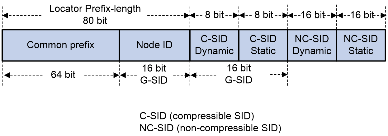

|
Device |
Interface |
IP address |
Device |
Interface |
IP address |
|
CE 1 |
XGE0/0/15 |
10.1.1.1/30 |
CE 2 |
XGE0/0/16 |
20.1.1.1/30 |
|
|
Loop0 |
11.11.11.11/32 |
|
Loop0 |
22.22.22.22/32 |
|
PE 1 |
Loop0 |
1::1/128 |
PE 2 |
Loop0 |
5::5/128 |
|
|
XGE0/0/15 |
10.1.1.2/30 |
|
XGE0/0/16 |
20.1.1.2/30 |
|
|
XGE0/0/16 |
12:1:1::1/126 |
|
XGE0/0/15 |
45:1:1::2/126 |
|
P 1 |
Loop0 |
2::2/128 |
P 2 |
Loop0 |
3::3/128 |
|
|
XGE0/0/15 |
23:1:1::1/126 |
|
XGE0/0/15 |
23:1:1::2/126 |
|
|
XGE0/0/16 |
12:1:1::2/126 |
|
XGE0/0/16 |
34:1:1::1/126 |
|
P 3 |
Loop0 |
4::4/128 |
|
|
|
|
|
XGE0/0/15 |
45:1:1::1/126 |
|
|
|
|
|
XGE0/0/16 |
34:1:1::2/126 |
|
|
|
Procedures
1. Configuring CE 1
# Configure IP addresses for the interfaces.
<CE1> system-view
[CE1] sysname CE1
[CE1] interface ten-gigabitethernet 0/0/15
[CE1-Ten-GigabitEthernet0/0/15] ip address 10.1.1.1 30
[CE1-Ten-GigabitEthernet0/0/15] quit
[CE1] interface loopback 0
[CE1-LoopBack0] ip address 11.11.11.11 32
[CE1-LoopBack0] quit
# Create EBGP peers between the PE and CE, and import direct routes.
[CE1] bgp 10
[CE1-bgp-default] router-id 11.11.11.11
[CE1-bgp-default] peer 10.1.1.2 as-number 100
[CE1-bgp-default] address-family ipv4 unicast
[CE1-bgp-default-ipv4] peer 10.1.1.2 enable
[CE1-bgp-default-ipv4] import-route direct
[CE1-bgp-default-ipv4] quit
[CE1-bgp-default] quit
2. Configuring CE 2
# Configure IP addresses for the interfaces.
<CE2> system-view
[CE2] sysname CE2
[CE2] interface ten-gigabitethernet 0/0/16
[CE2-Ten-GigabitEthernet0/0/16] ip address 20.1.1.1 30
[CE2-Ten-GigabitEthernet0/0/16] quit
[CE2] interface loopback 0
[CE2-LoopBack0] ip address 22.22.22.22 32
[CE2-LoopBack0] quit
# Create EBGP peers between the PE and CE, and import direct routes.
[CE2] bgp 20
[CE2-bgp-default] router-id 22.22.22.22
[CE2-bgp-default] peer 20.1.1.2 as-number 100
[CE2-bgp-default] address-family ipv4 unicast
[CE2-bgp-default-ipv4] peer 20.1.1.2 enable
[CE2-bgp-default-ipv4] import-route direct
[CE2-bgp-default-ipv4] quit
[CE2-bgp-default] quit
3. Configuring PE 1
# Configure the VPN instance on PE 1 to connect the CE to PE.
<PE1> system-view
[PE1] sysname PE1
[PE1] ip vpn-instance aaa
[PE1-vpn-instance-aaa] route-distinguisher 100:1
[PE1-vpn-instance-aaa] vpn-target 200:1 both
[PE1-vpn-instance-aaa] quit
# Configure IP addresses for the interfaces.
[PE1] interface loopback 0
[PE1-LoopBack0] ipv6 address 1::1 128
[PE1-LoopBack0] quit
[PE1] interface ten-gigabitethernet 0/0/15
[PE1-Ten-GigabitEthernet0/0/15] ip binding vpn-instance aaa
[PE1-Ten-GigabitEthernet0/0/15] ip address 10.1.1.2 30
[PE1-Ten-GigabitEthernet0/0/15] quit
[PE1] interface ten-gigabitethernet 0/0/16
[PE1-Ten-GigabitEthernet0/0/16] ipv6 address 12:1:1::1 126
[PE1-Ten-GigabitEthernet0/0/16] quit
# Configure IPv6 IS-IS to implement backbone network intercommunication.
[PE1] isis 1
[PE1-isis-1] is-level level-2
[PE1-isis-1] cost-style wide
[PE1-isis-1] network-entity 00.0000.0000.0001.00
[PE1-isis-1] address-family ipv6 unicast
[PE1-isis-1-ipv6] quit
[PE1-isis-1] quit
[PE1] interface ten-gigabitethernet 0/0/16
[PE1-Ten-GigabitEthernet0/0/16] isis ipv6 enable 1
[PE1-Ten-GigabitEthernet0/0/16] quit
[PE1] interface loopback 0
[PE1-LoopBack0] isis ipv6 enable 1
[PE1-LoopBack0] quit
# Configure an SRv6 locator on the PE, and enable SRv6 compression.
[PE1] segment-routing ipv6
[PE1-segment-routing-ipv6] srv6 compress enable
[PE1-segment-routing-ipv6] locator ax ipv6-prefix A:2:2:A:1:: 80 compress-16 non-compress-static 16 static 8
# Configure static compressible End.X SIDs on the PE.
[PE1-segment-routing-ipv6-locator-ax] opcode 32 end-x interface ten-gigabitethernet 0/0/16 nexthop 12:1:1::2 compress coc-next
[PE1-segment-routing-ipv6-locator-ax] quit
[PE1-segment-routing-ipv6] quit
# Execute the display segment-routing ipv6 local-sid end-x command to identify whether the configured static compressible End.X SIDs are successfully allocated, and examine the value for the 16-bit C-SID portion in the End.X SIDs. Note that the value range for the highest 4 bits of a 16-bit G-SID in the LIB is fixed at 0xE to 0xF.
[PE1] display segment-routing ipv6 local-sid end-x
Local SID forwarding table (End.X)
Total SIDs: 5
SID : A:2:2:A:1:E020::/80
Function type : End.X Flavor : COC,NEXT
Locator name : ax Allocation type: Static
Flag : - State : Active
Owner : SIDMGR Paths : 1
Path Index : 0
Interface : 错误!未提供文档变量。 Interface index: 0x2
Next hop : 12:1:1::2 Weight : 1
Create Time : Feb 10 11:22:17.360 2025
…
# Configure IS-IS to advertise the compressible SRv6 locator, and enable SRv6 compression.
[PE1] isis 1
[PE1-isis-1] address-family ipv6 unicast
[PE1-isis-1-ipv6] segment-routing ipv6 locator ax
[PE1-isis-1-ipv6] srv6 compress enable
[PE1-isis-1-ipv6] quit
[PE1-isis-1] quit
# Specify a source address for the outer IPv6 header of SRv6-encapsulated IP L3VPN packets on the PE.
[PE1] segment-routing ipv6
[PE1-segment-routing-ipv6] encapsulation source-address 1::1
# Configure the source address of SBFD packets on PE 1.
[PE1] sbfd source-ipv6 1::1
# Configure a static SID list on the PE, specify the static SID list for an SRv6 TE policy, and enable SBFD for the SRv6 TE policy, ensuring that the SRv6 TE policy tunnel can forward services correctly.
In the static SID list:
¡ The first hop is the End.X SID of the link from PE 1 to P 1. The End.X SID carries the COC&NEXT flavor. When the SRv6 packet is encapsulated, the 16-bit C-SID portion in the End.X SID is encapsulated in the packet to implement G-SID compression, and the next SID will continue to be compressed.
¡ The second hop is the End SID of P 2. This SID carries the COC&NEXT flavor. The 16-bit Node ID in the End SID is encapsulated in the SRv6 packet, and the next SID will continue to be compressed.
¡ The third hop is the End SID of P 3. The SID carries the COC&NEXT flavor. The 16-bit Node ID in the End SID is encapsulated in the SRv6 packet, and the next SID will continue to be compressed.
¡ The fourth hop is the End SID of PE 2. This SID carries the COC&NEXT flavor. The 16-bit Node ID in the End SID is encapsulated in the SRv6 packet. The next SID is an End.DT4 SID assigned by BGP to VPN routes, which can also be compressed.
¡ When encapsulating the compressed SRv6 packet, the device encapsulates the following items in sequence in the destination IPv6 address: 64-bit common prefix, first-hop 16-bit C-SID, second-hop 16-bit Node ID, third-hop 16-bit Node ID, and fourth-hop 16-bit Node ID. The total length of the previous items is 128 bits. The End.DT4 SID assigned by BGP to VPN routes is encapsulated in SID[0] of the SID list in the SRH.
[PE1] segment-routing ipv6
[PE1-segment-routing-ipv6] traffic-engineering
[PE1-srv6-te] srv6-policy locator ax
[PE1-srv6-te] segment-list b
[PE1-srv6-te-sl-b] index 10 compress-16 ipv6 A:2:2:A:E020:: block 64 node-length 0 function-length 16 compress-flavor coc-next
[PE1-srv6-te-sl-b] index 20 compress-16 ipv6 A:2:2:A:3:: block 64 node-length 16 function-length 0 compress-flavor coc-next
[PE1-srv6-te-sl-b] index 30 compress-16 ipv6 A:2:2:A:4:: block 64 node-length 16 function-length 0 compress-flavor coc-next
[PE1-srv6-te-sl-b] index 40 compress-16 ipv6 A:2:2:A:5:: block 64 node-length 16 function-length 0 compress-flavor coc-next
[PE1-srv6-te-sl-b] quit
[PE1-srv6-te] policy a
[PE1-srv6-te-policy-a] color 10 end-point ipv6 5::5
[PE1-srv6-te-policy-a] sbfd enable remote 1000001
[PE1-srv6-te-policy-a] candidate-paths
[PE1-srv6-te-policy-a-path] preference 200
[PE1-srv6-te-policy-a-path-pref-200] explicit segment-list b
[PE1-srv6-te-policy-a-path-pref-200] quit
[PE1-srv6-te-policy-a-path] quit
[PE1-srv6-te-policy-a] quit
[PE1-srv6-te] quit
[PE1-segment-routing-ipv6] quit
# Create EBGP peers between the PE and CE, and import VPN routes.
[PE1] bgp 100
[PE1-bgp-default] router-id 1.1.1.1
[PE1-bgp-default] ip vpn-instance aaa
[PE1-bgp-default-aaa] peer 10.1.1.1 as-number 10
[PE1-bgp-default-aaa] address-family ipv4 unicast
[PE1-bgp-default-ipv4-aaa] peer 10.1.1.1 enable
[PE1-bgp-default-ipv4-aaa] quit
[PE1-bgp-default-aaa] quit
# Create MP-IBGP peers between PE 1 and PE 2.
[PE1-bgp-default] peer 5::5 as-number 100
[PE1-bgp-default] peer 5::5 connect-interface loopback 0
[PE1-bgp-default] address-family vpnv4
[PE1-bgp-default-vpnv4] peer 5::5 enable
[PE1-bgp-default-vpnv4] quit
[PE1-bgp-default] quit
# Enable exchange of VPNv4 routes between MP-IBGP peers on PE 1, and enable recursion of VPN routes to the SRv6 TE policy tunnel.
[PE1] bgp 100
[PE1-bgp-default] address-family vpnv4
[PE1-bgp-default-vpnv4] peer 5::5 prefix-sid
[PE1-bgp-default-vpnv4] quit
[PE1-bgp-default] ip vpn-instance aaa
[PE1-bgp-default-aaa] address-family ipv4 unicast
[PE1-bgp-default-ipv4-aaa] segment-routing ipv6 locator ax compress-16
[PE1-bgp-default-ipv4-aaa] segment-routing ipv6 traffic-engineering
[PE1-bgp-default-ipv4-aaa] segment-routing ipv6 apply-sid compress coc-next
[PE1-bgp-default-ipv4-aaa] quit
[PE1-bgp-default-aaa] quit
[PE1-bgp-default] quit
# Configure a routing policy and a tunnel policy on PE 1 to steer VPN service traffic to the specified SRv6 TE policy through the routing policy and ensure that the SRv6 TE policy is the optimal tunnel.
[PE1] route-policy a permit node 10
[PE1-route-policy-a-10] apply extcommunity color 00:10
[PE1-route-policy-a-10] quit
[PE1] bgp 100
[PE1-bgp-default] address-family vpnv4
[PE1-bgp-default-vpnv4] peer 5::5 route-policy a import
[PE1-bgp-default-vpnv4] quit
[PE1-bgp-default] quit
[PE1] tunnel-policy a
[PE1-tunnel-policy-a] select-seq srv6-policy load-balance-number 1
[PE1-tunnel-policy-a] quit
[PE1] ip vpn-instance vpn1
[PE1-vpn-instance-vpn1] tnl-policy a
[PE1-vpn-instance-vpn1] quit
4. Configure P 1:
# Configure IP addresses for the interfaces.
[P1] interface loopback 0
[P1-LoopBack0] ipv6 address 2::2 128
[P1-LoopBack0] quit
[P1] interface ten-gigabitethernet 0/0/15
[P1-Ten-GigabitEthernet0/0/15] ipv6 address 23:1:1::1 126
[P1-Ten-GigabitEthernet0/0/15] quit
[P1] interface ten-gigabitethernet 0/0/16
[P1-Ten-GigabitEthernet0/0/16] ipv6 address 12:1:1::2 126
[P1-Ten-GigabitEthernet0/0/16] quit
# Configure IPv6 IS-IS to implement backbone network intercommunication.
[P1] isis 1
[P1-isis-1] is-level level-2
[P1-isis-1] cost-style wide
[P1-isis-1] network-entity 00.0000.0000.0002.00
[P1-isis-1] address-family ipv6 unicast
[P1-isis-1-ipv6] quit
[P1-isis-1] quit
[P1] interface ten-gigabitethernet 0/0/15
[P1-Ten-GigabitEthernet0/0/15] isis ipv6 enable 1
[P1-Ten-GigabitEthernet0/0/15] quit
[P1] interface ten-gigabitethernet 0/0/16
[P1-Ten-GigabitEthernet0/0/16] isis ipv6 enable 1
[P1-Ten-GigabitEthernet0/0/16] quit
[P1] interface loopback 0
[P1-LoopBack0] isis ipv6 enable 1
[P1-LoopBack0] quit
# Configure an SRv6 locator on P 1 to be advertised by IGP, and enable SRv6 compression.
[P1] segment-routing ipv6
[P1-segment-routing-ipv6] srv6 compress enable
[P1-segment-routing-ipv6] locator bx ipv6-prefix A:2:2:A:2:: 80 compress-16 non-compress-static 16 static 8
[P1-segment-routing-ipv6-locator-bx] quit
[P1-segment-routing-ipv6] quit
[P1] isis 1
[P1-isis-1] address-family ipv6 unicast
[P1-isis-1-ipv6] segment-routing ipv6 locator bx
[P1-isis-1-ipv6] srv6 compress enable
[P1-isis-1-ipv6] quit
[P1-isis-1] quit
5. Configure P 2:
# Configure IP addresses for the interfaces.
[P2] interface loopback 0
[P2-LoopBack0] ipv6 address 3::3 128
[P2-LoopBack0] quit
[P2] interface ten-gigabitethernet 0/0/15
[P2-Ten-GigabitEthernet0/0/15] ipv6 address 23:1:1::2 126
[P2-Ten-GigabitEthernet0/0/15] quit
[P2] interface ten-gigabitethernet 0/0/16
[P2-Ten-GigabitEthernet0/0/16] ipv6 address 34:1:1::1 126
[P2-Ten-GigabitEthernet0/0/16] quit
# Configure IPv6 IS-IS to implement backbone network intercommunication.
[P2] isis 1
[P2-isis-1] is-level level-2
[P2-isis-1] cost-style wide
[P2-isis-1] network-entity 00.0000.0000.0003.00
[P2-isis-1] address-family ipv6 unicast
[P2-isis-1-ipv6] quit
[P2-isis-1] quit
[P2] interface ten-gigabitethernet 0/0/15
[P2-Ten-GigabitEthernet0/0/15] isis ipv6 enable 1
[P2-Ten-GigabitEthernet0/0/15] quit
[P2] interface ten-gigabitethernet 0/0/16
[P2-Ten-GigabitEthernet0/0/16] isis ipv6 enable 1
[P2-Ten-GigabitEthernet0/0/16] quit
[P2] interface loopback 0
[P2-LoopBack0] isis ipv6 enable 1
[P2-LoopBack0] quit
# Configure an SRv6 locator on P 2 to be advertised by IGP, and enable SRv6 compression.
[P2] segment-routing ipv6
[P2-segment-routing-ipv6] srv6 compress enable
[P2-segment-routing-ipv6] locator cx ipv6-prefix A:2:2:A:3:: 80 compress-16 non-compress-static 16 static 8
[P2-segment-routing-ipv6-locator-cx] quit
[P2-segment-routing-ipv6] quit
[P2] isis 1
[P2-isis-1] address-family ipv6 unicast
[P2-isis-1-ipv6] segment-routing ipv6 locator cx
[P2-isis-1-ipv6] srv6 compress enable
[P2-isis-1-ipv6] quit
[P2-isis-1] quit
6. Configure P 3:
# Configure IP addresses for the interfaces.
[P3] interface loopback 0
[P3-LoopBack0] ipv6 address 4::4 128
[P3-LoopBack0] quit
[P3] interface ten-gigabitethernet 0/0/15
[P3-Ten-GigabitEthernet0/0/15] ipv6 address 45:1:1::1 126
[P3-Ten-GigabitEthernet0/0/15] quit
[P3] interface ten-gigabitethernet 0/0/16
[P3-Ten-GigabitEthernet0/0/16] ipv6 address 34:1:1::2 126
[P3-Ten-GigabitEthernet0/0/16] quit
# Configure IPv6 IS-IS to implement backbone network intercommunication.
[P3] isis 1
[P3-isis-1] is-level level-2
[P3-isis-1] cost-style wide
[P3-isis-1] network-entity 00.0000.0000.0004.00
[P3-isis-1] address-family ipv6 unicast
[P3-isis-1-ipv6] quit
[P3-isis-1] quit
[P3] interface ten-gigabitethernet 0/0/15
[P3-Ten-GigabitEthernet0/0/15] isis ipv6 enable 1
[P3-Ten-GigabitEthernet0/0/15] quit
[P3] interface ten-gigabitethernet 0/0/16
[P3-Ten-GigabitEthernet0/0/16] isis ipv6 enable 1
[P3-Ten-GigabitEthernet0/0/16] quit
[P3] interface loopback 0
[P3-LoopBack0] isis ipv6 enable 1
[P3-LoopBack0] quit
# Configure an SRv6 locator on P 3 to be advertised by IGP, and enable SRv6 compression.
[P3] segment-routing ipv6
[P3-segment-routing-ipv6] srv6 compress enable
[P3-segment-routing-ipv6] locator dx ipv6-prefix A:2:2:A:4:: 80 compress-16 non-compress-static 16 static 8
[P3-segment-routing-ipv6-locator-dx] quit
[P3-segment-routing-ipv6] quit
[P3] isis 1
[P3-isis-1] address-family ipv6 unicast
[P3-isis-1-ipv6] segment-routing ipv6 locator dx auto-sid-coc-both coc32
[P3-isis-1-ipv6] srv6 compress enable
[P3-isis-1-ipv6] quit
[P3-isis-1] quit
7. Configuring PE 2
# Configure the VPN instance on PE 2 to connect the CE to PE.
<PE2> system-view
[PE2] sysname PE2
[PE2] ip vpn-instance aaa
[PE2-vpn-instance-aaa] route-distinguisher 100:1
[PE2-vpn-instance-aaa] vpn-target 200:1 both
[PE2-vpn-instance-aaa] quit
# Configure IP addresses for the interfaces.
[PE2] interface loopback 0
[PE2-LoopBack0] ipv6 address 5::5 128
[PE2-LoopBack0] quit
[PE2] interface ten-gigabitethernet 0/0/16
[PE2-Ten-GigabitEthernet0/0/16] ip binding vpn-instance aaa
[PE2-Ten-GigabitEthernet0/0/16] ip address 20.1.1.2 30
[PE2-Ten-GigabitEthernet0/0/16] quit
[PE2] interface ten-gigabitethernet 0/0/15
[PE2-Ten-GigabitEthernet0/0/15] ipv6 address 45:1:1::2 126
[PE2-Ten-GigabitEthernet0/0/15] quit
# Configure IPv6 IS-IS to implement backbone network intercommunication.
[PE2] isis 1
[PE2-isis-1] is-level level-2
[PE2-isis-1] cost-style wide
[PE2-isis-1] network-entity 00.0000.0000.0005.00
[PE2-isis-1] address-family ipv6 unicast
[PE2-isis-1-ipv6] quit
[PE2-isis-1] quit
[PE2] interface ten-gigabitethernet 0/0/15
[PE2-Ten-GigabitEthernet0/0/15] isis ipv6 enable 1
[PE2-Ten-GigabitEthernet0/0/15] quit
[PE2] interface loopback 0
[PE2-LoopBack0] isis ipv6 enable 1
[PE2-LoopBack0] quit
# Configure an SRv6 locator on the PE to be advertised by IGP, and enable SRv6 compression.
[PE2] segment-routing ipv6
[PE2-segment-routing-ipv6] srv6 compress enable
[PE2-segment-routing-ipv6] locator ex ipv6-prefix A:2:2:A:5:: 80 compress-16 non-compress-static 16 static 8
[PE2-segment-routing-ipv6-locator-ex] quit
[PE2-segment-routing-ipv6] quit
[PE2] isis 1
[PE2-isis-1] address-family ipv6 unicast
[PE2-isis-1-ipv6] segment-routing ipv6 locator ex
[PE2-isis-1-ipv6] srv6 compress enable
[PE2-isis-1-ipv6] quit
[PE2-isis-1] quit
# Specify a source address for the outer IPv6 header of SRv6-encapsulated EVPN L3VPN packets on the PE.
[PE2] segment-routing ipv6
[PE2-segment-routing-ipv6] encapsulation source-address 5::5
# Create EBGP peers between the PE and CE, and import VPN routes.
[PE2] bgp 100
[PE2-bgp-default] router-id 5.5.5.5
[PE2-bgp-default] ip vpn-instance aaa
[PE2-bgp-default-aaa] peer 20.1.1.1 as-number 20
[PE2-bgp-default-aaa] address-family ipv4 unicast
[PE2-bgp-default-ipv4-aaa] peer 20.1.1.1 enable
[PE2-bgp-default-ipv4-aaa] quit
[PE2-bgp-default-aaa] quit
# Create MP-IBGP peers between PE 1 and PE 2.
[PE2-bgp-default] peer 1::1 as-number 100
[PE2-bgp-default] peer 1::1 connect-interface loopback 0
[PE2-bgp-default] address-family vpnv4
[PE2-bgp-default-vpnv4] peer 1::1 enable
[PE2-bgp-default-vpnv4] quit
[PE2-bgp-default] quit
# Enable exchange of VPNv4 routes between MP-IBGP peers on PE 2, and enable recursion of VPN routes to the SRv6 BE tunnel.
[PE2] bgp 100
[PE2-bgp-default] address-family vpnv4
[PE2-bgp-default-vpnv4] peer 1::1 prefix-sid
[PE2-bgp-default-vpnv4] quit
[PE2-bgp-default] ip vpn-instance aaa
[PE2-bgp-default-aaa] address-family ipv4 unicast
[PE2-bgp-default-ipv4-aaa] segment-routing ipv6 locator ex compress-16
[PE2-bgp-default-ipv4-aaa] segment-routing ipv6 apply-sid compress coc-next
[PE2-bgp-default-ipv4-aaa] segment-routing ipv6 best-effort
[PE2-bgp-default-ipv4-aaa] quit
[PE2-bgp-default-aaa] quit
[PE2-bgp-default] quit
# Specify the local discriminator for the SBFD session on PE 2, and make sure it is the same as the remote discriminator on PE 1.
[PE2] sbfd local-discriminator 1000001
Verifying the configuration
# On PE 1, execute the display segment-routing ipv6 te policy command to display detailed SRv6 TE policy information. Verify that the Status field for the SRv6 TE policy is Up, and the SID list state is Up.
<PE1> display segment-routing ipv6 te policy
Name/ID: a/0
Color: 10
End-point: 5::5
Name from BGP:
Name from PCE:
BSID:
Mode: Dynamic Type: Type_2 Request state: Succeeded
Current BSID: A:2:2:A:1:0:101:0 Explicit BSID: - Dynamic BSID: A:2:2:A:1:0:101:0
Reference counts: 5
Flags: A/BS/NC
Status: Up
AdminStatus: Up
Up time: 2023-08-06 16:31:34
Down time: 2023-08-06 16:29:20
…
Explicit SID list:
ID: 2 Name: b
Weight: 1 Forwarding index: 2149580805
State: Up State(SBFD): Up
Verification State: -
Path MTU: 1500 Path MTU Reserved: 0
SID list flags: None
Local BSID: -
Reverse BSID: -
# On PE 1, execute the display bgp routing-table vpnv4 command to display detailed information about the route sent by PE 2. Verify that the route sent by PE 2 carries the PrefixSID attribute data, and the route is recursed to SRv6 TE policy tunnel a.
<PE1> display bgp routing-table vpnv4 22.22.22.22
BGP local router ID: 1.1.1.1
Local AS number: 100
Route distinguisher: 100:1(aaa)
Total number of routes: 1
Paths: 1 available, 1 best
BGP routing table information of 22.22.22.22/32:
From : 5::5 (5.5.5.5)
Rely nexthop : FE80::1AF8:23FF:FE50:207
Original nexthop: 5::5
Out interface : Ten-GigabitEthernet0/0/16
Route age : 00h28m35s
OutLabel : 3
Ext-Community : <RT: 200:1>, <CO-Flag:Color(00:10)>
RxPathID : 0x0
TxPathID : 0x0
PrefixSID : End.DT4 SID <A:2:2:A:5:106:0:0>
SRv6 Service TLV (37 bytes):
Type: SRV6 L3 Service TLV (5)
Length: 34 bytes, Reserved: 0x0
SRv6 Service Information Sub-TLV (33 bytes):
Type: 1 Length: 30, Rsvdl: 0x0
SID Flags: 0x0 Endpoint behavior: 0x13 Rsvd2: 0x0
SRv6 SID Sub-Sub-TLV:
Type: 1 Len: 6
BL: 64 NL: 16 FL: 16 AL: 0 TL: 0 TO: 0
AS-path : 20
Origin : incomplete
Attribute value : MED 0, localpref 100, pref-val 0
State : valid, internal, best
Source type : local
IP precedence : N/A
QoS local ID : N/A
Traffic index : N/A
Tunnel policy : a
Rely tunnel IDs : 2150629378
# On PE 1, execute the display ip routing-table vpn-instance command. Verify that VPN route 22.22.22.22 is available to CE 2, and the output interface for the route is SRv6 TE policy tunnel a.
Take PE 1 as an example:
<PE1> display ip routing-table vpn-instance aaa
Destinations : 8 Routes : 8
Destination/Mask Proto Pre Cost NextHop Interface
10.1.1.0/30 Direct 0 0 10.1.1.2 XGE0/0/15
10.1.1.2/32 Direct 0 0 127.0.0.1 XGE0/0/15
10.1.1.3/32 Direct 0 0 10.1.1.2 XGE0/0/15
11.11.11.11/32 BGP 255 0 10.1.1.1 XGE0/0/15
20.1.1.0/30 BGP 255 0 5::5 a
22.22.22.22/32 BGP 255 0 5::5 a
127.0.0.0/8 Direct 0 0 127.0.0.1 InLoop0
255.255.255.255/32 Direct 0 0 127.0.0.1 InLoop0
# From source IP address 11.11.11.11 on CE 1, ping destination IP address 22.22.22.22 on CE 2. Verify that the ping operation is successful. Capture packets on the forwarding interfaces of the devices such as PE 1 to verify that the second-, third-, and fourth-hop SIDs are all compressed to 16 bits in the static SID list of the SRH. Compression is implemented through G-SRv6.
Example: Configuring IPv4 L3VPN HoVPN over MPLS-to-SRv6
Network configuration
As shown in Figure 21, the network between the UPE and MPE is an MPLS network and the network between the MPE and SPE is an SRv6 network. Configure HoVPN to permit users in the same VPN instance to communicate with each other across the MPLS and SRv6 networks.
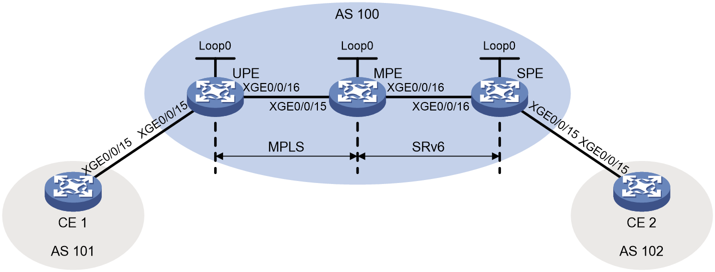
|
Device |
Interface |
IP address |
Device |
Interface |
IP address |
|
CE 1 |
XGE0/0/15 |
10.1.1.2/24 |
MPE |
Loop0 |
2.2.2.2/32 2::2/128 |
|
CE 2 |
XGE0/0/15 |
10.2.1.2/24 |
|
XGE0/0/15 |
11.1.1.2/24 |
|
UPE |
Loop0 |
1.1.1.1/32 |
|
XGE0/0/16 |
100::1/96 |
|
|
XGE0/0/15 |
10.1.1.1/24 |
SPE |
Loop0 |
3::3/128 |
|
|
XGE0/0/16 |
11.1.1.1/24 |
|
XGE0/0/15 |
10.2.1.1/24 |
|
|
|
|
|
XGE0/0/16 |
100::2/96 |
Procedure
1. Configure CE 1:
# Establish EBGP peer relationship with the UPE and import VPN routes.
<CE1> system-view
[CE1] bgp 101
[CE1-bgp-default] peer 10.1.1.1 as-number 100
[CE1-bgp-default] address-family ipv4 unicast
[CE1-bgp-default-ipv4] peer 10.1.1.1 enable
[CE1-bgp-default-ipv4] import-route direct
[CE1-bgp-default-ipv4] quit
[CE1-bgp-default] quit
2. Configure the UPE:
# Configure MPLS basic capability and MPLS LDP capability.
<UPE> system-view
[UPE] mpls lsr-id 1.1.1.1
[UPE] mpls ldp
[UPE-ldp] quit
# Configure IS-IS for backbone network communication.
[UPE] isis 1
[UPE-isis-1] is-level level-1
[UPE-isis-1] cost-style wide
[UPE-isis-1] network-entity 10.1111.1111.1111.00
[UPE-isis-1] quit
[UPE] interface loopback 0
[UPE-LoopBack0] ip address 1.1.1.1 32
[UPE-LoopBack0] isis enable 1
[UPE-LoopBack0] quit
[UPE] interface ten-gigabitethernet 0/0/16
[UPE-Ten-GigabitEthernet0/0/16] ip address 11.1.1.1 24
[UPE-Ten-GigabitEthernet0/0/16] isis enable 1
[UPE-Ten-GigabitEthernet0/0/16] mpls enable
[UPE-Ten-GigabitEthernet0/0/16] mpls ldp enable
[UPE-Ten-GigabitEthernet0/0/16] quit
# Configure a VPN instance for CE 1 to access the UPE.
[UPE] ip vpn-instance vpn1
[UPE-vpn-instance-vpn1] route-distinguisher 100:1
[UPE-vpn-instance-vpn1] vpn-target 111:1
[UPE-vpn-instance-vpn1] quit
[UPE] interface ten-gigabitethernet 0/0/15
[UPE-Ten-GigabitEthernet0/0/15] ip binding vpn-instance vpn1
[UPE-Ten-GigabitEthernet0/0/15] ip address 10.1.1.1 24
[UPE-Ten-GigabitEthernet0/0/15] quit
# Establish EBGP peer relationship with CE 1 and import VPN routes.
[UPE] bgp 100
[UPE-bgp-default] router-id 1.1.1.1
[UPE-bgp-default] ip vpn-instance vpn1
[UPE-bgp-default-vpn1] peer 10.1.1.2 as-number 101
[UPE-bgp-default-vpn1] address-family ipv4 unicast
[UPE-bgp-default-ipv4-vpn1] peer 10.1.1.2 enable
[UPE-bgp-default-ipv4-vpn1] import-route direct
[UPE-bgp-default-ipv4-vpn1] quit
[UPE-bgp-default-vpn1] quit
# Establish MP-IBGP peer relationship with the MPE.
[UPE-bgp-default] peer 2.2.2.2 as-number 100
[UPE-bgp-default] peer 2.2.2.2 connect-interface loopback 0
[UPE-bgp-default] address-family vpnv4
[UPE-bgp-default-vpnv4] peer 2.2.2.2 enable
[UPE-bgp-default-vpnv4] quit
[UPE-bgp-default] quit
3. Configure the MPE:
# Configure MPLS basic capability and MPLS LDP capability.
<MPE> system-view
[MPE] mpls lsr-id 2.2.2.2
[MPE] mpls ldp
[MPE-ldp] quit
# Configure IS-IS for backbone network communication.
[MPE] isis 1
[MPE-isis-1] is-level level-1
[MPE-isis-1] cost-style wide
[MPE-isis-1] network-entity 10.2222.2222.2222.00
[MPE-isis-1] address-family ipv6 unicast
[MPE-isis-1-ipv6] quit
[MPE-isis-1] quit
[MPE] interface loopback 0
[MPE-LoopBack0] ip address 2.2.2.2 32
[MPE-LoopBack0] ipv6 address 2::2 128
[MPE-LoopBack0] isis enable 1
[MPE-LoopBack0] isis ipv6 enable 1
[MPE-LoopBack0] quit
[MPE] interface ten-gigabitethernet 0/0/15
[MPE-Ten-GigabitEthernet0/0/15] ip address 11.1.1.2 24
[MPE-Ten-GigabitEthernet0/0/15] isis enable 1
[MPE-Ten-GigabitEthernet0/0/15] mpls enable
[MPE-Ten-GigabitEthernet0/0/15] mpls ldp enable
[MPE-Ten-GigabitEthernet0/0/15] quit
[MPE] interface ten-gigabitethernet 0/0/16
[MPE-Ten-GigabitEthernet0/0/16] ipv6 address 100::1 96
[MPE-Ten-GigabitEthernet0/0/16] isis ipv6 enable 1
[MPE-Ten-GigabitEthernet0/0/16] quit
# Configure a VPN instance.
[MPE] ip vpn-instance vpn2
[MPE-vpn-instance-vpn1] route-distinguisher 200:1
[MPE-vpn-instance-vpn1] vpn-target 111:1
[MPE-vpn-instance-vpn1] quit
# Establish MP-IBGP peer relationship with the UPE and SPE.
[MPE] bgp 100
[MPE-bgp-default] router-id 2.2.2.2
[MPE-bgp-default] peer 1.1.1.1 as-number 100
[MPE-bgp-default] peer 1.1.1.1 connect-interface LoopBack0
[MPE-bgp-default] peer 3::3 as-number 100
[MPE-bgp-default] peer 3::3 connect-interface LoopBack0
[MPE-bgp-default] address-family vpnv4
[MPE-bgp-default-vpnv4] peer 1.1.1.1 enable
[MPE-bgp-default-vpnv4] peer 3::3 enable
[MPE-bgp-default-vpnv4] quit
# Specify a UPE.
[MPE-bgp-default-vpnv4] peer 1.1.1.1 upe
[MPE-bgp-default-vpnv4] peer 1.1.1.1 next-hop-local
# Configure optimal route reorigination and advertisement for intercommunication between the MPLS L3VPN network and IP L3VPN over SRv6 network.
[MPE-bgp-default] ip vpn-instance vpn2
[MPE-bgp-default-vpn2] address-family ipv4 unicast
[MPE-bgp-default-ipv4-vpn2] advertise route-reoriginate
[MPE-bgp-default-ipv4-vpn2] quit
[MPE-bgp-default-vpn2] quit
[MPE-bgp-default] quit
# Enable the MPE to send routing information matching a routing policy to the UPE. The route of CE 2 can be sent to the UPE.
[MPE] ip prefix-list hovpn index 10 permit 10.2.1.0 24
[MPE] route-policy hovpn permit node 0
[MPE-route-policy-hovpn-0] if-match ip address prefix-list hovpn
[MPE-route-policy-hovpn-0] quit
[MPE] bgp 100
[MPE-bgp-default] address-family vpnv4
[MPE-bgp-default-vpnv4] peer 1.1.1.1 upe route-policy hovpn export
[MPE-bgp-default-vpnv4] quit
[MPE-bgp-default] quit
# Configure L3VPN over SRv6 BE.
[MPE] segment-routing ipv6
[MPE-segment-routing-ipv6] encapsulation source-address 2::2
[MPE-segment-routing-ipv6] locator hovpn ipv6-prefix 42:1:: 64 static 32
[MPE-segment-routing-ipv6-locator-hovpn] quit
[MPE-segment-routing-ipv6] quit
[MPE] bgp 100
[MPE-bgp-default] address-family vpnv4
[MPE-bgp-default-vpnv4] peer 3::3 prefix-sid
[MPE-bgp-default-vpnv4] quit
[MPE-bgp-default] ip vpn-instance vpn2
[MPE-bgp-default-vpn2] address-family ipv4 unicast
[MPE-bgp-default-ipv4-vpn2] segment-routing ipv6 best-effort
[MPE-bgp-default-ipv4-vpn2] segment-routing ipv6 locator hovpn
[MPE-bgp-default-ipv4-vpn2] quit
[MPE-bgp-default-vpn2] quit
[MPE-bgp-default] quit
[MPE] isis 1
[MPE-isis-1] address-family ipv6 unicast
[MPE-isis-1-ipv6] segment-routing ipv6 locator hovpn
[MPE-isis-1-ipv6] quit
[MPE-isis-1] quit
4. Configure the SPE:
# Configure IPv6 IS-IS for backbone network communication.
<SPE> system-view
[SPE] isis 1
[SPE-isis-1] is-level level-1
[SPE-isis-1] cost-style wide
[SPE-isis-1] network-entity 10.3333.3333.3333.00
[SPE-isis-1] address-family ipv6 unicast
[SPE-isis-1-ipv6] quit
[SPE-isis-1] quit
[SPE] interface loopback 0
[SPE-LoopBack0] ipv6 address 3::3 128
[SPE-LoopBack0] isis ipv6 enable 1
[SPE-LoopBack0] quit
[SPE] interface ten-gigabitethernet 0/0/16
[SPE-Ten-GigabitEthernet0/0/16] ipv6 address 100::2 96
[SPE-Ten-GigabitEthernet0/0/16] isis ipv6 enable 1
[SPE-Ten-GigabitEthernet0/0/16] quit
# Configure a VPN instance for CE 2 to access the SPE.
[SPE] ip vpn-instance vpn1
[SPE-vpn-instance-vpn1] route-distinguisher 100:1
[SPE-vpn-instance-vpn1] vpn-target 111:1
[SPE-vpn-instance-vpn1] quit
[SPE] interface ten-gigabitethernet 0/0/15
[SPE-Ten-GigabitEthernet0/0/15] ip binding vpn-instance vpn1
[SPE-Ten-GigabitEthernet0/0/15] ip address 10.2.1.1 24
[SPE-Ten-GigabitEthernet0/0/15] quit
# Establish EGFP peer relationship with CE 2 and import VPN routes.
[SPE] bgp 100
[SPE-bgp-default] router-id 3.3.3.3
[SPE-bgp-default] ip vpn-instance vpn1
[SPE-bgp-default-vpn1] peer 10.2.1.2 as-number 102
[SPE-bgp-default-vpn1] address-family ipv4 unicast
[SPE-bgp-default-ipv4-vpn1] peer 10.2.1.2 enable
[SPE-bgp-default-ipv4-vpn1] import-route direct
[SPE-bgp-default-ipv4-vpn1] quit
[SPE-bgp-default-vpn1] quit
# Establish MP-IBGP peer relationship with the MPE.
[SPE] bgp 100
[SPE-bgp-default] peer 2::2 as-number 100
[SPE-bgp-default] peer 2::2 connect-interface loopback 0
[SPE-bgp-default] address-family vpnv4
[SPE-bgp-default-vpnv4] peer 2::2 enable
[SPE-bgp-default-vpnv4] quit
[SPE-bgp-default] quit
# Configure L3VPN over SRv6 BE.
[SPE] segment-routing ipv6
[SPE-segment-routing-ipv6] encapsulation source-address 3::3
[SPE-segment-routing-ipv6] locator hovpn ipv6-prefix 43:1:: 64 static 32
[SPE-segment-routing-ipv6-locator-hovpn] quit
[SPE-segment-routing-ipv6] quit
[SPE] bgp 100
[SPE-bgp-default] address-family vpnv4
[SPE-bgp-default-vpnv4] peer 2::2 prefix-sid
[SPE-bgp-default-vpnv4] quit
[SPE-bgp-default] ip vpn-instance vpn1
[SPE-bgp-default-vpn1] address-family ipv4 unicast
[SPE-bgp-default-ipv4-vpn1] segment-routing ipv6 best-effort
[SPE-bgp-default-ipv4-vpn1] segment-routing ipv6 locator hovpn
[SPE-bgp-default-ipv4-vpn1] quit
[SPE-bgp-default-vpn1] quit
[SPE-bgp-default] quit
[SPE] isis 1
[SPE-isis-1] address-family ipv6 unicast
[SPE-isis-1-ipv6] segment-routing ipv6 locator hovpn
[SPE-isis-1-ipv6] quit
[SPE-isis-1] quit
5. Configure CE 2:
# Establish EBGP peer relationship with the SPE and import VPN routes.
<CE2> system-view
[CE2] bgp 102
[CE2-bgp-default] peer 10.2.1.1 as-number 100
[CE2-bgp-default] address-family ipv4 unicast
[CE2-bgp-default-ipv4] peer 10.2.1.1 enable
[CE2-bgp-default-ipv4] import-route direct
[CE2-bgp-default-ipv4] quit
[CE2-bgp-default] quit
Verifying the configuration
# On MPE, verify that the routes destined for CE 2 and CE 1 have established SRv6 SID and MPLS label mappings.
[MPE] display bgp routing-table vpnv4 10.2.1.0 24
BGP local router ID: 2.2.2.2
Local AS number: 100
Route distinguisher: 100:1
Total number of routes: 1
Paths: 1 available, 1 best
BGP routing table information of 10.2.1.0/24:
From : 3::3 (3.3.3.3)
Rely nexthop : FE80::9885:31FF:FE87:317
Original nexthop: 3::3
Out interface : Ten-GigabitEthernet0/0/16
Route age : 03h16m43s
OutLabel : 3
Ext-Community : <RT: 111:1>
RxPathID : 0x0
TxPathID : 0x0
PrefixSID : End.DT4 SID <43:1::1:0:2>
…
Route distinguisher: 200:1(vpn2)
Total number of routes: 1
Paths: 1 available, 1 best
BGP routing table information of 10.2.1.0/24:
From : 3::3 (3.3.3.3)
Rely nexthop : FE80::9885:31FF:FE87:317
Original nexthop: 3::3
Out interface : Ten-GigabitEthernet0/0/16
Route age : 03h16m43s
OutLabel : 3
Ext-Community : <RT: 111:1>
RxPathID : 0x0
TxPathID : 0x0
PrefixSID : End.DT4 SID <43:1::1:0:2>
…
[MPE] display bgp routing-table vpnv4 10.1.1.0 24
BGP local router ID: 2.2.2.2
Local AS number: 100
Route distinguisher: 100:1
Total number of routes: 1
Paths: 1 available, 1 best
BGP routing table information of 10.1.1.0/24:
From : 1.1.1.1 (1.1.1.1)
Rely nexthop : 11.1.1.1
Original nexthop: 1.1.1.1
Out interface : Ten-GigabitEthernet0/0/15
Route age : 00h44m22s
OutLabel : 600126
Ext-Community : <RT: 111:1>
RxPathID : 0x0
TxPathID : 0x0
…
Route distinguisher: 200:1(vpn2)
Total number of routes: 1
Paths: 1 available, 1 best
BGP routing table information of 10.1.1.0/24:
From : 1.1.1.1 (1.1.1.1)
Rely nexthop : 11.1.1.1
Original nexthop: 1.1.1.1
Out interface : Ten-GigabitEthernet0/0/15
Route age : 00h44m22s
OutLabel : 600126
Ext-Community : <RT: 111:1>
RxPathID : 0x0
TxPathID : 0x0
PrefixSID : End.DT4 SID <42:1::1:0:2>
…
# Verify that CE 1 and CE 2 can ping each other. (Details not shown.)
Example: Configuring inter-AS option B VPN
Network configuration
As shown in Figure 22, an MPLS network is deployed in AS 100 and an SRv6 network is deployed in AS 200. Configure inter-AS option B VPN to permit users in the same VPN instance to communicate with each other across the MPLS and SRv6 networks.
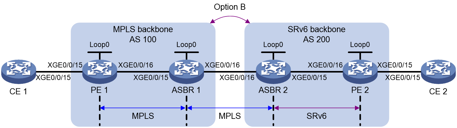
|
Device |
Interface |
IP address |
Device |
Interface |
IP address |
|
CE 1 |
XGE0/0/15 |
10.1.1.2/24 |
CE 2 |
XGE0/0/15 |
20.1.1.2/24 |
|
PE 1 |
Loop0 |
1.1.1.1/32 |
PE 2 |
Loop0 |
1::1/128 |
|
|
XGE0/0/15 |
10.1.1.1/24 |
|
XGE0/0/15 |
20.1.1.1/24 |
|
|
XGE0/0/16 |
11.1.1.1/24 |
|
XGE0/0/16 |
100::1/96 |
|
ASBR 1 |
Loop0 |
2.2.2.2/32 |
ASBR 2 |
Loop0 |
2::2/128 |
|
|
XGE0/0/15 |
11.1.1.2/24 |
|
XGE0/0/15 |
100::2/96 |
|
|
XGE0/0/16 |
12.1.1.1/24 |
|
XGE0/0/16 |
12.1.1.2/24 |
Procedure
1. Configure CE 1:
# Establish EBGP peer relationship with PE 1 and import VPN routes.
<CE1> system-view
[CE1] bgp 101
[CE1-bgp-default] peer 10.1.1.1 as-number 100
[CE1-bgp-default] address-family ipv4 unicast
[CE1-bgp-default-ipv4] peer 10.1.1.1 enable
[CE1-bgp-default-ipv4] import-route direct
[CE1-bgp-default-ipv4] quit
[CE1-bgp-default] quit
2. Configure PE 1:
# Run IS-IS on PE 1.
<PE1> system-view
[PE1] isis 1
[PE1-isis-1] cost-style wide
[PE1-isis-1] network-entity 10.1111.1111.1111.00
[PE1-isis-1] quit
# Specify an LSR ID and enable MPLS and LDP.
[PE1] mpls lsr-id 1.1.1.1
[PE1] mpls ldp
[PE1-ldp] quit
# On interface Ten-GigabitEthernet 0/0/16, specify an IP address, run IS-IS, and enable MPLS and LDP.
[PE1] interface ten-gigabitethernet 0/0/16
[PE1-Ten-GigabitEthernet0/0/16] ip address 11.1.1.1 255.0.0.0
[PE1-Ten-GigabitEthernet0/0/16] isis enable 1
[PE1-Ten-GigabitEthernet0/0/16] mpls enable
[PE1-Ten-GigabitEthernet0/0/16] mpls ldp enable
[PE1-Ten-GigabitEthernet0/0/16] quit
# Create interface Loopback 0, specify an IP address for the interface, and run IS-IS on the interface.
[PE1] interface loopback 0
[PE1-LoopBack0] ip address 1.1.1.1 32
[PE1-LoopBack0] isis enable 1
[PE1-LoopBack0] quit
# Create a VPN instance named vpn1 and configure a RD and route target for the VPN instance.
[PE1] ip vpn-instance vpn1
[PE1-vpn-instance-vpn1] route-distinguisher 100:1
[PE1-vpn-instance-vpn1] vpn-target 100:1
[PE1-vpn-instance-vpn1] quit
# Associate the interface connected to CE 1 with VPN instance vpn1.
[PE1] interface ten-gigabitethernet 0/0/15
[PE1-Ten-GigabitEthernet0/0/15] ip binding vpn-instance vpn1
[PE1-Ten-GigabitEthernet0/0/15] ip address 10.1.1.1 24
[PE1-Ten-GigabitEthernet0/0/15] quit
# Run BGP on PE 1.
[PE1] bgp 100
[PE1-bgp-default] router-id 1.1.1.1
# Configure IBGP peer 2.2.2.2 as a VPNv4 peer.
[PE1-bgp-default] peer 2.2.2.2 as-number 100
[PE1-bgp-default] peer 2.2.2.2 connect-interface loopback 0
[PE1-bgp-default] address-family vpnv4
[PE1-bgp-default-vpnv4] peer 2.2.2.2 enable
[PE1-bgp-default-vpnv4] quit
# Establish EBGP peer relationship with CE 1 and import VPN routes.
[PE1-bgp-default] ip vpn-instance vpn1
[PE1-bgp-default-vpn1] peer 10.1.1.2 as-number 101
[PE1-bgp-default-vpn1] address-family ipv4 unicast
[PE1-bgp-default-ipv4-vpn1] peer 10.1.1.2 enable
[PE1-bgp-default-ipv4-vpn1] quit
[PE1-bgp-default-vpn1] quit
3. Configure ASBR 1:
# Run IS-IS on ASBR 1.
<ASBR1> system-view
[ASBR1] isis 1
[ASBR1-isis-1] cost-style wide
[ASBR1-isis-1] network-entity 10.2222.2222.2222.00
[ASBR1-isis-1] quit
# Specify an LSR ID and enable MPLS and LDP.
[ASBR1] mpls lsr-id 2.2.2.2
[ASBR1] mpls ldp
[ASBR1-ldp] quit
# On interface Ten-GigabitEthernet 0/0/15, specify an IP address, run IS-IS, and enable MPLS and LDP.
[ASBR1] interface ten-gigabitethernet 0/0/15
[ASBR1-Ten-GigabitEthernet0/0/15] ip address 11.1.1.2 255.0.0.0
[ASBR1-Ten-GigabitEthernet0/0/15] isis enable 1
[ASBR1-Ten-GigabitEthernet0/0/15] mpls enable
[ASBR1-Ten-GigabitEthernet0/0/15] mpls ldp enable
[ASBR1-Ten-GigabitEthernet0/0/15] quit
# On interface Ten-GigabitEthernet 0/0/16, specify an IP address and enable MPLS.
[ASBR1] interface ten-gigabitethernet 0/0/16
[ASBR1-Ten-GigabitEthernet0/0/16] ip address 12.1.1.1 255.0.0.0
[ASBR1-Ten-GigabitEthernet0/0/16] mpls enable
[ASBR1-Ten-GigabitEthernet0/0/16] quit
# Create interface Loopback 0, specify an IP address and run IS-IS on the interface.
[ASBR1] interface loopback 0
[ASBR1-LoopBack0] ip address 2.2.2.2 32
[ASBR1-LoopBack0] isis enable 1
[ASBR1-LoopBack0] quit
# Run BGP on ASBR 1.
[ASBR1] bgp 100
[ASBR1-bgp-default] router-id 2.2.2.2
[ASBR1-bgp-default] peer 1.1.1.1 as-number 100
[ASBR1-bgp-default] peer 1.1.1.1 connect-interface loopback 0
[ASBR1-bgp-default] peer 12.1.1.2 as-number 200
[ASBR1-bgp-default] peer 12.1.1.2 connect-interface ten-gigabitethernet 0/0/16
# Configure BGP to not filter received VPNv4 routes based on route targets.
[ASBR1-bgp-default] address-family vpnv4
[ASBR1-bgp-default-vpnv4] undo policy vpn-target
# Configure IBGP peer 1.1.1.1 and EBGP peer 12.1.1.2 as VPNv4 peers.
[ASBR1-bgp-default-vpnv4] peer 12.1.1.2 enable
[ASBR1-bgp-default-vpnv4] peer 1.1.1.1 enable
[ASBR1-bgp-default-vpnv4] quit
[ASBR1-bgp-default] quit
4. Configure ASBR 2:
# Run IPv6 IS-IS on ASBR 2.
<ASBR2> system-view
[ASBR2] isis 1
[ASBR2-isis-1] cost-style wide
[ASBR2-isis-1] network-entity 10.3333.3333.3333.00
[ASBR2-isis-1] address-family ipv6 unicast
[ASBR2-isis-1-ipv6] quit
[ASBR2-isis-1] quit
# On interface Ten-GigabitEthernet 0/0/15, specify an IPv6 address and run IPv6 IS-IS.
[ASBR2] interface ten-gigabitethernet 0/0/15
[ASBR2-Ten-GigabitEthernet0/0/15] ipv6 address 100::2 96
[ASBR2-Ten-GigabitEthernet0/0/15] isis ipv6 enable 1
[ASBR2-Ten-GigabitEthernet0/0/15] quit
# On interface Ten-GigabitEthernet 0/0/16, specify an IP address and enable MPLS.
[ASBR2] interface ten-gigabitethernet 0/0/16
[ASBR2-Ten-GigabitEthernet0/0/16] ip address 12.1.1.2 255.0.0.0
[ASBR2-Ten-GigabitEthernet0/0/16] mpls enable
[ASBR2-Ten-GigabitEthernet0/0/16] quit
# Create interface Loopback 0, specify an IPv6 address for the interface, and run IPv6 IS-IS on the interface.
[ASBR2] interface loopback 0
[ASBR2-LoopBack0] ipv6 address 2::2 128
[ASBR2-LoopBack0] isis ipv6 enable 1
[ASBR2-LoopBack0] quit
# Run BGP on ASBR 2.
[ASBR2] bgp 200
[ASBR2-bgp-default] router-id 3.3.3.3
[ASBR2-bgp-default] peer 12.1.1.1 as-number 100
[ASBR2-bgp-default] peer 12.1.1.1 connect-interface ten-gigabitethernet 0/0/16
[ASBR2-bgp-default] peer 1::1 as-number 200
[ASBR2-bgp-default] peer 1::1 connect-interface loopback 0
# Configure BGP to not filter received VPNv4 routes based on route targets.
[ASBR2-bgp-default] address-family vpnv4
[ASBR2-bgp-default-vpnv4] undo policy vpn-target
# Configure IBGP peer 1::1 and EBGP peer 12.1.1.1 as VPNv4 peers.
[ASBR2-bgp-default-vpnv4] peer 12.1.1.1 enable
[ASBR2-bgp-default-vpnv4] peer 1::1 enable
[ASBR2-bgp-default-vpnv4] quit
[ASBR2-bgp-default] quit
# Configure L3VPN over SRv6 BE.
[ASBR2] segment-routing ipv6
[ASBR2-segment-routing-ipv6] encapsulation source-address 2::2
[ASBR2-segment-routing-ipv6] locator abc ipv6-prefix 43:1:: 64 static 32
[ASBR2-segment-routing-ipv6-locator-abc] quit
[ASBR2-segment-routing-ipv6] quit
[ASBR2] bgp 200
[ASBR2-bgp-default] address-family vpnv4
[ASBR2-bgp-default-vpnv4] segment-routing ipv6 best-effort
[ASBR2-bgp-default-vpnv4] segment-routing ipv6 locator abc
[ASBR2-bgp-default-vpnv4] peer 1::1 prefix-sid
# Enable SRv6 and MPLS interworking.
[ASBR2-bgp-default-vpnv4] srv6-mpls-interworking enable
[ASBR2-bgp-default-vpnv4] quit
[ASBR2-bgp-default] quit
# Apply a locator to IPv6 IS-IS.
[ASBR2] isis 1
[ASBR2-isis-1] address-family ipv6 unicast
[ASBR2-isis-1-ipv6] segment-routing ipv6 locator abc
[ASBR2-isis-1-ipv6] quit
[ASBR2-isis-1] quit
5. Configure PE 2:
# Run IPv6 IS-IS on PE 2.
<PE2> system-view
[PE2] isis 1
[PE2-isis-1] cost-style wide
[PE2-isis-1] network-entity 10.4444.4444.4444.00
[PE2-isis-1] address-family ipv6 unicast
[PE2-isis-1-ipv6] quit
[PE2-isis-1] quit
# On interface Ten-GigabitEthernet 0/0/16, specify an IPv6 address and run IPv6 IS-IS.
[PE2] interface ten-gigabitethernet 0/0/16
[PE2-Ten-GigabitEthernet0/0/16] ipv6 address 100::1 96
[PE2-Ten-GigabitEthernet0/0/16] isis ipv6 enable 1
[PE2-Ten-GigabitEthernet0/0/16] quit
# Create interface Loopback 0, specify an IPv6 address and run IPv6 IS-IS on the interface.
[PE2] interface loopback 0
[PE2-LoopBack0] ipv6 address 1::1 128
[PE2-LoopBack0] isis ipv6 enable 1
[PE2-LoopBack0] quit
# Create a VPN instance named vpn1 and configure a RD and route target for the VPN instance.
[PE2] ip vpn-instance vpn1
[PE2-vpn-instance-vpn1] route-distinguisher 100:1
[PE2-vpn-instance-vpn1] vpn-target 100:1
[PE2-vpn-instance-vpn1] quit
# Associate the interface connected to CE 2 with VPN instance vpn1.
[PE2] interface ten-gigabitethernet 0/0/15
[PE2-Ten-GigabitEthernet0/0/15] ip binding vpn-instance vpn1
[PE2-Ten-GigabitEthernet0/0/15] ip address 20.1.1.1 24
[PE2-Ten-GigabitEthernet0/0/15] quit
# Run BGP on PE 2.
[PE2] bgp 200
[PE2-bgp-default] router-id 4.4.4.4
# Configure IBGP peer 2::2 as a VPNv4 peer.
[PE2-bgp-default] peer 2::2 as-number 200
[PE2-bgp-default] peer 2::2 connect-interface loopback 0
[PE2-bgp-default] address-family vpnv4
[PE2-bgp-default-vpnv4] peer 2::2 enable
[PE2-bgp-default-vpnv4] quit
# Establish EBGP peer relationship with CE 2 and import VPN routes.
[PE2-bgp-default] ip vpn-instance vpn1
[PE2-bgp-default-vpn1] peer 20.1.1.2 as-number 201
[PE2-bgp-default-vpn1] address-family ipv4 unicast
[PE2-bgp-default-ipv4-vpn1] peer 20.1.1.2 enable
[PE2-bgp-default-ipv4-vpn1] quit
[PE2-bgp-default-vpn1] quit
# Configure L3VPN over SRv6 BE.
[PE2] segment-routing ipv6
[PE2-segment-routing-ipv6] encapsulation source-address 1::1
[PE2-segment-routing-ipv6] locator abc ipv6-prefix 42:1:: 64 static 32
[PE2-segment-routing-ipv6-locator-abc] quit
[PE2-segment-routing-ipv6] quit
[PE2] bgp 200
[PE2-bgp-default] ip vpn-instance vpn1
[PE2-bgp-default-vpn1] address-family ipv4 unicast
[PE2-bgp-default-ipv4-vpn1] segment-routing ipv6 best-effort
[PE2-bgp-default-ipv4-vpn1] segment-routing ipv6 locator abc
[PE2-bgp-default-ipv4-vpn1] quit
[PE2-bgp-default-vpn1] quit
[PE2-bgp-default] address-family vpnv4
[PE2-bgp-default-vpnv4] peer 2::2 prefix-sid
[PE2-bgp-default-vpnv4] quit
[PE2-bgp-default] quit
# Apply a locator to IPv6 IS-IS.
[PE2] isis 1
[PE2-isis-1] address-family ipv6 unicast
[PE2-isis-1-ipv6] segment-routing ipv6 locator abc
[PE2-isis-1-ipv6] quit
[PE2-isis-1] quit
6. Configure CE 2:
# Establish EBGP peer relationship with PE 2 and import VPN routes.
<CE2> system-view
[CE2] bgp 201
[CE2-bgp-default] peer 20.1.1.1 as-number 200
[CE2-bgp-default] address-family ipv4 unicast
[CE2-bgp-default-ipv4] peer 20.1.1.1 enable
[CE2-bgp-default-ipv4] import-route direct
[CE2-bgp-default-ipv4] quit
[CE2-bgp-default] quit
Verifying the configuration
# On ASBR 2, verify that the MPLS label and SRv6 SID have established mapping relationship. The LSP out label is the SRv6 SID.
[ASBR2] display mpls lsp srv6-mpls-interworking
FEC : 3::3/43:1::1:0:2
Protocol : BGP
In Label : 600127
Out SRv6 SID : 43:1::1:0:2
Path ID : 0x16000000.1
# On ASBR 2, verify that an End.T SID has been allocated to FEC 10.1.1.0/24.
[ASBR2] display bgp routing-table vpnv4 10.1.1.0
BGP local router ID: 3.3.3.3
Local AS number: 200
Route distinguisher: 100:1
Total number of routes: 1
Paths: 1 available, 1 best
BGP routing table information of 10.1.1.0/24:
From : 12.1.1.1 (2.2.2.2)
Rely nexthop : 12.1.1.1
Original nexthop: 12.1.1.1
Out interface : Ten-GigabitEthernet0/0/16
Route age : 00h03m18s
OutLabel : 600126
Ext-Community : <RT: 100:1>
RxPathID : 0x0
TxPathID : 0x0
PrefixSID : End.T SID <42:1::1:0:4>
AS-path : 100 101
Origin : incomplete
Attribute value : pref-val 0
State : valid, external, best
IP precedence : N/A
QoS local ID : N/A
Traffic index : N/A
Tunnel policy : NULL
Rely tunnel IDs : 1
# Verify that CE 1 and CE 2 can ping each other. (Details not shown.)
Example: Configuring SRv6 VPN Option B cross-AS intercommunication (carrying private network routes with the same route type)
Network configuration
As shown in Figure 23, AS 100 and AS 200 are two IP L3VPN over Srv6 networks deployed at different locations. CE 1 and CE 2 both belong to VPN instance vpn1 and connect to IPv4 users. To have users connected to CE 1 and CE 2 to access each other, configure SRv6 VPN Option B cross-AS intercommunication.
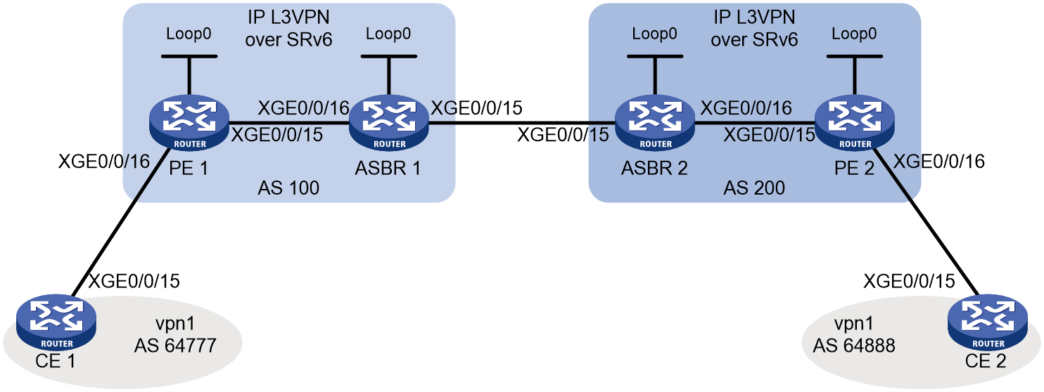
|
Device |
Interfaces |
IP address |
Device |
Interfaces |
IP address |
|
CE 1 |
XGE0/0/15 |
10.10.10.2/24 |
CE 2 |
XGE0/0/15 |
20.20.20.2/24 |
|
PE 1 |
Loop0 |
1::1/128 |
PE 2 |
Loop0 |
4::4/128 |
|
|
XGE0/0/15 |
2012::1/96 |
|
XGE0/0/15 |
2034::4/96 |
|
|
XGE0/0/16 |
10.10.10.1/24 |
|
XGE0/0/16 |
20.20.20.1/24 |
|
ASBR 1 |
Loop0 |
2::2/128 |
ASBR 2 |
Loop0 |
3::3/128 |
|
|
XGE0/0/15 |
2023::2/96 |
|
XGE0/0/15 |
2023::3/96 |
|
|
XGE0/0/16 |
2012::2/96 |
|
XGE0/0/16 |
2034::3/96 |
Procedure
1. Configure the IP address of each device interface. (Details not shown.)
2. Enable the CE and PE to exchange VPN routes
# Configure a VPN instance on PE 1 and connect CE 1 to PE 1.
<PE1> system-view
[PE1] ip vpn-instance vpn1
[PE1-vpn-instance-vpn1] route-distinguisher 1:1
[PE1-vpn-instance-vpn1] vpn-target 1:1
[PE1-vpn-instance-vpn1] quit
[PE1] interface ten-gigabitethernet 0/0/16
[PE1-Ten-GigabitEthernet0/0/16] ip binding vpn-instance vpn1
[PE1-Ten-GigabitEthernet0/0/16] ip address 10.10.10.1 24
[PE1-Ten-GigabitEthernet0/0/16] quit
# Configure a VPN instance on PE 2 and connect CE 2 to PE 2.
<PE2> system-view
[PE2] ip vpn-instance vpn1
[PE2-vpn-instance-vpn1] route-distinguisher 4:4
[PE2-vpn-instance-vpn1] vpn-target 1:1
[PE2-vpn-instance-vpn1] quit
[PE2] interface ten-gigabitethernet 0/0/16
[PE2-Ten-GigabitEthernet0/0/16] ip binding vpn-instance vpn1
[PE2-Ten-GigabitEthernet0/0/16] ip address 20.20.20.1 24
[PE2-Ten-GigabitEthernet0/0/16] quit
# Create EBGP peers between PE 1 and CE 1, and redistribute VPN routes to CE 1.
<CE1> system-view
[CE1] bgp 64777
[CE1-bgp-default] peer 10.10.10.1 as-number 100
[CE1-bgp-default] address-family ipv4 unicast
[CE1-bgp-default-ipv4] peer 10.10.10.1 enable
[CE1-bgp-default-ipv4] import-route direct
[CE1-bgp-default-ipv4] quit
[CE1-bgp-default] quit
# Create EBGP peers between PE 1 and CE 1, and redistribute VPN routes to PE 1.
[PE1] bgp 100
[PE1-bgp-default] router-id 1.1.1.1
[PE1-bgp-default] ip vpn-instance vpn1
[PE1-bgp-default-vpn1] peer 10.10.10.2 as-number 64777
[PE1-bgp-default-vpn1] address-family ipv4 unicast
[PE1-bgp-default-ipv4-vpn1] peer 10.10.10.2 enable
[PE1-bgp-default-ipv4-vpn1] quit
[PE1-bgp-default-vpn1] quit
# Create EBGP peers between PE 2 and CE 2, and redistribute VPN routes to CE 2.
<CE2> system-view
[CE2] bgp 64888
[CE2-bgp-default] peer 20.20.20.1 as-number 200
[CE2-bgp-default] address-family ipv4 unicast
[CE2-bgp-default-ipv4] peer 20.20.20.1 enable
[CE2-bgp-default-ipv4] import-route direct
[CE2-bgp-default-ipv4] quit
[CE2-bgp-default] quit
# Create EBGP peers between PE 2 and CE 2, and redistribute VPN routes to PE 2.
[PE2] bgp 200
[PE2-bgp-default] router-id 4.4.4.4
[PE2-bgp-default] ip vpn-instance vpn1
[PE2-bgp-default-vpn1] peer 20.20.20.2 as-number 64777
[PE2-bgp-default-vpn1] address-family ipv4 unicast
[PE2-bgp-default-ipv4-vpn1] peer 20.20.20.2 enable
[PE2-bgp-default-ipv4-vpn1] quit
[PE2-bgp-default-vpn1] quit
3. Configure IS-IS to establish IBGP sessions based on loopback interfaces and transmit locator routes.
# Configure PE 1.
[PE1] isis 1
[PE1-isis-1] is-level level-1
[PE1-isis-1] cost-style wide
[PE1-isis-1] network-entity 10.1111.1111.1111.00
[PE1-isis-1] address-family ipv6 unicast
[PE1-isis-1-ipv6] quit
[PE1-isis-1] quit
[PE1] interface loopback 0
[PE1-LoopBack0] isis ipv6 enable 1
[PE1-LoopBack0] quit
[PE1] interface ten-gigabitethernet 0/0/15
[PE1-Ten-GigabitEthernet0/0/15] isis ipv6 enable
[PE1-Ten-GigabitEthernet0/0/15] quit
# Configure ASBR 1.
<ASBR1> system-view
[ASBR1] isis 1
[ASBR1-isis-1] is-level level-1
[ASBR1-isis-1] cost-style wide
[ASBR1-isis-1] network-entity 10.2222.2222.2222.00
[ASBR1-isis-1] address-family ipv6 unicast
[ASBR1-isis-1-ipv6] quit
[ASBR1-isis-1] quit
[ASBR1] interface loopback 0
[ASBR1-LoopBack0] isis ipv6 enable 1
[ASBR1-LoopBack0] quit
[ASBR1] interface ten-gigabitethernet 0/0/16
[ASBR1-Ten-GigabitEthernet0/0/16] isis ipv6 enable 1
[ASBR1-Ten-GigabitEthernet0/0/16] quit
[ASBR1] isis 2
[ASBR1-isis-2] is-level level-1
[ASBR1-isis-2] cost-style wide
[ASBR1-isis-2] network-entity 20.2222.2222.2222.00
[ASBR1-isis-2] address-family ipv6 unicast
[ASBR1-isis-2-ipv6] quit
[ASBR1-isis-2] quit
[ASBR1] interface ten-gigabitethernet 0/0/15
[ASBR1-Ten-GigabitEthernet0/0/15] isis ipv6 enable 2
[ASBR1-Ten-GigabitEthernet0/0/15] quit
# Configure ASBR 2.
<ASBR2> system-view
[ASBR2] isis 1
[ASBR2-isis-1] is-level level-1
[ASBR2-isis-1] cost-style wide
[ASBR2-isis-1] network-entity 10.3333.3333.3333.00
[ASBR2-isis-1] address-family ipv6 unicast
[ASBR2-isis-1-ipv6] quit
[ASBR2-isis-1] quit
[ASBR2] interface loopback 0
[ASBR2-LoopBack0] isis ipv6 enable 1
[ASBR2-LoopBack0] quit
[ASBR2] interface ten-gigabitethernet 0/0/16
[ASBR2-Ten-GigabitEthernet0/0/16] isis ipv6 enable 1
[ASBR2-Ten-GigabitEthernet0/0/16] quit
[ASBR2] isis 2
[ASBR2-isis-2] is-level level-1
[ASBR2-isis-2] cost-style wide
[ASBR2-isis-2] network-entity 20.3333.3333.3333.00
[ASBR2-isis-2] address-family ipv6 unicast
[ASBR2-isis-2-ipv6] quit
[ASBR2-isis-2] quit
[ASBR2] interface ten-gigabitethernet 0/0/15
[ASBR2-Ten-GigabitEthernet0/0/15] isis ipv6 enable 2
[ASBR2-Ten-GigabitEthernet0/0/15] quit
# Configure PE 2.
[PE2] isis 1
[PE2-isis-1] is-level level-1
[PE2-isis-1] cost-style wide
[PE2-isis-1] network-entity 10.1111.1111.1111.00
[PE2-isis-1] address-family ipv6 unicast
[PE2-isis-1-ipv6] quit
[PE2-isis-1] quit
[PE2] interface loopback 0
[PE2-LoopBack0] isis ipv6 enable 1
[PE2-LoopBack0] quit
[PE2] interface ten-gigabitethernet 0/0/15
[PE2-Ten-GigabitEthernet0/0/15] isis ipv6 enable
[PE2-Ten-GigabitEthernet0/0/15] quit
4. Establish BGP VPNv4 sessions in the backbone network.
# Configure PE 1.
[PE1] bgp 100
[PE1-bgp-default] peer 2::2 as-number 100
[PE1-bgp-default] peer 2::2 connect-interface loopback 0
[PE1-bgp-default] address-family vpnv4
[PE1-bgp-default-vpnv4] peer 2::2 enable
[PE1-bgp-default-vpnv4] quit
[PE1-bgp-default] quit
# Configure ASBR 1.
[ASBR1] bgp 100
[ASBR1-bgp-default] router-id 2.2.2.2
[ASBR1-bgp-default] peer 1::1 as-number 100
[ASBR1-bgp-default] peer 1::1 connect-interface loopback 0
[ASBR1-bgp-default] peer 2023::3 as 200
[ASBR1-bgp-default] address-family vpnv4
[ASBR1-bgp-default-vpnv4] peer 1::1 enable
[ASBR1-bgp-default-vpnv4] peer 2023::3 enable
[ASBR1-bgp-default-vpnv4] quit
[ASBR1-bgp-default] quit
# Configure ASBR 2.
[ASBR2] bgp 200
[ASBR2-bgp-default] router-id 3.3.3.3
[ASBR2-bgp-default] peer 4::4 as-number 200
[ASBR2-bgp-default] peer 4::4 connect-interface loopback 0
[ASBR2-bgp-default] peer 2023::2 as 100
[ASBR2-bgp-default] address-family vpnv4
[ASBR2-bgp-default-vpnv4] peer 4::4 enable
[ASBR2-bgp-default-vpnv4] peer 2023::2 enable
[ASBR2-bgp-default-vpnv4] quit
[ASBR2-bgp-default] quit
# Configure PE 2.
[PE2] bgp 200
[PE2-bgp-default] peer 3::3 as-number 200
[PE2-bgp-default] peer 3::3 connect-interface loopback 0
[PE2-bgp-default] address-family vpnv4
[PE2-bgp-default-vpnv4] peer 3::3 enable
[PE2-bgp-default-vpnv4] quit
[PE2-bgp-default] quit
5. Configure SRv6
# Configure PE 1.
[PE1] segment-routing ipv6
[PE1-segment-routing-ipv6] encapsulation source-address 1::1
[PE1-segment-routing-ipv6] locator aaa ipv6-prefix 1:1:1:: 112 static 8
[PE1-segment-routing-ipv6-locator-aaa] quit
[PE1-segment-routing-ipv6] quit
[PE1] isis 1
[PE1-isis-1] address-family ipv6 unicast
[PE1-isis-1-ipv6] segment-routing ipv6 locator aaa
[PE1-isis-1-ipv6] quit
[PE1-isis-1] quit
# Configure ASBR 1.
[ASBR1] segment-routing ipv6
[ASBR1-segment-routing-ipv6] encapsulation source-address 2::2
[ASBR1-segment-routing-ipv6] locator aaa ipv6-prefix 2:2:2:: 112 static 8
[ASBR1-segment-routing-ipv6-locator-aaa] quit
[ASBR1-segment-routing-ipv6] quit
[ASBR1] isis 1
[ASBR1-isis-1] address-family ipv6 unicast
[ASBR1-isis-1-ipv6] segment-routing ipv6 locator aaa
[ASBR1-isis-1-ipv6] quit
[ASBR1-isis-1] quit
[ASBR1] isis 2
[ASBR1-isis-2] address-family ipv6 unicast
[ASBR1-isis-2-ipv6] segment-routing ipv6 locator aaa
[ASBR1-isis-2-ipv6] quit
[ASBR1-isis-2] quit
# Configure ASBR 2.
[ASBR2] segment-routing ipv6
[ASBR2-segment-routing-ipv6] encapsulation source-address 3::3
[ASBR2-segment-routing-ipv6] locator aaa ipv6-prefix 3:3:3:: 112 static 8
[ASBR2-segment-routing-ipv6-locator-aaa] quit
[ASBR2-segment-routing-ipv6] quit
[ASBR2] isis 1
[ASBR2-isis-1] address-family ipv6 unicast
[ASBR2-isis-1-ipv6] segment-routing ipv6 locator aaa
[ASBR2-isis-1-ipv6] quit
[ASBR2-isis-1] quit
[ASBR2] isis 2
[ASBR2-isis-2] address-family ipv6 unicast
[ASBR2-isis-2-ipv6] segment-routing ipv6 locator aaa
[ASBR2-isis-2-ipv6] quit
[ASBR2-isis-2] quit
# Configure PE 2.
[PE2] segment-routing ipv6
[PE2-segment-routing-ipv6] encapsulation source-address 4::4
[PE2-segment-routing-ipv6] locator aaa ipv6-prefix 4:4:4:: 112 static 8
[PE2-segment-routing-ipv6-locator-aaa] quit
[PE2-segment-routing-ipv6] quit
[PE2] isis 1
[PE2-isis-1] address-family ipv6 unicast
[PE2-isis-1-ipv6] segment-routing ipv6 locator aaa
[PE2-isis-1-ipv6] quit
[PE2-isis-1] quit
6. Enable the PEs and ASBRs to exchange VPNv4 routes carrying SRv6 SIDs
# Configure PE 1.
[PE1] bgp 100
[PE1-bgp-default] ip vpn-instance vpn1
[PE1-bgp-default-vpn1] address-family ipv4 unicast
[PE1-bgp-default-ipv4-vpn1] segment-routing ipv6 locator aaa
[PE1-bgp-default-ipv4-vpn1] segment-routing ipv6 best-effort
[PE1-bgp-default-ipv4-vpn1] quit
[PE1-bgp-default-vpn1] quit
[PE1-bgp-default] address-family vpnv4
[PE1-bgp-default-vpnv4] peer 2::2 prefix-sid
[PE1-bgp-default-vpnv4] quit
[PE1-bgp-default] quit
# Configure ASBR 1.
[ASBR1] bgp 100
[ASBR1-bgp-default] address-family vpnv4
[ASBR1-bgp-default-vpnv4] undo policy vpn-target
[ASBR1-bgp-default-vpnv4] segment-routing ipv6 locator aaa
[ASBR1-bgp-default-vpnv4] segment-routing ipv6 best-effort
[ASBR1-bgp-default-vpnv4] peer 1::1 prefix-sid
[ASBR1-bgp-default-vpnv4] peer 2023::3 prefix-sid
[ASBR1-bgp-default-vpnv4] quit
[ASBR1-bgp-default] quit
# Configure ASBR 2.
[ASBR2] bgp 200
[ASBR2-bgp-default] address-family vpnv4
[ASBR2-bgp-default-vpnv4] undo policy vpn-target
[ASBR2-bgp-default-vpnv4] segment-routing ipv6 locator aaa
[ASBR2-bgp-default-vpnv4] segment-routing ipv6 best-effort
[ASBR2-bgp-default-vpnv4] peer 4::4 prefix-sid
[ASBR2-bgp-default-vpnv4] peer 2023::2 prefix-sid
[ASBR2-bgp-default-vpnv4] quit
[ASBR2-bgp-default] quit
# Configure PE 2.
[PE2] bgp 200
[PE2-bgp-default] ip vpn-instance vpn1
[PE2-bgp-default-vpn1] address-family ipv4 unicast
[PE2-bgp-default-ipv4-vpn1] segment-routing ipv6 locator aaa
[PE2-bgp-default-ipv4-vpn1] segment-routing ipv6 best-effort
[PE2-bgp-default-ipv4-vpn1] quit
[PE2-bgp-default-vpn1] quit
[PE2-bgp-default] address-family vpnv4
[PE2-bgp-default-vpnv4] peer 3::3 prefix-sid
[PE2-bgp-default-vpnv4] quit
[PE2-bgp-default] quit
7. Enable SRv6 network cross-AS intercommunication on the ASBR
# Configure ASBR 1.
[ASBR1] bgp 100
[ASBR1-bgp-default] address-family vpnv4
[ASBR1-bgp-default-vpnv4] srv6-inter-as enable
[ASBR1-bgp-default-vpnv4] quit
[ASBR1-bgp-default] quit
# Configure ASBR 2.
[ASBR2] bgp 200
[ASBR2-bgp-default] address-family vpnv4
[ASBR2-bgp-default-vpnv4] srv6-inter-as enable
[ASBR2-bgp-default-vpnv4] quit
[ASBR2-bgp-default] quit
Verifying the configuration
# Display BGP VPNv4 routing information on PE 2.
[PE2] display bgp routing-table vpnv4
BGP local router ID is 4.4.4.4
Status codes: * - valid, > - best, d - dampened, h - history,
s - suppressed, S - stale, i - internal, e - external
a - additional-path
Origin: i - IGP, e - EGP, ? - incomplete
Total number of VPN routes: 3
Total number of routes from all PEs: 1
Route distinguisher: 1:1
Total number of routes: 1
Network NextHop MED LocPrf PrefVal Path/Ogn
* >i 10.10.10.10/32 3::3 100 0 100i
Route distinguisher: 4:4(vpn1)
Total number of routes: 2
Network NextHop MED LocPrf PrefVal Path/Ogn
* >i 10.10.10.0/24 3::3 100 0 100i
* > 20.20.20.20/32 127.0.0.1 0 32768 i
The output shows that PE 2 has successfully received route 10.10.10.0/24 advertised by PE 1, and the route is valid and selected as the optimal route.
# Display detailed information about route 10.10.10.0/24 on PE 2.
[PE2] display bgp routing-table vpnv4 10.10.10.0
BGP local router ID: 4.4.4.4
Local AS number: 200
Route distinguisher: 1:1
Total number of routes: 1
Paths: 1 available, 1 best
BGP routing table information of 10.10.10.0/24:
From : 3::3 (3.3.3.3)
Rely nexthop : FE80::6AA0:AAFF:FE8E:307
Original nexthop: 3::3
Out interface : Ten-GigabitEthernet0/0/15
Route age : 04h43m34s
OutLabel : 3
Ext-Community : <RT: 1:1>
RxPathID : 0x0
TxPathID : 0x0
PrefixSID : End.R SID <3:3:3::10C>
SRv6 Service TLV (37 bytes):
Type: SRV6 L3 Service TLV (5)
Length: 34 bytes, Reserved: 0x0
SRv6 Service Information Sub-TLV (33 bytes):
Type: 1 Length: 30, Rsvdl: 0x0
SID Flags: 0x0 Endpoint behavior: 0x8018 Rsvd2: 0x0
SRv6 SID Sub-Sub-TLV:
Type: 1 Len: 6
BL: 112 NL: 0 FL: 16 AL: 0 TL: 0 TO: 0
AS-path : 100
Origin : igp
Attribute value : localpref 100, pref-val 0
State : valid, internal, best
Source type : local
IP precedence : N/A
QoS local ID : N/A
Traffic index : N/A
Tunnel policy : NULL
Rely tunnel IDs : N/A
Route distinguisher: 4:4(vpn1)
Total number of routes: 1
Paths: 1 available, 1 best
BGP routing table information of 10.10.10.0/24:
From : 3::3 (3.3.3.3)
Rely nexthop : FE80::6AA0:AAFF:FE8E:307
Original nexthop: 3::3
Out interface : Ten-GigabitEthernet0/0/15
Route age : 04h43m34s
OutLabel : 3
Ext-Community : <RT: 1:1>
RxPathID : 0x0
TxPathID : 0x0
PrefixSID : End.R SID <3:3:3::10C>
SRv6 Service TLV (37 bytes):
Type: SRV6 L3 Service TLV (5)
Length: 34 bytes, Reserved: 0x0
SRv6 Service Information Sub-TLV (33 bytes):
Type: 1 Length: 30, Rsvdl: 0x0
SID Flags: 0x0 Endpoint behavior: 0x8018 Rsvd2: 0x0
SRv6 SID Sub-Sub-TLV:
Type: 1 Len: 6
BL: 112 NL: 0 FL: 16 AL: 0 TL: 0 TO: 0
AS-path : 100
Origin : igp
Attribute value : localpref 100, pref-val 0
State : valid, internal, best, remoteredist
Source type : remote-import
IP precedence : N/A
QoS local ID : N/A
Traffic index : N/A
Tunnel policy : NULL
Rely tunnel IDs : N/A
The output shows that route 10.10.10.0/24 received by PE 2 carries the End.R SID converted by ASBR 2.
# Verify that the obtained information about route 20.20.20.0/24 on PE 1 is similar to that on PE 2.
# Verify that you can ping subnet 20.20.20.0/24 attached to CE 2 on CE 1.
[CE1] ping -vpn-instance vpn1 20.20.20.2
Ping 20.20.20.2 (20.20.20.2): 56 data bytes, press CTRL+C to break
56 bytes from 20.20.20.2: icmp_seq=0 ttl=255 time=2.212 ms
56 bytes from 20.20.20.2: icmp_seq=1 ttl=255 time=5.431 ms
56 bytes from 20.20.20.2: icmp_seq=2 ttl=255 time=2.024 ms
56 bytes from 20.20.20.2: icmp_seq=3 ttl=255 time=1.180 ms
56 bytes from 20.20.20.2: icmp_seq=4 ttl=255 time=81.836 ms
--- Ping statistics for 20.20.20.2 in VPN instance vpn1 ---
5 packet(s) transmitted, 5 packet(s) received, 0.0% packet loss
round-trip min/avg/max/std-dev = 1.180/18.537/81.836/31.683 ms
Example: Configuring SRv6 VPN Option B cross-AS intercommunication (carrying private network routes with different route types)
Network configuration
As shown in Figure 24, AS 100 is an IP L3VPN over SRv6 network. AS 200 is an EVPN L3VPN over SRv6 network. CE 1 and CE 2 both belong to VPN instance vpn1 and connect to IPv4 users. To have users connected to CE 1 and CE 2 to access each other, configure SRv6 VPN Option B cross-AS intercommunication.
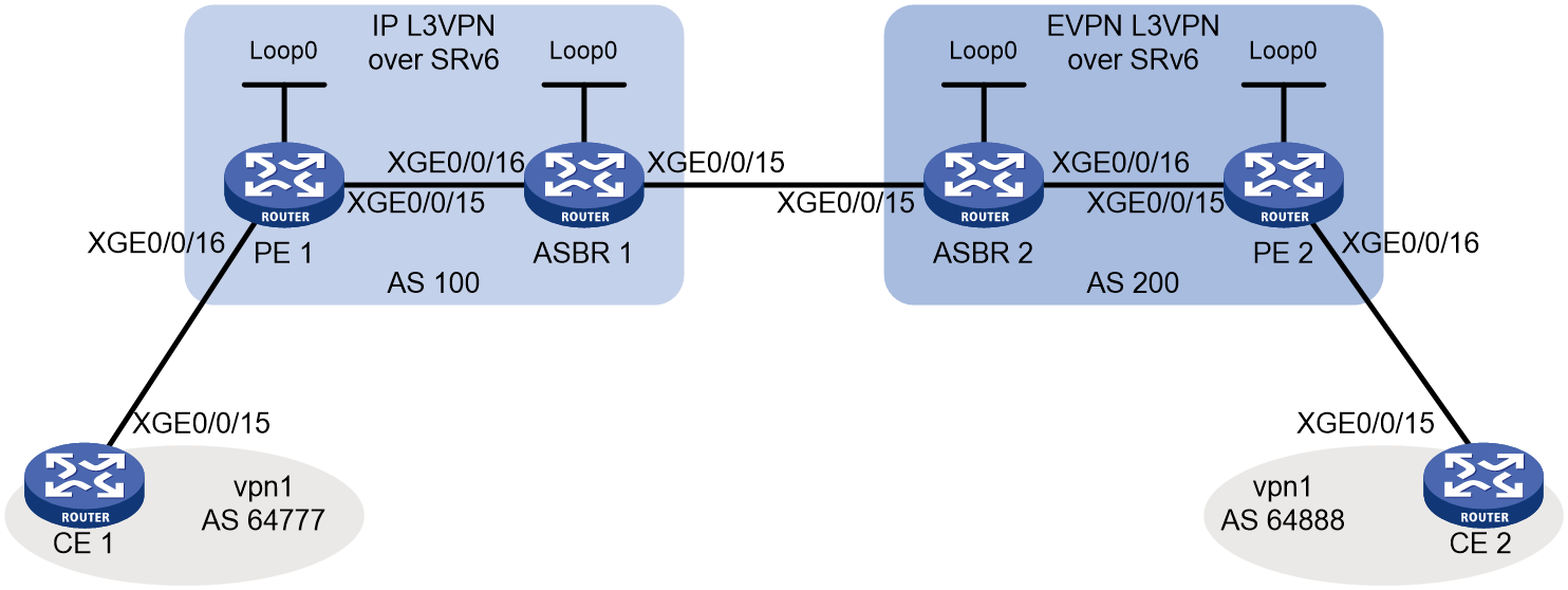
|
Device |
Interfaces |
IP address |
Device |
Interfaces |
IP address |
|
CE 1 |
XGE0/0/15 |
10.10.10.2/24 |
CE 2 |
XGE0/0/15 |
20.20.20.2/24 |
|
PE 1 |
Loop0 |
1::1/128 |
PE 2 |
Loop0 |
4::4/128 |
|
|
XGE0/0/15 |
2012::1/96 |
|
XGE0/0/15 |
2034::4/96 |
|
|
XGE0/0/16 |
10.10.10.1/24 |
|
XGE0/0/16 |
20.20.20.1/24 |
|
ASBR 1 |
Loop0 |
2::2/128 |
ASBR 2 |
Loop0 |
3::3/128 |
|
|
XGE0/0/15 |
2023::2/96 |
|
XGE0/0/15 |
2023::3/96 |
|
|
XGE0/0/16 |
2012::2/96 |
|
XGE0/0/16 |
2034::3/96 |
Procedure
1. Configure the IP address of each device interface. (Details not shown.)
2. Enable the CE and PE to exchange VPN routes
# Configure a VPN instance on PE 1 and connect CE 1 to PE 1.
<PE1> system-view
[PE1] ip vpn-instance vpn1
[PE1-vpn-instance-vpn1] route-distinguisher 1:1
[PE1-vpn-instance-vpn1] vpn-target 1:1
[PE1-vpn-instance-vpn1] quit
[PE1] interface ten-gigabitethernet 0/0/16
[PE1-Ten-GigabitEthernet0/0/16] ip binding vpn-instance vpn1
[PE1-Ten-GigabitEthernet0/0/16] ip address 10.10.10.1 24
[PE1-Ten-GigabitEthernet0/0/16] quit
# Configure a VPN instance on PE 2 and connect CE 2 to PE 2.
<PE2> system-view
[PE2] ip vpn-instance vpn1
[PE2-vpn-instance-vpn1] route-distinguisher 4:4
[PE2-vpn-instance-vpn1] vpn-target 1:1
[PE2-vpn-instance-vpn1] quit
[PE2] interface ten-gigabitethernet 0/0/16
[PE2-Ten-GigabitEthernet0/0/16] ip binding vpn-instance vpn1
[PE2-Ten-GigabitEthernet0/0/16] ip address 20.20.20.1 24
[PE2-Ten-GigabitEthernet0/0/16] quit
# Create EBGP peers between PE 1 and CE 1, and redistribute VPN routes to CE 1.
<CE1> system-view
[CE1] bgp 64777
[CE1-bgp-default] peer 10.10.10.1 as-number 100
[CE1-bgp-default] address-family ipv4 unicast
[CE1-bgp-default-ipv4] peer 10.10.10.1 enable
[CE1-bgp-default-ipv4] import-route direct
[CE1-bgp-default-ipv4] quit
[CE1-bgp-default] quit
# Create EBGP peers between PE 1 and CE 1, and redistribute VPN routes to PE 1.
[PE1] bgp 100
[PE1-bgp-default] router-id 1.1.1.1
[PE1-bgp-default] ip vpn-instance vpn1
[PE1-bgp-default-vpn1] peer 10.10.10.2 as-number 64777
[PE1-bgp-default-vpn1] address-family ipv4 unicast
[PE1-bgp-default-ipv4-vpn1] peer 10.10.10.2 enable
[PE1-bgp-default-ipv4-vpn1] quit
[PE1-bgp-default-vpn1] quit
# Create EBGP peers between PE 2 and CE 2, and redistribute VPN routes to CE 2.
<CE2> system-view
[CE2] bgp 64888
[CE2-bgp-default] peer 20.20.20.1 as-number 200
[CE2-bgp-default] address-family ipv4 unicast
[CE2-bgp-default-ipv4] peer 20.20.20.1 enable
[CE2-bgp-default-ipv4] import-route direct
[CE2-bgp-default-ipv4] quit
[CE2-bgp-default] quit
# Create EBGP peers between PE 2 and CE 2, and redistribute VPN routes to PE 2.
[PE2] bgp 200
[PE2-bgp-default] router-id 4.4.4.4
[PE2-bgp-default] ip vpn-instance vpn1
[PE2-bgp-default-vpn1] peer 20.20.20.2 as-number 64777
[PE2-bgp-default-vpn1] address-family ipv4 unicast
[PE2-bgp-default-ipv4-vpn1] peer 20.20.20.2 enable
[PE2-bgp-default-ipv4-vpn1] quit
[PE2-bgp-default-vpn1] quit
3. Configure IS-IS to establish IBGP sessions based on loopback interfaces and transmit locator routes.
# Configure PE 1.
[PE1] isis 1
[PE1-isis-1] is-level level-1
[PE1-isis-1] cost-style wide
[PE1-isis-1] network-entity 10.1111.1111.1111.00
[PE1-isis-1] address-family ipv6 unicast
[PE1-isis-1-ipv6] quit
[PE1-isis-1] quit
[PE1] interface loopback 0
[PE1-LoopBack0] isis ipv6 enable 1
[PE1-LoopBack0] quit
[PE1] interface ten-gigabitethernet 0/0/15
[PE1-Ten-GigabitEthernet0/0/15] isis ipv6 enable
[PE1-Ten-GigabitEthernet0/0/15] quit
# Configure ASBR 1.
<ASBR1> system-view
[ASBR1] isis 1
[ASBR1-isis-1] is-level level-1
[ASBR1-isis-1] cost-style wide
[ASBR1-isis-1] network-entity 10.2222.2222.2222.00
[ASBR1-isis-1] address-family ipv6 unicast
[ASBR1-isis-1-ipv6] quit
[ASBR1-isis-1] quit
[ASBR1] interface loopback 0
[ASBR1-LoopBack0] isis ipv6 enable 1
[ASBR1-LoopBack0] quit
[ASBR1] interface ten-gigabitethernet 0/0/16
[ASBR1-Ten-GigabitEthernet0/0/16] isis ipv6 enable 1
[ASBR1-Ten-GigabitEthernet0/0/16] quit
[ASBR1] isis 2
[ASBR1-isis-2] is-level level-1
[ASBR1-isis-2] cost-style wide
[ASBR1-isis-2] network-entity 20.2222.2222.2222.00
[ASBR1-isis-2] address-family ipv6 unicast
[ASBR1-isis-2-ipv6] quit
[ASBR1-isis-2] quit
[ASBR1] interface ten-gigabitethernet 0/0/15
[ASBR1-Ten-GigabitEthernet0/0/15] isis ipv6 enable 2
[ASBR1-Ten-GigabitEthernet0/0/15] quit
# Configure ASBR 2.
<ASBR2> system-view
[ASBR2] isis 1
[ASBR2-isis-1] is-level level-1
[ASBR2-isis-1] cost-style wide
[ASBR2-isis-1] network-entity 10.3333.3333.3333.00
[ASBR2-isis-1] address-family ipv6 unicast
[ASBR2-isis-1-ipv6] quit
[ASBR2-isis-1] quit
[ASBR2] interface loopback 0
[ASBR2-LoopBack0] isis ipv6 enable 1
[ASBR2-LoopBack0] quit
[ASBR2] interface ten-gigabitethernet 0/0/16
[ASBR2-Ten-GigabitEthernet0/0/16] isis ipv6 enable 1
[ASBR2-Ten-GigabitEthernet0/0/16] quit
[ASBR2] isis 2
[ASBR2-isis-2] is-level level-1
[ASBR2-isis-2] cost-style wide
[ASBR2-isis-2] network-entity 20.3333.3333.3333.00
[ASBR2-isis-2] address-family ipv6 unicast
[ASBR2-isis-2-ipv6] quit
[ASBR2-isis-2] quit
[ASBR2] interface ten-gigabitethernet 0/0/15
[ASBR2-Ten-GigabitEthernet0/0/15] isis ipv6 enable 2
[ASBR2-Ten-GigabitEthernet0/0/15] quit
# Configure PE 2.
[PE2] isis 1
[PE2-isis-1] is-level level-1
[PE2-isis-1] cost-style wide
[PE2-isis-1] network-entity 10.1111.1111.1111.00
[PE2-isis-1] address-family ipv6 unicast
[PE2-isis-1-ipv6] quit
[PE2-isis-1] quit
[PE2] interface loopback 0
[PE2-LoopBack0] isis ipv6 enable 1
[PE2-LoopBack0] quit
[PE2] interface ten-gigabitethernet 0/0/15
[PE2-Ten-GigabitEthernet0/0/15] isis ipv6 enable
[PE2-Ten-GigabitEthernet0/0/15] quit
4. Establish BGP VPNv4 and BGP EVPN sessions in the backbone network.
# Configure PE 1.
[PE1] bgp 100
[PE1-bgp-default] peer 2::2 as-number 100
[PE1-bgp-default] peer 2::2 connect-interface loopback 0
[PE1-bgp-default] address-family vpnv4
[PE1-bgp-default-vpnv4] peer 2::2 enable
[PE1-bgp-default-vpnv4] quit
[PE1-bgp-default] quit
# Configure ASBR 1.
[ASBR1] bgp 100
[ASBR1-bgp-default] router-id 2.2.2.2
[ASBR1-bgp-default] peer 1::1 as-number 100
[ASBR1-bgp-default] peer 1::1 connect-interface loopback 0
[ASBR1-bgp-default] peer 2023::3 as 200
[ASBR1-bgp-default] address-family vpnv4
[ASBR1-bgp-default-vpnv4] peer 1::1 enable
[ASBR1-bgp-default-vpnv4] peer 2023::3 enable
[ASBR1-bgp-default-vpnv4] quit
[ASBR1-bgp-default] quit
# Configure ASBR 2.
[ASBR2] bgp 200
[ASBR2-bgp-default] router-id 3.3.3.3
[ASBR2-bgp-default] peer 4::4 as-number 200
[ASBR2-bgp-default] peer 4::4 connect-interface loopback 0
[ASBR2-bgp-default] peer 2023::2 as 100
[ASBR2-bgp-default] address-family vpnv4
[ASBR2-bgp-default-vpnv4] peer 2023::2 enable
[ASBR2-bgp-default-vpnv4] quit
[ASBR2-bgp-default] address-family l2vpn evpn
[ASBR2-bgp-default-evpn] peer 4::4 enable
[ASBR2-bgp-default-evpn] quit
[ASBR2-bgp-default] quit
# Configure PE 2.
[PE2] bgp 200
[PE2-bgp-default] peer 3::3 as-number 200
[PE2-bgp-default] peer 3::3 connect-interface loopback 0
[PE2-bgp-default] address-family l2vpn evpn
[PE2-bgp-default-evpn] peer 3::3 enable
[PE2-bgp-default-evpn] quit
[PE2-bgp-default] quit
5. Configure SRv6
# Configure PE 1.
[PE1] segment-routing ipv6
[PE1-segment-routing-ipv6] encapsulation source-address 1::1
[PE1-segment-routing-ipv6] locator aaa ipv6-prefix 1:1:1:: 112 static 8
[PE1-segment-routing-ipv6-locator-aaa] quit
[PE1-segment-routing-ipv6] quit
[PE1] isis 1
[PE1-isis-1] address-family ipv6 unicast
[PE1-isis-1-ipv6] segment-routing ipv6 locator aaa
[PE1-isis-1-ipv6] quit
[PE1-isis-1] quit
# Configure ASBR 1.
[ASBR1] segment-routing ipv6
[ASBR1-segment-routing-ipv6] encapsulation source-address 2::2
[ASBR1-segment-routing-ipv6] locator aaa ipv6-prefix 2:2:2:: 112 static 8
[ASBR1-segment-routing-ipv6-locator-aaa] quit
[ASBR1-segment-routing-ipv6] quit
[ASBR1] isis 1
[ASBR1-isis-1] address-family ipv6 unicast
[ASBR1-isis-1-ipv6] segment-routing ipv6 locator aaa
[ASBR1-isis-1-ipv6] quit
[ASBR1-isis-1] quit
[ASBR1] isis 2
[ASBR1-isis-2] address-family ipv6 unicast
[ASBR1-isis-2-ipv6] segment-routing ipv6 locator aaa
[ASBR1-isis-2-ipv6] quit
[ASBR1-isis-2] quit
# Configure ASBR 2.
[ASBR2] segment-routing ipv6
[ASBR2-segment-routing-ipv6] encapsulation source-address 3::3
[ASBR2-segment-routing-ipv6] locator aaa ipv6-prefix 3:3:3:: 112 static 8
[ASBR2-segment-routing-ipv6-locator-aaa] quit
[ASBR2-segment-routing-ipv6] quit
[ASBR2] isis 1
[ASBR2-isis-1] address-family ipv6 unicast
[ASBR2-isis-1-ipv6] segment-routing ipv6 locator aaa
[ASBR2-isis-1-ipv6] quit
[ASBR2-isis-1] quit
[ASBR2] isis 2
[ASBR2-isis-2] address-family ipv6 unicast
[ASBR2-isis-2-ipv6] segment-routing ipv6 locator aaa
[ASBR2-isis-2-ipv6] quit
[ASBR2-isis-2] quit
# Configure PE 2.
[PE2] segment-routing ipv6
[PE2-segment-routing-ipv6] encapsulation source-address 4::4
[PE2-segment-routing-ipv6] locator aaa ipv6-prefix 4:4:4:: 112 static 8
[PE2-segment-routing-ipv6-locator-aaa] quit
[PE2-segment-routing-ipv6] quit
[PE2] isis 1
[PE2-isis-1] address-family ipv6 unicast
[PE2-isis-1-ipv6] segment-routing ipv6 locator aaa
[PE2-isis-1-ipv6] quit
[PE2-isis-1] quit
6. Enable the PEs and ASBRs to exchange BGP routes carrying SRv6 SIDs
# Configure PE 1.
[PE1] bgp 100
[PE1-bgp-default] ip vpn-instance vpn1
[PE1-bgp-default-vpn1] address-family ipv4 unicast
[PE1-bgp-default-ipv4-vpn1] segment-routing ipv6 locator aaa
[PE1-bgp-default-ipv4-vpn1] segment-routing ipv6 best-effort
[PE1-bgp-default-ipv4-vpn1] quit
[PE1-bgp-default-vpn1] quit
[PE1-bgp-default] address-family vpnv4
[PE1-bgp-default-vpnv4] peer 2::2 prefix-sid
[PE1-bgp-default-vpnv4] quit
[PE1-bgp-default] quit
# Configure ASBR 1.
[ASBR1] bgp 100
[ASBR1-bgp-default] address-family vpnv4
[ASBR1-bgp-default-vpnv4] undo policy vpn-target
[ASBR1-bgp-default-vpnv4] segment-routing ipv6 locator aaa
[ASBR1-bgp-default-vpnv4] segment-routing ipv6 best-effort
[ASBR1-bgp-default-vpnv4] peer 1::1 prefix-sid
[ASBR1-bgp-default-vpnv4] peer 2023::3 prefix-sid
[ASBR1-bgp-default-vpnv4] quit
[ASBR1-bgp-default] quit
# Configure ASBR 2.
[ASBR2] bgp 200
[ASBR2-bgp-default] address-family vpnv4
[ASBR2-bgp-default-vpnv4] undo policy vpn-target
[ASBR2-bgp-default-vpnv4] segment-routing ipv6 locator aaa
[ASBR2-bgp-default-vpnv4] segment-routing ipv6 best-effort
[ASBR2-bgp-default-vpnv4] peer 2023::2 prefix-sid
[ASBR2-bgp-default-vpnv4] peer 2023::2 re-originated stitch-evpn
[ASBR2-bgp-default-vpnv4] quit
[ASBR2-bgp-default] address-family l2vpn evpn
[ASBR2-bgp-default-evpn] undo policy vpn-target
[ASBR2-bgp-default-evpn] segment-routing ipv6 locator aaa evpn
[ASBR2-bgp-default-evpn] segment-routing ipv6 best-effort evpn
[ASBR2-bgp-default-evpn] peer 4::4 advertise encap-type srv6
[ASBR2-bgp-default-evpn] peer 4::4 re-originated ip-prefix stitch-l3vpn
[ASBR2-bgp-default-evpn] quit
[ASBR2-bgp-default] quit
# Configure PE 2.
[PE2] bgp 200
[PE2-bgp-default] ip vpn-instance vpn1
[PE2-bgp-default-vpn1] address-family ipv4 unicast
[PE2-bgp-default-ipv4-vpn1] segment-routing ipv6 locator aaa evpn
[PE2-bgp-default-ipv4-vpn1] segment-routing ipv6 best-effort evpn
[PE2-bgp-default-ipv4-vpn1] quit
[PE2-bgp-default-vpn1] quit
[PE2-bgp-default] address-family l2vpn evpn
[PE2-bgp-default-evpn] peer 3::3 advertise encap-type srv6
[PE2-bgp-default-evpn] quit
[PE2-bgp-default] quit
7. Enable SRv6 network cross-AS intercommunication on the ASBR
# Configure ASBR 1.
[ASBR1] bgp 100
[ASBR1-bgp-default] address-family vpnv4
[ASBR1-bgp-default-vpnv4] srv6-inter-as enable
[ASBR1-bgp-default-vpnv4] quit
[ASBR1-bgp-default] address-family l2vpn evpn
[ASBR1-bgp-default-evpn] srv6-inter-as enable
[ASBR1-bgp-default-evpn] quit
[ASBR1-bgp-default] quit
# Configure ASBR 2.
[ASBR2] bgp 200
[ASBR2-bgp-default] address-family vpnv4
[ASBR2-bgp-default-vpnv4] srv6-inter-as enable
[ASBR2-bgp-default-vpnv4] quit
[ASBR2-bgp-default] address-family l2vpn evpn
[ASBR2-bgp-default-evpn] srv6-inter-as enable
[ASBR2-bgp-default-evpn] quit
[ASBR2-bgp-default] quit
Verifying the configuration
# Display BGP routing information on PE 2.
[PE2] display bgp l2vpn evpn
BGP local router ID is 4.4.4.4
Status codes: * - valid, > - best, d - dampened, h - history,
s - suppressed, S - stale, i - internal, e - external
a - additional-path
Origin: i - IGP, e - EGP, ? - incomplete
Total number of routes from all PEs: 1
Route distinguisher: 1:1
Total number of routes: 1
* >i Network : [5][0][24][10.10.10.0]/80
NextHop : 3::3 LocPrf : 100
PrefVal : 0 OutLabel : 0
MED :
Path/Ogn: 100i
Route distinguisher: 4:4(vpn1)
Total number of routes: 1
* > Network : [5][0][24][20.20.20.0]/80
NextHop : 127.0.0.1 LocPrf :
PrefVal : 32768 OutLabel : NULL
MED : 0
Path/Ogn: i
[PE2] display bgp routing-table ipv4 vpn-instance vpn1
Total number of routes: 2
BGP local router ID is 4.4.4.4
Status codes: * - valid, > - best, d - dampened, h - history,
s - suppressed, S - stale, i - internal, e - external
a - additional-path
Origin: i - IGP, e - EGP, ? - incomplete
Network NextHop MED LocPrf PrefVal Path/Ogn
* >i 10.10.10.10/32 3::3 100 0 100i
* > 20.20.20.20/32 127.0.0.1 0 32768 i
The output shows that PE 2 has successfully received route 10.10.10.0/24 converted into a BGP EVPN route, and the route is added to the BGP-VPN instance and selected as the optimal route.
# Display detailed information about route [5][0][32][10.10.10.10]/80 on PE 2.
[PE2] display bgp l2vpn evpn [5][0][32][10.10.10.10]/80
BGP local router ID: 4.4.4.4
Local AS number: 200
Route distinguisher: 1:1
Total number of routes: 1
Paths: 1 available, 1 best
BGP routing table information of [5][0][32][10.10.10.10]/80:
From : 3::3 (3.3.3.3)
Rely nexthop : FE80::6AA0:AAFF:FE8E:307
Original nexthop: 3::3
Out interface : Ten-GigabitEthernet0/0/15
Route age : 04h43m34s
OutLabel : 0
Ext-Community : <RT: 1:1>
RxPathID : 0x0
TxPathID : 0x0
PrefixSID : End.R SID <3:3:3::10C>
SRv6 Service TLV (37 bytes):
Type: SRV6 L3 Service TLV (5)
Length: 34 bytes, Reserved: 0x0
SRv6 Service Information Sub-TLV (33 bytes):
Type: 1 Length: 30, Rsvdl: 0x0
SID Flags: 0x0 Endpoint behavior: 0x8018 Rsvd2: 0x0
SRv6 SID Sub-Sub-TLV:
Type: 1 Len: 6
BL: 112 NL: 0 FL: 16 AL: 0 TL: 0 TO: 0
AS-path : 100
Origin : igp
Attribute value : localpref 100, pref-val 0
State : valid, internal, best
Source type : local
IP precedence : N/A
QoS local ID : N/A
Traffic index : N/A
EVPN route type : IP prefix advertisement route
ESI : 0000.0000.0000.0000.0000
Ethernet tag ID : 0
IP prefix : 10.10.10.10/32
Gateway address : 0.0.0.0
MPLS label : 0
Tunnel policy : NULL
Rely tunnel IDs : N/A
Re-origination : Disable
The output shows that route 10.10.10.0/24 received by PE 2 carries the End.R SID converted by ASBR 2.
# Verify that the obtained information about route 20.20.20.0/24 on PE 1 is similar to that on PE 2.
# Verify that you can ping subnet 20.20.20.0/24 attached to CE 2 on CE 1.
[CE1] ping -vpn-instance vpn1 20.20.20.2
Ping 20.20.20.2 (20.20.20.2): 56 data bytes, press CTRL+C to break
56 bytes from 20.20.20.2: icmp_seq=0 ttl=255 time=2.212 ms
56 bytes from 20.20.20.2: icmp_seq=1 ttl=255 time=5.431 ms
56 bytes from 20.20.20.2: icmp_seq=2 ttl=255 time=2.024 ms
56 bytes from 20.20.20.2: icmp_seq=3 ttl=255 time=1.180 ms
56 bytes from 20.20.20.2: icmp_seq=4 ttl=255 time=81.836 ms
--- Ping statistics for 20.20.20.2 in VPN instance vpn1 ---
5 packet(s) transmitted, 5 packet(s) received, 0.0% packet loss
round-trip min/avg/max/std-dev = 1.180/18.537/81.836/31.683 ms
