- Table of Contents
-
- 10-Segment Routing Configuration Guide
- 00-Preface
- 01-SR-MPLS configuration
- 02-SR-MPLS TE policy configuration
- 03-SRv6 configuration
- 04-SRv6 TE policy configuration
- 05-SRv6 VPN overview
- 06-IP L3VPN over SRv6 configuration
- 07-EVPN L3VPN over SRv6 configuration
- 08-EVPN VPWS over SRv6 configuration
- 09-EVPN VPLS over SRv6 configuration
- 10-Public network IP over SRv6 configuration
- 11-SRv6 OAM configuration
- 12-SRv6 network slicing configuration
- 13-SRv6 service chain configuration
- Related Documents
-
| Title | Size | Download |
|---|---|---|
| 03-SRv6 configuration | 1.04 MB |
Directing traffic to an SRv6 tunnel
G-SID format in 32-bit G-SRv6 compression
G-SRv6 packet in 32-bit G-SRv6 compression
16-bit G-SRv6 compression classification
16-bit compression with a combination of NEXT and COC flavors
16-bit compression scheme where only the NEXT flavor is supported
16-bit compression scheme where only the COC flavor is supported
BGP-LS advertisement of link attribute information
Topology-Independent Loop-Free Alternate Fast Re-Route (TI-LFA FRR)
Microloop avoidance after a network failure
SR microloop avoidance after a failure recovery
Restrictions and guidelines: SRv6 configuration
Configuring non-compressible SRv6 SIDs
Configuring the local locator and opcode
Configuring the remote locator
Configuring SRv6 SIDs on a COC32 locator
Configuring SRv6 SIDs on a COC-both locator
Configuring SRv6 SIDs on a COC16 locator
Configuring the length of the GIB
Configuring dynamic End.X SID deletion delay
Configuring the delay time to flush static End.X SIDs to the FIB
Using IGP to advertise SRv6 SIDs
Enabling BGP to advertise routes for a locator
Configuring a BGP-EPE SRv6 peer set
Configuring delay advertisement for BGP-EPE
Configuring packet loss rate advertisement for BGP-EPE
Configuring bandwidth advertisement for BGP-EPE
Configuring dynamic SID deletion delay
Configuring the BGP virtual link feature
Restrictions and guidelines for TI-LFA FRR
Specifying a repair list encapsulation mode for TI-LFA FRR
Disabling an interface from participating in TI-LFA calculation
Enabling FRR microloop avoidance
Enabling SR microloop avoidance
Specifying an SID list encapsulation mode for SR microloop avoidance
Configuring SR microloop avoidance to encapsulate only strict SIDs in the SID list
Configuring the SRv6 DiffServ mode
Enabling SNMP notifications for SRv6
Display and maintenance commands for SRv6
Example: Configuring IPv6 IS-IS TI-LFA FRR
Example: Configuring SRv6 BGP-EPE
SRv6 basics
About SRv6
Segment Routing (SR) is a source routing technology. The source node selects a path for packet forwarding, and then encodes the path in the packet header as an ordered list of segments. Each segment is identified by a segment identifier (SID). The SR nodes along the path forward the packets based on the SIDs in the packets. None of the nodes except the source node needs to maintain the path state.
IPv6 SR (SRv6) uses IPv6 addresses as SIDs to forward packets.
Basic concepts
SR node roles
The nodes on an SRv6 network can have one or multiple of the following roles:
· Source node—Responsible for inserting an SRH into the IPv6 header of IPv6 packets, or encapsulating IPv6 packets with an outer IPv6 header and inserting an SRH into the outer IPv6 header. A source node steers traffic to the SRv6 path defined in the segment list in the SRH.
¡ If the segment list contains only one SID and the SRH is not required to include information or TLV, the source node only sets the SID as the destination address in the IPv6 header, without inserting an SRH.
¡ If the segment list contains multiple SIDs, the source node must insert an SRH to the packets.
A source node can be the originator of SRv6 packets or the edge device of an SRv6 domain.
· Transit node—Forwards IPv6 packets along the SRv6 path. A transit node does not participate in SRv6 processing. It can be an SRv6-aware or SRv6-unaware node.
· Endpoint node—Performs an SRv6 function for received SRv6 packets. The IPv6 destination address of the received SRv6 packets must be an SRv6 SID configured on the endpoint node. The endpoint node processes the packets based on the SRv6 SID and updates the SRH.
A node can be the source node in one SRv6 path and a transit node or endpoint node in another SRv6 path.
SID portions
In SRv6, a SID represents a segment that represents a network function or instruction to execute on a packet.
An SRv6 SID is in the format of an IPv6 address, but the IPv6 address does not belong to any interface on any device.
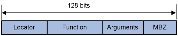
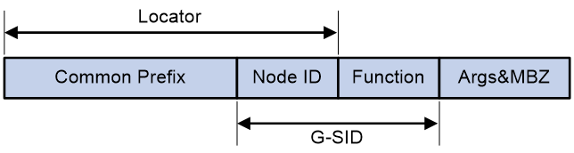
As shown in Figure 1, an SRv6 SID contains the Locator, Function, Arguments, and Must be zero (MBZ) portions.
· Locator—Identifies the network segment of the SID. An SRv6 node advertises IPv6 segments identified by locators to the network through routing protocols such as IGP, to help other devices forward packets to that SRv6 node. Therefore, locators are typically used for SRv6 routing and addressing. The locator of an SRv6 SID must be unique in the SR domain.
· Function—Contains an opcode that identifies the network function (local instruction) bound to a SID. When an SRv6 node receives an SRv6 packet and detects that the IPv6 destination address matches an SRv6 SID in the local SID table, the node analyzes the Function field. Then, it locates and executes the local operation instruction for the function. For example, an SRv6 node is configured with the opcode 101 end-x interface A command for a SID. This command indicates that an opcode value of 101 in the Function field associates with the End.X behavior. If the destination address of an incoming SRv6 packet matches this local SRv6 SID, the node forwards the packet from interface A (the interface identified by End.X) as instructed.
· Arguments—Defines flow and service parameters for SRv6 packets, an optional field in SRv6 SIDs.
· MBZ—When the total number of bits in the Locator, Function, and Arguments portions is less than 128 bits, the lowest bits are padded with 0s.
All SRv6 SIDs are allocated from the locator configured by using the locator command. SRv6 SIDs are divided into different categories depending on the locator type and length. Typically, 128-bit SRv6 SIDs are encapsulated into SRv6 packets. This type of SRv6 SIDs are allocated from common locators.
Figure 2 Common locator
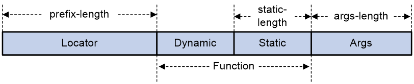
Common locators can allocate common SRv6 SIDs, and common SRv6 SIDs include static and dynamic SRv6 SIDs. The formats are as follows:
· A static SRv6 SID is generated based on the following formula: static SRv6 SID = ipv6-prefix + 0 + opcode + 0.
¡ The ipv6-prefix argument represents the IPv6 prefix specified by using the ipv6-address and prefix-length arguments in the locator command. The number of bits occupied by the IPv6 prefix is configured by using the prefix-length argument.
¡ The number of bits occupied by 0s (following the ipv6-prefix portion) is 128 - prefix-length - static-length - args-length.
¡ The opcode argument represents the static portion in the Function field. The number of bits occupied by the opcode is the value of the static-length argument. The number of bits occupied by 0s (following the opcode portion) is the value of the args-length argument.
· A dynamic SRv6 SID is generated based on the following formula: dynamic SRv6 SID = ipv6-prefix + dynamic + static + 0.
¡ The ipv6-prefix argument represents the IPv6 prefix specified by using the ipv6-address and prefix-length arguments in the locator command. The number of bits occupied by the IPv6 prefix is configured by using the prefix-length argument.
¡ The dynamic argument represents the dynamic portion in the Function field. The value for this portion cannot be all zeros. The number of bits occupied by this portion is 128 - prefix-length - static-length - args-length.
¡ The static argument represents the static portion in the Function field. The number of bits occupied by this portion is static-length. This portion can use any value. The number of bits occupied by 0s is the value of the args-length argument.
Assume that you configure the locator test1 ipv6-prefix 100:200:DB8:ABCD:: 64 static 24 args 32 command.
¡ The locator is 100:200:DB8:ABCD::. The length is 64 bits.
¡ The static portion length is 24 bits.
¡ The Args portion length is 32 bits.
¡ The dynamic portion length is 8 bits.
In this example, the following non-compressible static SRv6 SID range and dynamic SRv6 SID range are obtained on the locator:
¡ The start value for static SRv6 SIDs is 100:200:DB8:ABCD:0:1::.
¡ The end value for static SRv6 SIDs is 100:200:DB8:ABCD:FF:FFFF::.
¡ The start value for dynamic SRv6 SIDs is 100:200:DB8:ABCD:100::.
¡ The end value for dynamic SRv6 SIDs is 100:200:DB8:ABCD:FFFF:FFFF::.
SRv6 endpoint behaviors
The local instruction identified by the Function field of an SRv6 SID is a node behavior that guides packet forwarding and processing. This local instruction is called SRv6 endpoint behavior. RFC 8986 defines opcode values for most types of node behaviors. From a network configuration perspective, different node forwarding behaviors are SRv6 SIDs with various functional types. The types of SRv6 SID include, but are not limited to the following:
· End SID—Identifies a node in the network, representing the prefix of a destination address. Upon arrival of packets at the node, if the SL is greater than 0, the node behavior is to decrease the SL by 1, extract the next SID from the SRH to update the destination address field in the IPv6 header, search for the routing table, and then forward the packet. There are two special types of End SIDs, End(COC32) and End(COCNONE). For more information about these types of SIDs, see the G-SRv6 section.
· End.X SID—Identifies a link in the network. Upon arrival of packets at the node that generated the SID, if the SL is greater than 0, the node behavior is to decrease the SL by 1, extract the next SID from the SRH to update the IPv6 header's destination address field, and then forward the packet from the link identified by the End.X SID. There are two special types of End.X SIDs, End.X(COC32) and End.X(COCNONE). For more information about these types of SIDs, see the G-SRv6 section.
· End.DT4 SID—Similar to a private network label in an MPLS L3VPN network, it identifies an IPv4 VPN instance in the network. The function of an End.DT4 SID is decapsulating packets and searching the routing table of the corresponding IPv4 VPN instance to forward the packets. End.DT4 SIDs are applicable to IPv4 private network access scenarios.
· End.DT6 SID—Similar to a private network label in an MPLS L3VPN network, it identifies an IPv6 VPN instance in the network. The function of an End.DT6 SID is decapsulating packets and searching the routing table of the corresponding IPv6 VPN instance to forward the packets. End.DT6 SIDs are applicable to IPv6 private network access scenarios.
· End.DT46 SID—Similar to a private network label in an MPLS L3VPN network, it identifies an IPv4 or IPv6 VPN instance in the network. End.DT46 SIDs are applicable to IPv4 and IPv6 private network concurrent access scenarios.
· End.DX4 SID—Identifies an IPv4 next hop from a PE to a CE in an IPv4 VPN instance in the network. The function of an End.DX4 SID is decapsulating packets and forwarding the decapsulated IPv4 packets out of the Layer 3 interface bound to the SID to a specific next hop. End.DX4 SIDs are applicable to IPv4 private network access scenarios.
· End.DX6 SID—Identifies an IPv6 next hop from a PE to a CE in an IPv6 VPN instance in the network. The function of an End.DX6 SID is decapsulating packets and forwarding the decapsulated IPv6 packets out of the Layer 3 interface bound to the SID to a specific next hop. End.DX6 SIDs are applicable to IPv6 private network access scenarios.
· End.DX2 SID—Identifies one end of a Layer 2 cross-connect in the EVPN VPWS over SRv6 scenario. The function of an End.DX2 SID is decapsulating packets and forwarding the decapsulated packets to the output interface of the SID.
· End.DX2L SID—Identifies packets that come from a bypass SRv6 PW. The packets will not be forwarded back to the bypass SRv6 PW for loop prevention. The function of an End.DX2L SID is removing the outer IPv6 header and SRH of packets and forwarding the decapsulated packets to the output interface of the SID. End.DX2L SIDs are applicable to EVPN VPWS over SRv6 multihomed sites.
· End.DT2M SID—Identifies one end of a Layer 2 cross-connect for EVPN VPLS over SRv6 BUM traffic and floods traffic. The function of an End.DT2M SID is decapsulating packets and flooding the decapsulated packets in the VSI.
· End.DT2U SID—Identifies one end of a Layer 2 cross-connect and performs unicast forwarding. The function of an End.DT2U SID is removing the outer IPv6 header and SRH of packets, looking up the MAC address table for the destination MAC address, and forwarding the packets to the output interface based on the MAC address entry. End.DT2U SIDs are applicable to EVPN VPLS unicast traffic.
· End.DT2UL SID—Identifies packets that come from a bypass SRv6 PW. The packets will not be forwarded back to the bypass SRv6 PW for loop prevention. The function of an End.DT2UL SID is removing the outer IPv6 header and SRH of packets and forwarding the packets to the output interface through destination MAC address lookup. End.DT2UL SIDs are applicable to EVPN VPLS over SRv6 multihomed sites.
· End.OP SID—Applies to the SRv6 OAM scenario. For more information about End.OP SIDs, see "Configuring SRv6 OAM."
· End.M SID—Applies to the SRv6 TE policy tailend protection scenario. For more information about End.M SIDs, see "Configuring SRv6 TE policies."
· End.T SID—Applies to the inter-AS option B solution. For more information about End.T SIDs, see "Configuring IP L3VPN over SRv6" and "Configuring EVPN L3VPN over SRv6."
· End.R SID—Applies to for SRv6 VPN Option B inter-domain communication scenarios. The forwarding action corresponding to the End.R SID is to remove the outer IPv6 header, look up the IPv6 FIB table based on the End.R SID, and re-encapsulate the packet with a new outer IPv6 header for forwarding based on the lookup results. For more information about End.R SIDs, see "Configuring IP L3VPN over SRv6."
· End.AS SID—Applies to the SRv6 service chain static proxy scenario. For more information about End.AS SIDs, see "Configuring SRv6 service chains."
· End.AM SID—Applies to the SRv6 service chain masquerading scenario. For more information about End.AM SIDs, see "Configuring SRv6 service chains."
· End.B6.Encaps—Applies to the scenario where an SRv6 ingress node steers traffic to an SRv6 TE policy or stitches an SRv6 TE policy by using a BSID. The node behavior is to encapsulate a new IPv6 header and SRH onto the received packet.
· End.B6.Encaps.Red—Applies to the scenario where an SRv6 ingress node steers traffic to an SRv6 TE policy or stitches an SRv6 TE policy by using a BSID. The node behavior is to encapsulate the SIDs except for the first SID in the SRv6 TE policy’s SID list when it encapsulates an IPv6 header and SRH onto the received packet to reduce the SRH length.
· End.B6.Insert—Applies to the scenario where an SRv6 ingress node steers traffic to an SRv6 TE policy or stitches an SRv6 TE policy by using a BSID. The node behavior is to encapsulate an SRH header onto the received packet.
· End.B6.Insert.Red—Applies to the scenario where an SRv6 ingress node steers traffic to an SRv6 TE policy or stitches an SRv6 TE policy by using a BSID. The node behavior is to insert an SRH into the received IPv6 packet and to encapsulate the SIDs except for the first SID in the SRv6 TE policy’s SID list to reduce the SRH length.
· End.XSID—Applies to the scenario where BFD detects the specified reverse path in an SRv6 TE policy. The node behavior is to encapsulate new IPv6 header and SRH header onto the BFD echo packet header and encapsulate the local End.XSID onto SRH[0] in the SRH header SID list. For more information about SRv6 TE policy reverse path detection by BFD, see "Configuring SRv6 TE policy."
· Src.DT4 SID—Identifies the source address for a BIERv6 tunnel in an IPv4 multicast VPN. In BIER multicast VPN scenarios, the forwarding action is to decapsulate the packet and look up IPv4 table entries. For more information about BIERv6 tunnel source addresses, see "Configuring multicast VPN" in IP Multicast Configuration Guide.
· Src.DT6 SID—Identifies the source address for a BIERv6 tunnel in an IPv6 multicast VPN. In BIER multicast VPN scenarios, the forwarding action is to decapsulate the packet and look up IPv6 table entries. For more information about BIERv6 tunnel source addresses, see "Configuring multicast VPN" in IP Multicast Configuration Guide.
· End.BIER SID—Applies to BIERv6 scenarios. For more information about End.BIER SIDs, see "Configuring BIER" in BIER Configuration Guide.
· End.RGB SID—Used in MSR6 scenarios. For more information about End.RGB SIDs, see "Configuring BIER" in BIER Configuration Guide.
· End.DX2.AUTO—H3C-proprietary SIDs, which are used only for rapid service deployment scenarios such as PPPoE over IPv6 in access networks. In scenarios such as PPPoE dial-up access or dedicated access, a large number of customer-side CPE devices are widely deployed. To deploy services quickly and avoid on-site configuration, you can deploy a centralized controller to manage CPE devices through TR-069 and assign the SRv6 SID of the service gateway (SGW) to the CPE devices. This SID identifies the traffic from CPEs to the SGW. The SGW acts as the egress for CPE services. The following uses PPPoE authentication and traffic forwarding as an example to describe the communication between a customer CPE and the SGW:
a. After a CPE comes online, it uses PPPoE for authentication on the SGW. It encapsulates the PPPoE packets with an IPv6 header and an Ethernet frame header for PPPoE over IPv6 encapsulation. The destination IP address in the IPv6 header is the SGW's End.DX2.AUTO type SRv6 SID, and the source address is the CPE's service SID.
b. The SGW authenticates the CPE through an AAA server and allocates the address for the PPPoE WAN port to the CPE after the CPE passes authentication. The SGW records the mappings between the PPPoE session ID and the outer source IP address. It then creates an <IP address, PPPoE MAC> entry based on the End.DX2.AUTO type SRv6 SID in the outer IPv6 header of the PPPoE packet.
c. After authentication, the SGW obtains the related authorization information allocated by the AAA server, for example, rate limits.
d. When the CPE receives a service packet from the internal network, it encapsulates the original service packet with an IPv6 header and an Ethernet frame header. The IPv6 packet's destination IP address is the SGW's End.DX2.AUTO type SRv6 SID, and the source address is the CPE's service SID. After the SGW receives the service packet, it decapsulates the outer IPv6 header based on the action associated with the End.DX2.AUTO type SRv6 SID, and then forwards the remaining packet to the L2VE interface associated with the SID, terminating the L2VPN packet. Then, it looks up the routing table in the associated VRF to determine the packet's next destination, and then forwards the packet through the L3VE interface associated with that VRF.
Use IGP to advertise SRv6 SIDs for an SR node. The other SR nodes will generate route entries of that SR node based on the advertised information.
SRv6 SID flavors
SID flavors can be combined with some node behaviors to form new node behaviors. For example, node behavior End.X can be combined flavor PSP to form a new node behavior called End.X with PSP. Use SRv6 SID flavors to change the forwarding behaviors of SRv6 SIDs to meet multiple service requirements. The following SRv6 SID flavors are supported:
· NO-FLAVOR—The SRv6 SID does not carry any flavors.
· Penultimate Segment POP of the SRH (PSP)—The penultimate SRv6 node removes the SRH to reduce the workload of the end SRv6 node and improve the forwarding efficiency. The end SRv6 node does not read the SRH, and it only looks up the local SID table for the destination IPv6 address of packets to forward the packets.
· NO PSP—The penultimate SRv6 node does not remove the SRH. For correct connectivity detection in the SRv6 OAM scenario, make sure the SRH is not removed on the penultimate SRv6 node. The device needs to obtain the SID from the SRH to identify the link connectivity. (This flavor type is not supported in the current software version.)
· Ultimate Segment POP of the SRH (USP)—The ultimate SRv6 node (endpoint node) removes the SRH from the packets. In an SRv6 VPN network, upon obtaining the forwarding action based on the SID, the PE removes the SRH from the packets and forwards the packets to the CE.
· Ultimate Segment Decapsulation (USD)—The ultimate SRv6 node (endpoint node) removes the outer IPv6 header from the packets. In the TI-LFA scenario, the endpoint node in the repair list removes the outer IPv6 header from the packets and forwards the decapsulated packets to the destination node.
· Continue of Compression (COC)—A COC flavor identifies the next SID as a compressed G-SID, either 16-bit or 32-bit, in packet encapsulation. In packet forwarding, SIDs that carry the COC flavor support the replace action. When an SRv6 packet is forwarded to an endpoint node, if the local SID of that node has the COC flavor and the current SID is the last SID or G-SID in the IPv6 destination address, the node extracts a 16-bit or 32-bit G-SID from the 128-bit address space of the encapsulated SID. This G-SID is then replaced in the IPv6 packet's destination address, forming a new SID with a common prefix. This new SID guides G-SRv6 packet forwarding. For more information about the replace action, see "16-bit G-SRv6 compression."
· NEXT—A NEXT flavor identifies a 16-bit compressed G-SID in packet encapsulation. In packet forwarding, SIDs that carry the NEXT flavor support the move action. When an SRv6 packet is forwarded to an endpoint node, if the local SID of that node has the NEXT flavor and the current G-SID is not the last G-SID in the IPv6 destination address, the node moves the next G-SID to the position of the current G-SID to guide G-SRv6 packet forwarding. For more information about the move action, see "16-bit G-SRv6 compression."
The device supports advertising SRv6 SIDs with multiple flavor types through IGP or BGP. Therefore, a SID might carry different flavors, for example, End X with PSP&USD.
Local SID forwarding table
An SRv6-enabled node maintains a local SID forwarding table that records the SRv6 SIDs generated on the local node. The local SID forwarding table has the following functions:
· Stores local generated SRv6 SID forwarding information.
· Stores SRv6 SID operation types.
Segment List
A Segment List is an ordered list of SIDs, which is also referred to as a Segment Identifier (SID) list in this document. The SR nodes forward packets based on the SIDs in the order that they are arranged in the SID list.
SRv6 tunnel
An SRv6 tunnel is a virtual point-to-point connection established between the SRv6 ingress node and egress node. IPv6 packets are encapsulated at the ingress node and de-encapsulated at the egress node.
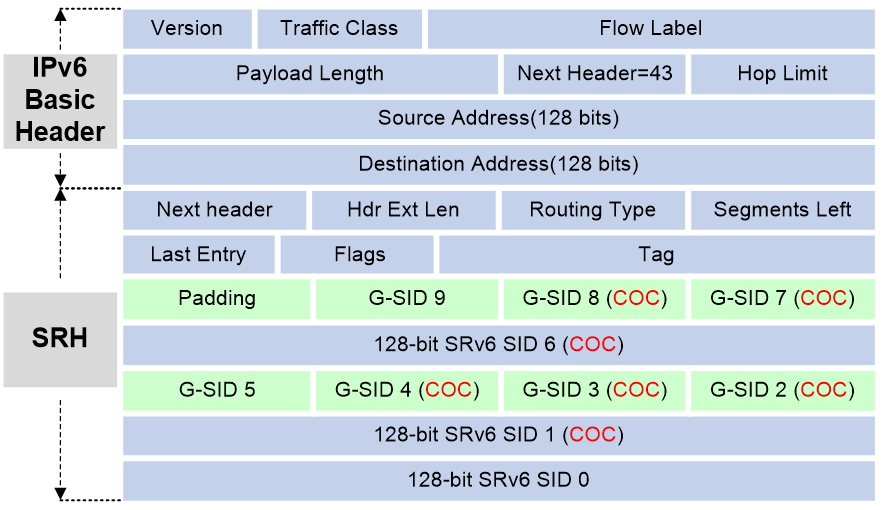
SRv6 packet format
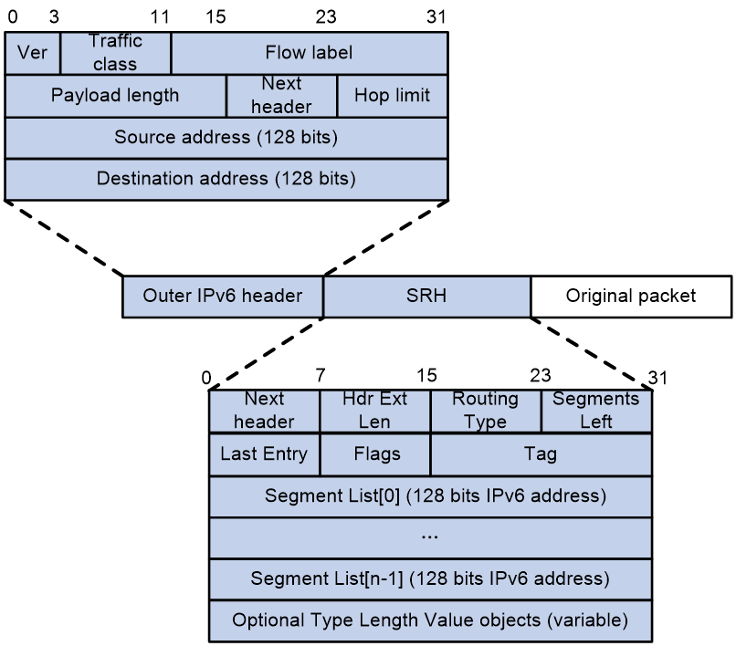
An outer IPv6 header and a Segment Routing Header (SRH) are added to the original Layer 3 data packet to form an SRv6 packet.
As shown in Figure 3, the value for the Next Header field is 43 in the outer IPv6 header, which indicates that the header next to the IPv6 header is a routing extension header. The value for the Routing Type field in the routing extension header is 4, which indicates that the routing extension header is an SRH. The SRH header contains the following fields:
· 8-bit Next Header—Identifies the type of the header next to the SRH.
· 8-bit Hdr Ext Len—Length of the SRH header in 8-octet units, not including the first 8 octets.
· 8-bit Routing Type—The value for this field is 4, which represents SRH.
· 8-bit Segments Left—Contains the index of the next segment to inspect in the Segment List. The Segments Left field is set to n-1 where n is the number of segments in the Segment List. Segments Left is decremented at each segment.
· 8-bit Last Entry—Contains the index of the first SID in the path used to forward the packet.
· 8-bit Flags—Contains flags.
· 16-bit Tag—Tags a packet as part of a class or group of packets, for example, packets sharing the same set of properties.
· Segment List—Contains 128-bit IPv6 addresses representing the ordered segments. The Segment List is encoded starting from the last segment of the path. The first element of the segment list (Segment List [0]) contains the last segment of the path, the second element (Segment List [1]) contains the penultimate segment of the path and so on. The number enclosed in a pair of brackets is the index of a segment.
SRv6 packet forwarding
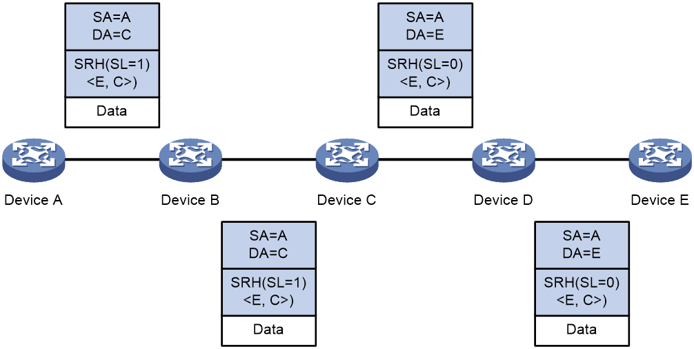
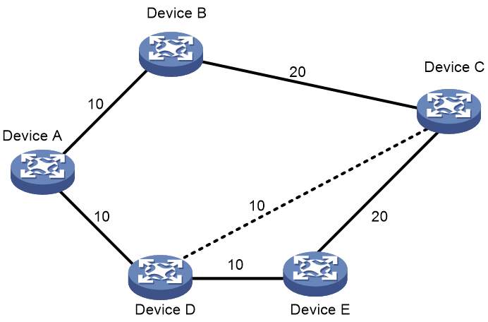
As shown in Figure 4, a source node receives a packet that matches an SRv6 path. Device A is the source node, Device C and Device E are endpoint nodes, and Device B and Device D are transit nodes. The packet is forwarded through the SRv6 path as follows:
1. Upon receiving an IPv6 packet, Device A performs the following operations:
a. Encapsulates an SRH to the packet. The packet must pass two segments to reach Device E, so the Segments Left (SL) in the SRH is set to 1 (the number of segments along the path minus 1). The Segment List contains Segment List [0]=E and Segment List [1]=C.
b. Encapsulates an outer IPv6 header to the packet. The source address of the IPv6 header is an IP address on Device A and the destination address is determined by the SL value. On Device A, the SL value is 1, which points to the SID on Device C, so the destination address is the SID on Device C.
c. Looks up the routing table based on the destination address of the outer IPv6 header and forwards the packet to Device B.
2. Device B looks up the routing table based on the destination address of the outer IPv6 header and forwards the packet to Device C.
3. Device C performs the following operations:
a. Checks the SL value in the SRH and decreases the value by 1 if the SL value is greater than 0.
b. Updates the destination address to the address pointed by the SL. In this example, the SL is 0, which points to the SID on Device E. Device C replaces the destination address in the outer IPv6 header with the SID on Device E.
c. Looks up the routing table based on the destination address of the outer IPv6 header and forwards the packet to Device D.
4. Device D looks up the routing table based on the destination address of the outer IPv6 header and forwards the packet to Device E.
5. Device E checks the SL value in the SRH and finds that the value has decreased to 0. The device performs the following operations:
a. Decapsulates the packet by removing the outer IPv6 header and the SRH.
b. Forwards the original packet to the destination based on the destination address.
Figure 4 SRv6 packet forwarding
Directing traffic to an SRv6 tunnel
After an SRv6 tunnel is established, traffic is not forwarded on the tunnel automatically. You must direct the traffic to the tunnel by configuring a static route or automatic route advertisement.
Static routing
You can direct traffic to an SRv6 tunnel by creating a static route that reaches the destination through the tunnel interface on the source node. This is the easiest way to implement SRv6 tunnel forwarding. When traffic to multiple networks is to be forwarded through the SRv6 tunnel, you must configure multiple static routes, resulting in increased configuration and maintenance workloads.
For more information about static routing, see Layer 3—IP Routing Configuration Guide.
Automatic route advertisement
Automatic route advertisement distributes the SRv6 tunnel to the IGP (OSPF or IS-IS), so the SRv6 tunnel can participate in IGP route calculation. Automatic route advertisement is easy to configure and maintain.
Automatic route advertisement can be implemented by using the following methods:
· IGP shortcut—Also known as AutoRoute Announce. It considers the SRv6 tunnel as a link that directly connects the tunnel ingress node and the egress node. Only the ingress node uses the SRv6 tunnel during IGP route calculation.
· Forwarding adjacency—Considers the SRv6 tunnel as a link that directly connects the tunnel ingress node and the egress node, and advertises the link to the network through an IGP. Every node in the network uses the SRv6 tunnel during IGP route calculation.
|
|
IMPORTANT: Only IGP shortcut is supported in the current software version. |
As shown in Figure 5, an SRv6 tunnel exists from Device D to Device C. IGP shortcut enables only the ingress node Device D to use the SRv6 tunnel in IGP route calculation. Device A cannot use this tunnel to reach Device C. With forwarding adjacency enabled, Device A can learn this SRv6 tunnel and transfer traffic to Device C by forwarding the traffic to Device D.
Figure 5 IGP shortcut and forwarding adjacency diagram
G-SRv6
Background
In an SRv6 TE policy scenario, the administrator needs to add the 128-bit SRv6 SIDs of SRv6 nodes on the packet forwarding path into the SID list of the SRv6 TE policy. If the packet forwarding path is long, a large number of SRv6 SIDs will be added to the SID list of the SRv6 TE policy. This greatly increases the size of the SRv6 packet header, resulting in low device forwarding efficiency and reduced chip processing speed. The situation might be worse in a scenario that spans across multiple ASs where a much greater number of end-to-end SRv6 SIDs exist.
Generalized SRv6 (G-SRv6) encapsulates shorter SRv6 SIDs (G-SIDs) in the segment list of SRH by compressing the 128-bit SRv6 SIDs. This reduces the size of the SRv6 packet header and improves the efficiency for forwarding SRv6 packets. In addition, G-SRv6 supports both 128-bit SRv6 SIDs and G-SIDs in a segment list.
About G-SRv6
Typically, an address space is reserved for SRv6 SID allocation in an SRv6 subnet. This address space is called a SID space. In the SRv6 subnet, all SIDs are allocated from the SID space. The SIDs have the same prefix (common prefix). The SID common prefix is redundant information in the SRH.
G-SRv6 removes the common prefix and carries only the variable portion of SRv6 SIDs (G-SIDs) in the segment list, effectively reducing the SRv6 packet header size. To forward a packet according to routing table lookup, SRv6 replaces the destination IP address of the packet with the combination of the G-SID and common prefix in the segment list of the SRH. An SRH encapsulated with a G-SID is called a G-SRH.
The following G-SRv6 compression schemes are available:
· 16-bit G-SRv6 compression—A 128-bit SRv6 SID is compressed into a 16-bit G-SID when encapsulated in an SRH.
· 32-bit G-SRv6 compression—A 128-bit SRv6 SID is compressed into a 32-bit G-SID when encapsulated in an SRH.
32-bit G-SRv6 compression
G-SID format in 32-bit G-SRv6 compression
As shown in Figure 6, the locator portion of an SRv6 SID contains the Common Prefix and Node ID portions. The Common Prefix portion represents the address of the common prefix. The Node ID portion identifies a node. G-SRv6 can compress all SIDs with the same common prefix into 32-bit G-SIDs. A G-SID contains the Node ID and Function portions of a 128-bit SRv6 SID. A 128-bit SRv6 SID is formed by the Common Prefix portion, a 32-bit G-SID, and the 0 (Args&MBZ) portion.
Figure 6 Compressible SRv6 SID
In 32-bit compression, G-SIDs can be allocated from COC32 and COC-both locators.
COC32 locators
Figure 7 COC32 locator

A COC32 locator can allocate SRv6 SIDs that carry the COC flavor (End(COC32) SIDs and End.X(COC32) SIDs) and common SRv6 SIDs that do not carry the COC flavor. You can specify these SRv6 SIDs in a static locator or use IGP to automatically allocate compressible SRv6 SIDs in a dynamic locator. Assume that you configure the locator test1 ipv6-prefix 100:200:DB8:ABCD:: 64 common-prefix 48 coc32 static 8 args 16 command. The G-SID contains the node ID, dynamic portion, and static portion, with a fixed length of 32 bits. In this case, the total length of the SRv6 SID is less than 128 bits, and the last 32 bits are MBZ, all set to 0. In this command:
· The locator is 100:200:DB8:ABCD::. The length is 64 bits.
· The common prefix length is 48 bits.
· The static portion length is 8 bits.
· The Args portion length is 16 bits.
· The dynamic portion length is 8 bits.
· The MBZ is 32 bits.
In this example, the following compressible static SRv6 SID range and dynamic SRv6 SID range are obtained on the locator:
· The start value for static SRv6 SIDs is 100:200:DB8:ABCD:1::.
· The end value for static SRv6 SIDs is 100:200:DB8:ABCD:FF::.
· The start value for dynamic SRv6 SIDs is 100:200:DB8:ABCD:100::.
· The end value for dynamic SRv6 SIDs is 100:200:DB8:ABCD:FFFF::.
COC-both locators
Figure 8 COC-both locator
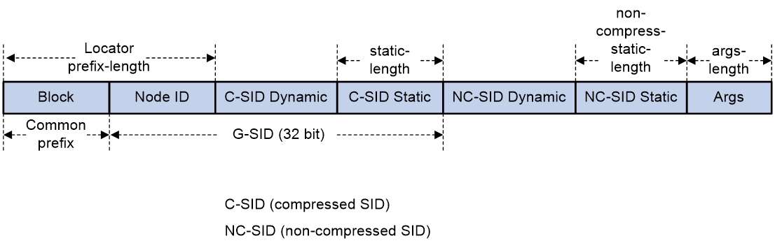
For more flexible allocation of SRv6 SIDs, a new locator type COC-both has been introduced. In a COC-both locator, compressible SID portions and non-compressible SID portions are available. SIDs that carry the COC flavor, for example, End(COC32) and End.X(COC32) SIDs and SIDs that do not carry the COC flavor, for example, End(COCNONE) and End.X(COCNONE) SIDs are dynamically or statically allocated from the compressible SID portions. Only common SIDs, such as End and End.X SIDs are allocated from the non-compressible SID portions. The SRv6 SIDs allocated from different portions are categorized as follows:
· SRv6 SIDs allocated from the static compressible portion.
· SRv6 SIDs allocated from the dynamic compressible portion.
· SRv6 SIDs allocated from the static non-compressible portion.
· SRv6 SIDs allocated from the dynamic non-compressible portion.
Assume that you configure the locator test1 ipv6-prefix 100:200:DB8:ABCD:: 64 common-prefix 48 coc-both non-compress-static 16 static 8 args 16 command.
· The locator is 100:200:DB8:ABCD::. The length is 64 bits.
· The common prefix length is 48 bits. A compressed SRv6 SID does not contain this portion.
· The compressible static portion length is 8 bits.
· The compressible dynamic portion length is 8 bits. This value is calculated by using the following formula: 32 – (prefix-length – common-prefix-length) + compressible-static-length.
· The non-compressible static portion length is 16 bits.
· The non-compressible dynamic portion length is 16 bits. This value is calculated by using the following formula: 128 - common-prefix-length - args-length - 32 - non-compressible-static-length.
· The Args portion length is 16 bits.
In this example, the following static compressible SRv6 SID range and dynamic compressible SRv6 SID range are obtained on the locator:
· The start value for compressible static SRv6 SIDs is 100:200:DB8:ABCD:1::.
· The end value for compressible static SRv6 SIDs is 100:200:DB8:ABCD:FF::.
· The start value for compressible dynamic SRv6 SIDs is 100:200:DB8:ABCD:100::.
· The end value for compressible dynamic SRv6 SIDs is 100:200:DB8:ABCD:FFFF::.
· The following static non-compressible SRv6 SID range and dynamic non-compressible SRv6 SID range are obtained on the locator:
· The start value for static non-compressible SRv6 SIDs is 100:200:DB8:ABCD::1:0.
· The end value for static non-compressible SRv6 SIDs is 100:200:DB8:ABCD::FFFF:0.
· The start value for dynamic non-compressible SRv6 SIDs is 100:200:DB8:ABCD:0:1::.
· The end value for dynamic non-compressible SRv6 SIDs is 100:200:DB8:ABCD:0:FFFF:FFFF:0.
G-SRv6 packet in 32-bit G-SRv6 compression
G-SRv6 packet format
As shown in Figure 9, G-SRv6 can encapsulate both G-SIDs and 128-bit SRv6 SIDs in the segment list of the SRH. It needs to encapsulate four G-SIDs in a group to the original location of a 128-bit SRv6 SID. If the location contains fewer than four G-SIDs (less than 128 bits), G-SRv6 pads the remaining bits with 0s. Multiple consecutive G-SIDs form a compressed path, called a G-SID list. A G-SID list can contain one or more groups of G-SIDs.
|
|
NOTE: If the SRv6 SID of the next node requires compression, the routing protocol adds the Continue of Compression (COC) flag to the advertised SRv6 SID of the local node. The COC flag indicates that the next SRv6 SID is a G-SID. A COC flag only identifies the forwarding behavior of an SRv6 SID, and is not actually carried in the packet. The COC flags in Figure 9 are for illustration purposes only. |
The G-SIDs in the segment list are arranged as follows:
· The SRv6 SID before the G-SID list is a 128-bit SRv6 SID with the COC flag, indicating that the next SID is a 32-bit G-SID.
· Except the last G-SID, all G-SIDs in the G-SID list must carry the COC flag to indicate that the next SID is a 32-bit G-SID.
· The last G-SID in the G-SID list must be a 32-bit G-SID without the COC flag, indicating that the next SID is a 128-bit SRv6 SID.
· The next SRv6 SID after the G-SID list is a 128-bit SRv6 SID that can carry the COC flag or does not carry the COC flag.
Calculating the destination address with G-SID
As shown in Figure 10, G-SRv6 combines the G-SID and Common Prefix in the segment list to form a new destination address.
· Common Prefix—Common prefix address manually configured by the administrator.
· G-SID—Compressed 32-bit SID obtained from the SRH.
· SID Index (SI)—Index that identifies a G-SID in a group of G-SIDs. This field is the least significant two bits of the destination IPv6 address. The value range is 0 to 3. The SI value decreases by 1 at each node that performs SID compression. If the SI value becomes 0, the SL value decreases by 1. In a group of G-SIDs in the segment list, the G-SIDs are arranged from left to right based on SI values. The SI value is 0 for the leftmost G-SID, and is 3 for the rightmost G-SID.
· 0—If the total length of the Common Prefix, G-SID, and SI portions is less than 128 bits, the deficient bits are padded with 0s before the SI portion.
Figure 10 Destination address calculated with G-SID
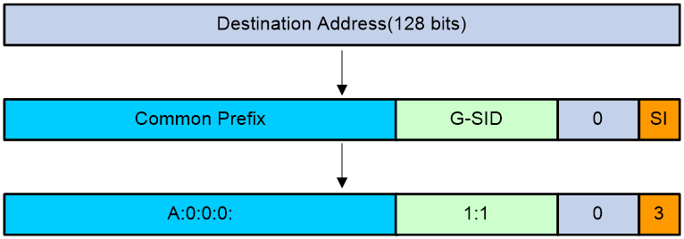
Suppose the following conditions exist:
· The Common Prefix deployed on the SRv6 node is A:0:0:0::/64.
· The G-SID in the SRv6 packet is 1:1.
· The SI value associated with the G-SID is 3.
Based on the previous conditions, the device calculates the destination address as A:0:0:0:1:1::3.
Upon receiving the G-SRv6 packet, the SRv6 node calculates the destination address for the packet as follows:
· If the destination address of the packet is a 128-bit SRv6 SID with the COC flag in the segment list, the next SID is a G-SID. The device decreases the SI value by 1 and searches for the G-SID group corresponding to [SI-1]. Then, the device calculates the destination address based on the 32-bit G-SID identified by SI value 3.
· If the destination address of the packet is a 32-bit SRv6 SID with the COC flag in the segment list, the next SID is a G-SID.
¡ If the SI value is larger than 0, the device decreases the SI value by 1 and searches for the G-SID group corresponding to SL value of the packet. Then, the device calculates the destination address based on the 32-bit G-SID identified by [SI-1].
¡ If the SI value is equal to 0, the device decreases the SL value by 1, resets the SI value to 3, and searches for the G-SID group corresponding to the SL value of the packet. Then, the device calculates the destination address based on the 32-bit G-SID identified by SI value 3.
· If the destination address of the packet is a 32-bit SRv6 SID without the COC flag in the segment list, the device decreases the SL value by 1 and searches for the 128-bit SRv6 SID corresponding to [SL-1]. Then, the device replaces the destination address in the IPv6 header with the SRv6 SID.
· If the destination address of the packet is a 128-bit SRv6 SID without the COC flag in the segment list, the device decreases the SL value by 1 and searches for the 128-bit SRv6 SID corresponding to [SL-1]. Then, the device replaces the destination address in the IPv6 header with the SRv6 SID.
16-bit G-SRv6 compression
Basic concepts
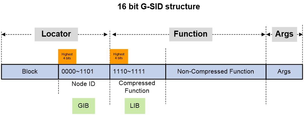
G-SID format
As shown in Figure 11, in 16-bit G-SRv6 compression, an SRv6 SID contains the Locator, Function, and Arguments portions.
The locator portion of an SRv6 SID contains the Block and Node ID portions.
· Block—Common prefix, also known as Locator Block, is redundant information in a G-SRv6 packet. Its length is the total length of the locator portion (prefix-length) minus 16 bits.
· Node ID—Identifies a node, also known as Locator Node. It has a fixed length of 16 bits. The Node ID is advertised to all nodes within the SRv6 domain along with the locator through IGP. After learning the routing prefix that contains the Block and Node ID, other nodes can forward SRv6 packets based on the Block and Node ID.
The Function portion of an SRv6 SID is only used locally to guide packet forwarding and is only locally significant. The Function portion is divided into Compressed Function and Non-Compressed Function portions.
· Compressed Function—This portion has a fixed length of 16 bits. G-SIDs that carry COC and NEXT flavors can be allocated from this portion. This portion contains the dynamic compressed G-SID (dynamic portion) and static compressed G-SID (static portion, where the length of the static portion can be specified in the CLI).
· Non-Compressed Function—Common SRv6 SIDs that do not carry the COC flavor are allocated from this portion.

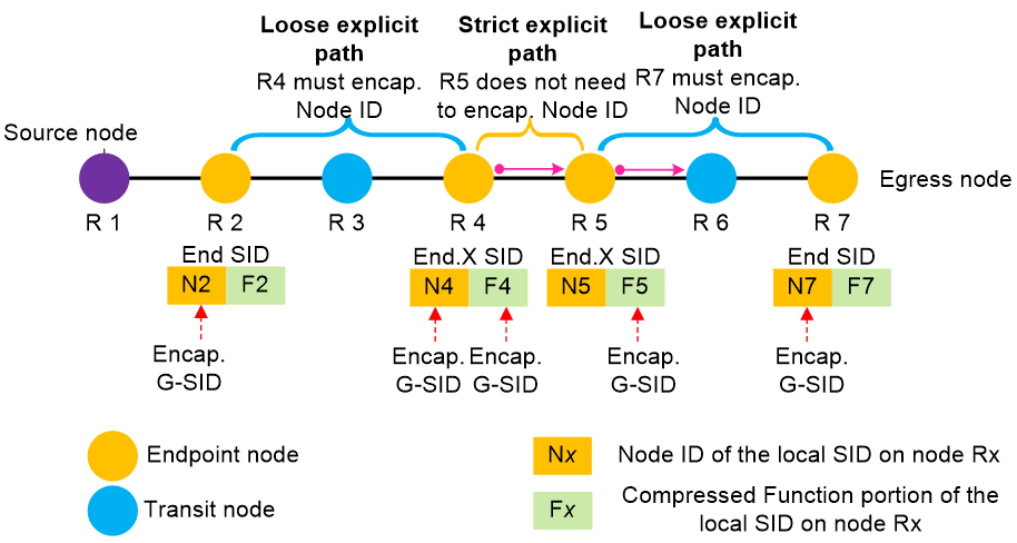
Strict explicit path and loose explicit path
Typically, SRv6 SIDs with the same common prefix can be compressed when an SRv6 endpoint node encapsulates either the 16-bit Node ID or the 16-bit compressed Function portion as G-SIDs into an G-SRv6 packet.
An SRv6 endpoint node can encapsulate the 16-bit Node ID portion of the local SRv6 SID or the 16-bit compressed Function portion as a G-SID into an G-SRv6 packet, or encapsulate both the Node ID and the compressed Function portions into a G-SRv6 packet. As shown in Figure 12, the encapsulation mode depends on the actual scenario:
· Loose explicit path—A scenario where packets cannot be forwarded to the current node based on the SID of the previous hop (for example, R2 to R4 and R5 to R7 shown in Figure 12). Assume that on an SRv6 forwarding path, there are two non-adjacent endpoint nodes, and the previous node of the current node cannot forward packets to the current node even if it uses an End.X G-SID. In this case, you must configure the device to encapsulate the Node ID in the local SID of this node when it encapsulates a G-SID for routing purposes. You can determine whether configure the device to encapsulate the Function portion of the local SID to control the forwarding behavior as needed.
· Strict explicit path scenario—A scenario where packets can be forwarded to a node based on the SID of the previous hop for that node (for example, R4 to R5 shown in Figure 12). Assume that the previous hop for a node uses a local End.X G-SID to indicate the forwarding path, and the packet can be forwarded to this node based on the next hop and outgoing interface of the End.X G-SID. In this case, only the compressed Function portion of the local SID of this node needs to be encapsulated, enabling the packet to be forwarded according to the forwarding behavior bound to the compressed Function portion of the local SID.
Figure 12 Strict explicit path and loose explicit path
Container for G-SIDs
In a G-SRv6 packet, a container is a 128-bit space used to store G-SIDs. The 128-bit destination address in the IPv6 basic header of a G-SRv6 packet can be used as a container to store multiple G-SIDs. Each 128-bit SID in the SRH extension header can also be used as a container.
GIB and LIB
H3C uses the Global Identifiers Block (GIB) and Local Identifiers Block (LIB) to distinguish between a Node ID and compressed Function portion encapsulated as a 16-bit G-SID into a G-SRv6 packet.
As shown in Figure 13, two non-overlapping subspaces GIB (global G-SID space) and LIB (local G-SID space) are scoped based on the 16 different values of the highest 4 bits of a 16-bit G-SID.
· In the GIB, a G-SID is the Node ID in the local SID of an endpoint node. By default, the highest 4 bits of a G-SID in the GIB are set to 0x0 to 0xD (binary 0000 to 1101, 14 in total), indicating that the G-SID is the Node ID in the local SID of an endpoint node. The G-SID is used for IP addressing by the endpoint node.
· In the LIB, a G-SID is the Function portion in the local SID of an endpoint node. By default, the highest 4 bits of a G-SID in the LIB are set to 0xE to 0xF (binary 1110 to 1111, 2 in total), indicating that the G-SID is the compressed Function portion in the local SID of an endpoint node. The G-SID is used to identify different forwarding behaviors of the endpoint node.
By default, the ratio of G-SIDs between the GIB and LIB is 14:2. You can change this ratio in the CLI.
COC16 locators
To allocate 16-bit compressed G-SIDs, H3C has defined a COC16 locator. 16-bit compressed G-SIDs can be allocated from the address space of the COC16 locator. Based on G-SID allocation methods and the flavors carried by G-SIDs, COC16 locators in three different modes have been defined, as shown in Figure 14.
· COC16 locator in default mode—The device can allocate G-SIDs that carry COC, NEXT, and COC and NEXT flavors and SIDs that do not carry COC flavors (COC-none) from the compressible Function portion in a COC16 locator in default mode. Additionally, the device can allocate common SIDs that do not carry COC or NEXT flavors from the non-compressible Function portion. COC16 locators in default mode have the most SID types and flavors that can be allocated.
· COC16 locator in next mode—The only difference between a COC16 locator in default mode and in next mode is that only SIDs that carry the NEXT flavor can be allocated from a COC16 locator in next mode. Only G-SIDs that support the move action can be allocated from a COC16 locator in next mode, and is used only for interoperation with 16-bit G-SRv6 compression from third-parties.
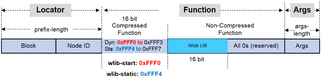
· COC16 locator in W-LIB mode—In the 16-bit compression G-SRv6 scheme, the G-SIDs in the 16-bit Function portion must be bound to different endpoint behaviors and the address space of the Function portion might be insufficient. To address this issue, H3C introduced COC16 locators in W-LIB mode. In this type of locator, the highest 16 bits of the uncompressed Function portion are used to expand the available address space of the compressed Function portion. This expanded 16-bit address space is called the Wide LIB (W-LIB).
The next G-SID will be allocated from the W-LIB of the COC16 locator in W-LIB mode only when the compressed Function portion in a G-SRv6 packet is set to eight specific values (configurable in the CLI). Assume that a compressed Function portion is encapsulated in a G-SRv6 packet, with a value in the range of 0xFFF0 to 0xFFF7, indicating that the next 16-bit G-SID is allocated from the W-LIB. When the packet is forwarded, the system combines the compressed Function portion with the G-SID from the W-LIB to look up in the local SID table and forward the packet.
· For a COC 16 locator in W-LIB mode, G-SIDs that carry the NEXT flavor can be allocated from the W-LIB or from the compressed Function portion. In addition, SIDs that do not carry the COC flavor (COC-NONE) can be allocated from the compressed Function portion. If G-SIDs are allocated from the compressed Function portion, the values for the Function portion will be values other than 0xFFF0 through 0xFFF7.
You can use the locator command to specify the start value for the compressed Function portion or the start value of a static portion. For example, if you set wlib-start to 0xFFF0, you set the start value for the compressed Function portion. If you set wlib-start to 0xFFF4, you set the start value for a static portion in the compressed Function portion. G-SIDs in the W-LIB identified by 0xFFF0 to 0xFFF3 are allocated dynamically, and G-SIDs in the W-LIB identified by 0xFFF4 to 0xFFF7 are statically allocated.
In the current software version, COC16 locators in W-LIB mode are used to allocate VPN SIDs for both L3VPN and L2VPN services.
Figure 14 COC16 locator in W-LIB mode
16-bit G-SRv6 compression classification
The following 16-bit compression schemes are available depending on the encapsulation and forwarding modes of SRv6 packets:
· Combination of NEXT and COC flavors—Multiple G-SIDs encapsulated in a G-SRv6 packet carry both COC and NEXT flavors, and the device performs the move or replace actions when it forwards the packet. This scheme offers higher compression efficiency for packet encapsulation. However, all endpoint nodes on the forwarding path must have the same Block (common prefix). If the Block changes, a new container that carries the new Block must be encapsulated, reducing compression efficiency.
· NEXT flavor only—Multiple G-SIDs encapsulated in a G-SRv6 packet carry only the NEXT flavor, and the device performs the move action when it forwards the packet. Although this scheme sacrifices some packet encapsulation compression efficiency, endpoint nodes along the forwarding path can have different Blocks, allowing for more flexible planning of common prefix addresses.
· COC flavor only—Multiple G-SIDs encapsulated in a G-SRv6 packet carry only the COC flavor, and the device performs the replace action when it forwards the packet. The packet encapsulation and forwarding process of this scheme is similar to the 32-bit G-SRv6 compression scheme. G-SID are encapsulated only in the SID list of the SRH header, and the destination IPv6 address is no longer used as the first container for encapsulating the G-SIDs. Therefore, this scheme provides a lower compression efficiency.
You can select the schemes as needed.
16-bit compression with a combination of NEXT and COC flavors
G-SRv6 packet encapsulation in 16-bit compression
Packet encapsulation in the 16-bit compression scheme is controlled by the configuration of the index command. Incorrect planning of G-SIDs or incorrect configuration for the index command can cause discrepancies in G-SRv6 packet encapsulation or even failure of packet encapsulation. The following uses the index command to describe the packet encapsulation procedure.
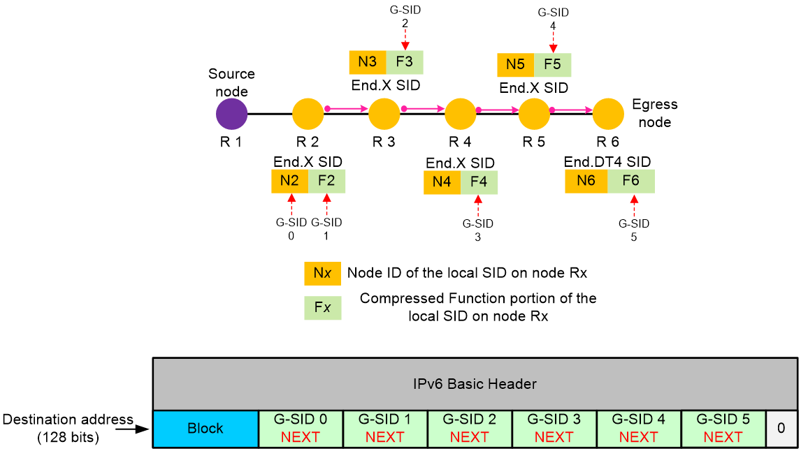
As shown in Figure 15, a packet is forwarded along the path from R1 to R6, with fewer nodes. The total length of the 16-bit G-SIDs and the Block of all nodes does not exceed 128 bits, and the flag field and the SRH TLV are not required. In such cases, the source node can directly encapsulate the Block and the G-SID list into the destination address field of the IPv6 basic header, without encapsulating an SRH extension header. Any space less than 128 bits in the container is padded with zeros. The G-SIDs are encapsulated from left to right in order of proximity to the source node. When you configure the index command, you must specify the coc-next or next keyword for G-SID 0 through G-SID 5, indicating that G-SIDs 0 through 5 are 16-bit compressed G-SIDs.
Figure 15 G-SRv6 packet encapsulation
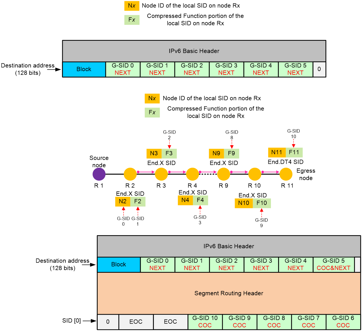
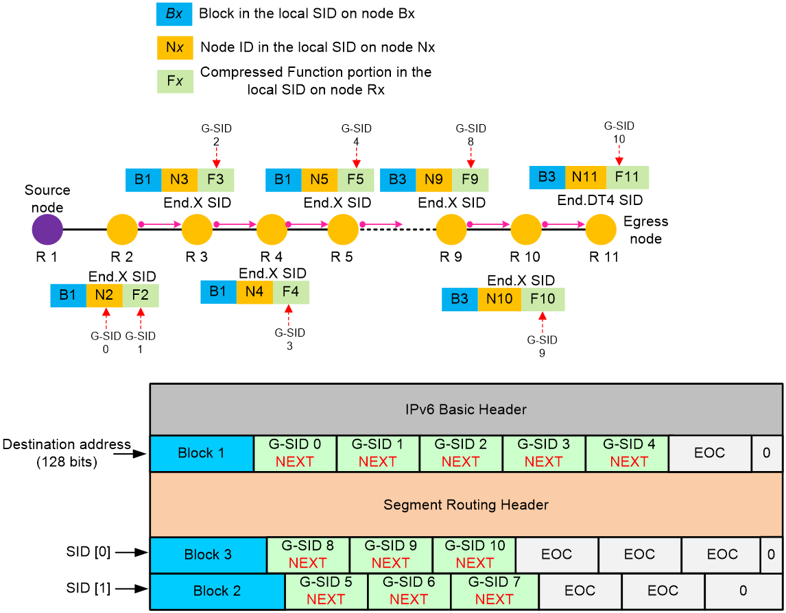
As shown in Figure 16, a packet is forwarded along the path from R1 to R11, with many nodes on the path. The total length of the 16-bit G-SIDs and the Block for all nodes has exceeded 128 bits, and a single container cannot store all G-SIDs. In this case, the source node can encapsulate the Block and the G-SID list in the destination address of the IPv6 basic header. The G-SIDs that exceed 128 bits must be encapsulated in the SID list of the SRH extension header. In the first container of the SID list, the Block does not need to be encapsulated. The G-SIDs are encapsulated from right to left in order of proximity to the source node. When you configure the index command, you must specify the coc-next or next keyword for G-SID 0 to G-SID 4. For the last G-SID G-SID 5 in the container, its next SID is still a 16-bit compressed G-SID. Therefore, this G-SID must carry the COC flavor, and you must specify the coc-next or next keyword in the index command. For G-SID 6 to G-SID 9, the next G-SID for each G-SID is also a 16-bit compressed G-SID. Therefore, you must specify the coc-next or next keyword in the index command. Whether the last G-SID G-SID 10 in the SID list carries the COC flavor depends on whether the next SID is a compressed G-SID. Spaces that are shorter than 128 bits in the container are filled with zeros. A space with consecutive 16-bit zeros is called End of Container (EOC), which indicates that there are no valid G-SIDs in the subsequent space of the current container.
Figure 16 G-SRv6 packet encapsulation
G-SRv6 packet forwarding
The following uses the scenario shown in Figure 17 as an example to describe the package forwarding process. G-SRv6 packets can be forwarded correctly only when local endpoint nodes are configured with appropriate flavors.
G-SRv6 packet forwarding proceeds as follows:
1. On source node R1, after the G-SRv6 packet is encapsulated, R1 searches the routing table based on the destination address of the IPv6 packet. It matches the longest mask and detects that Block+G-SID 0 is the locator network segment for R2. Therefore, the packet is forwarded to node R2 through the output interface and next hop in the routing table.
2. Node R2 matches the longest mask and detects that Block+G-SID 0+G-SID 1 is the local End.X SID and the SID carries the NEXT flavor. Therefore, the node performs the move action. As shown in Figure 17, it moves the G-SIDs following G-SID 1 in the container to right after the Block, and fills the last few bits with 0s to generate an EOC. R2 forwards the packet to node R3 through the output interface bound to the End.X SID.
3. For all endpoints on the forwarding path, a special local G-SID entry exists. Different from a common local SID, a G-SID in the local G-SID entry can be generated by the Block + compressed Function portion or the Block + compressed Function portion + W-LIB, without the need for a Node ID. Node R3 matches the longest mask and detects that the destination address Block + G-SID 2 is a local G-SID entry with an End.X bound, and the G-SID carries the NEXT flavor. Therefore, R3 moves all the other G-SID after G-SID 2 in the container to after the Block. The last few bits of the container are filled with 0s to generate an EOC. R3 forwards the packet to node R4 through the outbound interface bound to the End.X SID.
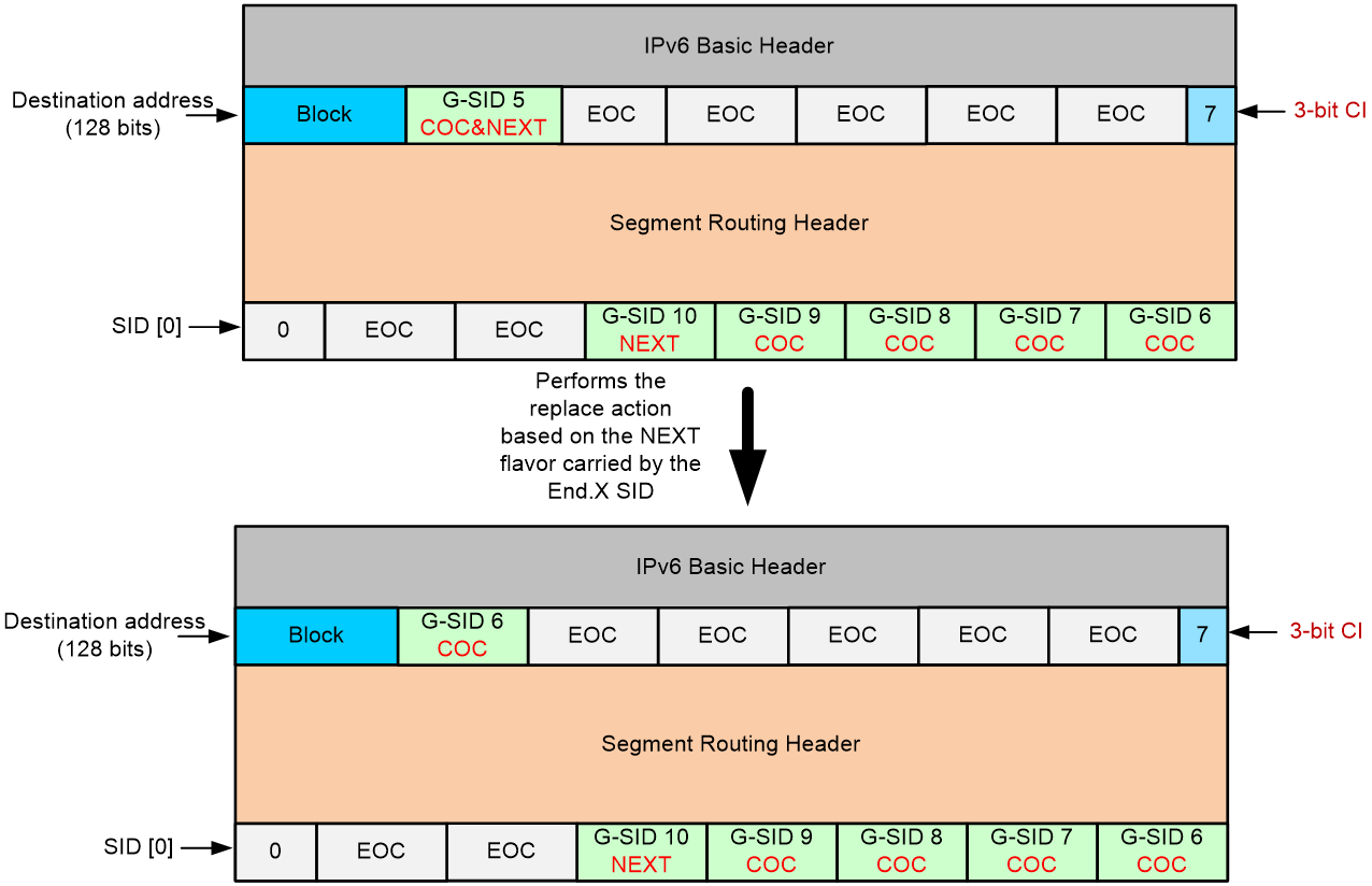
4. Nodes R4 and R5 repeat the previous steps until the G-SRv6 packet is forwarded to node R6. R6 finds that the IPv6 destination address Block + G-SID 5 matches the longest mask rule in the local G-SID table and carries the COC flavor, indicating that the next SID is still a 16-bit compressed G-SID. G-SID 5 is the last G-SID in the current container, followed by an all-zero EOC. As shown in Figure 17, R6 uses the last 3 bits of the destination address as the Compressed-SID Index (CI) flag, setting the value to 7. CI identifies the position of G-SID 6 within the container, with a value in the range of 0 to 7. R6 then performs the replace action according to the COC flavor. It extracts the 16-bit G-SID 6 from the SID[0] container and replaces it in the destination address block. Finally, R6 forwards the packet from the output interface to R7 based on the End.X behavior bound to Block + G-SID 5.
5. Nodes R7 to R10 repeat the steps performed by R6 until the G-SRv6 packet reaches R11. R11 is the egress node, and G-SID 10 is the last SID in the container. The SL is now 0. Therefore, R11 stops processing the SRv6 packet, decapsulates the SRv6 packet based on the forwarding behavior associated with G-SID 10, looks up in the VPN routing table, and forwards the decapsulated packet to the VPN. If the forwarding behavior of G-SID 10 is End or End.X, the SL is greater than 0, and G-SID 10 carries the COC flavor, R11 sets CI to 2. CI identifies the position of an all-zero EOC, indicating the end of the current container. Therefore, the node decreases the SL by 1, sets the CI to 7, and then retrieves the G-SID from the corresponding position in the next container. If G-SID 10 does not carry a COC flavor, the next SID is a common 128-bit SID, and the packet is forwarded through the general SRv6 packet forwarding process.
Figure 17 Execution of the move action based on the NEXT flavor carried by the SID
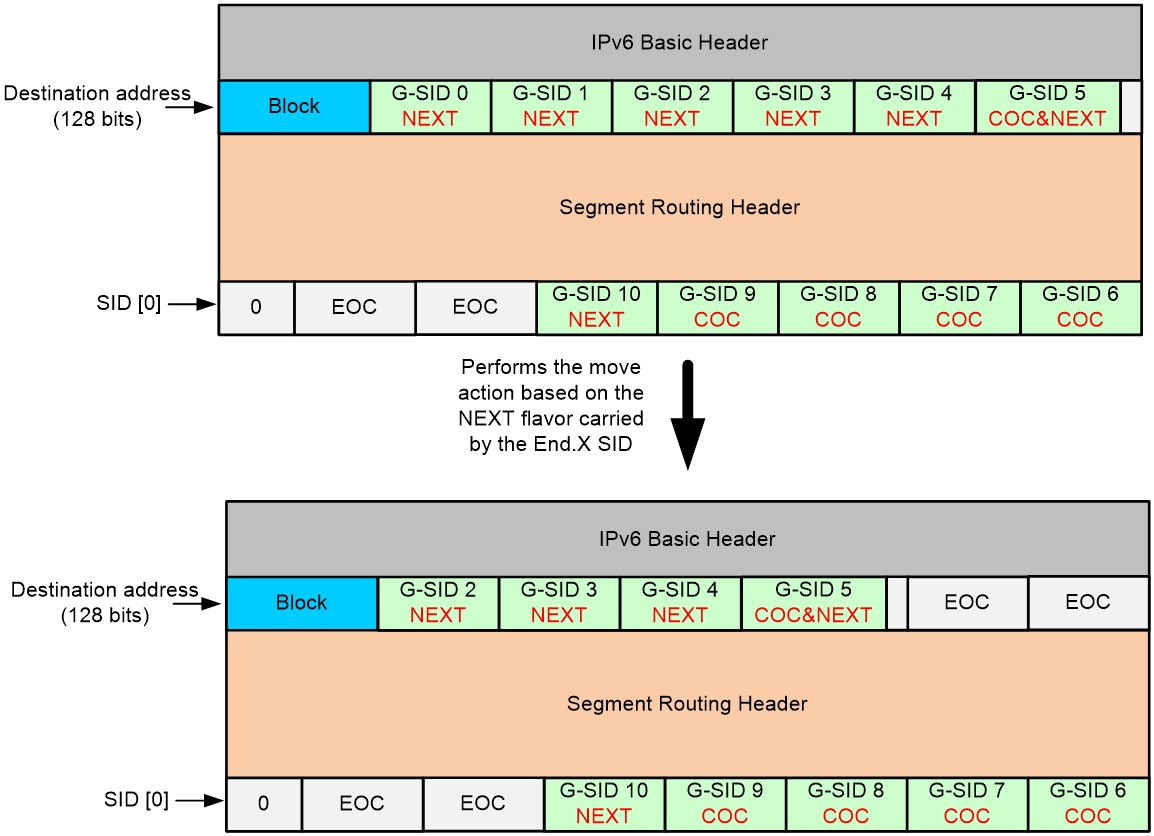
Figure 18 Execution of the replace action based on the COC flavor carried by the SID
16-bit compression scheme where only the NEXT flavor is supported
G-SRv6 packet encapsulation
This scheme is similar to the 16-bit G-SRv6 compression scheme with a combination of NEXT and COC flavors. The following uses the index command to describe the packet encapsulation procedure.
Similar to scheme 1, if there are fewer forwarding nodes and they share the same Block, the G-SID and Block can be encapsulated in the destination address of the IPv6 header, eliminating the need for SRH encapsulation. However, if there are many nodes on the forwarding path or the nodes have different Blocks, the SRH header must be encapsulated.
As shown in Figure 19, three different Blocks exist on nodes R1 through R11. The Blocks for nodes R2 through R5, R6 through R8, and R9 through R11 are Block 1, Block 2, and Block 3, respectively. When the device encapsulates a G-SRv6 packet, it must encapsulate the three Blocks in different containers. When you configure the index command, you must specify the coc-next or next keyword for G-SIDs 0 through 3, G-SIDs 5 through 6, and G-SIDs 8 through 9 to ensure that the G-SIDs are encapsulated in the containers with Blocks from left to right in order. For the next G-SID to be encapsulated correctly, do not specify the coc or coc-next keyword for the last G-SID in each container. Spaces that are shorter than 128 bits in the container are filled with zeros to generate an EOC.
Figure 19 G-SRv6 packet encapsulation
G-SRv6 packet forwarding
The following uses the scenario shown in Figure 19 as an example to describe the package forwarding process. G-SRv6 packets can be forwarded correctly only when a local endpoint node is configured with SIDs that carry appropriate flavors.
In this scheme, only the move action is taken in G-SRv6 packet forwarding. The packet forwarding process is as follows:
1. On source node R1, after the G-SRv6 packet is encapsulated, R1 searches the routing table based on the destination address of the IPv6 packet. Using the longest mask match rule, R1 detects that Block 1+G-SID 0 is the locator network segment for R2. Therefore, it forwards the packet to node R2 through the output interface and next hop in the routing table.
2. Using the longest mask match rule, node R2 detects that Block+G-SID 0+G-SID 1 is a local End.X SID and the SID carries the NEXT flavor. Therefore, the node performs the move action to move the G-SIDs following G-SID 1 in the container to after Block 1, and fills the last few bits with 0s to generate an EOC. R2 forwards the packet to node R3 through the output interface bound to the End.X SID.
3. For all endpoints on the forwarding path, a special local G-SID entry exists. Different from a common local SID, a G-SID in the local G-SID entry can be generated by the Block + compressed Function portion or the Block + compressed Function portion + W-LIB, without requiring a Node ID. Node R3, according to the longest mask match rule, detects that the destination address Block + G-SID 2 is a local G-SID entry with the End.X behavior bound, and the G-SID carries the NEXT flavor. Therefore, R3 moves all the other G-SIDs after G-SID 2 in the container to after the Block and fills the last few bits of the container with 0s to generate an EOC. R3 forwards the packet to node R4 through the outbound interface bound to the End.X SID.
4. Node R4 repeats the previous steps until the G-SRv6 packet is forwarded to node R5. Using the longest mask match rule, R5 detects that the IPv6 destination address Block + G-SID 4 is a local G-SID entry and the G-SID does not carry a COC flavor, indicating that the next SID is still a 16-bit compressed G-SID. G-SID 4 is the last G-SID in the current container, followed by an all-zero EOC. At this point, the SL is 1. R5 updates SID[1] to the destination address and decreases the SL by 1. Finally, R6 forwards the packet from the output interface to R6 based on the End.X behavior associated with Block + G-SID 4.
5. Nodes R6 to R10 repeat the previous forwarding steps until the G-SRv6 packet reaches R11. R11 is the egress node, and G-SID 10 is the last SID in the container. The SL is now 0. Therefore, R11 stops processing the SRv6 packet, decapsulates the SRv6 packet based on the forwarding behavior associated with G-SID 10, looks up in the VPN routing table, and forwards the decapsulated packet to the VPN.
16-bit compression scheme where only the COC flavor is supported
G-SRv6 packet encapsulation
This scheme is similar to the 16-bit G-SRv6 compression scheme with a combination of NEXT and COC flavors. The following uses the index command to describe the packet encapsulation procedure.
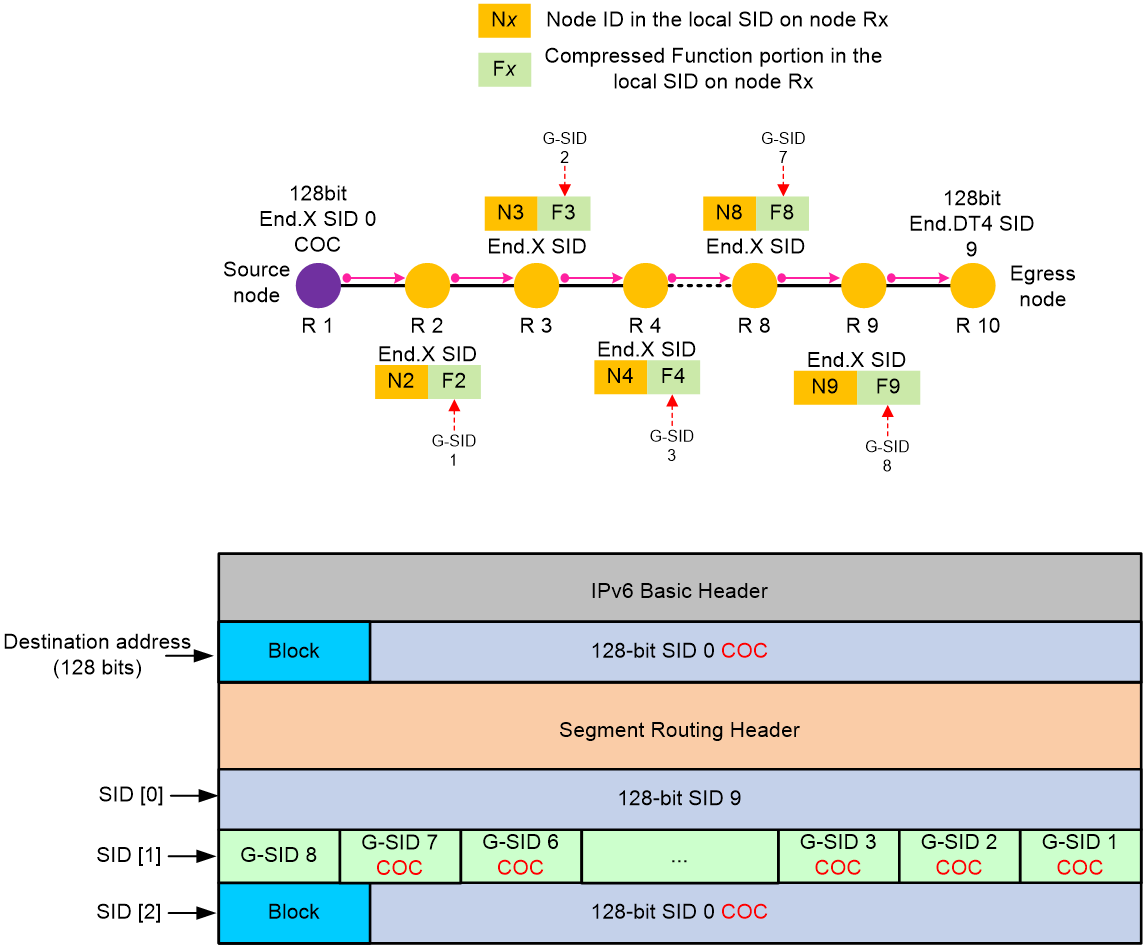
As shown in Figure 20, when you execute the index command for G-SRv6 packet encapsulation on source node R1, you must specify the coc keyword for the first SID SID 0 in the SID list to carry the COC flavor without compression. coc identifies the next SID as 16-bit G-SID 1, which must be compressed and placed in the next container. For G-SIDs 1 through 7, each G-SID's next SID is also a 16-bit compressed G-SID. Therefore, you must specify the coc or coc-next keyword for these G-SIDs. These G-SIDs are encapsulated in the next container from right to left, in order of proximity to the source node. If a container is not fully occupied by G-SIDs, any space less than 128 bits is filled with zeros. A 16-bit block of zeros is called End of Container (EOC), which indicates that there are no valid G-SIDs in the subsequent space of the current container. Whether the last G-SID G-SID 8 in the SID list carries the COC flavor depends on whether the next SID is a 16-bit compressed G-SID. In the figure, the coc keyword is specified for G-SID 8, indicating that the next SID SID 9 is a common 128-bit End.DT4 SID.
Figure 20 G-SRv6 packet encapsulation
G-SRv6 packet forwarding
The following uses the scenario shown in Figure 20 as an example to describe the packet forwarding process. G-SRv6 packets can be forwarded correctly only when local endpoint nodes are configured with appropriate flavors.
In this scheme, only the replace action is taken in G-SRv6 packet forwarding. The packet forwarding process is as follows:
1. After encapsulating the G-SRv6 packet, source node R1 with the SL as 2 replaces the destination address with SID[2]. Using the longest mask match rule, it detects that End.X SID 0 is a local SID that carries the COC flavor, indicating that the next SID is a 16-bit compressed G-SID, and SID 0 is the last SID in the current container. Therefore, R1 uses the last 3 bits of the destination address as the CI, and sets the value to 7. CI identifies the position of G-SID 1 within the container, with a value in the range of 0 to 7. R1 performs the replace action to extract the 16-bit G-SID 1 from SID[1] in the container and place it in the Block after the destination address. Finally, R1 forwards the packet to node R2 through the output interface and next hop bound to End.X SID 0.
2. Using the longest mask match rule, Node R2 detects that Block+G-SID 1 is the local End.X SID. This SID carries the COC flavor, indicating that the next SID is a 16-bit compressed G-SID. At this point, CI=7. R2 decreases the CI value by 1 and performs the replace action to extract G-SID 2 from the position indicated by CI and place it after the Block in the destination address. Then, R2 forwards the packet to node R3 through the output interface bound to the End.X SID.
3. Nodes R3 to R8 repeat the forwarding behavior of node R2 until the packet reaches node R9, where CI=0, indicating that G-SID 8 is the last G-SID in the container. G-SID 8 does not carry a COC flavor, indicating that the next SID 9 is a 128-bit common SID. At this point, SL-1=0. R9 copies SID[0] to the destination address of the IPv6 packet and forwards the packet to node R10 through the output interface bound to G-SID 8.
4. R10 is the endpoint node and the SL=0. Therefore, it stops processing the SRv6 packet, decapsulates the SRv6 packet based on forwarding behavior End.DT4 associated with SID 9, looks up in the VPN routing table, and forwards the decapsulated packet to the VPN.
|
|
IMPORTANT: The three 16-bit compression G-SRv6 packet encapsulation and forwarding schemes, the 32-bit G-SRv6 compression scheme, and the non-compression SRv6 packet encapsulation scheme can be used together. How SRv6 packets are encapsulated and forwarded depends on actual service requirements, configuration of the index command, and local SID configuration. This section only lists three significantly different and mainstream G-SRv6 packet encapsulation and forwarding schemes in 16-bit G-SRv6 compression. |
BGP-EPE
About BGP-EPE
Advertising SRv6 SIDs through IGP can only implement orchestration of SIDs within an AS for optimal traffic forwarding based on the SID list. However, in large-scale networks across multiple ASs, using IGP for SRv6 cannot orchestrate SIDs to form a complete inter-AS traffic forwarding path across ASs. At this point, an extension of BGP for SRv6 is required for inter-AS SID allocation and advertisement.
BGP Egress Peer Engineering (BGP-EPE) is an extension of BGP for SRv6. It can allocate BGP peer SIDs to inter-AS segments. Peer SIDs are advertised to the SDN controller through extended BGP LS messages. The SDN controller orchestrates the IGP SIDs and BGP peer SIDs to generate inter-AS packet forwarding paths. Typically, in an inter-AS network, each AS requires at least one but not all forwarding devices to establish a BGP LS peer relationship with the SDN controller. The forwarding devices that have established a BGP LS peer relationship with the SDN controller collect all IGP SIDs and BGP peer SIDs within the AS and advertise them to the SDN controller through BGP LS messages, completing collection of network-wide information.
Operating mechanism
BGP-EPE supports automatic peer SID allocation and static peer SID allocation. As shown in Figure 21, BGP-EPE can allocate the following peer SIDs:
· PeerNode SID—A BGP-EPE peer that identifies a peer node. BGP-EPE allocates a PeerNode SID to each BGP peer. If the device establishes EBGP peer relationship with a peer through a loopback interface, multiple physical links might exist between BGP-EPE peers. In this case, the PeerNode SID for this peer is associated with multiple output interfaces. Traffic destined for this peer based on the PeerNode SID will be distributed among these output interfaces.
· PeerAdj SID—Identifies an adjacency link that can reach a BGP-EPE peer. If the device establishes EBGP peer relationship with a peer through a loopback interface, multiple physical links might exist between BGP-EPE peers. Each link is allocated a PeerAdj SID. When the device forwards traffic based on a PeerAdj SID, the traffic is forwarded out of the interface that is attached to the link identified by the PeerAdj SID.
· PeerNode-Adj SID—Identifies a peer node and identifies one or multiple adjacency links that can reach a peer node.
· PeerSet SID—Identifies a group of peer nodes in a BGP-EPE SRv6 peer set. A PeerSet SID corresponds to multiple PeerNode SIDs and PeerAdj SIDs. When the device forwards traffic based on a PeerSet SID, it distributes the traffic among multiple peers.
Figure 21 BGP-EPE network diagram

As shown in Figure 21, BGP-EPE allocates peer SIDs as follows:
· ASBR 1 and ASBR 3 have two direct physical links. They establish EBGP peer relationship through loopback interfaces. On ASBR 1, BGP-EPE allocates PeerNode SID 100:AB::1 to ASBR 3 and allocates PeerAdj SIDs 100:AB:1::2 and 100:AB:1::3 to the physical links. When ASBR 1 forwards traffic to ASBR 3 based on the PeerNode SID, the two physical links load share the traffic.
· EBGP peer relationship has been established between ASBR 1 and ASBR 5, between ASBR 2 and ASBR 4, and between ASBR 2 and ASBR 5 through directly connected physical interfaces. On ASBR 1, BGP-EPE allocates PeerNode SID 100:AB::2 to ASBR 5. On ASBR 2, BGP-EPE allocates PeerNode SIDs 100:AB::4 and 100:AB::5 to ASBR 4 and ASBR 5, respectively.
· ASBR 4 and ASBR 5 each has established EBGP peer relationship with ASBR 2. On ASBR 2, peers ASBR 4 and ASBR 5 are added to a peer set. BGP-EPE allocates PeerSet SID 100:AB::3 to the peer set. When ASBR 2 forwards traffic based on the PeerSet SID, the traffic is distributed to both ASBR 4 and ASBR 5 for load sharing.
The SIDs allocated to peers by BGP-EPE are not advertised to the peers. Route types used by the peers do not affect BGP-EPE.
BGP virtual links
As shown in Figure 22, the controller can orchestrate IGP SIDs and BGP peer SIDs assigned by BGP-EPE for inter-AC paths based on the link information reported by BGP-LS to generate inter-AS forwarding paths. Typically, Device A and Device B in different ASs are directly connected and they establish EBGP peer relationships through directly connected interfaces. In this case, the local address in the BGP-LS Link NLRI reported by Device A to the controller is 100::1, and the remote address is the next hop 100::2. Device B's local address is 100::2, and the remote address is the next hop 100::1. The controller detects that the remote addresses advertised by Device A and Device B belong to the same network segment, and Device A's local address matches Device B's remote address. Therefore, the controller creates a direct inter-AS link, and orchestrates SIDs based on this link to form a complete inter-AS traffic forwarding path.
Device A and Device D, which are indirectly connected across different ASs, establish EBGP peer relationships through loopback interfaces. The local address in the BGP-LS Link NLRI reported by Device A to the controller is the loopback interface address 1::1, and the remote address is the next hop 100::2 towards the remote loopback interface. Device D's local address is 4::4, and the remote address is 200::1. In this case, Device A and Device D's remote addresses belong to different network segments, and Device A's local address does not match Device D's remote address. Therefore, the controller cannot create a complete inter-AS link based on the address information in the BGP-LS Link NLRI.
Figure 22 Network diagram for BGP virtual link
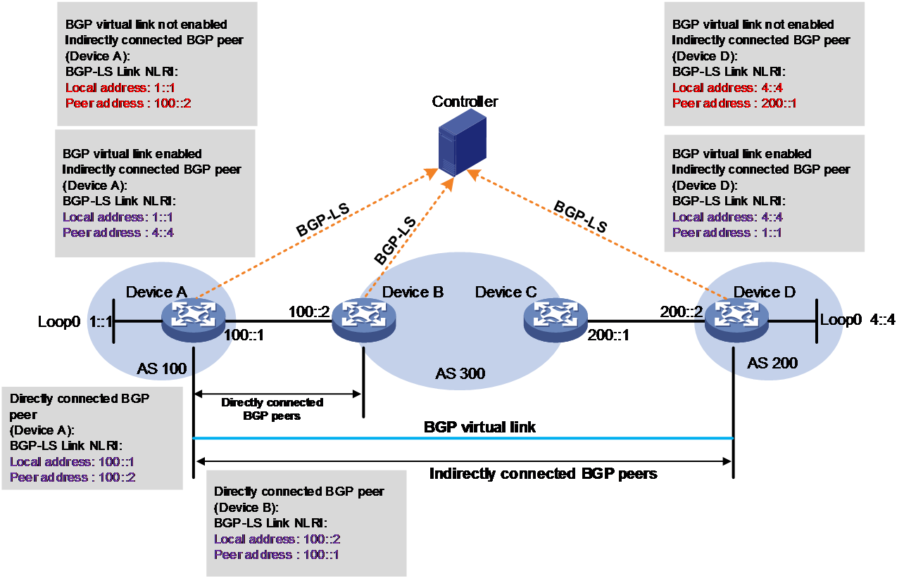
For the controller to orchestrate SIDs and create a complete inter-AS link for the two indirectly connected devices Device A and Device D, you can configure a BGP virtual link. When this feature is enabled, the local address in the BGP-LS Link NLRI reported by Device A to the controller is the loopback interface address 1::1, and the remote address is 4::4, address of the loopback interface on Device D. The local address in the BGP-LS Link NLRI reported by Device D to the controller is local address 4::4, and the remote address is 1::1. The controller can create a reachable virtual link.
BGP-LS advertisement of link attribute information
In an AS, the extended IGP protocol can carry link attribute information. With the link attribute information, devices running the IGP protocol can use the Constraint-based Shortest Path First (CSPF) algorithm to implement TE capabilities.
In scenarios where the controller calculates optimal inter-AC paths, link attributes of intra-AS and inter-AS links are required to implement TE capabilities. Therefore, BGP-LS uses Link Attribute TLVs to carry various link attribute information. Figure 23 shows some of the link attribute information in an Link Attribute TLV.
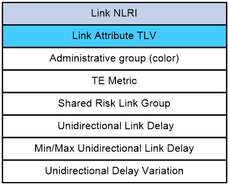
Table 1 Link Attribute TLV description
|
Field |
Description |
|
Link NLRI |
Link Network Layer Reachability Information (NLRI). This information can contain Link Attribute TLVs. |
|
Link Attribute TLV |
Link Attribute TLV type. Options include: · Administrative group (color)—Affinity attribute value, which indicates the color of links. The TLV Type code is 1088. · TE Metric—The TLV Type code is 1092. · Shared Risk Link Group—A set of links that share a resource. The TLV Type code is 1096. · Unidirectional Link Delay—The TLV Type code is 1114. · Min/Max Unidirectional Link Delay—The TLV Type code is 1115. · Unidirectional Delay Variation—The TLV Type code is 1116. |
Topology-Independent Loop-Free Alternate Fast Re-Route (TI-LFA FRR)
Topology-Independent Loop-Free Alternate Fast Re-Route (TI-LFA FRR) provides link and node protection for SRv6 tunnels. When a link or node fails, TI-LFA FRR switches the traffic to the backup path to ensure continuous data forwarding.
TI-LFA FRR background
To minimize traffic loss during the route reconvergence process in SR-MPLS, you can enable the FRR feature on the device directly connected to the protected link or node. The device enabled with FRR is called the Point of Local Repair (PLR). The PLR calculates the shortest path to the destination and calculates an FRR backup path at the same time, and then writes the information into the FIB table. When a protected link or node fails, traffic is rerouted through the FRR backup path on the PLR node, without the need for the network topology to reconverge, significantly reducing traffic loss. FRR has the following mechanisms:
· Loop-Free Alternate Fast Reroute (LFA FRR)—To calculate the backup path, LFA FRR identifies a protected neighboring node (LFA node) of the PLR, enabling traffic to be forwarded to the destination node without passing through the protected link or node. In some scenarios, especially in a ring network, LFA FRR cannot calculate a backup path, making it topology dependent. According to RFC 6571, LFA FRR has a topology coverage of 80% to 90%.
· Remote Loop-Free Alternate Fast Reroute (RLFA FRR)—To improve the topology coverage of LFA FRR, RFC 7490 defines RLFA FRR, which enables traffic to be forwarded from the PLR to an RLFA FRR node and reach the destination node without passing through the protected link or node. Compared to LFA FRR, RLFA FRR does not restrict the protective node to being a neighbor of the PLR, providing more protection possibilities and increasing the topology coverage to 95% to 99%.
· TI-LFA FRR suitable for SRv6 and SR-MPLS—Compared to LFA FRR and RLFA FRR, TI-LFA FRR is topology independent, meaning FRR backup path calculation is not restricted by the network topology. PLR can automatically calculate a TI-LFA FRR backup path as long as a bypass forwarding path is available.
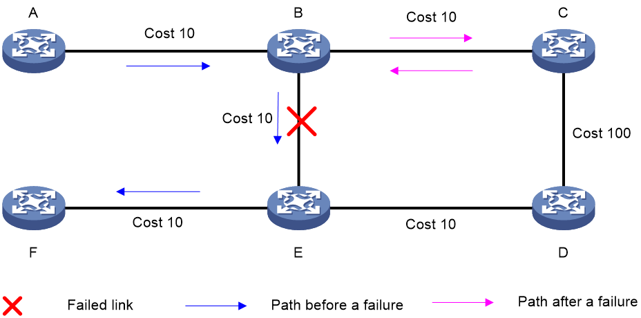
As shown in Figure 24, node A sends data packets to node F. When the link between node B and node E fails, node B forwards the data packets to node C. The cost of the link between node C and node D is 100 (which is greater than the cost of the link between node C and node D) and the routes on node C have not converged. As a result, node C determines that the next hop of the optimal path to reach node F is node B. Then, node C forwards the data packets back to node B, which causes a loop.
Figure 24 TI-LFA application scenario
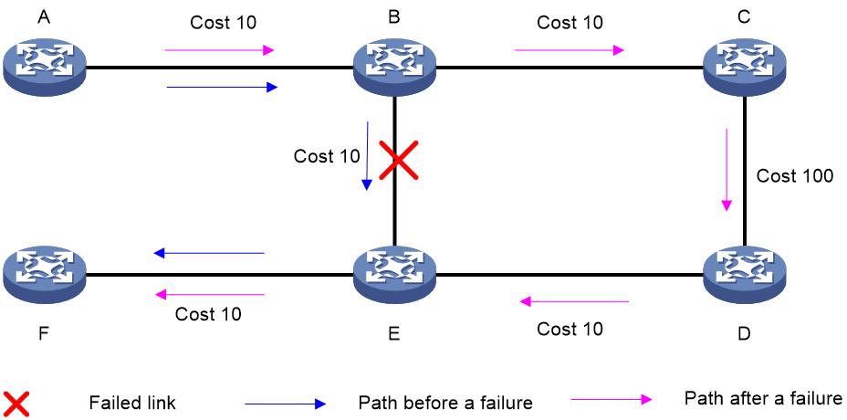
To resolve this issue, deploy TI-FLA on the SRv6 network. As shown in Figure 25, when the link between node B and node E fails, node B uses the backup path calculated by TI-LFA to forward the data packets along the B->C->D->E path.
Figure 25 TI-LFA forwarding network diagram
TI-LFA FRR concepts
TI-LFA FRR uses the concepts of RLFA FRR defined in RFC 7490:
· P space—A set of nodes reachable (using pre-convergence paths) from the PLR without using the protected link or node (including equal-cost path splits). Nodes in the P space are called P nodes.Calculation of P nodes typically involves building an SPF tree with the PLR as the root node, and then identifying nodes on the SPF tree that meet the loop-free requirement.
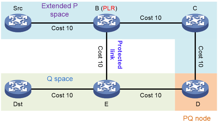
· Extended P space—A set of nodes reachable (using pre-convergence paths) from the neighbors of the PLR (except for the protected node) without using the protected link or node (including equal-cost path splits). The P space is a subset of the extended P space. Nodes in the extended P space are also called P nodes. Neighbor nodes of the PLR are N nodes. As shown in Figure 26, the expanded P space contains nodes Src, B, C, and D. The P nodes meet the following loop-free requirement: Distance (N, P) < Distance (N, PLR) + Distance (PLR, P).
· Q space—A set of nodes that can reach (using pre-convergence paths) the destination without using the protected link or node (including equal-cost path splits). Nodes in the Q space are called Q nodes.
TI-LFA FRR path calculation
As shown in Figure 27, PE 1 is the source node. P 1 is the faulty node. PE 2 is the destination node. The numbers on links represent the link costs. A data flow traverses PE 1, P 1, and PE 2. To protect data against P 1 failure, TI-LFA FRR calculates the extended P space, Q space, shortest path tree converged after P 1 fails, repair list, and backup output interface, and creates the backup forwarding entry.
TI-LFA FRR calculates the backup path by using the following steps:
1. Calculates the extended P space: P 2.
2. Calculates the Q space: PE 2 and P 4.
3. Calculates the shortest path tree converged after P 1 fails: PE 1 --> P 2 --> P 4 --> PE 2.
4. Calculates the repair list: End.X SID C of the link between P 2 and P 3 and End.X SID D of the link between P 3 and P 4.
5. Calculates the backup output interface, that is, the output interface to the next hop after the link from PE 1 to P 1 fails.
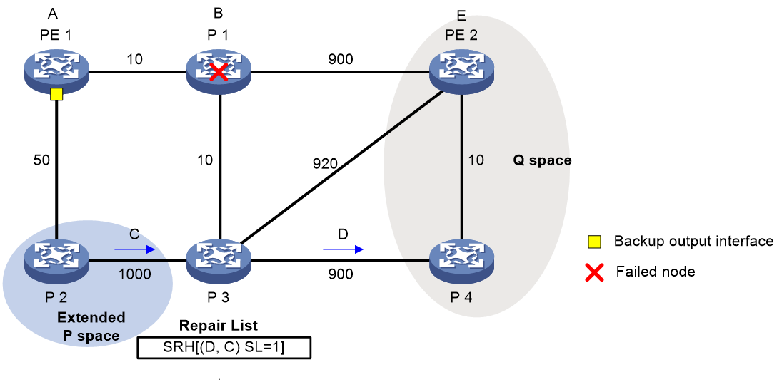
TI-LFA FRR forwarding process
After TI-LFA FRR finishes backup path calculation, traffic will be switched to the backup path in response to a primary path failure.
As shown in Figure 28, P 2 is a P node and P 4 and PE 2 are Q nodes. When the next hop on the primary path (P 1) fails, TI-LFA FRR switches the traffic to the backup path. The following are the detailed steps:
1. PE 1 looks up the IPv6 routing table for the destination IPv6 address of a packet and finds that the next hop is P 2. PE 1 encapsulates the packet according to the repair list.
¡ Adds an SRH header. The SID list is Segment List [0]=D and Segment List [1]=C. The SIDs are arranged from the farthest node to the nearest node.
¡ Adds an outer IPv6 header. The source address is address A on source node PE 1 and the destination address is the address pointed by SL. Because the SL is 1, the destination address is C as pointed by Segment List [1].
2. After P2 receives the packet, it performs the following operations:
a. Checks the SL value in the SRH header and decreases the value by 1.
b. Searches for the address pointed by Segment List [0] and finds that the address is End.X SID D between P 3 and P 4.
c. Replaces the destination address in the outer IPv6 header with End.X SID D.
d. Obtains the output interface and next hop according to End.X SID C and forwards the encapsulated packet to P 3.
3. After P3 receives the packet, it performs the following operations:
a. Checks the SL value in the SRH header and finds that the SL value is 0.
b. Decapsulates the packet.
c. Obtains the output interface and next hop according to End.X SID D and forwards the packet to P 4.
4. After P4 receives the packet, it searches the IP routing table for the destination IP address of the packet and forwards the packet to PE 2.
Figure 28 Data forwarding over the TI-LFA FRR backup path
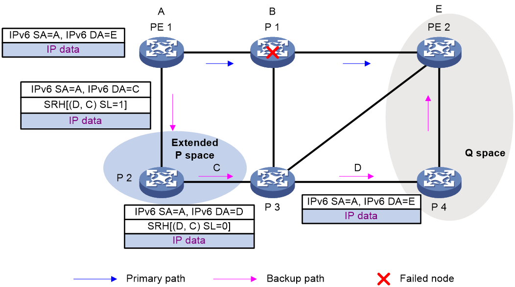
Microloop avoidance after a network failure
As shown in Figure 29, when Device B fails, traffic to Device C will be switched to the backup path calculated by TI-LFA. After Device A finishes route convergence, traffic will be switched to the post-convergence path. If Device D and Device F have not finished route convergence and still forward traffic along the pre-convergence path, a loop is formed between Device A and Device F. The loop exists until Device D and Device F finish route convergence.
FRR microloop avoidance and SR microloop avoidance can resolve this issue. After you configure TI-LFA, Device A first switches traffic to the backup path calculated by TI-LFA when Device B fails. Then, Device A waits for Device D and Device F to finish route convergence before starting route convergence. After Device A also finishes route convergence, Device A switches the traffic to the converged route.
Figure 29 Diagram for microloop avoidance after a network failure
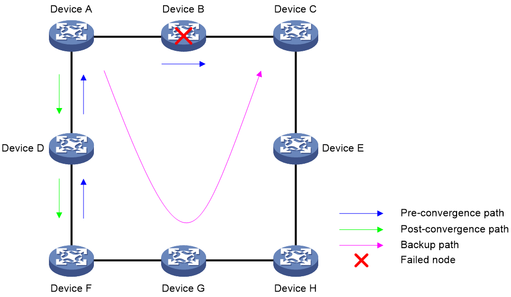
SR microloop avoidance after a failure recovery
As shown in Figure 30, before the link between Device B and Device C recovers, traffic traverses along the backup path. After the link recovers, Device A forwards the traffic to Device B if Device A finishes route convergence before Device B. With route convergence unfinished, Device B still forwards the traffic along the backup path. A loop is formed between Device A and Device B.
SR microloop avoidance can resolve this issue. After the link recovers, SR microloop avoidance automatically calculates the optimal path from Device A to Device C and forwards traffic along the path. To forward a packet along the newly calculated path, Device A adds, for example, the adjacency SID from Device B to Device C, to the packet and then sends the packet to Device B. Then, Device B forwards the packet to Device C based on the path information.
Upon expiration of the microloop avoidance RIB-update-delay timer and completion of route convergence on Device B, Device A does not add path information to packets anymore. It will forward packets to Device C as usual.
Figure 30 Diagram for SR microloop avoidance after a failure recovery
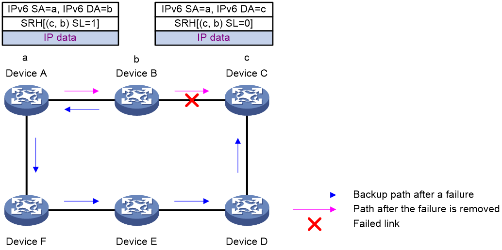
Protocols and standards
· draft-previdi-6man-segment-routing-header
· draft-ietf-6man-segment-routing-header
· draft-filsfils-spring-segment-routing
· draft-filsfils-spring-srv6-network-programming
Configuring SRv6
Restrictions and guidelines: SRv6 configuration
As a best practice, set the next hop address of the static route to the interface address of the CE device connected to the local PE when you configure inter-VPN static routing on PE devices for communication between different VPNs or between a VPN and the public network. This guidelines is applicable to SRv6 End.DT4/End.DT6/End.DT46 scenarios. Assume that the network topology is CE 1 (interface 1) - (interface 2) PE 1 (interface 3) - (interface 4) PE 2 (interface 5) - (interface 6) CE 2. For traffic from PE 1 to PE 2, you must specify the next hop as the IP address of interface 6 on CE 2 that is directly connected to PE 2 when you configure inter-VPN static routing on PE 2.
SRv6 tasks at a glance
To configure SRv6, perform the following tasks:
1. Configuring SRv6 SIDs
¡ Configuring non-compressible SRv6 SIDs
¡ This task is required if SRv6 compression is enabled.
2. (Optional.) Manage SRv6 SIDs
¡ Configuring dynamic End.X SID deletion delay
¡ Configuring the delay time to flush static End.X SIDs to the FIB
¡ Using IGP to advertise SRv6 SIDs
¡ Enabling BGP to advertise routes for a locator
¡ This task is required in an inter-AS network.
3. (Optional.) Configuring TI-LFA FRR
4. (Optional.) Configuring the SRv6 MTU
5. (Optional.) Configuring the SRv6 DiffServ mode
6. (Optional.) Enabling SNMP notifications for SRv6
Before you configure an SRv6 tunnel, perform the following tasks:
· Determine the ingress node, transit nodes, and egress node of the SRv6 tunnel.
· Plan the IPv6 address of each SR node.
Configuring non-compressible SRv6 SIDs
Configuring the local locator and opcode
Restrictions and guidelines
Each locator must have a unique name.
Do not configure the same IPv6 address prefix and prefix length for different locators. In addition, the IPv6 address prefixes of different locators cannot overlap.
You cannot disable SRv6 or delete a locator in SRv6 view if the locator has dynamic SRv6 SIDs that are being used.
You can change a common locator to a COC16 locator in next mode or default mode, and vice versa. When you do that, you do not need to delete the configured locator. You only need to re-configure the locator command and change the parameter settings as required.
· To change a common locator to a COC16 locator in next mode or default mode, re-configure the locator and specify the compress-16 and non-compress-static keywords. Other parameters are not editable.
· To change a COC16 locator in next mode or default mode to a common locator, re-configure the locator by using the locator command for a common locator without specifying the compress-16 and non-compress-static keywords. Other parameters are not editable.
You can change a COC-both locator to a common locator or vice versa without deleting the configured locator but directly editing the command parameters, as follows:
· Change a common locator to a COC-both locator by adding the common-prefix and non-compress-static parameters. Other parameters cannot be edited.
For example, assume you configure a common locator as locator test ipv6-prefix 100:1:: 80 static 8 args 8. You can change the locator to a COC-both locator by executing locator test ipv6-prefix 100:1:: 80 common-prefix 64 coc-both non-compress-static 8 static 8 args 8.
· Change a COC-both locator to a common locator by deleting the common-prefix and non-compress-static parameters. Other parameters cannot be edited.
For example, assume you configure a COC-both locator as locator test ipv6-prefix 100:1:: 80 common-prefix 64 coc-both non-compress-static 8 static 8 args 8. You can change the locator to a common locator by executing locator test ipv6-prefix 100:1:: 80 static 8 args 8.
Procedure
1. Enter system view.
system-view
2. Enable SRv6 and enter SRv6 view.
segment-routing ipv6
3. Configure a locator and enter SRv6 locator view.
locator locator-name [ ipv6-prefix ipv6-address prefix-length [ args args-length | static static-length ] * ]
4. (Optional.) Enable anycast for the locator.
anycast enable
By default, anycast is disabled for a locator.
A locator is an anycast locator if the A-bit is set in the Flags field of the Locator TLV in routing protocol packets. An anycast locator is shared by a group of SRv6 nodes.
5. Configure an opcode. Perform one of the following tasks:
¡ Configure an opcode for End SIDs.
opcode { opcode | hex hex-opcode } end { no-flavor | psp | psp-usp-usd | usp-usd }
¡ Configure an opcode for End.X SIDs.
opcode { opcode | hex hex-opcode } end-x interface interface-type interface-number [ member-port interface-type interface-number ] nexthop nexthop-ipv6-address { no-flavor | psp | psp-usp-usd | usp-usd } [ path-index index-value | weight weight-value ] *
For End.X, End.X(COC32), and End.X(COCNONE) SRv6 SIDs, if you specify a tunnel interface as the output interface, you can specify only tunnel interfaces in GRE over IPv4, IPsec over IPv4, or IPsec over IPv6 mode.
When you configure End.X SIDs, End.X(COC32) SIDs, or End.X(COCNONE) SIDs, you can use the path-index and weight keywords to specify different path indexes and load sharing weights for different output interfaces and nexthops for the same opcode. The End.X SIDs corresponding to the output interfaces are parallel SIDs. With this type of SIDs, traffic can be load shared among multiple output interfaces based on the specified weight.
¡ Configure an opcode for End.DT4 SIDs.
opcode { opcode | hex hex-opcode } end-dt4 [ vpn-instance vpn-instance-name [ evpn | l3vpn-evpn ] ]
The specified VPN instance must exist. The same End.DT4 SID cannot be configured in different VPN instances.
¡ Configure an opcode for End.DT6 SIDs.
opcode { opcode | hex hex-opcode } end-dt6 [ vpn-instance vpn-instance-name [ evpn | l3vpn-evpn ] ]
The specified VPN instance must exist. The same End.DT6 SID cannot be configured in different VPN instances.
¡ Configure an opcode for End.DT46 SIDs.
opcode { opcode | hex hex-opcode } end-dt46 [ vpn-instance vpn-instance-name [ evpn | l3vpn-evpn ] ]
The specified VPN instance must exist. The same End.DT46 SID cannot be configured in different VPN instances.
¡ Configure an opcode for End.DX4 SIDs.
opcode { opcode | hex hex-opcode } end-dx4 interface interface-type interface-number nexthop nexthop-ipv4-address [ vpn-instance vpn-instance-name [ evpn ] ]
The specified VPN instance must exist. The same End.DX4 SID cannot be configured with different output interfaces or next hops.
¡ Configure an opcode for End.DX6 SIDs.
opcode { opcode | hex hex-opcode } end-dx6 interface interface-type interface-number nexthop nexthop-ipv6-address [ vpn-instance vpn-instance-name [ evpn ] ]
The specified VPN instance must exist. The same End.DX6 SID cannot be configured with different output interfaces or next hops.
¡ Configure an opcode for End.DX2 SIDs.
opcode { opcode | hex hex-opcode } end-dx2 xconnect-group group-name connection connection-name
The specified cross-connect group and cross-connect must exist.
opcode { opcode | hex hex-opcode } end-dx2 vsi vsi-name interface interface-type interface-number service-instance instance-id
The specified VSI must exist.
¡ Configure an opcode for End.DX2L SIDs.
opcode { opcode | hex hex-opcode } end-dx2l xconnect-group group-name connection connection-name
The specified cross-connect group and cross-connect must exist.
opcode { opcode | hex hex-opcode } end-dx2l vsi vsi-name interface interface-type interface-number service-instance instance-id
The specified VSI must exist.
¡ Configure an opcode for End.DT2M SIDs.
opcode { opcode | hex hex-opcode } end-dt2m vsi vsi-name
The specified VSI must exist. The same End.DT2M SID cannot be configured in different VSIs.
¡ Configure an opcode for End.DT2U SIDs.
opcode { opcode | hex hex-opcode } end-dt2u vsi vsi-name
The specified VSI must exist. The same End.DT2U SID cannot be configured in different VSIs.
¡ Configure an opcode for End.DT2UL SIDs.
opcode { opcode | hex hex-opcode } end-dt2ul vsi vsi-name
The specified VSI must exist. The same End.DT2UL SID cannot be configured in different VSIs.
¡ Configure an opcode for End.OP SIDs.
opcode { opcode | hex hex-opcode } end-op
¡ Configure an opcode for End.M SIDs.
opcode { opcode | hex hex-opcode } end-m mirror-locator ipv6-address prefix-length
¡ Configure an opcode for End.DX2.AUTO SRv6 SIDs.
opcode { opcode | hex hex-opcode } end-dx2-auto interface ve-l2vpn { interface-number | interface-number.subnumber }
Configuring the remote locator
About this task
In the EVPN VPWS over SRv6 scenario, if the PEs cannot use BGP routes to establish SRv6 PWs, you need to establish a static SRv6 PW between the PEs to ensure correct packet forwarding. Because the PEs cannot transmit SRv6 SID information through BGP routes, you need to configure the SRv6 SIDs assigned by the local and remote ends to the cross-connect. To configure the SRv6 SID assigned by the local end, configure the opcode command for the associated locator. To configure the SRv6 SID assigned by the remote end, create the remote locator, and then use the peer command to specify the remote locator in static SRv6 configuration view of the cross-connect.
The remote locator setting on the local PE must be the same as the locator setting on the remote PE. The local and remote PEs must use consistent locator, remote locator, and SRv6 SID settings. For example:
· Configuration on the local PE (PE 1):
locator pe1 ipv6-prefix 100:: 64 static 32
opcode 1 end.dx2 xconnect-group pe1 connection pe1
remote-locator pe2 ipv6-prefix 200:: 64 static 32
xconnect-group pe1
connection pe1
static-srv6 local-service-id 1 remote-service-id 2
peer 2::2 end-dx2-sid remote-locator pe2 opcode 1
· Configuration on the remote PE (PE 2):
locator pe2 ipv6-prefix 200:: 64 static 32
opcode 1 end.dx2 xconnect-group pe2 connection pe2
remote-locator pe1 ipv6-prefix 100:: 64 static 32
xconnect-group pe2
connection pe2
static-srv6 local-service-id 1 remote-service-id 2
peer 1::1 end-dx2-sid remote-locator pe1 opcode 1
The locator for the local PE is 100::/64, and the remote locator is 200::/6. The locator for the remote PE is 200::/64, and the remote locator is 100::/6. The SRv6 SID assigned by the local PE to the cross-connect is End.DX2 SID 100::1. The SRv6 SID assigned by the remote PE to the cross-connect is End.DX2 SID 200::1.
When deploying an SRv6 PW in the EVPN VPWS over SRv6 scenario for packet forwarding, make sure the destination IPv6 address for packets is the SRv6 SID of the remote locator. Upon receiving the packets, the remote PE searches the local locator SID forwarding table, and perform one of the following operations:
· If a matching SRv6 SID is found in the local locator, the remote PE forwards the packets based on the SRv6 SID.
· If no matching SRv6 SID is found in the local locator, the remote PE discards the packets.
Restrictions and guidelines
When you create a remote locator, you must specify an IPv6 address prefix, prefix length, and static length for the remote locator. When you enter the view of an existing remote SRv6 locator, you only need to specify the remote locator name.
Each remote locator must have a unique name.
Do not specify the same IPv6 address prefix for different remote locators. In addition, the IPv6 address prefixes of different remote locators cannot overlap.
Do not specify the same IPv6 address prefix for the remote locator and local locator. In addition, the IPv6 address prefixes of the remote locator and local locator cannot overlap.
When you specify the compress-16 keyword, make sure the remote locator is a COC16 locator and is in corresponding mode.
Procedure
1. Enter system view.
system-view
2. Enable SRv6 and enter SRv6 view.
segment-routing ipv6
3. Configure a remote locator and enter remote SRv6 locator view. Perform one of the following tasks:
¡ Configure a common remote locator and enter remote SRv6 locator view.
remote-locator remote-locator-name [ ipv6-prefix ipv6-address prefix-length [ args args-length | static static-length ] * ]
¡ Configure a remote COC16 locator in default mode and enter remote SRv6 locator view.
remote-locator locator-name [ ipv6-prefix ipv6-address prefix-length compress-16 [ non-compress-static non-compress-static-length ] [ args args-length | static static-length ] * ]
¡ Configure a remote COC16 locator in next mode and enter remote SRv6 locator view.
remote-locator locator-name [ ipv6-prefix ipv6-address prefix-length compress-16 next [ non-compress-static non-compress-static-length ] [ args args-length | static static-length ] * ]
¡ Configure a remote COC16 locator in W-LIB mode and enter remote SRv6 locator view.
remote-locator locator-name [ ipv6-prefix ipv6-address prefix-length compress-16 next-wlib [ wlib-start wlib-start-value ] [ wlib-static-start wlib-static-value ] [ args args-length | static static-length ] * ]
Configuring G-SIDs
Configuring SRv6 SIDs on a COC32 locator
Restrictions and guidelines
The IPv6 prefix length must be longer than the common prefix length.
Procedure
1. Enter system view.
system-view
2. Enable SRv6 and enter SRv6 view.
segment-routing ipv6
3. Enable SRv6 compression.
srv6 compress enable
By default, SRv6 compression is disabled.
4. Configure a locator and enter SRv6 locator view.
locator locator-name [ ipv6-prefix ipv6-address prefix-length common-prefix common-prefix-length coc32 [ args args-length | static static-length ] * ]
5. Configure an opcode. Perform one of the following tasks:
¡ Configure an opcode for End SIDs.
opcode opcode end-coc32 { no-flavor | psp }
¡ Configure an opcode for End.X SIDs.
opcode opcode end-x-coc32 interface interface-type interface-number [ member-port interface-type interface-number ] nexthop nexthop-address { no-flavor | psp } [ path-index index-value | weight weight-value ] *
For End.X(COC32) SRv6 SIDs, if you specify a tunnel interface as the output interface, you can specify only tunnel interfaces in GRE over IPv4, IPsec over IPv4, or IPsec over IPv6 mode.
When you configure End.X SIDs, End.X(COC32) SIDs, or End.X(COCNONE) SIDs, you can use the path-index and weight keywords to specify different path indexes and load sharing weights for different output interfaces and nexthops for the same opcode. The End.X SIDs corresponding to the output interfaces are parallel SIDs. With this type of SIDs, traffic can be load shared among multiple output interfaces based on the specified weight.
¡ Configure an opcode for other segments. For more information, see "Configuring non-compressible SRv6 SIDs."
Configuring SRv6 SIDs on a COC-both locator
Restrictions and guidelines
For a COC-both locator that has both compressible and non-compressible SRv6 SIDs, you can set the same opcode for the compressible and non-compressible hybrid SRv6 SIDs.
You can change a COC-both locator to a COC16 locator in next mode or default mode, and vice versa. When you do that, you do not need to delete the configured locator. You only need to re-configure the locator and change the parameter settings as required.
· To change a COC-both locator to a COC16 locator in next mode or default mode, re-configure the locator by using the locator command for a COC16 locator in next mode or default mode and specify the compress-16 keyword. You can also edit the static-length argument. Other parameters are not editable.
· To change a COC16 locator in next mode or default mode to a COC-both locator, re-configure the locator by using the locator command for a COC-both locator without specifying the compress-16 keyword. You can also edit the static-length argument. Other parameters are not editable.
If a static opcode is configured in SRv6 locator view, you cannot change a COC16 locator to a locator of another type or vice versa.
You can change a COC-both locator to a common locator or vice versa without deleting the configured locator but directly editing the command parameters, as follows:
· Change a common locator to a COC-both locator by adding the common-prefix and non-compress-static parameters. Other parameters cannot be edited.
For example, assume you configure a common locator as locator test ipv6-prefix 100:1:: 80 static 8 args 8. You can change the locator to a COC-both locator by executing locator test ipv6-prefix 100:1:: 80 common-prefix 64 coc-both non-compress-static 8 static 8 args 8.
· Change a COC-both locator to a common locator by deleting the common-prefix and non-compress-static parameters. Other parameters cannot be edited.
For example, assume you configure a COC-both locator as locator test ipv6-prefix 100:1:: 80 common-prefix 64 coc-both non-compress-static 8 static 8 args 8. You can change the locator to a common locator by executing locator test ipv6-prefix 100:1:: 80 static 8 args 8.
Procedure
1. Enter system view.
system-view
2. Enable SRv6 and enter SRv6 view.
segment-routing ipv6
3. Enable SRv6 compression.
srv6 compress enable
By default, SRv6 compression is disabled.
4. Configure a locator and enter SRv6 locator view.
locator locator-name [ ipv6-prefix ipv6-address prefix-length common-prefix common-prefix-length coc-both [ non-compress-static non-compress-static-length ] [ args args-length | static static-length ] * ]
5. (Optional.) Reserve SRv6 SIDs.
reserved-sid-start sid-value count reserved-sid-count
By default, no SRv6 SIDs are reserved.
When the device generates an SRv6 TE policy based on received SRv6 TE policy routes, it must assign a BSID to the SRv6 TE policy. Use this command to reserve SRv6 SIDs that can be assigned to SRv6 TE policies as BSIDs. The reserved SRv6 SIDs cannot be used by other protocols.
6. Configure an opcode. Perform one of the following tasks:
¡ Configure an opcode for End (COCNONE) SIDs.
opcode { opcode | hex hex-opcode } end-coc-none { no-flavor | psp | psp-usp-usd | usp-usd }
End (COCNONE) SIDs are allocated from compressible SRv6 SID space. The SIDs have the same function as End SIDs.
¡ Configure an opcode for End.X (COCNONE) SIDs.
opcode { opcode | hex hex-opcode } end-x-coc-none interface interface-type interface-number [ member-port interface-type interface-number ] nexthop nexthop-ipv6-address { no-flavor | psp | psp-usp-usd | usp-usd } [ path-index index-value | weight weight-value ] *
End.X (COCNONE) SIDs are allocated from compressible SRv6 SID space. The SIDs have the same function as End.X SIDs.
For End.X(COCNONE) SRv6 SIDs, if you specify a tunnel interface as the output interface, you can specify only tunnel interfaces in GRE over IPv4, IPsec over IPv4, or IPsec over IPv6 mode.
When you configure End.X SIDs, End.X(COC32) SIDs, or End.X(COCNONE) SIDs, you can use the path-index and weight keywords to specify different path indexes and load sharing weights for different output interfaces and nexthops for the same opcode. The End.X SIDs corresponding to the output interfaces are parallel SIDs. With this type of SIDs, traffic can be load shared among multiple output interfaces based on the specified weight.
¡ Configure an opcode for other segments. For more information, see "Configuring non-compressible SRv6 SIDs."
Configuring SRv6 SIDs on a COC16 locator
About this task
A locator with the compress-16 keyword specified is a COC16 locator. This type of locator allocates SIDs in the 16-bit compression scenario. The following types of COC16 locators are available:
· Locator in default mode—A locator without the next keyword specified. It can allocate G-SIDs that carry the COC flavor, NEXT flavor, or COC & NEXT flavor, or common SIDs that do not carry COC or NEXT flavors. This type of locator is applicable to all 16-bit compression schemes.
· Locator in next mode—A locator with the next keyword specified. It can allocate G-SIDs that do not carry a COC flavor or carry only the NEXT flavor or common SIDs that do not carry a COC or NEXT flavor. When the device interoperates with a third-party device, you can configure locators in next mode to allocate SIDs if the third-party device supports only 16-bit compression with the move action.
· Locator in W-LIB mode—A locator with the next-wlib keyword specified. It can allocate G-SIDs that carry the NEXT flavor from the W-LIB or G-SIDs that carry the NEXT flavor from the compressed Function portion. SIDs for VPN services are allocated from the W-LIB in W-LIB mode locators.
Restrictions and guidelines
You can change a COC-both locator to a COC16 locator in next mode or default mode, and vice versa. When you do that, you do not need to delete the configured locator. You only need to re-configure the locator and change the parameter settings as required.
· To change a COC-both locator to a COC16 locator in next mode or default mode, re-configure the locator by using the locator command for a COC16 locator in next mode or default mode and specify the compress-16 keyword. You can also edit the static-length argument. Other parameters are not editable.
· To change a COC16 locator in next mode or default mode to a COC-both locator, re-configure the locator by using the locator command for a COC-both locator without specifying the compress-16 keyword. You can also edit the static-length argument. Other parameters are not editable.
If a static opcode is configured in SRv6 locator view, you cannot change a COC16 locator to a locator of another type or vice versa.
For a locator in W-LIB mode to allocate an opcode from the W-LIB, make sure the opcode or hex-opcode specified in the opcode command contains one of the values from wlib-static-value to wlib-start-value+7 in the locator command when you configure SIDs such as End.DT4 related to VPN services. Then, specify an opcode in the W-LIB. As a best practice, specify the hex-opcode argument to configure an opcode. For example, if the value for wlib-start-value is 0xFFF3 and the value for wlib-static-value is 0xFFF7, you must first specify a value between FFF7 and FFFA for hex-opcode, and then allocate the opcode in the W-LIB.
Configuring SRv6 SIDs on a locator in default mode
1. Enter system view.
system-view
2. Enable SRv6 and enter SRv6 view.
segment-routing ipv6
3. Enable SRv6 compression.
srv6 compress enable
By default, SRv6 compression is disabled.
4. Configure a locator and enter SRv6 locator view.
locator locator-name [ ipv6-prefix ipv6-address prefix-length compress-16 [ non-compress-static non-compress-static-length ] [ args args-length | static static-length ] * ]
5. Configure an opcode.
¡ Configure the device to allocate common SRv6 SIDs from the uncompressed Function portion. Common SRv6 SID do not carry COC and NEXT flavors.
For more information, see "Configuring non-compressible SRv6 SIDs."
¡ Configure the device to allocate SRv6 SIDs that carry COC or NEXT flavors from the compressed Function portion.
opcode { opcode | hex hex-opcode } end compress { coc | coc-next | next | psp-coc | psp-usd-next | usp-usd-coc-next }
The node behavior for the SIDs is End.
opcode { opcode | hex hex-opcode } end-x interface interface-type interface-number [ member-port interface-type interface-number ] nexthop nexthop-ipv6-address compress { coc | coc-next | next | psp-coc | psp-usd-next | psp-usp-usd-coc-next | usp-usd-coc-next }
The node behavior for the SIDs is End.X.
opcode { opcode | hex hex-opcode } end-dt4 [ vpn-instance vpn-instance-name [ evpn | l3vpn-evpn ] ] compress { next | coc-next }
The node behavior for the SIDs is End.DT4.
opcode { opcode | hex hex-opcode } end-dt46 [ vpn-instance vpn-instance-name [ evpn | l3vpn-evpn ] ] compress { next | coc-next }
The node behavior for the SIDs is End.DT46.
opcode { opcode | hex hex-opcode } end-dt6 [ vpn-instance vpn-instance-name [ evpn | l3vpn-evpn ] ] compress { next | coc-next }
The node behavior for the SIDs is End.DT6.
opcode { opcode | hex hex-opcode } end-dx4 interface interface-type interface-number nexthop nexthop-ipv4-address [ vpn-instance vpn-instance-name [ evpn ] ] compress { next | coc-next }
The node behavior for the SIDs is End.DX4.
opcode { opcode | hex hex-opcode } end-dx6 interface interface-type interface-number nexthop nexthop-ipv4-address [ vpn-instance vpn-instance-name [ evpn ] ] compress { next | coc-next }
The node behavior for the SIDs is End.DX6.
opcode { opcode | hex hex-opcode } end-dx2 xconnect-group group-name connection connection-name compress { next | coc-next }
The node behavior for the SIDs is End.DX2.
opcode { opcode | hex hex-opcode } end-dx2l xconnect-group group-name connection connection-name compress { next | coc-next }
The node behavior for the SIDs is End.DX2L.
opcode { opcode | hex hex-opcode } end-dx2l vsi vsi-name interface interface-type interface-number service-instance instance-id compress { next | coc-next }
The node behavior for the SIDs is End.DX2L.
opcode { opcode | hex hex-opcode } end-dt2m vsi vsi-name compress { next | coc-next }
The node behavior for the SIDs is End.DX2M.
opcode { opcode | hex hex-opcode } end-dt2u vsi vsi-name compress { next | coc-next }
The node behavior for the SIDs is End.DX2U.
opcode { opcode | hex hex-opcode } end-dt2ul vsi vsi-name compress { next | coc-next }
The node behavior for the SIDs is End.DX2UL.
¡ Configure the device to allocate SRv6 SIDs that do not carry COC flavors from the compressed Function portion.
opcode { opcode | hex hex-opcode } end-coc-none { no-flavor | psp | psp-usp-usd | usp-usd }
The node behavior for the SIDs is End.
opcode { opcode | hex hex-opcode } end-x-coc-none interface interface-type interface-number [ member-port interface-type interface-number ] nexthop nexthop-ipv6-address { no-flavor | psp | psp-usp-usd | usp-usd }
The node behavior for the SIDs is End.X.
Configuring SRv6 SIDs on a locator in next mode
1. Enter system view.
system-view
2. Enable SRv6 and enter SRv6 view.
segment-routing ipv6
3. Enable SRv6 compression.
srv6 compress enable
By default, SRv6 compression is disabled.
4. Configure a locator and enter SRv6 locator view.
locator locator-name [ ipv6-prefix ipv6-address prefix-length compress-16 next [ non-compress-static non-compress-static-length ] [ args args-length | static static-length ] * ]
5. Configure an opcode.
¡ Configure the device to allocate common SRv6 SIDs from the uncompressed Function portion. Common SRv6 SID do not carry COC and NEXT flavors. For more information, see "Configuring non-compressible SRv6 SIDs."
¡ Configure the device to allocate SRv6 SIDs that carry NEXT flavors from the compressed Function portion.
opcode { opcode | hex hex-opcode } end compress { next | psp-usd-next }
The node behavior for the SIDs is End.
opcode { opcode | hex hex-opcode } end-x interface interface-type interface-number [ member-port interface-type interface-number ] nexthop nexthop-ipv6-address compress { next | psp-usd-next }
The node behavior for the SIDs is End.X.
opcode { opcode | hex hex-opcode } end-dt4 [ vpn-instance vpn-instance-name [ evpn | l3vpn-evpn ] ] compress next
The node behavior for the SIDs is End.DT4.
opcode { opcode | hex hex-opcode } end-dt46 [ vpn-instance vpn-instance-name [ evpn | l3vpn-evpn ] ] compress next
The node behavior for the SIDs is End.DT46.
opcode { opcode | hex hex-opcode } end-dt6 [ vpn-instance vpn-instance-name [ evpn | l3vpn-evpn ] ] compress next
The node behavior for the SIDs is End.DT6.
opcode { opcode | hex hex-opcode } end-dx4 interface interface-type interface-number nexthop nexthop-ipv4-address [ vpn-instance vpn-instance-name [ evpn ] ] compress next
The node behavior for the SIDs is End.DX4.
opcode { opcode | hex hex-opcode } end-dx6 interface interface-type interface-number nexthop nexthop-ipv4-address [ vpn-instance vpn-instance-name [ evpn ] ] compress next
The node behavior for the SIDs is End.DX6.
opcode { opcode | hex hex-opcode } end-dx2 xconnect-group group-name connection connection-name compress next
The node behavior for the SIDs is End.DX2.
opcode { opcode | hex hex-opcode } end-dx2l xconnect-group group-name connection connection-name compress next
The node behavior for the SIDs is End.DX2L.
opcode { opcode | hex hex-opcode } end-dx2l vsi vsi-name interface interface-type interface-number service-instance instance-id compress next
The node behavior for the SIDs is End.DX2L.
opcode { opcode | hex hex-opcode } end-dt2m vsi vsi-name compress next
The node behavior for the SIDs is End.DX2M.
opcode { opcode | hex hex-opcode } end-dt2u vsi vsi-name compress next
The node behavior for the SIDs is End.DX2U.
opcode { opcode | hex hex-opcode } end-dt2ul vsi vsi-name compress next
The node behavior for the SIDs is End.DX2UL.
¡ Configure the device to allocate SRv6 SIDs that do not carry COC flavors from the compressed Function portion.
opcode { opcode | hex hex-opcode } end-coc-none { no-flavor | psp | psp-usp-usd | usp-usd }
The node behavior for the SIDs is End.
opcode { opcode | hex hex-opcode } end-x-coc-none interface interface-type interface-number [ member-port interface-type interface-number ] nexthop nexthop-ipv6-address { no-flavor | psp | psp-usp-usd | usp-usd }
The node behavior for the SIDs is End.X.
Configuring SRv6 SIDs on a locator in W-LIB mode
1. Enter system view.
system-view
2. Enable SRv6 and enter SRv6 view.
segment-routing ipv6
3. Enable SRv6 compression.
srv6 compress enable
By default, SRv6 compression is disabled.
4. Configure a locator and enter SRv6 locator view.
locator locator-name [ ipv6-prefix ipv6-address prefix-length compress-16 next-wlib [ wlib-start wlib-start-value ] [ wlib-static-start wlib-static-value ] [ args args-length | static static-length ] * ]
5. Configure an opcode.
¡ Configure the device to allocate SRv6 SIDs that carry the NEXT flavor from the W-LIB in the locator.
opcode { opcode | hex hex-opcode } end-dt4 [ vpn-instance vpn-instance-name [ evpn | l3vpn-evpn ] ] compress next
The node behavior for the SIDs is End.DT4.
opcode { opcode | hex hex-opcode } end-dt46 [ vpn-instance vpn-instance-name [ evpn | l3vpn-evpn ] ] compress next
The node behavior for the SIDs is End.DT46.
opcode { opcode | hex hex-opcode } end-dt6 [ vpn-instance vpn-instance-name [ evpn | l3vpn-evpn ] ] compress next
The node behavior for the SIDs is End.DT6.
opcode { opcode | hex hex-opcode } end-dx4 interface interface-type interface-number nexthop nexthop-ipv4-address [ vpn-instance vpn-instance-name [ evpn ] ] compress next
The node behavior for the SIDs is End.DX4.
opcode { opcode | hex hex-opcode } end-dx6 interface interface-type interface-number nexthop nexthop-ipv4-address [ vpn-instance vpn-instance-name [ evpn ] ] compress next
The node behavior for the SIDs is End.DX6.
opcode { opcode | hex hex-opcode } end-dx2 xconnect-group group-name connection connection-name compress next
The node behavior for the SIDs is End.DX2.
opcode { opcode | hex hex-opcode } end-dx2l xconnect-group group-name connection connection-name compress next
The node behavior for the SIDs is End.DX2L.
opcode { opcode | hex hex-opcode } end-dx2l vsi vsi-name interface interface-type interface-number service-instance instance-id compress next
The node behavior for the SIDs is End.DX2L.
opcode { opcode | hex hex-opcode } end-dt2m vsi vsi-name compress next
The node behavior for the SIDs is End.DX2M.
opcode { opcode | hex hex-opcode } end-dt2u vsi vsi-name compress next
The node behavior for the SIDs is End.DX2U.
opcode { opcode | hex hex-opcode } end-dt2ul vsi vsi-name compress next
The node behavior for the SIDs is End.DX2UL.
¡ Configure the device to allocate SRv6 SIDs that do not carry COC flavors from the compressed Function portion.
opcode { opcode | hex hex-opcode } end compress { next | psp-usd-next }
The node behavior for the SIDs is End.
opcode { opcode | hex hex-opcode } end-x interface interface-type interface-number [ member-port interface-type interface-number ] nexthop nexthop-ipv6-address compress { next | psp-usd-next }
The node behavior for the SIDs is End.X.
opcode { opcode | hex hex-opcode } end-coc-none { no-flavor | psp | psp-usp-usd | usp-usd }
The node behavior for the SIDs is End.
opcode { opcode | hex hex-opcode } end-x-coc-none interface interface-type interface-number [ member-port interface-type interface-number ] nexthop nexthop-ipv6-address { no-flavor | psp | psp-usp-usd | usp-usd }
The node behavior for the SIDs is End.X.
Configuring the length of the GIB
About this task
Perform this task to configure the length of the GIB. For example, if you set the GIB length to 8, the LIB length will be 16-8=8. Both the GIB and LIB have eight values. When you use the locator command to configure a COC16 locator, the value range for the highest 4 bits of the Node ID is 0x0 to 0x7 (0000 to 0111). The value range for the highest 4 bits of the compression Function portion is 0x8 to 0xF (1000 to 1111).
Restrictions and guidelines
Make sure the GIB is consistent across all network devices, including devices that use the non-compression schemes.
You cannot change the length of the GIB after you configure a COC16 locator. To change the length of the GIB, you must first delete the COC16 locator.
Procedure
1. Enter system view.
system-view
2. Enter SRv6 view.
segment-routing ipv6
3. Configure the length of the GIB.
csid-proportion global-id-block gib-proportion-value
By default, the length of the GIB is 14.
Configuring dynamic End.X SID deletion delay
About this task
Packet loss occurs between OSPFv3 or IS-IS neighbors if the neighbors frequently delete and request dynamically allocated End.X SIDs for the links between them because of neighbor flapping. To resolve this issue, set a delay timer for deleting dynamically allocated End.X SIDs when the neighbors are disconnected. If the neighbors are still disconnected when the delay timer expires, the device deletes the dynamically allocated End.X SIDs.
Restrictions and guidelines
The device always immediately deletes automatically allocated End.X SIDs without any delay in the following situations:
· The reset ospfv3 process command is executed. For more information about this command, see OSPFv3 commands in Layer 3—IP Routing Command Reference.
· The reset isis all command is executed. For more information about this command, see IS-IS commands in Layer 3—IP Routing Command Reference.
· Interfaces are deleted or removed. For example, an interface module is removed, or a subinterface or VLAN interface is deleted.
Procedure
1. Enter system view.
system-view
2. Enter IS-IS IPv6 address family view or OSPFv3 process view.
¡ Execute the following commands in sequence to enter IS-IS IPv6 address family view:
isis [ process-id ] [ vpn-instance vpn-instance-name ]
address-family ipv6 [ unicast ]
¡ Enter OSPFv3 process view.
ospfv3 [ process-id | vpn-instance vpn-instance-name ] *
3. Enable dynamic End.X SID deletion delay and set the delay time.
segment-routing ipv6 end-x delete-delay [ time-value ]
By default, dynamic End.X SID deletion delay is enabled and the delay time is 1800 seconds.
Configuring the delay time to flush static End.X SIDs to the FIB
About this task
When a neighbor fails, the interface connected to that neighbor goes down. The End.X SID associated with the interface cannot take effect. When the neighbor recovers, the interface also comes up and the static End.X SID associated with the interface takes effect. Because route convergence has not finished, the local device cannot forward packets according to the route entry of the static End.X SID. As a result, packet forwarding failure or packet loss occurs. (Dynamic End.X SIDs do not have this issue, because they are flushed to the FIB after route convergence is completed.) To avoid this issue, perform this task to delay flushing the static End.X SID associated with the interface to the FIB. During the delay time, the local device does not forward traffic through the link attached to the interface. The delay configuration avoids packet loss within the delay time.
Procedure
1. Enter system view.
system-view
2. Enable SRv6 and enter SRv6 view.
segment-routing ipv6
3. Configure the delay time to flush static End.X SIDs to the FIB
end-x update-delay delay-time
By default, static End.X SIDs are not delayed to flush to the FIB.
Using IGP to advertise SRv6 SIDs
About this task
Use an IGP protocol to advertise a locator and the SRv6 SIDs of that locator by applying the locator to the IGP protocol.
To use an IGP protocol to advertise G-SIDs to neighbors, enable SRv6 compression for that IGP protocol.
Prerequisites
If IS-IS is used to advertise SRv6 SIDs, make sure the cost style of IS-IS is wide, compatible, or wide-compatible. For more information about the cost styles of IS-IS, see Layer 3—IP Routing Configuration Guide.
Using IS-IS to advertise SRv6 SIDs
1. Enter system view.
system-view
2. Enter IS-IS process view.
isis [ process-id ] [ vpn-instance vpn-instance-name ]
3. Enter IS-IS IPv6 address family view.
address-family ipv6 [ unicast ]
4. Apply a locator to IS-IS IPv6 address family.
segment-routing ipv6 locator locator-name [ level-1 | level-2 ] [ auto-sid-coc32 [ additive ] | auto-sid-coc-both { all | coc32 | coc32-all | coc32-none } | auto-sid-disable ] [ member-port-enable ] [ cost cost-value ] [ tag tag-value ] [ track track-entry-number { adjust-cost cost-offset | suppression } ]
By default, no locators are applied to IS-IS IPv6 address family.
Repeat this command to apply multiple locators to IS-IS IPv6 address family for the family to advertise multiple SRv6 SIDs.
If the neighbor interface is a Layer 3 aggregate interface, you can specify the member-port-enable keyword to enable SRv6 SID allocation to the member ports of the Layer 3 aggregate interface.
When multiple SRv6 nodes act as service gateways and form a VRRP group to ensure service reliability, these SRv6 nodes can advertise the same anycast locator. To differentiate the locators advertised by the master and backup service gateways and to ensure that SRv6 traffic is prioritized to the master service gateway in the VRRP group, you can specify the track track-entry-number parameter. This parameter specifies the track entry to be associated with the VRRP group when IS-IS advertises locators.
After you associate a track entry with a VRRP group, the track module monitors the state of the nodes in the VRRP group. When an SRv6 node in the VRRP group transitions to Backup or Initialize state, the Track module sets the track entry to Negative state. When the SRv6 node advertises a locator through IS-IS, the SRv6 node adds the interface cost adjustment value to the cost or suppresses advertisement of the locator. When the SRv6 node in the VRRP group transitions to Master or Inactive state or if the VRRP group does not exist, the cost and advertisement of the locator is not affected.
5. Enable SRv6 compression for IPv6 IS-IS.
srv6 compress enable [ level-1 | level-2 ]
By default, SRv6 compression is disabled for IPv6 IS-IS.
Use this command only when IPv6 IS-IS is used to advertise G-SIDs.
6. (Optional.) Specify an aggregate route for a locator.
summary ipv6-prefix prefix-length algorithm algo-id [ explicit ]
By default, no aggregate route is specified for a locator.
To aggregate routes from a locator, you must first associate the routes with a Flex-Algo algorithm by using the flex-algo algorithm command. Then, the size of the local LSDB and the LSPs generated by the local router can be reduced. For more information about route aggregation and Flex-Algo algorithms, see IS-IS configuration in Layer 3—IP Routing Configuration Guide.
7. (Optional.) Configure the administrative tag value for SRv6 locators.
segment-routing ipv6 admin-tag tag-value
By default, SRv6 locators do not carry an administrative tag value when they are advertised by IS-IS.
To import only specific SRv6 locators when the device imports IS-IS routes from different levels and areas or learns IS-IS routes from IS-IS neighbors, use this command to configure the administrative tag value for SRv6 locators. Then use the if-match tag command to filter SRv6 locators with different administrative tags.
Using OSPFv3 to advertise SRv6 SIDs
1. Enter system view.
system-view
2. Enter OSPFv3 process view.
ospfv3 [ process-id | vpn-instance vpn-instance-name ] *
3. Apply a locator to the OSPFv3 process.
segment-routing ipv6 locator locator-name[ auto-sid-coc32 [ additive ] | auto-sid-coc-both { all | coc32 | coc32-all | coc32-none } | auto-sid-disable ]
By default, no locators are applied to an OSPFv3 process.
Repeat this command to apply multiple locators to the OSPFv3 process for the process to advertise multiple SRv6 SIDs.
4. Enable SRv6 compression for OSPFv3.
srv6 compress enable
By default, SRv6 compression is disabled for OSPFv3.
Use this command only when OSPFv3 is used to advertise G-SIDs.
5. (Optional.) Specify a type value for an SRv6 SID sub-TLV included in OSPFv3 routes.
segment-routing ipv6 sid-sub-tlv-type { end-x end-x-value | lan-end-x lan-end-x-value }
By default, the type value is 31 for the P2P End.X SID sub-TLV included in OSPFv3 routes and 32 for the LAN End.X SID sub-TLV included in OSPFv3 routes.
The type values for the End.X SID sub-TLVs included in OSPFv3 routes might vary by device model. For device intercommunication, use this command to ensure that all devices have the same type value for the same End.X SID sub-TLV included in OSPFv3 routes.
By default, the type value is 11 for both the P2P End.X SID sub-TLV and ASLA sub-TLV. To avoid conflict, you must use this command to change the type value of the P2P End.X SID sub-TLV.
6. (Optional.) Configure the TLVs and flag bits in the OSPFv3 extensions for SRv6 to be compatible with the private protocol.
segment-routing ipv6 private-srv6-extensions compatible
By default, the SRv6 Capabilities TLV type values, Sub TLV type values, and flag bits in OSPFv3 packets follow the definitions in draft-ietf-lsr-ospfv3-srv6-extensions-09. For a successful advertisement of SRv6 locators and SRv6 SIDs, make sure OSPFv3 neighbors follow the same standard.
If you configure both the segment-routing ipv6 sid-sub-tlv-type and segment-routing ipv6 private-srv6-extensions compatible commands, the End.X SID Sub-TLV Type and LAN End.X SID Sub-TLV Type values specified in the segment-routing ipv6 sid-sub-tlv-type command take precedence.
7. (Optional.) Enable compatibility of the Locator field in SRv6 Locator TLVs with earlier drafts.
segment-routing ipv6 compatible locator-fixed-length
By default, the Locator field in SRv6 locator LSAs is of variable length, with a maximum of 128 bytes.
The length of the Locator field in SRv6 Locator TLVs is defined as variable in draft-ietf-lsr-ospfv3-srv6-extensions-12 and later drafts and can be up to 128 bits. The length of the Locator field can vary based on the configured locator segment length. However, the length is fixed at 128 bits in draft-ietf-lsr-ospfv3-srv6-extensions-11 and earlier drafts.
Enabling BGP to advertise routes for a locator
About this task
Perform this task in an inter-AS BGP network. This task enables the device to generate routes for a locator in the BGP IPv6 unicast routing table and use BGP to advertise the routes to BGP peers.
By collaborating with Track, BGP can adjust the priority of the advertised locators based on the status returned by Track. This enables the device to respond quickly to changes in the features associated with the track entry, preventing traffic loss caused by link or VRRP failures.
After you specify the track track-entry-number parameter, BGP binds the generated routes for the locator to the track entry.
· When the track entry is in Negative state, BGP changes the priority of the generated routers for the locator to the lowest level (by setting the MED value to the maximum and the local preference to the minimum).
· When the track entry is in Positive state, BGP restores the MED value and local preference of the routes for the locator to their original levels from when the routes were generated.
Restrictions and guidelines
For the command to be executed successfully, make sure the specified track entry already exists before you execute the advertise srv6 locator command if you have specifies the track track-entry-number parameter in the command.
Procedure
1. Enter system view.
system-view
2. Enter BGP instance view.
bgp as-number [ instance instance-name ]
3. Enter BGP IPv6 unicast address family view.
address-family ipv6 [ unicast ]
4. Configure the device to generate routes for the specified locator in the BGP IPv6 unicast routing table and advertise the routes to BGP peers.
advertise srv6 locator locator-name [ route-policy route-policy-name ] [ track track-entry-number ]
By default, the device does not generate routes for a locator in the BGP IPv6 unicast routing table.
Configuring BGP-EPE
Enabling SRv6 BGP-EPE
About this task
BGP-EPE allocates BGP peer SIDs to inter-AS segments. The device advertises the peer SIDs to a network controller through BGP LS messages. The controller orchestrates the IGP SIDs and BGP peer SIDs to realize optimal inter-AS traffic forwarding.
With this feature, the device can allocate SRv6 SIDs to its connected BGP peers or peer groups to identify its connected BGP peers or links.
With a locator specified, this feature enables the device to dynamically allocate PeerNode SIDs and PeerAdj SIDs to peers. With the static-sid keyword specified, this feature enables you to manually specify the flavors for PeerNode SIDs and PeerAdj SIDs and the allocation method.
Restrictions and guidelines
If you do not specify any parameters for the peer egress-engineering srv6 command, the device will dynamically allocate SRv6 SIDs to peers. The SRv6 SIDs belong to the locator specified by using the segment-routing ipv6 egress-engineering locator command in BGP instance view.
When you use the peer egress-engineering srv6 command for a peer, follow these restrictions and guidelines:
· If you use this command to specify multiple locators for that peer, only the most recent configuration takes effect.
· If you use this command to specify multiple static SRv6 SIDs:
¡ For the same type of locator, the most recent configuration takes effect.
¡ For different types of locators, multiple types of SRv6 SIDs can be allocated.
¡ If the coc32 keyword and the coc-both coc32 keyword are specified multiple times, the most recent configuration takes effect.
If you specify a static SRv6 SID for a peer, the specified static SRv6 SID must belong to the locator specified by using the segment-routing ipv6 egress-engineering locator command in BGP instance view. To identify whether the static SRv6 SID takes effect, use the display bgp egress-engineering ipv6 command. If the static SRv6 SID does not take effect, the static SRv6 SID has been used by other protocols. Before the static SRv6 SID is released, BGP-EPE does not dynamically allocate an SRv6 SID. After the static SRv6 SID is released, first use the undo peer egress-engineering srv6 command to remove the original static SRv6 SID configuration. Then, use the peer egress-engineering srv6 command to reconfigure the static SRv6 SID.
The static SRv6 SIDs specified by using the following commands cannot be the same:
· peer egress-engineering srv6.
· egress-engineering srv6 peer-set.
The auto-sid-coc32 and coc32 keywords take effect only when the locator applied to BGP-EPE is a COC32 locator.
The auto-sid-coc-both and coc-both keywords take effect only when the locator applied to BGP-EPE is a COC-both locator.
The coc, coc-next, coc-none, next, psp-coc, psp-usd-next, and psp-usp-usd-coc-next keywords take effect only when the locator applied to BGP-EPE is a COC16 locator.
Procedure
1. Enter system view.
system-view
2. Enter BGP instance view.
bgp as-number [ instance instance-name ]
3. Enable SRv6 BGP-EPE. Perform one of the following tasks:
¡ Common locators:
peer group-name egress-engineering srv6
peer ipv6-address prefix-length egress-engineering srv6 [ locator locator-name ]
peer ipv6-address egress-engineering srv6 static-sid { psp psp-sid | no-psp-usp no-psp-usp-sid } *
peer ipv6-address egress-engineering srv6 static-sid { no-flavor no-flavor-sid | psp psp-sid | psp-usp-usd psp-usp-usd-sid | usp-usd usp-usd-sid } *
¡ Locators with the no-psp-usp keyword in the 32-bit G-SRv6 compression scenario:
peer ipv6-address egress-engineering srv6 [ locator locator-name [ auto-sid-coc32 [ additive ] | auto-sid-coc-both { all | coc32 | coc32-all | coc32-none } ] | static-sid [ coc32 | coc-both { coc32 | coc32-none } ] { psp psp-sid | no-psp-usp no-psp-usp-sid } * ]
undo peer ipv6-address egress-engineering srv6 [ locator | static-sid { psp | no-psp-usp } * ]
¡ Locators with the no-flavor keyword in the 32-bit G-SRv6 compression scenario:
peer ipv6-address egress-engineering srv6 [ locator locator-name [ auto-sid-coc32 [ additive ] | auto-sid-coc-both { all | coc32 | coc32-all | coc32-none } ] | static-sid { coc32 | coc-both coc32 } { no-flavor no-flavor-sid | psp psp-sid } * ]
peer ipv6-address egress-engineering srv6 [ locator locator-name [ auto-sid-coc32 [ additive ] | auto-sid-coc-both { all | coc32 | coc32-all | coc32-none } ] | static-sid [ coc-both coc32-none ] { no-flavor no-flavor-sid | psp psp-sid | psp-usp–usd psp-usp-usd-sid | usp–usd usp-usd-sid } * ]
undo peer ipv6-address egress-engineering srv6 [ locator | static-sid { no-flavor | psp | psp-usp–usd | usp–usd } * ]
¡ Locators in the 16-bit G-SRv6 compression scenario:
peer ipv6-address egress-engineering srv6 static-sid { no-flavor no-flavor-sid | psp psp-sid | psp-usp-usd psp-usp-usd-sid | usp-usd usp-usd-sid } *
peer ipv6-address egress-engineering srv6 static-sid coc-none { no-flavor coc-none-no-flavor-sid | psp coc-none-psp-sid | psp-usp-usd coc-none-psp-usp-usd-sid | usp-usd coc-none-usp-usd-sid } *
peer ipv6-address egress-engineering srv6 static-sid compress { coc coc-sid | coc-next coc-next-sid | next next-sid | psp-coc psp-coc-sid | psp-usd-next psp-usd-next-sid | psp-usp-usd-coc-next psp-usp-usd-coc-next-sid } *
undo peer ipv6-address egress-engineering srv6 static-sid { no-flavor | psp | psp-usp-usd | usp-usd } *
undo peer ipv6-address egress-engineering srv6 static-sid compress { coc | coc-next | next | psp-coc | psp-usd-next | psp-usp-usd-coc-next } *
By default, SRv6 BGP-EPE is disabled.
Applying a locator to BGP-EPE
About this task
Perform this task to restrict the range of End.X SIDs that can be allocated to BGP-EPE SRv6 peer sets and BGP-EPE-enabled peers in a BGP instance. All static SRv6 SIDs configured for the BGP-EPE SRv6 peer sets and peers must belong to the locator specified by performing this task.
Restrictions and guidelines
To dynamically allocate End.X SIDs from the specified locator:
· Do not configure a static SRv6 SID when you create a BGP-EPE SRv6 peer set by using the egress-engineering srv6 peer-set command.
· Do not specify a locator or configure a static SRv6 SID when you enable SRv6 BGP-EPE for a peer by using the peer egress-engineering srv6 command.
The auto-sid-coc32 keyword takes effect only when the specified locator is a COC32 locator.
The auto-sid-coc-both keyword takes effect only when the specified locator is a COC-both locator.
Without any parameters specified in the segment-routing ipv6 egress-engineering locator command, the system takes the following actions:
· If static SRv6 SIDs are configured, the system preferentially uses static SRv6 SIDs.
· If no static SRv6 SIDs are configured, the system dynamically allocates SRv6 SIDs.
· If the static SRv6 SIDs configured on a locator are End.X SIDs that have the same opcode value but different output interfaces and nexthops, BGP-EPE will not use the static SRv6 SIDs. Instead, it dynamically assigns SRv6 SIDs.
If the applied locator is a COC-16 locator, BGP might allocate SIDs in the following ways:
· Allocates SIDs based on the flavors carried by the static SIDs specified by the static-sid keyword in the peer egress-engineering srv6 and egress-engineering srv6 peer-set commands.
· If no static-sid keyword is specified in the peer egress-engineering srv6 and egress-engineering srv6 peer-set commands, BGP cannot dynamically allocate SIDs.
To display the allocated SIDs and the flavors that they carry, execute the display bgp egress-engineering ipv6 or display bgp egress-engineering srv6 peer-set command.
Procedure
1. Enter system view.
system-view
2. Enter BGP instance view.
bgp as-number [ instance instance-name ]
3. Apply a locator to BGP-EPE.
segment-routing ipv6 egress-engineering locator locator-name [ auto-sid-coc-both { all | coc32 | coc32-all | coc32-none } | auto-sid-coc32 [ additive ] | auto-sid-disable ]
By default, no locator is applied to BGP-EPE.
Configuring a BGP-EPE SRv6 peer set
About this task
If the device establishes BGP peer relationship with multiple devices, perform this task to add the peer devices to a peer set and allocate a PeerSet SID to the peer set. When the device forwards traffic based on the PeerSet SID, it distributes the traffic among the peers for load sharing.
With this feature and the segment-routing ipv6 egress-engineering locator command, you can allocate PeerSet SIDs to a group of BGP peers. By specifying the static-sid keyword, you can manually specify flavors carried by PeerSet SIDs and the allocation method for BGP peers. If you do not specify the static-sid keyword, you can allocate static PeerSet SIDs to a group of BGP peers. For a COC16 locator, you can only specify the static-sid keyword to allocate static PeerSet SIDs to a group of BGP peers.
Prerequisites
Enable SRv6 BGP-EPE on all peers that will be added to the BGP-EPE SRv6 peer set.
Use the segment-routing ipv6 egress-engineering locator command in BGP instance view to apply a locator to BGP-EPE.
· If automatic SID allocation is used, the device dynamically allocates an SRv6 SID to the BGP-EPE SRv6 peer set from the specified locator.
· If you specify a static SRv6 SID for the BGP-EPE SRv6 peer set, the specified static SRv6 SID must belong to the specified locator.
If you execute the egress-engineering srv6 peer-set command to specify multiple SRv6 SIDs for one peer set, the effective configuration is as follows:
· If the static-sid keyword is not specified, the most recent configuration takes effect.
· If the static-sid keyword is specified:
¡ For the same type of locators, the most recent configuration takes effect.
¡ For different types of locators, multiple SRv6 SIDs of different types can be allocated.
¡ If the coc32 keyword and the coc-both coc32 keyword are specified multiple times, only the most recent configuration takes effect.
The static SRv6 SIDs configured by using the following commands cannot be the same:
· egress-engineering srv6 peer-set.
· peer egress-engineering srv6.
The auto-sid-coc32 and coc32 keywords take effect only when the locator applied to BGP-EPE is a COC32 locator.
The auto-sid-coc-both and coc-both keywords take effect only when the locator applied to BGP-EPE is a COC-both locator.
For a COC32 locator or COC-both locator, if you do not specify the auto-sid-coc32 or auto-sid-coc-both keyword, the device dynamically allocates common SRv6 SIDs.
The coc, coc-next, coc-none, next, psp-coc, psp-usd-next, and psp-usp-usd-coc-next keywords take effect only when the locator applied to BGP-EPE is a COC16 locator.
Restrictions and guidelines
For a COC32 locator or COC-both locator, you can use both the segment-routing ipv6 egress-engineering locator and egress-engineering srv6 peer-set commands to dynamically allocate SRv6 SIDs by specifying the auto-sid-coc32, auto-sid-coc-both coc32, auto-sid-coc-both coc32-none keywords. If the two commands have inconsistent keyword settings, the keywords specified in the segment-routing ipv6 egress-engineering locator command take effect.
Procedure
1. Enter system view.
system-view
2. Enter BGP instance view.
bgp as-number [ instance instance-name ]
3. Create a BGP-EPE SRv6 peer set. Perform one of the following tasks:
¡ Common locators:
egress-engineering srv6 peer-set peer-set-name [ static-sid { psp psp-sid | no-psp-usp no-psp-usp-sid } * ]
egress-engineering srv6 peer-set peer-set-name [ static-sid { no-flavor no-flavor-sid | psp psp-sid | psp-usp–usd psp-usp-usd-sid | usp–usd usp-usd-sid } * ]
¡ Locators with the no-psp-usp keyword in the 32-bit G-SRv6 compression scenario:
egress-engineering srv6 peer-set peer-set-name [ auto-sid-coc32 [ additive ] | auto-sid-coc-both { all | coc32 | coc32-all | coc32-none } | static-sid [ coc32 | coc-both { coc32 | coc32-none } ] { psp psp-sid | no-psp-usp no-psp-usp-sid } * ]
¡ Locators with the no-flavor keyword in the 32-bit G-SRv6 compression scenario:
egress-engineering srv6 peer-set peer-set-name [ auto-sid-coc-both { all | coc32 | coc32-all | coc32-none } | auto-sid-coc32 [ additive ] | static-sid [ coc32 | coc-both coc32 ] { no-flavor no-flavor-sid | psp psp-sid } * ]
egress-engineering srv6 peer-set peer-set-name [ auto-sid-coc-both { all | coc32 | coc32-all | coc32-none } | auto-sid-coc32 [ additive ] | static-sid [ coc-both coc32-none ] { no-flavor no-flavor-sid | psp psp-sid | psp-usp–usd psp-usp-usd-sid | usp–usd usp-usd-sid } * ]
¡ Locators in the 16-bit G-SRv6 compression scenario:
egress-engineering srv6 peer-set peer-set-name static-sid { no-flavor no-flavor-sid | psp psp-sid | psp-usp-usd psp-usp-usd-sid | usp-usd usp-usd-sid } *
egress-engineering srv6 peer-set peer-set-name static-sid coc-none { no-flavor coc-none-no-flavor-sid | psp coc-none-psp-sid | psp-usp-usd coc-none-psp-usp-usd-sid | usp-usd coc-none-usp-usd-sid } *
egress-engineering srv6 peer-set peer-set-name static-sid compress { coc coc-sid | coc-next coc-next-sid | next next-sid | psp-coc psp-coc-sid | psp-usd-next psp-usd-next-sid | psp-usp-usd-coc-next psp-usp-usd-coc-next-sid } *
4. Add a peer to the BGP-EPE SRv6 peer set.
peer { ipv6-address [ prefix-length ] } peer-set srv6-peer-set-name
By default, no peers are added to a BGP-EPE SRv6 peer set.
To change the BGP-EPE SRv6 peer set for a peer, you must first use undo peer peer-set command to remove that peer from the original BGP-EPE SRv6 peer set.
Configuring delay advertisement for BGP-EPE
About this task
In scenarios where BGP-LS reports link states to a controller for path computation, configure this feature on BGP-EPE devices to enable BGP to collect and propagate intra-AS link delay information and report the information to the controller through BGP-LS. The controller then uses the delay information to compute paths to ensure that the optimal path has the least delay.
BGP can obtain delay information of interfaces in the following methods:
· Static configuration: Use this command to configure the interface delay information for BGP.
· Dynamic obtaining: Use the test-session bind interface command to bind a TWAMP-light test session to an interface. TWAMP-light sends the collected delay information to the bound interface, which then reports the delay information to BGP. For more information about TWAMP, see the NQA TWAMP-light configuration in Network Management and Monitoring Configuration Guide.
When delay changes frequently, BGP will frequently process, advertise, and report the delay information, occupying too many device resources. To resolve this issue, you can enable the delay advertisement suppression feature.
Delay advertisement suppression operates as follows:
1. After this feature is enabled, interfaces report delay information to BGP at intervals of the delay advertisement suppression time.
2. BGP advertises and reports delay information at intervals of the delay advertisement suppression time. It cannot advertise or report delay information before the suppression timer expires except in the following cases:
¡ If the percentage of the change between two consecutive delays reported by an interface reaches or exceeds the threshold set by percent-value, BGP advertises and reports the delay information regardless of whether the suppression timer has expired or not.
¡ If the absolute value of change between two consecutive delays reported by an interface reaches or exceeds the threshold set by absolute-value, BGP advertises and reports the delay information regardless of whether the suppression timer has expired or not.
Restrictions and guidelines
If BGP obtains delay information in both static and dynamic methods, it uses the statically configured delay information.
Delay advertisement suppression takes effect only after delay advertisement is enabled by using the egress-engineering metric-delay advertisement enable command.
If a suppression parameter is set to 0, the corresponding suppression function is disabled. If all the suppression parameters are set to 0, the entire delay advertisement suppression feature is disabled.
If you execute both the egress-engineering metric-delay suppression command and the egress-engineering metric-link-loss suppression command, NQA uses the smaller value of the advertisement suppression timers set by the two commands as the time interval for advertising delay and packet loss rate information.
Configuring the link delay information to be reported by BGP to the controller
1. Enter system view.
system-view
2. Enter BGP instance view.
bgp as-number [ instance instance-name ]
3. Configure the link delay information to be reported by BGP to the controller.
egress-engineering link-delay { average average-delay-value | min min-delay-value max max-delay-value | variation variation-value } * interface interface-type interface-number
By default, no link delay information is configured.
Enabling delay advertisement
1. Enter system view.
system-view
2. Enter BGP instance view.
bgp as-number [ instance instance-name ]
3. Enable delay advertisement.
egress-engineering metric-delay advertisement enable
By default, delay advertisement is disabled.
Enabling delay advertisement suppression and setting the suppression parameters
1. Enter system view.
system-view
2. Enter BGP instance view.
bgp as-number [ instance instance-name ]
3. Enable delay advertisement suppression and set the suppression parameters.
egress-engineering metric-delay suppression timer time-value percent-threshold percent-value absolute-threshold absolute-value
By default, delay advertisement suppression is enabled, and the suppression timer is 120 seconds, the delay change percentage threshold is 10%, and the delay change absolute value threshold is 1000 microseconds.
Configuring packet loss rate advertisement for BGP-EPE
About this task
In scenarios where BGP-LS reports link states to a controller for path computation, configure this feature on BGP-EPE devices. Then, BGP can collect packet loss information locally and from the BGP-EPE neighbors and report the information to the controller through BGP-LS. The controller then uses the packet loss information to compute paths to ensure that the optimal path has the smallest packet loss rate.
BGP can obtain packet loss information of interfaces in the following methods:
· Static configuration—Use the egress-engineering link-loss command to configure the packet loss rate for an interface.
· Dynamic obtaining—Use the test-session bind interface command to bind a TWAMP-light test session to an interface. TWAMP-light sends the collected packet loss rate information to the bound interface, which then reports the packet loss rate to BGP. For more information about TWAMP, see the NQA TWAMP-light configuration in Network Management and Monitoring Configuration Guide.
When packet loss rate changes frequently, BGP will frequently process, advertise, and report the packet loss rate information, occupying too many device resources. To resolve this issue, you can enable the packet loss rate advertisement suppression feature.
Packet loss rate advertisement suppression operates as follows:
1. After this feature is enabled, interfaces report packet loss rate information to BGP at intervals of the packet loss rate advertisement suppression time.
2. BGP advertises and reports packet loss rate information at intervals of the packet loss rate advertisement suppression time. It cannot advertise or report packet loss rate information before the suppression timer expires except in the following cases:
¡ If the percentage of the change between two consecutive packet loss rates reported by an interface reaches or exceeds the threshold set by percent-value, BGP advertises and reports the packet loss rate information regardless of whether the suppression timer has expired or not.
¡ If the absolute value of change between two consecutive packet loss rates reported by an interface reaches or exceeds the threshold set by absolute-value, BGP advertises and reports the packet loss rate information regardless of whether the suppression timer has expired or not.
Restrictions and guidelines
If BGP obtains packet loss rate information in both static and dynamic methods, it uses the statically configured packet loss rate information.
NQA can collect packet loss rate statistics only from physical interfaces. As a best practice, use directly connected physical interfaces to establish BGP-EPE neighbor relationships to avoid packet loss rate collection failure.
When you configure packet loss rate advertisement suppression, follow these restrictions and guidelines:
· Packet loss rate advertisement suppression takes effect only after packet loss rate advertisement is enabled by using the egress-engineering metric-link-loss advertisement enable command.
· If a suppression parameter is set to 0, the corresponding suppression function is disabled. If all the suppression parameters are set to 0, the entire packet loss rate advertisement suppression feature is disabled.
· If you execute both the egress-engineering metric-delay suppression command and the egress-engineering metric-link-loss suppression command, NQA uses the smaller value of the advertisement suppression timers set by the two commands as the time interval for advertising delay and packet loss rate information.
· As a best practice, set the packet loss rate advertisement suppression timer greater than or equal to the NQA TWAMP-light packet loss rate test interval. For more information about NQA TWAMP-light, see Network Management and Monitoring Configuration Guide.
Configuring the packet loss rate for an interface
1. Enter system view.
system-view
2. Enter BGP instance view.
bgp as-number [ instance instance-name ]
3. Configure the interface packet loss rate to be reported by BGP to the controller.
egress-engineering link-loss loss-value interface interface-type interface-number
By default, no packet loss rate is configured for an interface.
Enabling packet loss rate advertisement
1. Enter system view.
system-view
2. Enter BGP instance view.
bgp as-number [ instance instance-name ]
3. Enable packet loss rate advertisement.
egress-engineering metric-link-loss advertisement enable
By default, packet loss rate advertisement is disabled.
Enabling packet loss rate advertisement suppression and setting the suppression parameters
1. Enter system view.
system-view
2. Enter BGP instance view.
bgp as-number [ instance instance-name ]
3. Enable packet loss rate advertisement suppression and set the suppression parameters.
egress-engineering metric-link-loss suppression timer time-value percent-threshold percent-value absolute-threshold absolute-value
By default, packet loss rate advertisement suppression is enabled. The suppression timer is 120 seconds. The percentage threshold of the packet loss rate change is 10%. The absolute value threshold of the packet loss rate change is 0.01%.
Configuring bandwidth advertisement for BGP-EPE
About this task
In scenarios where BGP-LS reports link states to a controller for path computation, configure this feature on BGP-EPE devices to enable BGP to collect and propagate intra-AS link bandwidth information and report the information to the controller through BGP-LS. The controller then uses the bandwidth information to compute paths to ensure that the optimal path has the most bandwidth.
When bandwidth changes frequently, BGP will frequently process, advertise, and report the bandwidth information, occupying too many device resources. To resolve this issue, you can enable the bandwidth advertisement suppression feature.
After this feature is enabled, interfaces report bandwidth information to BGP at intervals of the bandwidth advertisement suppression time. BGP advertises and reports bandwidth information at intervals of the bandwidth advertisement suppression time. It cannot advertise or report bandwidth information before the suppression timer expires.
Bandwidth advertisement suppression takes effect only after bandwidth advertisement is enabled by using the egress-engineering metric-bandwidth advertisement enable command.
Enabling bandwidth advertisement
1. Enter system view.
system-view
2. Enter BGP instance view.
bgp as-number [ instance instance-name ]
3. Enable delay advertisement.
egress-engineering metric-bandwidth advertisement enable
By default, bandwidth advertisement is disabled.
Enabling bandwidth advertisement suppression and setting the suppression parameters
1. Enter system view.
system-view
2. Enter BGP instance view.
bgp as-number [ instance instance-name ]
3. Enable bandwidth advertisement suppression and set the suppression parameters.
egress-engineering metric-bandwidth suppression timer time-value
By default, bandwidth advertisement suppression is enabled, and the suppression timer is 120 seconds.
Configuring dynamic SID deletion delay
About this task
To make sure BGP allocates the same SRv6 SID before and after a BGP session down-up event, use this command to set a proper dynamic SID deletion delay.
With this feature configured, the device does not delete the BGP-allocated SRv6 SID when the BGP session is down before the delay timer expires.
· If the BGP session becomes up before the delay timer expires, the original SRv6 SID is used.
· If the BGP session is down after the delay timer expires, the BGP-allocated SRv6 SID is deleted.
Restrictions and guidelines
If an active/standby MPU switchover occurs before the delay timer expires, the device does not delete the dynamically allocated SRv6 SIDs when the neighbors are disconnected and deletes them until after the timer expires.
If you delete the BGP configuration actively, the device immediately deletes the SRv6 SIDs dynamically allocated by BGP without a delay.
Procedure
1. Enter system view.
system-view
2. Enter BGP instance view.
bgp as-number [ instance instance-name ]
3. Configure the dynamic SID deletion delay time.
segment-routing ipv6 sid delete-delay [ time-value ]
By default, dynamic SID deletion delay time is 1800 seconds.
Configuring the BGP virtual link feature
About this task
BGP EPE uses loopback interfaces to establish an EBGP session to an indirectly connected peer over multiple hops, which might correspond to multiple physical links. In this case, the local address in the link information reported to the controller via BGP-LS by the two indirectly connected BGP EPE peers is the loopback interface address, and the remote address is the next hop address of the direct link. The remote addresses of the two indirectly connected BGP EPE peers do not belong to the same network segment, which means the remote addresses in the BGP EPE peer link information do not match. Therefore, the controller cannot obtain complete inter-AS link topology information based on the link information reported by BGP-LS. It cannot calculate the optimal inter-AS SRv6 TE Policy primary and backup paths based on inter-AS link attributes. Enabling the BGP virtual link feature on indirectly connected BGP EPE peers can resolve such an issue.
You enable this feature on two indirectly connected BGP EPE peers. BGP-LS will use the IPv6 address of the BGP EPE peer specified by the peer egress-engineering srv6 command as the remote BGP neighbor address in the link information reported to the controller. It will the IPv6 address of the local source interface specified by the peer connect-interface command as the local address. Because the local and remote BGP peer addresses in the link information reported by the two non-directly connected BGP EPE peers match, the controller can create a reachable virtual link that does not exist in the actual topology.
You can configure TE metric, affinity attribute, SRLG, and link delay information for a BGP virtual link. For more information, see "Configuring MPSL TE" in MPLS Configuration Guide.
You can bind a BGP virtual link to a TWAMP Light test session. The TWAMP Light test session monitors the network quality of the BGP virtual link and obtains the link delay and jitter. The source IP address in the TWAMP Light test session bound to the BGP virtual link must be consistent with the local IP address of the BGP virtual link. The destination IP address in the TWAMP Light test session must be consistent with the remote IP address of the BGP virtual link. For more information about TWAMP Light test sessions, see "Configuring NQA" in Network Management and Monitoring Configuration Guide.
Restrictions and guidelines
Directly connected BGP EPE peers do not support the BGP virtual link feature or the link attributes configured for the virtual link.
Procedure
1. Enter system view.
system-view
2. Enter BGP instance view.
bgp as-number [ instance instance-name ]
3. Enable the BGP virtual link feature.
peer ipv6-address virtual-link
By default, the BGP virtual link feature is enabled.
4. Specify the TE metric for a BGP virtual link.
peer ipv6-address virtual-link te metric value
By default, a BGP virtual link does not have a TE metric.
5. Add a BGP virtual link to SRLGs.
peer ipv6-address virtual-link te srlg srlg-list
By default, a BGP virtual link does not belong to any SRLG.
6. Specify the affinity attribute value for a BGP virtual link.
peer ipv6-address virtual-link te link administrative group attribute-value
By default, the affinity attribute value for a BGP virtual link is 0x00000000.
7. Bind a BGP virtual link to a TWAMP Light test session.
peer ipv6-address virtual-link twamp-light test-session session-id
By default, a BGP virtual link is not bound to any TWAMP Light test session.
You can bind a BGP virtual link to a TWAMP Light test session. The TWAMP Light test session monitors the network quality of the BGP virtual link and obtains the link delay and jitter. The source IP address in the TWAMP Light test session bound to a BGP virtual link must be consistent with the local IP address of the BGP virtual link. The destination IP address in the TWAMP Light test session must be consistent with the remote IP address of the BGP virtual link.
8. Configure link delay parameters for a BGP virtual link.
peer ipv6-address virtual-link link-delay { average average-delay-value | min min-delay-value max max-delay-value | variation variation-value } *
By default, no link delay parameters are configured for a BGP virtual link.
If you have obtained a link delay parameter by using both this command and dynamic acquisition, the configuration in this command takes effect.
Configuring TI-LFA FRR
Restrictions and guidelines for TI-LFA FRR
By default, no backup path can be calculated by TI-LFA FRR if the next hops of equal-cost primary paths on the source node are different. To address this issue, you can add all equal-cost primary paths on the source node to the same SRLG.
As shown in Figure 31, three equivalent paths Link 1, Link 2, and Link 3 are available from source node Device A to destination node Device E, with their next hops different. For TI-LFA FRR to calculate backup paths, you must add Link 1, Link 2, and Link 3 to the same SRLG.
Figure 31 Using TI-LFA FRR to calculate backup paths in the IS-IS ECMP scenario
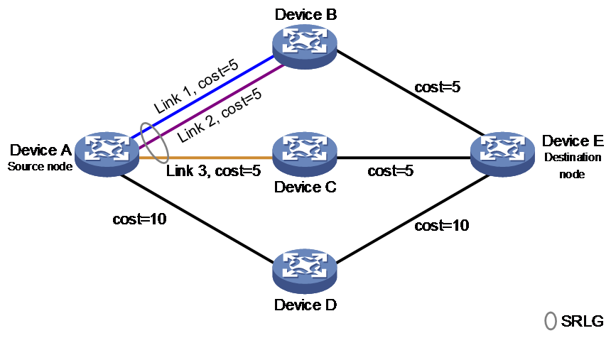
TI-LFA FRR tasks at a glance
To configure TI-LFA FRR, perform the following tasks:
2. (Optional.) Specifying a repair list encapsulation mode for TI-LFA FRR
3. (Optional.) Disabling an interface from participating in TI-LFA calculation
On the source node, disable TI-LFA on the route's output interface to the next hop on the primary path.
4. (Optional.) Enabling FRR microloop avoidance
5. (Optional.) Configuring SR microloop avoidance
¡ Enabling SR microloop avoidance
¡ Specifying an SID list encapsulation mode for SR microloop avoidance
¡ Configuring SR microloop avoidance to encapsulate only strict SIDs in the SID list
Enabling TI-LFA FRR
Enabling IPv6 IS-IS TI-LFA FRR
1. Enter system view.
system-view
2. Enter IS-IS view.
isis process-id
3. Enter IS-IS IPv6 unicast address family view.
address-family ipv6
4. Enable LFA FRR for IPv6 IS-IS.
fast-reroute lfa [ level-1 | level-2 ]
By default, LFA FRR is disabled for IPv6 IS-IS.
5. Enable TI-LFA FRR for IPv6 IS-IS.
fast-reroute ti-lfa [ per-prefix ] [ route-policy route-policy-name | host ] [ level-1 | level-2 ]
By default, TI-LFA FRR is disabled for IPv6 IS-IS.
6. (Optional.) Set the priority for an FRR backup path selection policy.
fast-reroute tiebreaker { lowest-cost | node-protecting | srlg-disjoint } preference preference [ level-1 | level-2 ]
By default, the priority values of the lowest-cost, node-protection, and SRLG-disjoint backup path selection policies are 20, 40, and 10, respectively.
7. (Optional.) Enable Level-1 TI-LFA to use a Level-2 path as the backup path.
inter-level-tilfa level-1 enable [ prefer ]
By default, Level-1 TI-LFA cannot use a Level-2 path as the backup path.
For more information about this command, see Layer 3—IP Routing Command Reference.
Enabling OSPFv3 TI-LFA FRR
1. Enter system view.
system-view
2. Enter OSPFv3 view.
ospfv3 [ process-id | vpn-instance vpn-instance-name ] *
3. Enable LFA FRR for OSPFv3.
fast-reroute { lfa [ abr-only ] | route-policy route-policy-name }
By default, LFA FRR is disabled for OSPFv3.
4. Enable TI-LFA FRR for OSPFv3.
fast-reroute ti-lfa [ per-prefix ] [ route-policy route-policy-name | host ]
By default, TI-LFA FRR is disabled for OSPFv3.
5. (Optional.) Set the priority for FRR backup path selection policies.
fast-reroute tiebreaker { lowest-cost | node-protecting } preference preference
By default, the priority values of the lowest-cost and node-protection backup path selection policies are 20 and 40, respectively.
Specifying a repair list encapsulation mode for TI-LFA FRR
About this task
TI-LFA FRR supports the following repair list encapsulation modes:
· Insert mode—In this mode, the device handles packets as follows when TI-LFA FRR is enabled:
¡ For an SRv6 packet, the device inserts a new SRH between the outer IPv6 header and the original SRH. The new SRH includes all SIDs in the repair list.
¡ For a non-SRv6 IPv6 packet, the device replaces the destination address in the original IPv6 header with the first SID in the repair list and adds an SRH to the packet. The SRH includes all SIDs in the repair list.
· Encap mode—In this mode, the device adds a new outer IPv6 header and SRH to each packet.
¡ The destination address in the new outer IPv6 header is the first SID in the repair list, and the source IPv6 address is manually configured.
¡ The SRH includes all SIDs in the repair list.
Procedure
1. Enter system view.
system-view
2. Enter IS-IS view.
isis process-id
3. Enter IS-IS IPv6 unicast address family view.
address-family ipv6
4. Specify the encap encapsulation mode for TI-LFA FRR.
fast-reroute ti-lfa encaps
By default, TI-LFA FRR uses the insert encapsulation mode.
Disabling an interface from participating in TI-LFA calculation
Disabling an IPv6 IS-IS interface from participating in TI-LFA calculation
1. Enter system view.
system-view
2. Enter the view of IPv6 IS-IS interface.
interface interface-type interface-number
3. Disable the interface from participating in TI-LFA calculation.
isis ipv6 fast-reroute ti-lfa disable [ level-1 | level-2 ]
By default, an IPv6 IS-IS interface participates in TI-LFA calculation.
Disabling an OSPFv3 interface from participating in TI-LFA calculation
1. Enter system view.
system-view
2. Enter the view of OSPFv3 interface.
interface interface-type interface-number
3. Disable the interface from participating in TI-LFA calculation.
ospfv3 fast-reroute ti-lfa disable [ instance instance-id ]
By default, an OSPFv3 interface participates in TI-LFA calculation.
Enabling FRR microloop avoidance
About this task
FRR microloop avoidance provides microloop avoidance after a network failure.
On a network deployed with TI-LFA FRR, when a node or link fails, traffic will be switched to the backup path calculated by TI-LFA. If devices on the backup path have not finished route convergence, a loop is formed between the source node (failed node or the previous node along the link) and a device on the backup path. The loop exists until the devices on the backup path finish route convergence.
To resolve this issue, configure this feature on a node enabled with TI-LFA FRR. FRR microloop avoidance first switches traffic to the backup path calculated by TI-LFA to avoid packet loss after a node or link failure on the optimal path. Then, that node starts an FRR microloop avoidance RIB-update-delay timer configured by the fast-reroute microloop-avoidance rib-update-delay command after it finishes route convergence. The node performs the following operations only after all nodes on the backup path finish route convergence and the timer times out:
· Issues the forwarding path after route convergence to the FIB.
· Switches traffic from the backup path calculated by TI-LFA to the forwarding path after route convergence.
Restrictions and guidelines
If you configure both FRR microloop avoidance and SR microloop avoidance, FRR microloop avoidance takes precedence over SR microloop avoidance. The FRR microloop avoidance RIB-update-delay timer and SR microloop avoidance RIB-update-delay timer are started for the two features, respectively. The following situations exist depending on the configuration of the two timers:
· If the FRR microloop avoidance RIB-update-delay timer is equal to or greater than the SR microloop avoidance RIB-update-delay timer, traffic is switched to the post-convergence path immediately when the former timer times out.
· If the FRR microloop avoidance RIB-update-delay timer is smaller than the SR microloop avoidance RIB-update-delay timer, traffic is switched to the post-convergence path until after the latter timer times out.
Configuring IPv6 IS-IS FRR microloop avoidance
1. Enter system view.
system-view
2. Enter IS-IS view.
isis process-id
3. Enter IS-IS IPv6 unicast address family view.
address-family ipv6
4. Enable FRR microloop avoidance for IS-IS.
fast-reroute microloop-avoidance enable [ level-1 | level-2 ]
By default, FRR microloop avoidance is disabled for IS-IS.
5. (Optional.) Set the FRR microloop avoidance RIB-update-delay time.
fast-reroute microloop-avoidance rib-update-delay delay-time [ level-1 | level-2 ]
By default, the FRR microloop avoidance RIB-update-delay time is 5000 ms.
Configuring OSPFv3 FRR microloop avoidance
1. Enter system view.
system-view
2. Enter OSPFv3 view.
ospfv3 [ process-id | vpn-instance vpn-instance-name ] *
3. Enable FRR microloop avoidance for OSPFv3.
fast-reroute microloop-avoidance enable
By default, FRR microloop avoidance is disabled for OSPFv3.
4. (Optional.) Set the FRR microloop avoidance RIB-update-delay time.
fast-reroute microloop-avoidance rib-update-delay delay-time
By default, the FRR microloop avoidance RIB-update-delay time is 5000 ms.
Enabling SR microloop avoidance
About this task
SR microloop avoidance provides microloop avoidance after both a network failure and a failure recovery.
After a network failure occurs or recovers, route convergence occurs on relevant network devices. Because of nonsimultaneous convergence on network devices, microloops might be formed. After you configure SR microloop avoidance, the devices will forward traffic along the specified path before route convergence is finished on all the relevant network devices. Because the forwarding path is independent of route convergence, microloops are avoided.
Microloop avoidance after a network failure and a failure recovery is as follows:
· When a network failure occurs, a node enabled with this feature issues the calculated forwarding path to the FIB after route convergence and switches the traffic to the forwarding path after the delay timer times out. Before the timer times out, traffic is forwarded along the TI-LFA FRR backup path to avoid microloops.
· When the failure recovers, a node enabled with this feature also calculates an explicit path that contains SIDs except for the primary forwarding path. Before the timer times out, traffic is forwarded along the backup path to avoid microloops.
To ensure sufficient time for IGP to complete route convergence, set the SR microloop avoidance RIB-update-delay time. Before the timer expires, faulty relevant devices will forward traffic along the specified path. Upon expiration of the timer and completion of IGP route convergence, traffic will traverse along the IGP-calculated path.
Restrictions and guidelines
If you configure both FRR microloop avoidance and SR microloop avoidance, FRR microloop avoidance takes precedence over SR microloop avoidance. The FRR microloop avoidance RIB-update-delay timer and SR microloop avoidance RIB-update-delay timer are started for the two features, respectively. The following situations exist depending on the configuration of the two timers:
· If the FRR microloop avoidance RIB-update-delay timer is equal to or greater than the SR microloop avoidance RIB-update-delay timer, traffic is switched to the post-convergence path immediately when the former timer times out.
· If the FRR microloop avoidance RIB-update-delay timer is smaller than the SR microloop avoidance RIB-update-delay timer, traffic is switched to the post-convergence path until after the latter timer times out.
Configuring IPv6 IS-IS SR microloop avoidance
1. Enter system view.
system-view
2. Enter IS-IS view.
isis process-id
3. Enter IS-IS IPv6 unicast address family view.
address-family ipv6
4. Enable SR microloop avoidance for IPv6 IS-IS.
segment-routing microloop-avoidance enable [ level-1 | level-2 ]
By default, SR microloop avoidance is disabled for IPv6 IS-IS.
5. (Optional.) Set the SR microloop avoidance RIB-update-delay time.
segment-routing microloop-avoidance rib-update-delay delay-time [ level-1 | level-2 ]
By default, the SR microloop avoidance RIB-update-delay time is 5000 ms.
Configuring OSPFv3 SR microloop avoidance
1. Enter system view.
system-view
2. Enter OSPFv3 process view.
ospfv3 [ process-id | vpn-instance vpn-instance-name ] *
3. Enable SR microloop avoidance for OSPFv3.
segment-routing microloop-avoidance enable
By default, SR microloop avoidance is disabled for OSPFv3.
4. (Optional.) Set the SR microloop avoidance RIB-update-delay time.
segment-routing microloop-avoidance rib-update-delay delay-time
By default, the SR microloop avoidance RIB-update-delay time is 5000 ms.
Specifying an SID list encapsulation mode for SR microloop avoidance
About this task
SR microloop avoidance supports the following SID list encapsulation modes:
· Insert mode—In this mode, the device handles packets as follows when SR microloop avoidance is enabled:
¡ For an SRv6 packet, the device inserts a new SRH between the outer IPv6 header and the original SRH. The new SRH includes all SIDs in the SID list.
¡ For a non-SRv6 IPv6 packet, the device replaces the destination address in the original IPv6 header with the first SID in the SID list and adds an SRH to the packet. The SRH includes all SIDs in the SID list.
· Encap mode—In this mode, the device adds a new outer IPv6 header and SRH to each packet.
¡ The destination address in the new outer IPv6 header is the first SID in the SID list, and the source IPv6 address is manually configured.
¡ The SRH includes all SIDs in the SID list.
Procedure
1. Enter system view.
system-view
2. Enter IS-IS view.
isis process-id
3. Enter IS-IS IPv6 unicast address family view.
address-family ipv6
4. Specify the encap encapsulation mode for SR microloop avoidance.
segment-routing microloop-avoidance encaps
By default, SR microloop avoidance uses the insert mode.
Configuring SR microloop avoidance to encapsulate only strict SIDs in the SID list
About this task
By default, SR microloop avoidance first calculates the End SID to the P node, and then calculates the End.X SIDs from the P node to the destination node. Then, the SIDs are encapsulated into the SRH in the order of the End SID of the P node and the End.X SIDs from the P node to the destination node.
If multipoint failure exists and the forwarding path is frequently switched, a microloop might exist on the path to the P node identified by the End SID. To resolve this issue, use this feature to strictly constrain the path to the P node.
This feature strictly constrains the path to the P node by calculating an End.X SID to reach the P node. The SIDs are encapsulated into the SID list of the SRH in the order of the End.X SID to the P node and the End.X SIDs from the P node to the destination node.
Procedure
1. Enter system view.
system-view
2. Enter IS-IS view.
isis process-id
3. Enter IS-IS IPv6 unicast address family view.
address-family ipv6
4. Configure SR microloop avoidance to encapsulate only strict SIDs in the SID list.
segment-routing microloop-avoidance strict-sid-only
By default, the strict-SID-only feature is not configured for SR microloop avoidance.
Configuring the SRv6 MTU
About this task
Perform this task to configure one of the following MTUs:
· Path MTU—The maximum IPv6 MTU along the path from the source node to the destination node. The transit nodes do not fragment SRv6 tunneled packets. If a packet is larger than the MTU of the output interface, the packet will be discarded. If the MTU is too small, the bandwidth is not sufficiently used. To address these issues, configure an appropriate SRv6 path MTU.
· Reserved MTU—Reserved MTU on the source node for TI-LFA. When packets are switched to the backup path after the primary path fails, the device reconstructs an IPv6 header and SRH for the packets. As a result, packet drop might occur because the packet size has exceeded the MTU. To resolve this issue, configure a reserved MTU on the source node to reserve bytes for adding a new SRH to SRv6 packets in case of primary path failure.
The size of SRv6 packets sent from the source node is controlled by the SRv6 path MTU, reserved MTU, and the IPv6 MTU of the physical output interface. The source node first finds the smaller value between the SRv6 path MTU and the IPv6 MTU of the physical output interface. Then, it uses the smaller value minus the reserved MTU as the effective MTU of the SRv6 packets.
For example, the SRv6 path MTU is 1600 and the reserved MTU is 100.
· If the IPv6 MTU of the physical output interface is equal to or greater then 1600, the effective MTU is the SRv6 path MTU minus the reserved MTU. In this example, the effective MTU is 1500.
· If the IPv6 MTU of the physical output interface is smaller than 1600, the effective MTU is the IPv6 MTU of the physical output interface minus the reserved MTU. For example, if the IPv6 MTU of the physical output interface is 1500, the effective MTU is 1400.
Restrictions and guidelines
Make sure the active MTU is equal to or greater than 1280 bytes.
Procedure
1. Enter system view.
system-view
2. Enter SRv6 view.
segment-routing ipv6
3. Specify a reserved MTU for SRv6 path MTU.
path-mtu reserved [ reserved-value ]
By default, no reserved MTU is specified for SRv6 path MTU.
4. Configure the SRv6 path MTU.
path-mtu mtu-value
The default SRv6 path MTU is 9600 bytes.
Configuring the SRv6 DiffServ mode
About this task
SRv6 DiffServ mode determines how an SRv6 node processes the IP precedence and DSCP for packets forwarded between an IP network and an SRv6 network. The device supports the following SRv6 DiffServ modes:
· Pipe mode—When a packet enters the SRv6 network, the ingress node adds a new IPv6 header to the original packet. The ingress node ignores the IP precedence or DSCP value in the original packet and uses the value specified by using the service-class argument as the traffic class in the new IPv6 header. In the SRv6 network, SRv6 nodes perform QoS scheduling for the packet based on the specified traffic class. When the packet leaves the SRv6 network, the egress node removes the outer IPv6 header from the packet without modifying the IP precedence or DSCP value in the original packet.
· Short-pipe mode—When a packet enters and leaves the SRv6 network, all SRv6 nodes process the packet in the same way as in pipe mode except for the egress node. After the egress node removes the outer IPv6 header from the packet, it performs QoS scheduling as follows:
¡ If no priority trust mode is configured, the egress node performs QoS scheduling for the packet based on the IP precedence or DSCP value in the original packet.
¡ If a priority trust mode is configured, the egress node performs QoS scheduling for the packet based on the trusted priority.
· Uniform mode—When a packet enters the IPv6 network, the ingress node maps the IP precedence or DSCP value in the original IP header to the outer IPv6 header as the traffic class. When the packet leaves the SRv6 network, the egress node maps the traffic class value in the outer IPv6 header to the original packet as the IP precedence or DSCP value.
Restrictions and guidelines
When you configure the SRv6 DiffServ mode on the source and destination nodes of an SRv6 tunnel, follow these restrictions and guidelines:
· The outbound DiffServ mode on the local end must be the same as the inbound DiffServ mode on the peer end.
· The inbound DiffServ mode on the local end must be the same as the outbound DiffServ mode on the peer end.
For more information about IP precedence and DSCP, see priority mapping configuration in QoS Configuration Guide.
The SRv6 DiffServ mode configuration cannot take effect on an egress node in SRv6-BE mode in the following networks:
· IP L3VPN over SRv6.
· EVPN L3VPN over SRv6.
· EVPN VPWS over SRv6.
· EVPN VPLS over SRv6.
Procedure
1. Enter system view.
system-view
2. Enter SRv6 view.
segment-routing ipv6
3. Configure the SRv6 DiffServ mode.
diffserv-mode { ingress { pipe service-class | short-pipe service-class | uniform } egress { pipe | short-pipe | uniform } | { pipe service-class | short-pipe service-class | uniform } }
By default, the SRv6 DiffServ mode is pipe and the traffic class is 0.
Enabling SNMP notifications for SRv6
About this task
Use this feature to report critical SRv6 events to an NMS. For SRv6 event notifications to be sent correctly, you must also configure SNMP on the device. For more information about SNMP configuration, see Network Management and Monitoring Configuration Guide.
Procedure
1. Enter system view.
system-view
2. Enable SNMP notifications for SRv6.
snmp-agent trap enable srv6
By default, SNMP notifications are disabled for SRv6.
Display and maintenance commands for SRv6
Execute display commands in any view.
|
Task |
Command |
|
Display BGP-EPE information for IPv6 peers. |
display bgp [ instance instance-name ] egress-engineering ipv6 [ ipv6-address ] |
|
Display information about BGP-EPE SRv6 peer sets. |
display bgp egress-engineering srv6 peer-set [ srv6-peer-set-name ] |
|
Display IS-IS SRv6 capability information. |
display isis segment-routing ipv6 capability [ level-1 | level-2 ] [ process-id ] |
|
Display IS-IS SRv6 locator routing information. |
display isis segment-routing ipv6 locator [ ipv6-address prefix-length ] [ flex-algo flex-algo-id | [ level-1 | level-2 ] | verbose ] * [ process-id ] |
|
Display IS-IS SRv6 tunnel interface information. |
display isis srv6 tunnel [ level-1 | level-2 ] [ process-id ] |
|
Display OSPFv3 SRv6 capability information. |
display ospfv3 [ process-id ] segment-routing ipv6 capability |
|
Display OSPFv3 SRv6 locator information. |
display ospfv3 [ process-id ] [ flex-algo flex-algo-id ] segment-routing ipv6 locator [ ipv6-address prefix-length ] |
|
Display OSPFv3 SRv6 tunnel interface information. |
display ospfv3 [ process-id ] srv6 tunnel [ interface-number ] |
|
Display available static SRv6 SIDs in a locator. |
display segment-routing ipv6 available-static-sid locator locator-name [ from begin-value ] |
|
Display brief SRv6 information. |
display segment-routing ipv6 brief |
|
Display SRv6 forwarding entries. |
In standalone mode: display segment-routing ipv6 forwarding [ entry-id [ relation ] | forwarding-type { srv6be | srv6frr | srv6pcpath | srv6pgroup | srv6policy | srv6sfc | srv6sidlist | srv6sids } ] [ slot slot-number ] In IRF mode: display segment-routing ipv6 forwarding [ entry-id [ relation ] | forwarding-type { srv6be | srv6frr | srv6pcpath | srv6pgroup | srv6policy | srv6sfc | srv6sidlist | srv6sids } ] [ chassis chassis-number slot slot-number ] |
|
Display information about the SRv6 local SID forwarding table. |
display segment-routing ipv6 local-sid [ locator locator-name ] [ end | end-am | end-as | end-b6encaps | end-b6encapsred | end-b6insert | end-b6insertred | end-bier | end-coc-none | end-coc32 | end-dt2m | end-dt2u | end-dt2ul | end-dx2 | end-dx2-auto | end-dx2l | end-m | end-op | end-psid | end-r | end-rgb | end-t | end-xsid ] [ owner owner ] [ sid ] display segment-routing ipv6 local-sid [ locator locator-name ] [ end-dt4 | end-dt46 | end-dt6 | end-dx4 | end-dx6 | src-dt4 | src-dt6 ] [ [ owner owner ] sid | vpn-instance vpn-instance-name ] display segment-routing ipv6 local-sid [ locator locator-name ] [ end-x | end-x-coc32 | end-x-coc-none ] [ sid | interface interface-type interface-number [ nexthop nexthop-ipv6-address ] ] [ owner owner ] |
|
Display the local G-SID entries generated based on a local SID in the 16-bit compression scenario. |
display segment-routing ipv6 local-sid lib [ locator locator-name ] [ end | end-b6encaps | end-b6encapsred | end-b6insert | end-b6insertred | end-coc-none | end-dt2m | end-dt2u | end-dt2ul | end-dx2 | end-dx2l | end-x | end-x-coc-none ] [ owner owner ] [ sid ] display segment-routing ipv6 local-sid lib [ locator locator-name ] [ end-dt4 | end-dt46 | end-dt6 | end-dx4 | end-dx6 ] [ owner owner ] [ sid ] |
|
Display statistics about SRv6 SIDs allocated for each protocol. |
display segment-routing ipv6 local-sid statistics [ locator [ locator-name ] ] |
|
Display SRv6 locator information. |
display segment-routing ipv6 locator [ locator-name ] |
|
Display SRv6 locator configuration and statistics about allocated SRv6 SIDs in locators. |
display segment-routing ipv6 locator-statistics [ locator-name ] |
|
Display remote SRv6 locator information. |
display segment-routing ipv6 remote-locator [ remote-locator-name ] |
|
Display remote SRv6 SID information. |
display segment-routing ipv6 remote-sid { end-dx2 | end-dx2l } [ sid ] |
SRv6 configuration examples
Example: Configuring IPv6 IS-IS TI-LFA FRR
Network configuration
As shown in Figure 32, complete the following tasks to implement TI-LFA FRR:
· Configure IPv6 IS-IS on Device A, Device B, Device C, and Device D to achieve network level connectivity.
· Configure IS-IS SRv6 on Device A, Device B, Device C, and Device D.
· Configure TI-LFA FRR to remove the loop on Link B and to implement fast traffic switchover to Link B when Link A fails.
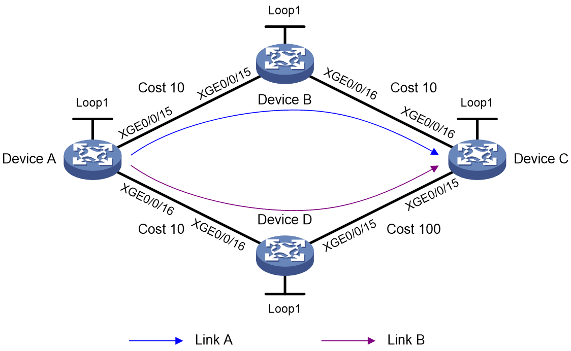
Table 2 Interface and IP address assignment
|
Device |
Interface |
IP address |
Device |
Interface |
IP address |
|
Device A |
Loop1 |
1::1/128 |
Device B |
Loop1 |
2::2/128 |
|
|
XGE0/0/15 |
2000:1::1/64 |
|
XGE0/0/15 |
2000:1::2/64 |
|
|
XGE0/0/16 |
2000:4::1/64 |
|
XGE0/0/16 |
2000:2::2/64 |
|
Device C |
Loop1 |
3::3/128 |
Device D |
Loop1 |
4::4/128 |
|
|
XGE0/0/15 |
2000:3::3/64 |
|
XGE0/0/15 |
2000:3::4/64 |
|
|
XGE0/0/16 |
2000:2::3/64 |
|
XGE0/0/16 |
2000:4::4/64 |
Procedure
1. Configure IPv6 addresses and prefixes for interfaces. (Details not shown.)
2. Configure Device A:
# Configure IPv6 IS-IS to achieve network level connectivity and set the IS-IS cost style to wide.
<DeviceA> system-view
[DeviceA] isis 1
[DeviceA-isis-1] network-entity 00.0000.0000.0001.00
[DeviceA-isis-1] cost-style wide
[DeviceA-isis-1] address-family ipv6
[DeviceA-isis-1-ipv6] quit
[DeviceA-isis-1] quit
[DeviceA] interface ten-gigabitethernet 0/0/15
[DeviceA-Ten-GigabitEthernet0/0/15] isis ipv6 enable 1
[DeviceA-Ten-GigabitEthernet0/0/15] isis cost 10
[DeviceA-Ten-GigabitEthernet0/0/15] isis ipv6 cost 10
[DeviceA-Ten-GigabitEthernet0/0/15] quit
[DeviceA] interface ten-gigabitethernet 0/0/16
[DeviceA-Ten-GigabitEthernet0/0/16] isis ipv6 enable 1
[DeviceA-Ten-GigabitEthernet0/0/16] isis cost 10
[DeviceA-Ten-GigabitEthernet0/0/16] isis ipv6 cost 10
[DeviceA-Ten-GigabitEthernet0/0/16] quit
[DeviceA] interface loopback 1
[DeviceA-LoopBack1] isis ipv6 enable 1
[DeviceA-LoopBack1] quit
# Enable SRv6 and configure a locator.
[DeviceA] segment-routing ipv6
[DeviceA-segment-routing-ipv6] locator aaa ipv6-prefix 11:: 64 static 32
[DeviceA-segment-routing-ipv6-locator-aaa] quit
[DeviceA-segment-routing-ipv6] quit
# Configure IPv6 IS-IS TI-LFA FRR, and enable SR microloop avoidance.
[DeviceA] isis 1
[DeviceA-isis-1] address-family ipv6
[DeviceA-isis-1-ipv6] fast-reroute lfa
[DeviceA-isis-1-ipv6] fast-reroute ti-lfa
[DeviceA-isis-1-ipv6] fast-reroute microloop-avoidance enable
[DeviceA-isis-1-ipv6] segment-routing microloop-avoidance enable
# Apply the locator to the IPv6 IS-IS process.
[DeviceA-isis-1-ipv6] segment-routing ipv6 locator aaa
[DeviceA-isis-1-ipv6] quit
[DeviceA-isis-1] quit
3. Configure Device B:
# Configure IPv6 IS-IS to achieve network level connectivity and set the IS-IS cost style to wide.
<DeviceB> system-view
[DeviceB] isis 1
[DeviceB-isis-1] network-entity 00.0000.0000.0002.00
[DeviceB-isis-1] cost-style wide
[DeviceB-isis-1] address-family ipv6
[DeviceB-isis-1-ipv6] quit
[DeviceB-isis-1] quit
[DeviceB] interface ten-gigabitethernet 0/0/15
[DeviceB-Ten-GigabitEthernet0/0/15] isis ipv6 enable 1
[DeviceB-Ten-GigabitEthernet0/0/15] isis cost 10
[DeviceB-Ten-GigabitEthernet0/0/15] isis ipv6 cost 10
[DeviceB-Ten-GigabitEthernet0/0/15] quit
[DeviceB] interface ten-gigabitethernet 0/0/16
[DeviceB-Ten-GigabitEthernet0/0/16] isis ipv6 enable 1
[DeviceB-Ten-GigabitEthernet0/0/16] isis cost 10
[DeviceB-Ten-GigabitEthernet0/0/16] isis ipv6 cost 10
[DeviceB-Ten-GigabitEthernet0/0/16] quit
[DeviceB] interface loopback 1
[DeviceB-LoopBack1] isis ipv6 enable 1
[DeviceB-LoopBack1] quit
# Enable SRv6 and configure a locator.
[DeviceB] segment-routing ipv6
[DeviceB-segment-routing-ipv6] locator bbb ipv6-prefix 22:: 64 static 32
[DeviceB-segment-routing-ipv6-locator-bbb] quit
[DeviceB-segment-routing-ipv6] quit
# Configure IPv6 IS-IS TI-LFA FRR.
[DeviceB] isis 1
[DeviceB-isis-1] address-family ipv6
[DeviceB-isis-1-ipv6] fast-reroute lfa
[DeviceB-isis-1-ipv6] fast-reroute ti-lfa
# Apply the locator to the IPv6 IS-IS process.
[DeviceB-isis-1-ipv6] segment-routing ipv6 locator bbb
[DeviceB-isis-1-ipv6] quit
[DeviceB-isis-1] quit
4. Configure Device C:
# Configure IPv6 IS-IS to achieve network level connectivity and set the IS-IS cost style to wide.
<DeviceC> system-view
[DeviceC] isis 1
[DeviceC-isis-1] network-entity 00.0000.0000.0003.00
[DeviceC-isis-1] cost-style wide
[DeviceC-isis-1] address-family ipv6
[DeviceC-isis-1-ipv6] quit
[DeviceC-isis-1] quit
[DeviceC] interface ten-gigabitethernet 0/0/15
[DeviceC-Ten-GigabitEthernet0/0/15] isis ipv6 enable 1
[DeviceC-Ten-GigabitEthernet0/0/15] isis cost 100
[DeviceC-Ten-GigabitEthernet0/0/15] isis ipv6 cost 100
[DeviceC-Ten-GigabitEthernet0/0/15] quit
[DeviceC] interface ten-gigabitethernet 0/0/16
[DeviceC-Ten-GigabitEthernet0/0/16] isis ipv6 enable 1
[DeviceC-Ten-GigabitEthernet0/0/16] isis cost 10
[DeviceC-Ten-GigabitEthernet0/0/16] isis ipv6 cost 10
[DeviceC-Ten-GigabitEthernet0/0/16] quit
[DeviceC] interface loopback 1
[DeviceC-LoopBack1] isis ipv6 enable 1
[DeviceC-LoopBack1] quit
# Enable SRv6 and configure a locator.
[DeviceC] segment-routing ipv6
[DeviceC-segment-routing-ipv6] locator ccc ipv6-prefix 33:: 64 static 32
[DeviceC-segment-routing-ipv6-locator-ccc] quit
[DeviceC-segment-routing-ipv6] quit
# Configure IPv6 IS-IS TI-LFA FRR.
[DeviceC] isis 1
[DeviceC-isis-1] address-family ipv6
[DeviceC-isis-1-ipv6] fast-reroute lfa
[DeviceC-isis-1-ipv6] fast-reroute ti-lfa
# Apply the locator to the IPv6 IS-IS process.
[DeviceC-isis-1-ipv6] segment-routing ipv6 locator ccc
[DeviceC-isis-1-ipv6] quit
[DeviceC-isis-1] quit
5. Configure Device D:
# Configure IPv6 IS-IS to achieve network level connectivity and set the IS-IS cost style to wide.
<DeviceD> system-view
[DeviceD] isis 1
[DeviceD-isis-1] network-entity 00.0000.0000.0004.00
[DeviceD-isis-1] cost-style wide
[DeviceD-isis-1] address-family ipv6
[DeviceD-isis-1-ipv6] quit
[DeviceD-isis-1] quit
[DeviceD] interface ten-gigabitethernet 0/0/15
[DeviceD-Ten-GigabitEthernet0/0/15] isis ipv6 enable 1
[DeviceD-Ten-GigabitEthernet0/0/15] isis cost 100
[DeviceD-Ten-GigabitEthernet0/0/15] isis ipv6 cost 100
[DeviceD-Ten-GigabitEthernet0/0/15] quit
[DeviceD] interface ten-gigabitethernet 0/0/16
[DeviceD-Ten-GigabitEthernet0/0/16] isis ipv6 enable 1
[DeviceD-Ten-GigabitEthernet0/0/16] isis cost 10
[DeviceD-Ten-GigabitEthernet0/0/16] isis ipv6 cost 10
[DeviceD-Ten-GigabitEthernet0/0/16] quit
[DeviceD] interface loopback 1
[DeviceD-LoopBack1] isis ipv6 enable 1
[DeviceD-LoopBack1] quit
# Enable SRv6 and configure a locator.
[DeviceD] segment-routing ipv6
[DeviceD-segment-routing-ipv6] locator ddd ipv6-prefix 44:: 64 static 32
[DeviceD-segment-routing-ipv6-locator-ddd] quit
[DeviceD-segment-routing-ipv6] quit
# Configure IPv6 IS-IS TI-LFA FRR.
[DeviceD] isis 1
[DeviceD-isis-1] address-family ipv6
[DeviceD-isis-1-ipv6] fast-reroute lfa
[DeviceD-isis-1-ipv6] fast-reroute ti-lfa
# Apply the locator to the IPv6 IS-IS process.
[DeviceD-isis-1-ipv6] segment-routing ipv6 locator ddd
[DeviceD-isis-1-ipv6] quit
[DeviceD-isis-1] quit
Verifying the configuration
# Display IPv6 IS-IS routing information for 3::3/128.
[DeviceA] display isis route ipv6 3::3 128 verbose
Route information for IS-IS(1)
------------------------------
Level-1 IPv6 forwarding table
-----------------------------
IPv6 dest : 3::3/128
Flag : R/L/- Cost : 20
Admin tag : - Src count : 2
Nexthop : FE80::4449:7CFF:FEE0:206
NexthopFlag : -
Interface : XGE0/0/15
TI-LFA:
Interface : XGE0/0/16
BkNextHop : FE80::4449:91FF:FE42:407
LsIndex : 0x80000001
Backup label stack(top->bottom): {44::1:0:1}
Nib ID : 0x24000006
Flags: D-Direct, R-Added to Rib, L-Advertised in LSPs, U-Up/Down Bit Set
The output shows TI-LFA backup next hop information.
Example: Configuring SRv6 BGP-EPE
Network configuration
As shown in Figure 33, VPN private network service routes 11.11.11.11/32 and 66.66.66.66/32 are in AS 100 and AS 200, respectively. Deploy BGP-EPE to enable end-to-end inter-domain communication between these two service addresses. The inter-domain tunnel is an SRv6 TE Policy. Complete the following tasks to implement BGP-EPE:
· Configure IPv6 IS-IS on PE 1, P 1, and ASBR 1 to achieve network level connectivity.
· Configure IPv6 IS-IS on PE 2, P 2, and ASBR 2 to achieve network level connectivity.
· Deploy the SRv6-based BGP-EPE between ASBR 1 and ASBR 2. BGP-EPE assigns Peer-Adj SIDs to inter-domain links.
· Establish a BGP-LS peer relationship between ASBR 1 and the controller and ASBR 2 and the controller. They advertise intra-AS and inter-AS link topology information to the controller.
· The controller calculates the end-to-end SRv6 TE policy tunnel based on link topology information. It then issues the tunnel to PE 1 and PE 2 through a BGP SRv6 policy to form an end-to-end tunnel.
· After BGP advertises VPN private network service routes, the service traffic is transported by the inter-domain SRv6 TE policy.
For more information about configuration on the controller, see the user guide relevant to the controller.
Network diagram
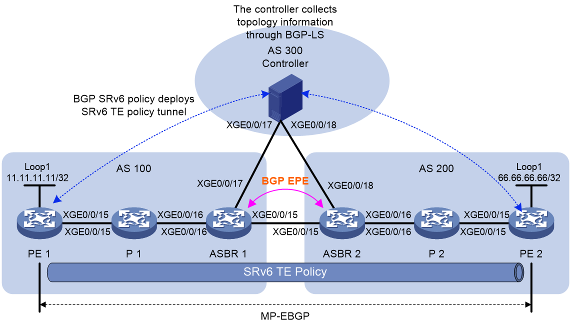
|
Device |
Interface |
IP address |
Device |
Interface |
IP address |
|
PE 1 |
Loop0 |
1::1/128 |
PE 2 |
Loop0 |
6::6/128 |
|
|
Loop1 |
11.11.11.11/32 |
|
Loop1 |
66.66.66.66/32 |
|
|
XGE0/0/15 |
12::1/120 |
|
XGE0/0/15 |
56::2/120 |
|
P 1 |
Loop0 |
2::2/128 |
P 2 |
Loop0 |
5::5/128 |
|
|
XGE0/0/15 |
12::2/120 |
|
XGE0/0/15 |
56::1/120 |
|
|
XGE0/0/16 |
23::1/120 |
|
XGE0/0/16 |
45::2/120 |
|
ASBR 1 |
Loop0 |
3::3/128 |
ASBR 2 |
Loop0 |
4::4/128 |
|
|
XGE0/0/15 |
34::1/120 |
|
XGE0/0/15 |
34::2/120 |
|
|
XGE0/0/16 |
23::2/120 |
|
XGE0/0/16 |
45::1/120 |
|
|
XGE0/0/16 |
37::1/120 |
|
XGE0/0/16 |
47::1/120 |
|
Controller |
Loop0 |
7::7/128 |
|
|
|
|
|
XGE0/0/16 |
37::2/120 |
|
|
|
|
|
XGE0/0/16 |
47::2/120 |
|
|
|
Procedure
1. Configure PE 1:
# Configure IPv6 IS-IS to achieve network level connectivity.
<Sysname> system-view
[Sysname] sysname PE1
[PE1] isis 1
[PE1-isis-1] is-level level-1
[PE1-isis-1] cost-style wide
[PE1-isis-1] network-entity 10.0000.0000.0001.00
[PE1-isis-1] address-family ipv6 unicast
[PE1-isis-1-ipv6] quit
[PE1-isis-1] quit
[PE1] interface loopback 0
[PE1-LoopBack0] ipv6 address 1::1 128
[PE1-LoopBack0] isis ipv6 enable 1
[PE1-LoopBack0] quit
[PE1] interface ten-gigabitethernet 0/0/15
[PE1-Ten-GigabitEthernet0/0/15] ipv6 address 12::1 120
[PE1-Ten-GigabitEthernet0/0/15] isis ipv6 enable 1
[PE1-Ten-GigabitEthernet0/0/15] quit
# Configure a VPN instance and VPN service address.
[PE1] ip vpn-instance vpna
[PE1-vpn-instance-vpna] route-distinguisher 100:1
[PE1-vpn-instance-vpna] vpn-target 100:1
[PE1-vpn-instance-vpna] quit
[PE1] interface loopback 1
[PE1-LoopBack1] ip binding vpn-instance vpna
[PE1-LoopBack1] ip address 11.11.11.11 32
[PE1-LoopBack1] quit
# Establish a BGP VPNv4 peer relationship between the PEs.
[PE1] bgp 100
[PE1-bgp-default] router-id 1.1.1.1
[PE1-bgp-default] peer 6::6 as-number 200
[PE1-bgp-default] peer 6::6 connect-interface LoopBack0
[PE1-bgp-default] peer 6::6 ebgp-max-hop 255
[PE1-bgp-default] address-family vpnv4
[PE1-bgp-default-vpnv4] peer 6::6 enable
[PE1-bgp-default-vpnv4] quit
[PE1-bgp-default] quit
# Enable SRv6, configure an SRv6 locator and local SRv6 SID, and apply the SRv6 locator to the IS-IS process to implement SRv6 locator connectivity.
[PE1] segment-routing ipv6
[PE1-segment-routing-ipv6] encapsulation source-address 1::1
[PE1-segment-routing-ipv6] locator a ipv6-prefix 100:: 64 static 16
[PE1-segment-routing-ipv6-locator-a] opcode 1 end no-flavor
[PE1-segment-routing-ipv6-locator-a] quit
[PE1-segment-routing-ipv6] quit
[PE1] isis 1
[PE1-isis-1] address-family ipv6 unicast
[PE1-isis-1-ipv6] segment-routing ipv6 locator a
[PE1-isis-1-ipv6] quit
[PE1-isis-1] quit
# Redistribute VPN service routes from PE 1 and PE 2 into BGP and advertise these routes with the Prefix-SID attribute through BGP VPNv4 to each other. Recurse the routes to the SRv6 TE policy and use SRv6 BE to protect the SRv6 TE policy.
[PE1] bgp 100
[PE1-bgp-default] address-family vpnv4
[PE1-bgp-default-vpnv4] peer 6::6 prefix-sid
[PE1-bgp-default-vpnv4] quit
[PE1-bgp-default] ip vpn-instance vpna
[PE1-bgp-default-vpna] address-family ipv4 unicast
[PE1-bgp-default-ipv4-vpna] segment-routing ipv6 locator a
[PE1-bgp-default-ipv4-vpna] segment-routing ipv6 traffic-engineering best-effort
[PE1-bgp-default-ipv4-vpna] import-route direct
[PE1-bgp-default-ipv4-vpna] quit
[PE1-bgp-default-vpna] quit
[PE1-bgp-default] quit
|
|
CAUTION: If you specify SRv6 BE as the FRR protection method when you configure the segment-routing ipv6 traffic-engineering command, you must advertise the SRv6 locator used for assigning VPN service SIDs on the remote PE device into the AS to which the local PE belongs. If you fail to do so, SRv6 BE route recursion will fail and service traffic will be disrupted. If you do not specify SRv6 BE as the FRR protection method when you configure the segment-routing ipv6 traffic-engineering command, you do not need to advertise such SRv6 locator. |
# Configure SRv6 TE on PE 1.
[PE1] segment-routing ipv6
[PE1-segment-routing-ipv6] traffic-engineering
[PE1-srv6-te] srv6-policy locator a
[PE1-srv6-te] quit
[PE1-segment-routing-ipv6] quit
# Configure PE 1 to establish a BGP SRv6 policy peer relationship with the controller to receive SRv6 TE policy issued by the controller.
[PE1] bgp 100
[PE1-bgp-default] peer 7::7 as-number 300
[PE1-bgp-default] peer 7::7 connect-interface LoopBack0
[PE1-bgp-default] peer 7::7 ebgp-max-hop 255
[PE1-bgp-default] address-family ipv6 sr-policy
[PE1-bgp-default-srpolicy-ipv6] peer 7::7 enable
[PE1-bgp-default-srpolicy-ipv6] quit
[PE1-bgp-default] quit
# On the PE, execute the display bgp routing-table ipv6 sr-policy command to display the BGP SRv6 policy routes advertised by the controller. The output shows that the endpoint IPv6 address, color, and candidate path preference of the BGP IPv6 SR policy are 6::6 (loopback0 address on PE 2), 200, and 100, respectively.
[PE1] display bgp routing-table ipv6 sr-policy end-point ipv6 6::6
Total number of routes: 1
BGP local router ID is 1.1.1.1
Status codes: * - valid, > - best, d - dampened, h - history,
s - suppressed, S - stale, i - internal, e - external
a - additional-path
Origin: i - IGP, e - EGP, ? - incomplete
* >e Network : [100][200][6::6]/192
NextHop : 7::7 LocPrf :
PrefVal : 0 OutLabel : NULL
MED : 0
Path/Ogn: 300i
# Enable SBFD for all SRv6 TE policies and configure the local discriminator and remote discriminator of the session.
[PE1] sbfd source-ipv6 1::1
[PE1] sbfd local-discriminator 1000002
[PE1] segment-routing ipv6
[PE1-segment-routing-ipv6] traffic-engineering
[PE1-srv6-te] srv6-policy sbfd remote 1000001
[PE1-srv6-te] quit
[PE1-segment-routing-ipv6] quit
# Configure a routing policy and tunnel policy to add color extended community attribute 00:200 to BGP routes. Configure the routing policy to steer VPN service traffic to the specified SRv6 TE policy. In addition, configure a tunnel policy to ensure that the SRv6 TE policy is preferred during tunnel selection.
[PE1] route-policy color permit node 10
[PE1-route-policy-color-10] apply extcommunity color 00:200 additive
[PE1-route-policy-color-10] quit
[PE1] bgp 100
[PE1-bgp-default] address-family vpnv4
[PE1-bgp-default-vpnv4] peer 6::6 route-policy color export
[PE1-bgp-default-vpnv4] peer 6::6 advertise-community
[PE1-bgp-default-vpnv4] quit
[PE1-bgp-default] quit
[PE1] tunnel-policy a
[PE1-tunnel-policy-a] select-seq srv6-policy load-balance-number 1
[PE1-tunnel-policy-a] quit
[PE1] ip vpn-instance vpna
[PE1-vpn-instance-vpna] tnl-policy a
[PE1-vpn-instance-vpna] quit
2. Configure P1:
# Configure IPv6 IS-IS to achieve network level connectivity.
<Sysname> system-view
[Sysname] sysname P1
[P1] isis 1
[P1-isis-1] is-level level-1
[P1-isis-1] cost-style wide
[P1-isis-1] network-entity 10.0000.0000.0002.00
[P1-isis-1] address-family ipv6 unicast
[P1-isis-1-ipv6] quit
[P1-isis-1] quit
[P1] interface loopback 0
[P1-LoopBack0] ipv6 address 2::2 128
[P1-LoopBack0] isis ipv6 enable 1
[P1-LoopBack0] quit
[P1] interface ten-gigabitethernet 0/0/15
[P1-Ten-GigabitEthernet0/0/15] ipv6 address 12::2 120
[P1-Ten-GigabitEthernet0/0/15] isis ipv6 enable 1
[P1-Ten-GigabitEthernet0/0/15] quit
[P1] interface ten-gigabitethernet 0/0/16
[P1-Ten-GigabitEthernet0/0/16] ipv6 address 23::1 120
[P1-Ten-GigabitEthernet0/0/16] isis ipv6 enable 1
[P1-Ten-GigabitEthernet0/0/16] quit
# Configure a locator and enable IS-IS to advertise that locator.
[P1] segment-routing ipv6
[P1-segment-routing-ipv6] locator b ipv6-prefix 200:: 64 static 16
[P1-segment-routing-ipv6-locator-b] opcode 1 end no-flavor
[P1-segment-routing-ipv6-locator-b] quit
[P1-segment-routing-ipv6] quit
[P1] isis 1
[P1-isis-1] address-family ipv6 unicast
[P1-isis-1-ipv6] segment-routing ipv6 locator b
[P1-isis-1-ipv6] quit
[P1-isis-1] quit
3. Configure ASBR 1
# Configure IPv6 IS-IS to achieve network level connectivity. Import the loopback0 interface address and SRv6 locator of the remote PE device advertised by the EBGP neighbor into IGP to ensure correct route recursion for both SRv6 TE and SRv6 BE.
<Sysname> system-view
[Sysname] sysname ASBR1
[ASBR1] isis 1
[ASBR1-isis-1] is-level level-1
[ASBR1-isis-1] cost-style wide
[ASBR1-isis-1] network-entity 10.0000.0000.0003.00
[ASBR1-isis-1] address-family ipv6 unicast
[ASBR1-isis-1-ipv6] import-route bgp4+ level-1
[ASBR1-isis-1-ipv6] quit
[ASBR1-isis-1] quit
[ASBR1] interface loopback 0
[ASBR1-LoopBack0] ipv6 address 3::3 128
[ASBR1-LoopBack0] isis ipv6 enable 1
[ASBR1-LoopBack0] quit
[ASBR1] interface ten-gigabitethernet 0/0/15
[ASBR1-Ten-GigabitEthernet0/0/15] ipv6 address 34::1 120
[ASBR1-Ten-GigabitEthernet0/0/15] quit
[ASBR1] interface ten-gigabitethernet 0/0/16
[ASBR1-Ten-GigabitEthernet0/0/16] ipv6 address 23::2 120
[ASBR1-Ten-GigabitEthernet0/0/16] isis ipv6 enable 1
[ASBR1-Ten-GigabitEthernet0/0/16] quit
[ASBR1] interface gigabitethernet 1/0/3
[ASBR1-GigabitEthernet1/0/3] ipv6 address 37::1 120
[ASBR1-GigabitEthernet1/0/3] quit
# Configure a locator and enable IS-IS to advertise that locator.
[ASBR1] segment-routing ipv6
[ASBR1-segment-routing-ipv6] locator c ipv6-prefix 300:: 64 static 16
[ASBR1-segment-routing-ipv6-locator-c] opcode 1 end no-flavor
[ASBR1-segment-routing-ipv6-locator-c] quit
[ASBR1-segment-routing-ipv6] quit
[ASBR1] isis 1
[ASBR1-isis-1] address-family ipv6 unicast
[ASBR1-isis-1-ipv6] segment-routing ipv6 locator c
[ASBR1-isis-1-ipv6] quit
[ASBR1-isis-1] quit
# Configure ASBR 1, ASBR 2, and the controller as EBGP peers to advertise the loopback0 interface address and SRv6 locator prefix of their local PE to each other.
[ASBR1] bgp 100
[ASBR1-bgp-default] router-id 3.3.3.3
[ASBR1-bgp-default] peer 34::2 as-number 200
[ASBR1-bgp-default] peer 37::2 as-number 300
[ASBR1-bgp-default] address-family ipv6
[ASBR1-bgp-default-ipv6] network 1::1 128
[ASBR1-bgp-default-ipv6] network 100:: 64
[ASBR1-bgp-default-ipv6] peer 34::2 enable
[ASBR1-bgp-default-ipv6] peer 37::2 enable
[ASBR1-bgp-default-ipv6] quit
[ASBR1-bgp-default] quit
# Configure BGP EPE on ASBR 1 and ASBR 2, and manually specify the Peer Adj-SIDs for inter-AS links.
[ASBR1] bgp 100
[ASBR1-bgp-default] segment-routing ipv6 egress-engineering locator c
[ASBR1-bgp-default] peer 34::2 egress-engineering srv6 static-sid no-flavor 300::101
[ASBR1-bgp-default] quit
# On ASBR 1, execute the display bgp egress-engineering ipv6 command to display the Peer Adj-SIDs that BGP EPE assigns to inter-AS links.
[ASBR1] display bgp egress-engineering ipv6
BGP peering segment type: Node-Adjacency
Peer NodeAdj : 34::2
Local ASNumber : 100
Remote ASNumber : 200
Local RouterID : 3.3.3.3
Remote RouterID : 4.4.4.4
Interface : XGE0/0/15
OriginNexthop : 34::2
RelyNexthop : 34::2
StaticSID(NO-FLAVOR) : 300::101
SID(PSP) : 300::1:5
SID(NO-FLAVOR) : 300::101
SID(PSP,USP,USD) : 300::1:6
# Configure ASBR 1 to establish a BGP LS peer relationship with the controller and advertise intra-AS and inter-AS link topology information to the controller. The controller then calculates the SRv6 TE policy.
[ASBR1] mpls lsr-id 3.3.3.3
[ASBR1] mpls te
[ASBR1-te] quit
[ASBR1] bgp 100
[ASBR1-bgp-default] peer 37::2 as-number 300
[ASBR1-bgp-default] address-family link-state
[ASBR1-bgp-default-ls] peer 37::2 enable
[ASBR1-bgp-default-ls] domain-distinguisher 100:3.3.3.3
[ASBR1-bgp-default-ls] quit
[ASBR1-bgp-default] quit
[ASBR1] isis 1
[ASBR1-isis-1] mpls te enable
[ASBR1-isis-1] distribute bgp-ls
[ASBR1-isis-1] address-family ipv6 unicast
[ASBR1-isis-1-ipv6] advertise link-attributes
[ASBR1-isis-1-ipv6] quit
[ASBR1-isis-1] quit
# On ASBR 1, execute the display bgp link-state command to display intra-domain and inter-AS link topology information.
4. Configure ASBR 2:
# Configure IPv6 IS-IS to achieve network level connectivity. Redistribute the loopback0 interface address and SRv6 locator of the remote PE device advertised by the EBGP neighbor into IGP to ensure correct route recursion for both SRv6 TE and SRv6 BE.
<Sysname> system-view
[Sysname] sysname ASBR2
[ASBR2] isis 1
[ASBR2] is-level level-1
[ASBR2-isis-1] cost-style wide
[ASBR2-isis-1] network-entity 20.0000.0000.0004.00
[ASBR2-isis-1] address-family ipv6 unicast
[ASBR2-isis-1] import-route bgp4+ level-1
[ASBR2-isis-1-ipv6] quit
[ASBR2-isis-1] quit
[ASBR2] interface loopback 0
[ASBR2-LoopBack0] ipv6 address 4::4 128
[ASBR2-LoopBack0] isis ipv6 enable 1
[ASBR2-LoopBack0] quit
[ASBR2] interface ten-gigabitethernet 0/0/15
[ASBR2-Ten-GigabitEthernet0/0/15] ipv6 address 34::2 120
[ASBR2-Ten-GigabitEthernet0/0/15] quit
[ASBR2] interface ten-gigabitethernet 0/0/16
[ASBR2-Ten-GigabitEthernet0/0/16] ipv6 address 45::1 120
[ASBR2-Ten-GigabitEthernet0/0/16] isis ipv6 enable 1
[ASBR2-Ten-GigabitEthernet0/0/16] quit
[ASBR2] interface ten-gigabitethernet 0/0/15
[ASBR2-Ten-GigabitEthernet0/0/18] ipv6 address 47::1 120
[ASBR2-Ten-GigabitEthernet0/0/18] quit
# Configure a locator and enable IS-IS to advertise that locator.
[ASBR2] segment-routing ipv6
[ASBR2-segment-routing-ipv6] locator d ipv6-prefix 400:: 64 static 16
[ASBR2-segment-routing-ipv6-locator-d] opcode 1 end no-flavor
[ASBR2-segment-routing-ipv6-locator-d] quit
[ASBR2-segment-routing-ipv6] quit
[ASBR2] isis 1
[ASBR2-isis-1] address-family ipv6 unicast
[ASBR2-isis-1-ipv6] segment-routing ipv6 locator d
[ASBR2-isis-1-ipv6] quit
[ASBR2-isis-1] quit
# Configure ASBR 2, ASBR 1, and the controller as EBGP peers to advertise the loopback0 interface address and SRv6 locator prefix of their local PE to each other.
[ASBR2] bgp 200
[ASBR2-bgp-default] router-id 4.4.4.4
[ASBR2-bgp-default] peer 34::1 as-number 100
[ASBR2-bgp-default] peer 47::2 as-number 300
[ASBR2-bgp-default] address-family ipv6
[ASBR2-bgp-default-ipv6] network 6::6 128
[ASBR2-bgp-default-ipv6] network 600:: 64
[ASBR2-bgp-default-ipv6] peer 34::1 enable
[ASBR2-bgp-default-ipv6] peer 47::2 enable
[ASBR2-bgp-default-ipv6] quit
[ASBR2-bgp-default] quit
# Configure BGP EPE on ASBR 1 and ASBR 2, and manually specify the Peer Adj-SIDs for inter-AS links.
[ASBR2] bgp 200
[ASBR2-bgp-default] segment-routing ipv6 egress-engineering locator d
[ASBR2-bgp-default] peer 34::1 egress-engineering srv6 static-sid no-flavor 400::101
[ASBR2-bgp-default] quit
# On ASBR 2, execute the display bgp egress-engineering ipv6 command to display the Peer Adj-SIDs that BGP EPE assigns to inter-AS links.
[ASBR2] display bgp egress-engineering ipv6
BGP peering segment type: Node-Adjacency
Peer NodeAdj : 34::1
Local ASNumber : 200
Remote ASNumber : 100
Local RouterID : 4.4.4.4
Remote RouterID : 3.3.3.3
Interface : XGE0/0/15
OriginNexthop : 34::1
RelyNexthop : 34::1
StaticSID(NO-FLAVOR) : 400::101
SID(PSP) : 400::1:2
SID(NO-FLAVOR) : 400::101
SID(PSP,USP,USD) : 400::1:3
# Configure ASBR 2 to establish a BGP LS peer relationship with the controller and advertise intra-AS and inter-AS link topology information to the controller. The controller then calculates the SRv6 TE policy.
[ASBR1] mpls lsr-id 3.3.3.3
[ASBR1] mpls te
[ASBR1-te] quit
[ASBR2] bgp 200
[ASBR2-bgp-default] peer 47::2 as-number 300
[ASBR2-bgp-default] address-family link-state
[ASBR2-bgp-default-ls] peer 47::2 enable
[ASBR2-bgp-default-ls] domain-distinguisher 200:4.4.4.4
[ASBR2-bgp-default-ls] quit
[ASBR2-bgp-default] quit
[ASBR2] isis 1
[ASBR2-isis-1] mpls te enable
[ASBR2-isis-1] distribute bgp-ls
[ASBR2-isis-1] address-family ipv6 unicast
[ASBR2-isis-1-ipv6] advertise link-attributes
[ASBR2-isis-1-ipv6] quit
[ASBR2-isis-1] quit
# On ASBR 2, execute the display bgp link-state command to display intra-domain and inter-AS link topology information.
5. Configure P 2:
# Configure IPv6 IS-IS to achieve network level connectivity.
<Sysname> system-view
[Sysname] sysname P2
[P2] isis 1
[P2] is-level level-1
[P2-isis-1] cost-style wide
[P2-isis-1] network-entity 20.0000.0000.0005.00
[P2-isis-1] address-family ipv6 unicast
[P2-isis-1-ipv6] quit
[P2-isis-1] quit
[P2] interface loopback 0
[P2-LoopBack0] ipv6 address 5::5 128
[P2-LoopBack0] isis ipv6 enable 1
[P2-LoopBack0] quit
[P2] interface ten-gigabitethernet 0/0/15
[P2-Ten-GigabitEthernet0/0/15] ipv6 address 56::1 120
[P2-Ten-GigabitEthernet0/0/15] isis ipv6 enable 1
[P2-Ten-GigabitEthernet0/0/15] quit
[P2] interface ten-gigabitethernet 0/0/16
[P2-Ten-GigabitEthernet0/0/16] ipv6 address 45::2 120
[P2-Ten-GigabitEthernet0/0/16] isis ipv6 enable 1
[P2-Ten-GigabitEthernet0/0/16] quit
# Configure an SRv6 locator and apply it to the IS-IS process.
[P2] segment-routing ipv6
[P2-segment-routing-ipv6] locator e ipv6-prefix 500:: 64 static 16
[P2-segment-routing-ipv6-locator-e] opcode 1 end no-flavor
[P2-segment-routing-ipv6-locator-e] quit
[P2-segment-routing-ipv6] quit
[P2] isis 1
[P2-isis-1] address-family ipv6 unicast
[P2-isis-1-ipv6] segment-routing ipv6 locator e
[P2-isis-1-ipv6] quit
[P2-isis-1] quit
6. Configure PE 2:
# Configure IPv6 IS-IS to achieve network level connectivity.
<Sysname> system-view
[Sysname] sysname PE2
[PE2] isis 1
[PE2-isis-1] is-level level-1
[PE2-isis-1] cost-style wide
[PE2-isis-1] network-entity 20.0000.0000.0006.00
[PE2-isis-1] address-family ipv6 unicast
[PE2-isis-1-ipv6] quit
[PE2-isis-1] quit
[PE2] interface loopback 0
[PE2-LoopBack0] ipv6 address 6::6 128
[PE2-LoopBack0] isis ipv6 enable 1
[PE2-LoopBack0] quit
[PE2] interface ten-gigabitethernet 0/0/15
[PE2-Ten-GigabitEthernet0/0/15] ipv6 address 56::2 120
[PE2-Ten-GigabitEthernet0/0/15] isis ipv6 enable 1
[PE2-Ten-GigabitEthernet0/0/15] quit
# Configure a VPN instance and VPN service address.
[PE2] ip vpn-instance vpna
[PE2-vpn-instance-vpna] route-distinguisher 100:1
[PE2-vpn-instance-vpna] vpn-target 100:1
[PE2-vpn-instance-vpna] quit
[PE2] interface loopback 1
[PE2-LoopBack1] ip binding vpn-instance vpna
[PE2-LoopBack1] ip address 66.66.66.66 32
[PE2-LoopBack1] quit
# Establish a BGP VPNv4 peer relationship between the PEs.
[PE2] bgp 200
[PE2-bgp-default] router-id 6.6.6.6
[PE2-bgp-default] peer 1::1 as-number 100
[PE2-bgp-default] peer 1::1 connect-interface LoopBack0
[PE2-bgp-default] peer 1::1 ebgp-max-hop 255
[PE2-bgp-default] address-family vpnv4
[PE2-bgp-default-vpnv4] peer 1::1 enable
[PE2-bgp-default-vpnv4] quit
[PE2-bgp-default] quit
# Enable SRv6, configure an SRv6 locator and local SRv6 SID, and apply the SRv6 locator to the IS-IS process to implement SRv6 locator connectivity.
[PE2] segment-routing ipv6
[PE2-segment-routing-ipv6] encapsulation source-address 6::6
[PE2-segment-routing-ipv6] locator f ipv6-prefix 600:: 64 static 16
[PE2-segment-routing-ipv6-locator-f] opcode 1 end no-flavor
[PE2-segment-routing-ipv6-locator-f] quit
[PE2-segment-routing-ipv6] quit
[PE2] isis 1
[PE2-isis-1] address-family ipv6 unicast
[PE2-isis-1-ipv6] segment-routing ipv6 locator f
[PE2-isis-1-ipv6] quit
[PE2-isis-1] quit
# Redistribute VPN service routes from PE 1 and PE 2 into BGP and advertise these routes with the Prefix-SID attribute through BGP VPNv4 to each other. Recurse the routes to the SRv6 TE policy and use SRv6 BE to protect the SRv6 TE policy.
[PE2] bgp 200
[PE2-bgp-default] address-family vpnv4
[PE2-bgp-default-vpnv4] peer 1::1 prefix-sid
[PE2-bgp-default-vpnv4] quit
[PE2-bgp-default] ip vpn-instance vpna
[PE2-bgp-default-vpna] address-family ipv4 unicast
[PE2-bgp-default-ipv4-vpna] segment-routing ipv6 locator f
[PE2-bgp-default-ipv4-vpna] segment-routing ipv6 traffic-engineering best-effort
[PE2-bgp-default-ipv4-vpna] import-route direct
[PE2-bgp-default-ipv4-vpna] quit
[PE2-bgp-default-vpna] quit
[PE2-bgp-default] quit
|
|
CAUTION: If you specify SRv6 BE as the FRR protection method when you configure the segment-routing ipv6 traffic-engineering command, you must advertise the SRv6 locator used for assigning VPN service SIDs on the remote PE device into the AS to which the local PE belongs. If you fail to do so, SRv6 BE route recursion will fail and service traffic will be disrupted. If you do not specify SRv6 BE as the FRR protection method when you configure the segment-routing ipv6 traffic-engineering command, you do not need to advertise such SRv6 locator. |
# Configure SRv6 TE on PE 2.
[PE2] segment-routing ipv6
[PE2-segment-routing-ipv6] traffic-engineering
[PE2-srv6-te] srv6-policy locator f
[PE2-srv6-te] quit
[PE2-segment-routing-ipv6] quit
# Configure PE 2 to establish a BGP SRv6 policy peer relationship with the controller to receive SRv6 TE policy issued by the controller.
[PE2] bgp 200
[PE2-bgp-default] peer 7::7 as-number 300
[PE2-bgp-default] peer 7::7 connect-interface LoopBack0
[PE2-bgp-default] peer 7::7 ebgp-max-hop 255
[PE2-bgp-default] address-family ipv6 sr-policy
[PE2-bgp-default-srpolicy-ipv6] peer 7::7 enable
[PE2-bgp-default-srpolicy-ipv6] quit
[PE2-bgp-default] quit
# On the PE, execute the display bgp routing-table ipv6 sr-policy command to display the BGP SRv6 policy routes advertised by the controller. The output shows that the endpoint IPv6 address, color, and candidate path preference of the BGP IPv6 SR policy are 1::1 (Loopback0 address on PE 1), 200, and 100, respectively.
[PE2] display bgp routing-table ipv6 sr-policy end-point ipv6 1::1
Total number of routes: 1
BGP local router ID is 1.1.1.1
Status codes: * - valid, > - best, d - dampened, h - history,
s - suppressed, S - stale, i - internal, e - external
a - additional-path
Origin: i - IGP, e - EGP, ? - incomplete
* >e Network : [100][200][1::1]/192
NextHop : 7::7 LocPrf :
PrefVal : 0 OutLabel : NULL
MED : 0
Path/Ogn: 300i
# Enable SBFD for all SRv6 TE policies and configure the local discriminator and remote discriminator of the session.
[PE2] sbfd source-ipv6 6::6
[PE2] sbfd local-discriminator 1000001
[PE2] segment-routing ipv6
[PE2-segment-routing-ipv6] traffic-engineering
[PE2-srv6-te] srv6-policy sbfd remote 1000002
[PE2-srv6-te] quit
[PE2-segment-routing-ipv6] quit
# Configure a routing policy and tunnel policy to add color extended community attribute 00:200 to BGP routes. # Configure a routing policy to steer VPN service traffic to the specified SRv6 TE policy. In addition, configure a tunnel policy to ensure that the SRv6 TE policy is preferred during tunnel selection.
[PE2] route-policy color permit node 10
[PE2-route-policy-color-10] apply extcommunity color 00:200 additive
[PE2-route-policy-color-10] quit
[PE2] bgp 200
[PE2-bgp-default] address-family vpnv4
[PE2-bgp-default-vpnv4] peer 1::1 route-policy color export
[PE2-bgp-default-vpnv4] peer 1::1 advertise-community
[PE2-bgp-default-vpnv4] quit
[PE2-bgp-default] quit
[PE2] tunnel-policy f
[PE2-tunnel-policy-f] select-seq srv6-policy load-balance-number 1
[PE2-tunnel-policy-f] quit
[PE2] ip vpn-instance vpna
[PE2-vpn-instance-vpna] tnl-policy f
[PE2-vpn-instance-vpna] quit
Verifying the configuration
# On the PE, execute the display segment-routing ipv6 te policy command to display the SRv6 TE policy issued by the controller. Take PE 1 as an example:
<PE1> display segment-routing ipv6 te policy color 200 end-point ipv6 6::6
Name/ID: AtoF/2
Color: 200
End-point: 6::6
Name from BGP: AtoF
Name from PCE:
…
Reference counts: 5
Flags: A/BS/NB
Status: Up
AdminStatus: Up
…
Candidate paths statistics:
CLI paths: 0 BGP paths: 1 PCEP paths: 0 ODN paths: 0
Preference : 100
…
Explicit SID list:
ID: 5 Name:
Weight: 1 Forwarding index: 2149580804
State: Up State(SBFD): Up
…
# On the PE, execute the display bgp routing-table ipv4 vpn-instance command to display BGP VPN routes advertised by the peer PE, including local VPN routes and VPN routes advertised by the peer. Take PE 1 as an example. The VPN route 66.66.66.66/32 advertised by the peer is valid and optimal. Obtain information about VPN route 66.66.66.66/32, and you can see its tunnel forwarding index is 2150629377.
<PE1> display bgp routing-table ipv4 vpn-instance vpna
Total number of routes: 2
BGP local router ID is 1.1.1.1
Status codes: * - valid, > - best, d - dampened, h - history,
s - suppressed, S - stale, i - internal, e - external
a - additional-path
Origin: i - IGP, e - EGP, ? - incomplete
Network NextHop MED LocPrf PrefVal Path/Ogn
* > 11.11.11.11/32 127.0.0.1 0 32768 ?
* >e 66.66.66.66/32 6::6 0 200?
<PE1> display bgp routing-table ipv4 vpn-instance vpna 66.66.66.66
BGP local router ID: 1.1.1.1
Local AS number: 100
Paths: 1 available, 1 best
BGP routing table information of 66.66.66.66/32:
From : 6::6 (6.6.6.6)
Rely nexthop : FE80::4E70:A9FF:FE1D:206
Original nexthop: 6::6
Out interface : Ten-GigabitEthernet0/0/15
Route age : 01h58m10s
OutLabel : 3
Ext-Community : <RT: 100:1>, <CO-Flag:Color(00:200)>
RxPathID : 0x0
TxPathID : 0x0
PrefixSID : End.DT4 SID <600::1:3>
SRv6 Service TLV (37 bytes):
Type: SRV6 L3 Service TLV (5)
Length: 34 bytes, Reserved: 0x0
SRv6 Service Information Sub-TLV (33 bytes):
Type: 1 Length: 30, Rsvdl: 0x0
SID Flags: 0x0 Endpoint behavior: 0x13 Rsvd2: 0x0
SRv6 SID Sub-Sub-TLV:
Type: 1 Len: 6
BL: 64 NL: 0 FL: 64 AL: 0 TL: 0 TO: 0
AS-path : 200
Origin : incomplete
Attribute value : pref-val 0
State : valid, external, best, remoteredist
Source type : remote-import
IP precedence : N/A
QoS local ID : N/A
Traffic index : N/A
Tunnel policy : a
Rely tunnel IDs : 2150629377
# On the PE, execute the display segment-routing ipv6 forwarding command to view SRv6 forwarding information. Take PE 1 as an example. The forwarding index value 2150629377 corresponds to the SRv6 TE policy named AtoF. This policy has a candidate path forwarding index of 2149580802, which maps to a SID list forwarding index of 2148532225.
<PE1> display segment-routing ipv6 forwarding
Total SRv6 forwarding entries: 3
Flags: T - Forwarded through a tunnel
N - Forwarded through the outgoing interface to the nexthop IP address
A - Active forwarding information
B - Backup forwarding information
ID FWD-Type Flags Forwarding info
Attri-Val Attri-Val
--------------------------------------------------------------------------------
2148532225 SRv6PSIDList NA XGE0/0/15
FE80::4E70:A9FF:FE1D:206
{200::1,
300::1,
300::101,
400::1,
500::1,
600::1}
2149580802 SRv6PCPath TA 2148532225
2150629377 SRv6Policy TA 2149580802
AtoF
# Perform ping operations between PE 1 and PE 2 to verify that they can ping each other successfully.
<PE1> ping -vpn-instance vpna -a 11.11.11.11 66.66.66.66
Ping 66.66.66.66 (66.66.66.66) from 11.11.11.11: 56 data bytes, press CTRL+C to break
56 bytes from 66.66.66.66: icmp_seq=0 ttl=255 time=1.000 ms
56 bytes from 66.66.66.66: icmp_seq=1 ttl=255 time=1.000 ms
56 bytes from 66.66.66.66: icmp_seq=2 ttl=255 time=2.000 ms
56 bytes from 66.66.66.66: icmp_seq=3 ttl=255 time=2.000 ms
56 bytes from 66.66.66.66: icmp_seq=4 ttl=255 time=1.000 ms
--- Ping statistics for 66.66.66.66 in VPN instance vpna ---
5 packet(s) transmitted, 5 packet(s) received, 0.0% packet loss
round-trip min/avg/max/std-dev = 1.000/1.400/2.000/0.490 ms
