- Table of Contents
-
- 10-Segment Routing Configuration Guide
- 00-Preface
- 01-SR-MPLS configuration
- 02-SR-MPLS TE policy configuration
- 03-SRv6 configuration
- 04-SRv6 TE policy configuration
- 05-SRv6 VPN overview
- 06-IP L3VPN over SRv6 configuration
- 07-EVPN L3VPN over SRv6 configuration
- 08-EVPN VPWS over SRv6 configuration
- 09-EVPN VPLS over SRv6 configuration
- 10-Public network IP over SRv6 configuration
- 11-SRv6 OAM configuration
- 12-SRv6 network slicing configuration
- 13-SRv6 service chain configuration
- Related Documents
-
| Title | Size | Download |
|---|---|---|
| 10-Public network IP over SRv6 configuration | 309.98 KB |
Configuring public network IP over SRv6
About public network IP over SRv6
Public network IP over SRv6 FRR
Restrictions and guidelines: Public network IP over SRv6 configuration
Public network IP over SRv6 tasks at a glance
Configuring SRv6 SIDs for a COC16-type locator
Applying a locator to a BGP instance
Configuring PEs to exchange BGP IPv4 or IPv6 unicast routes
Configuring IPv6 peers to exchange SRv6 SIDs
Configuring next hop-based dynamic End.DX4 or End.DX6 SID allocation for public network routes
Configuring the route recursion mode
Specifying a source address for the outer IPv6 header of SRv6-encapsulated packets
Configuring public network IP over SRv6 FRR
Configuring SBFD for SRv6 locators
Display and maintenance commands for public network IP over SRv6
Displaying and maintaining the running status of public network IP over SRv6
Public network IP over SRv6 configuration examples
Example: Configuring public network IPv6 over SRv6 in SRv6 BE mode
Configuring public network IP over SRv6
About public network IP over SRv6
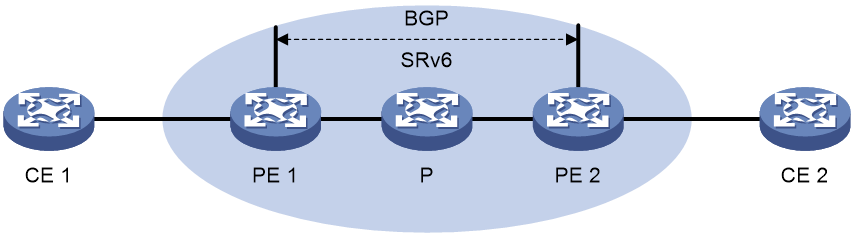
Public network IP over SRv6 uses SRv6 tunnels to carry public network IP services. This technology establishes SRv6 tunnels among geographically dispersed customer sites over an IPv6 network and transparently forwards Layer 3 customer traffic to remote sites over the IPv6 network through the tunnels.
Basic principle
Figure 1 shows a typical public network IP over SRv6 network. PE 1 and PE 2 use BGP to advertise public network IPv6 routes to each other over the IPv6 backbone network. The PEs use an SRv6 tunnel between them to forward public network traffic across sites.
Public network IP over SRv6 connects geographically dispersed sites that belong to the public network over the IPv6 backbone network.
Route advertisement
Public network IPv4 over SRv6 and public network IPv6 over SRv6 use the same process to advertise routes. The following information uses public network IPv4 over SRv6 as an example to illustrate the process.
As shown in the network diagram in "Basic principle," local routes of CE 1 are advertised to CE 2 by using the following process:
1. CE 1 uses static routing, RIP, OSPF, IS-IS, EBGP, or IBGP to advertise routes of the local site to PE 1.
2. After learning the route information of CE 1, PE 1 stores the routes of the local site to the routing table of the public network. At the same time, PE 1 converts the routes to BGP IPv4 unicast routes and adds an SID to each of the routes. Then, PE 1 advertises the BGP IPv4 unicast routes with the SID to PE 2.
¡ If next hop-based dynamic SID allocation is not enabled, all the public network routes are allocated the same End.DT4 or End.DT46 SID.
¡ If next hop-based dynamic SID allocation is enabled, public network routes with the same next hop are allocated the same End.DX4 SID.
3. When PE 2 receives the IPv4 unicast routes advertised by PE 1, it adds the routes to the routing table of the public network. PE 2 removes the End.DT4, End.DT46, or End.DX4 SID information from the routes, records the SID information, and then advertises the routes to CE 2.
4. By adding the received IPv4 unicast routes to the routing table, CE 2 learns the routes of CE 1.
Packet forwarding
Public network IP over SRv6 supports the following route recursion modes:
· SRv6 BE mode.
· SRv6 TE mode.
· SRv6 TE and SRv6 BE hybrid mode.
· SRv6 TE and SRv6 BE FRR mode.
The packet forwarding process differs by the route recursion mode in use.
SRv6 BE mode
This mode is also called SID-based forwarding mode. In this mode, a PE forwards an SRv6 packet by searching the IPv6 routing table based on the SRv6 SID encapsulated in the packet.
Public network IPv4 over SRv6 and public network IPv6 over SRv6 use the same process to forward packets. The following information uses public network IPv4 over SRv6 as an example to illustrate the process.
As shown in Figure 1, CE 2 forwards an IPv4 packet to CE 1 as follows:
1. CE 2 sends the IPv4 packet to PE 2.
2. After PE 2 receives the packet, it searches for a route that matches the destination IPv4 address of the packet in the routing table of the public network. The corresponding End.DT4, End.DT46, or End.DX4 SID is found. Then, PE 2 encapsulates an outer IPv6 header for the packet. The End.DT4, End.DT46, or End.DX4 SID is encapsulated in the outer IPv6 header as the destination address.
3. PE 2 searches the IPv6 routing table based on the End.DT4, End.DT46, or End.DX4 SID for the optimal IGP route and forwards the packet to P through the route.
4. P searches the IPv6 routing table based on the End.DT4, End.DT46, or End.DX4 SID for the optimal IGP route and forwards the packet to PE 1 through the route.
5. When PE 1 receives the packet, it processes the packet as follows:
¡ If the packet header contains an End.DT4 or End.DT46 SID, PE 1 searches the local SID forwarding table for the SID and removes the outer IPv6 header. Then, PE 1 matches the packet to the public instance based on the SID, looks up the public network routing table, and forwards the packet to CE 1.
¡ If the packet header contains an End.DX4 SID, PE 1 searches the local SID forwarding table for the SID and removes the outer IPv6 header. Then, PE 1 forwards the packet to CE 1 according to the next hop and output interface bound to the SID.
SRv6 TE mode
This mode is also called SRv6 TE policy-based forwarding mode. In this mode, when a PE forwards a customer packet, it first searches for a matching SRv6 TE policy based on the packet attributes. Then, the PE adds an SRH to the packet. The SRH includes the destination SRv6 SID and the SID list of the SRv6 TE policy. Finally, the PE forwards the encapsulated packet based on the SRv6 TE policy.
The following modes are available to steer traffic to an SRv6 TE policy:
· Color—The device searches for an SRv6 TE policy that has the same color and endpoint address as the color and nexthop address of a BGP route. If a matching SRv6 TE policy exists, the device recurses the BGP route to that SRv6 TE policy. When the device receives packets that match the BGP route, it forwards the packets through the SRv6 TE policy.
· Tunnel policy—The device searches the tunnel policies for a matching SRv6 TE policy based on the next hop of a matching route. Configure a preferred tunnel or load sharing tunnel policy that uses the SRv6 TE policy. In this way, the SRv6 TE policy will be used as the public tunnel to carry the SRv6 PW that forwards packets.
For more information about tunnel policies, see MPLS Configuration Guide. For more information about SRv6 TE policies, see "Configuring SRv6 TE policies."
SRv6 TE and SRv6 BE FRR mode
In SRv6 TE and SRv6 BE FRR mode, FRR is formed by the paths selected in SRv6 TE mode and SRv6 BE mode. The primary path is the selected in SRv6 TE mode. If no available SRv6 TE policy is found in SRv6 TE mode, traffic is immediately switched over to the backup SRv6 BE path for forwarding. The SRv6 TE and SRv6 BE FRR mode reduces the path re-convergence time after recursion mode switchover to implement fast protection and avoid traffic loss for a long time.
SRv6 multi-level FRR (primary SRv6 TE path -> backup SRv6 TE path -> primary SRv6 BE path -> backup SRv6 BE path)
Multi-level FRR is formed by SRv6 TE and SRv6 BE paths. The primary paths contain one primary SRv6 TE path and one backup SRv6 TE path. The backup paths contain one primary SRv6 BE path and one backup SRv6 BE path. The device selects a forwarding path in the sequence: primary SRv6 TE path -> backup SRv6 TE path -> primary SRv6 BE path -> backup SRv6 BE path. Multiple SRv6 TE and SRv6 BE paths form multi-level FRR to implement fast protection and avoid traffic loss for a long time.
SRv6 multi-level FRR (primary SRv6 TE path -> primary SRv6 BE path -> backup SRv6 TE path -> backup SRv6 BE path)
Multi-level FRR is formed by SRv6 TE and SRv6 BE paths. The primary paths contain one primary SRv6 TE path and one primary SRv6 BE path. The backup paths contain one backup SRv6 TE path and one backup SRv6 BE path. The device selects a forwarding path in the sequence: primary SRv6 TE path -> primary SRv6 BE path -> backup SRv6 TE path -> backup SRv6 BE path. Multiple SRv6 TE and SRv6 BE paths form multi-level FRR to implement fast protection and avoid traffic loss for a long time.
Public network IP over SRv6 FRR
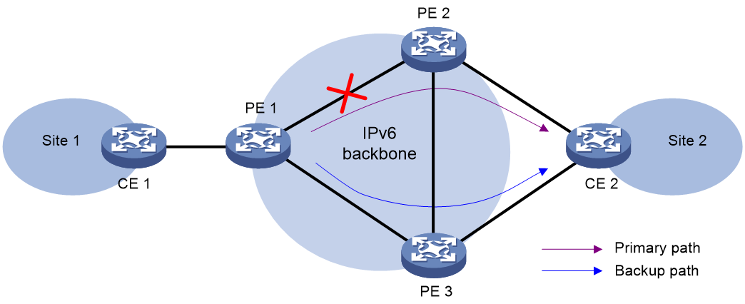
Public network IP over SRv6 Fast Reroute (FRR) is applicable to a dualhomed scenario, as shown in Figure 2. By using static BFD to detect the primary link, FRR enables a PE to use the backup link when the primary link fails. The PE then selects a new optimal route, and uses the new optimal route to forward traffic.
Public network IP over SRv6 supports IPv4 unicast route backup for IPv4 unicast route and IPv6 unicast route backup for IPv6 unicast route.
Figure 2 Network diagram of public network IP over SRv6 FRR
IPv4 unicast route backup for IPv4 unicast route and IPv6 unicast route backup for IPv6 unicast route use the same FRR mechanism. This section uses IPv4 unicast route backup for IPv4 unicast route as an example to illustrate the mechanism.
As shown in Figure 2, configure FRR on the ingress node PE 1, and specify the backup next hop as PE 3 for the public IPv4 route to CE 2. When PE 1 receives a BGP IPv4 unicast route to CE 2 from both PE 2 and PE 3, it uses the route from PE 2 as the primary path, and the route from PE 3 as the backup path.
Configure static BFD for public tunnels on PE 1 to detect the connectivity of the public tunnel from PE 1 to PE 2. When the tunnel PE 1—PE 2 operates correctly, traffic from CE 1 to CE 2 goes through the path CE 1—PE 1—PE 2—CE 2. When the tunnel fails, the traffic goes through the path CE 1—PE 1—PE 3—CE 2.
In this scenario, PE 1 is responsible for primary path detection and traffic switchover.
For more information about static BFD, see BFD configuration in High Availability Configuration Guide.
Restrictions and guidelines: Public network IP over SRv6 configuration
In the public network IP over SRv6 network scenario, the following settings do not take effect for routes received from public network peers:
· Import routing policy configured with the import route-policy command in public network instance view, public network instance IPv4 address family view, or public network instance IPv6 address family view.
· Export routing policy configured with the export route-policy command in public network instance view, public network instance IPv4 address family view, or public network instance IPv6 address family view.
In a scenario where BGP routes are imported between the public network and a VPN instance, you can configure the import route-policy and export route-policy commands to deploy routing policies. For more information about importing BGP routes between the public network and a VPN instance, see MPLS L3VPN configuration in MPLS Configuration Guide.
Public network IP over SRv6 tasks at a glance
To configure public network IP over SRv6, perform the following tasks:
1. Configuring route exchange between a PE and a CE
Configure an IPv4 routing protocol (static routing, RIP, OSPF, IS-IS, EBGP, or IBGP) or an IPv6 routing protocol (IPv6 static routing, RIPng, OSPFv3, IPv6 IS-IS, EBGP, or IBGP) to exchange routes between a PE and a CE
On the CE, configure an IPv4 or IPv6 routing protocol to advertise routes of the local site to the PE. For more information about routing protocol configurations, see Layer 3—IP Routing Configuration Guide.
2. Configuring route exchange between PEs
Perform this task to manually configure an End.DT4, End.DT6, End.DT46, End.DX4, or End.DX6 SID.
b. Applying a locator to a BGP instance
Perform this task to use BGP IPv4 or IPv6 unicast routes to advertise SRv6 SIDs in the specified locator.
c. Configuring PEs to exchange BGP IPv4 or IPv6 unicast routes
d. Configuring IPv6 peers to exchange SRv6 SIDs
This feature enables PEs to exchange End.DT4, End.DT6, End.DT46, End.DX4, or End.DX6 SIDs through BGP IPv4 or IPv6 unicast routes.
e. (Optional.) Configuring next hop-based dynamic End.DX4 or End.DX6 SID allocation for public network routes
f. (Optional.) Configuring BGP IPv4 or IPv6 unicast routes
For more information about configuring BGP IPv4 or IPv6 unicast routes, see BGP configuration in Layer 3—IP Routing Configuration Guide.
3. Configuring the route recursion mode
4. Specifying a source address for the outer IPv6 header of SRv6-encapsulated packets
This feature specifies the source address of the outer IPv6 header for SRv6 packets that are delivered between two public network sites over the backbone network.
5. (Optional.) Configuring public network IP over SRv6 FRR
6. (Optional.) Configuring SBFD for SRv6 locators
Configuring an SRv6 SID
Configuring a common SRv6 SID
1. Enter system view.
system-view
2. Enable SRv6 and enter SRv6 view.
segment-routing ipv6
3. Configure a locator and enter SRv6 locator view.
locator locator-name [ ipv6-prefix ipv6-address prefix-length [ args args-length | static static-length ] * ]
4. Configure an opcode. Perform one of the following tasks:
¡ Configure an End.DT4 SID.
opcode { opcode | hex hex-opcode } end-dt4
¡ Configure an End.DT6 SID.
opcode { opcode | hex hex-opcode } end-dt6
¡ Configure an End.DT46 SID.
opcode { opcode | hex hex-opcode } end-dt46
¡ Configure an End.DX4 SID.
opcode { opcode | hex hex-opcode } end-dx4 interface interface-type interface-number nexthop nexthop-ipv4-address
An End.DX4 SID cannot be configured with different output interfaces or next hops.
¡ Configure an End.DX6 SID.
opcode { opcode | hex hex-opcode } end-dx6 interface interface-type interface-number nexthop nexthop-ipv6-address
An End.DX6 SID cannot be configured with different output interfaces or next hops.
Configuring SRv6 SIDs for a COC16-type locator
About this task
A locator specified with the compress-16 keyword is a COC16-type locator. Such locators are used for assigning SIDs in the 16-bit G-SRv6 scenario. COC16 locators can be divided into the following types:
· Default-mode locator—A locator without the next keyword specified. You can assign a G-SID with the COC flavor, NEXT flavor, and COC&NEXT flavor, or a common SID without COC or NEXT flavors. This locator applies to all 16-bit compression G-SRv6 encapsulation solutions.
· Next-mode locator—A locator with the next keyword specified. Use this feature to assign a G-SID that carries only the NEXT flavor, or a common SID that does not carry the COC or NEXT flavor. When the H3C device interoperates with a third-party device that supports the 16-bit compression G-SRv6 encapsulation solution with only the move action, configure a Next-mode locator to allocate SIDs.
· Wlib-mode locator—A locator with the next-wlib keyword specified. It can allocate G-SIDs with the NEXT flavor from the extended W-LIB space or from the compressed function. In the current software version, the Wlib-mode locator typically uses the W-LIB space to allocate SIDs for VPN services.
Restrictions and guidelines
For a Wlib-mode locator, to allocate an opcode from the W-LIB space, follow these guidelines when you execute the opcode command to configure VPN-related SIDs such as End.DT4 SIDs: 1. First, make sure the specified opcode or hexadecimal hex-opcode includes one of the values in the range of wlib-static-value to wlib-start-value+7 specified in the locator command. 2. Then, specify the opcode in the W-LIB space. As a best practice, use the hexadecimal hex-opcode argument to configure the opcode. For example, if the value for the wlib-start-value argument is 0xFFF3 and the value for the wlib-static-value argument is 0xFFF7, you must first specify a value between FFF7 and FFFA for the hex-opcode argument, and then then assign an opcode in the W-LIB space.
Configuring SRv6 SIDs for a default-mode locator
1. Enter system view.
system-view
2. Enable SRv6 and enter SRv6 view.
segment-routing ipv6
3. Enable SRv6 compression.
srv6 compress enable
By default, SRv6 compression is disabled.
4. Configure a default-mode locator and enter SRv6 locator view.
locator locator-name [ ipv6-prefix ipv6-address prefix-length compress-16 [ non-compress-static non-compress-static-length ] [ args args-length | static static-length ] * ]
5. Configure an opcode to statically specify an SRv6 SID and the SID-associated function and flavor.
¡ Assign a common SRv6 SID that does not carry the COC or NEXT flavor from the non-compressed Function portion. (Details not shown.)
¡ Assign an SRv6 SID that carries the COC or NEXT flavor from the compressed Function portion.
opcode { opcode | hex hex-opcode } end-dt4 compress { next | coc-next }
Configure an End.DT4 SID.
opcode { opcode | hex hex-opcode } end-dt46 compress { next | coc-next }
Configure an End.DT46 SID.
opcode { opcode | hex hex-opcode } end-dt6 compress { next | coc-next }
Configure an End.DT6 SID.
opcode { opcode | hex hex-opcode } end-dx4 interface interface-type interface-number nexthop nexthop-ipv4-address compress { next | coc-next }
Configure an End.DX4 SID.
opcode { opcode | hex hex-opcode } end-dx6 interface interface-type interface-number nexthop nexthop-ipv4-address compress { next | coc-next }
Configure an End.DX6 SID.
Configuring SRv6 SIDs for a Next-mode locator
1. Enter system view.
system-view
2. Enable SRv6 and enter SRv6 view.
segment-routing ipv6
3. Enable SRv6 compression.
srv6 compress enable
By default, SRv6 compression is disabled.
4. Configure a Next-mode locator and enter SRv6 locator view.
locator locator-name [ ipv6-prefix ipv6-address prefix-length compress-16 next [ non-compress-static non-compress-static-length ] [ args args-length | static static-length ] * ]
5. Configure an opcode to statically specify an SRv6 SID and the SID-associated function and flavor.
¡ Assign a common SRv6 SID that does not carry the COC or NEXT flavor from the non-compressed Function portion. (Details not shown.)
¡ Assign an SRv6 SID that carries the NEXT flavor from the compressed Function portion.
opcode { opcode | hex hex-opcode } end-dt4 compress next
Configure an End.DT4 SID.
opcode { opcode | hex hex-opcode } end-dt46 compress next
Configure an End.DT46 SID.
opcode { opcode | hex hex-opcode } end-dt6 compress next
Configure an End.DT6 SID.
opcode { opcode | hex hex-opcode } end-dx4 interface interface-type interface-number nexthop nexthop-ipv4-address compress next
Configure an End.DX4 SID.
opcode { opcode | hex hex-opcode } end-dx6 interface interface-type interface-number nexthop nexthop-ipv4-address compress next
Configure an End.DX6 SID.
Configuring SRv6 SIDs for a Wlib-mode locator
1. Enter system view.
system-view
2. Enable SRv6 and enter SRv6 view.
segment-routing ipv6
3. Enable SRv6 compression.
srv6 compress enable
By default, SRv6 compression is disabled.
4. Configure a Wlib-mode locator and enter SRv6 locator view.
locator locator-name [ ipv6-prefix ipv6-address prefix-length compress-16 next-wlib [ wlib-start wlib-start-value ] [ wlib-static-start wlib-static-value ] [ args args-length | static static-length ] * ]
5. Configure an opcode to statically specify an SRv6 SID and the SID-associated function and flavor.
¡ Assign an SRv6 SID that carries the NEXT flavor from the extended W-LIB space.
opcode { opcode | hex hex-opcode } end-dt4 compress next
Configure an End.DT4 SID.
opcode { opcode | hex hex-opcode } end-dt46 compress next
Configure an End.DT46 SID.
opcode { opcode | hex hex-opcode } end-dt6 compress next
Configure an End.DT6 SID.
opcode { opcode | hex hex-opcode } end-dx4 interface interface-type interface-number nexthop nexthop-ipv4-address compress next
Configure an End.DX4 SID.
opcode { opcode | hex hex-opcode } end-dx6 interface interface-type interface-number nexthop nexthop-ipv4-address compress next
Configure an End.DX6 SID.
Applying a locator to a BGP instance
About this task
In the public network IP over SRv6 scenario, use this feature in BGP IPv4 or IPv6 unicast address family view to apply for SRv6 SIDs for IPv4 or IPv6 routes.
Use this feature if the device will use End.DT4, End.DT6, End.DT46, End.DX4, or End.DX6 SIDs to deliver public network traffic across sites.
In the 16-bit compression G-SRv6 scenario, use this feature to specify a locator of the COC16 type and specify the compress-16 keyword. This allows allocation of VPN SIDs such as End.DT4, End.DT6, End.DT46, End.DX4, and End.DX6 SIDs from that locator, which carry the COC&NEXT or NEXT flavor. When encapsulating SRv6 packets, the source node can compress the previous VPN SIDs to 16 bits before encapsulating them into the SRv6 packets, reducing the length of the SRv6 packet header. Upon receiving a 16-bit compressed G-SRv6 packet, the PE acting as the endpoint node of the SRv6 tunnel performs the replace or move action operation based on the COC or NEXT flavor carried by the VPN SID. For more information about the replace and move actions, see SRv6 configuration in Segment Routing Configuration Guide.
Restrictions and guidelines
Before you perform this task, you must create the specified locator.
If you execute the segment-routing ipv6 locator command and specify the compress-16 keyword, you must specify the COC16-type locator for this command. Without this configuration, SID allocation from the locator might not be as expected.
· If you execute the segment-routing ipv6 locator command to specify a non-COC16-type locator, specifying the compress-16 keyword will not take effect. That is, you cannot allocate SIDs from that locator.
· If you execute the segment-routing ipv6 locator command to specify a COC16-type locator in default or Next mode, and do not specify the compress-16 keyword, common SIDs can be allocated from the non-compressed Function portion of that locator. Common SIDs do not carry the COC or NEXT flavor.
· If you execute the segment-routing ipv6 locator command to specify a COC16-type locator in Wlib mode, and do not specify the compress-16 keyword, SIDs cannot be allocated from that locator.
If you execute the segment-routing ipv6 locator command and specify the compress-16 keyword, you can also execute the segment-routing ipv6 apply-sid compress command to configure the flavor for the SIDs allocated from the locator.
Procedure
1. Enter system view.
system-view
2. Enter BGP instance view.
bgp as-number [ instance instance-name ]
3. Enter BGP IPv4 or IPv6 unicast address family view.
¡ Enter BGP IPv4 unicast address family view.
address-family ipv4 [ unicast ]
¡ Enter BGP IPv6 unicast address family view.
address-family ipv6 [ unicast ]
4. Apply a locator to the BGP instance.
segment-routing ipv6 locator locator-name [ auto-sid-disable | auto-sid-dt46 ] [ compress-16 ]
By default, no locator is applied to a BGP instance.
5. (Optional) Configure the flavor carried in the SIDs dynamically allocated from the COC16-type locator specified for BGP.
segment-routing ipv6 apply-sid compress { coc-next | next [ wlib ] } [ end-dt46 ]
By default, for a COC16-type locator in default mode, SRv6 SIDs are allocated with the COC and NEXT flavors from the compressed Function portion. For a COC16-type locator in Next mode, SRv6 SIDs are allocated with the NEXT flavor from the compressed Function portion. For a COC16-type locator in Wlib mode, SRv6 SIDs are allocated with the NEXT flavor from the W-LIB space.
Configuring PEs to exchange BGP IPv4 or IPv6 unicast routes
Restrictions and guidelines
For more information about the commands in this task, see BGP in Layer 3—IP Routing Command Reference.
To ensure optimal route selection and SRv6 tunnel traffic forwarding, make sure a pair of PEs are not both IPv4 and IPv6 peers to each other.
Procedure
1. Enter system view.
system-view
2. Enter BGP instance view.
bgp as-number [ instance instance-name ]
3. Specify a remote PE as an IPv6 peer.
peer { group-name | ipv6-address [ prefix-length ] } as-number as-number
4. Specify a source interface (IPv6 address) for establishing TCP connections to an IPv6 peer or peer group.
peer { group-name | ipv6-address [ prefix-length ] } connect-interface interface-type interface-number
By default, BGP uses the output interface in the optimal route destined for a BGP peer or peer group as the source interface for establishing TCP connections.
5. Enter BGP IPv4 or IPv6 unicast address family view.
¡ Enter BGP IPv4 unicast address family view.
address-family ipv4 [ unicast ]
¡ Enter BGP IPv6 unicast address family view.
address-family ipv6 [ unicast ]
6. Enable BGP to exchange IPv4 or IPv6 unicast routing information with an IPv6 peer or peer group.
peer { group-name | ipv6-address [ prefix-length ] } enable
By default, BGP cannot exchange IPv4 or IPv6 unicast routing information with an IPv6 peer or peer group.
Configuring IPv6 peers to exchange SRv6 SIDs
About this task
Perform this task to configure IPv6 peers to exchange SRv6 SID information through BGP IPv4 or IPv6 unicast routes.
Procedure
1. Enter system view.
system-view
2. Enter BGP instance view.
bgp as-number [ instance instance-name ]
3. Enter BGP IPv4 or IPv6 unicast address family view.
¡ Enter BGP IPv4 unicast address family view.
address-family ipv4 [ unicast ]
¡ Enter BGP IPv6 unicast address family view.
address-family ipv6 [ unicast ]
4. Enable BGP to exchange SRv6 SID information with an IPv6 peer or peer group.
peer { group-name | ipv6-address [ prefix-length ] } prefix-sid
By default, BGP cannot exchange SRv6 SID information with an IPv6 peer or peer group.
Configuring next hop-based dynamic End.DX4 or End.DX6 SID allocation for public network routes
About this task
This feature is applicable to the public network IPv6 over SRv6 scenario.
By default, a PE allocates the same SID to all BGP public network routes. When the PE removes the SRv6 encapsulation from a received packet, it looks up the routing table of the public network based on the SID for an optimal route. To forward the packet to the next hop without looking up the routing table, configure this feature.
This feature dynamically allocates End.DX4 or End.DX6 SIDs to all next hops for the BGP public network IPv4 or IPv6 routes. When forwarding a packet, the PE searches for the output interface and next hop based on the End.DX4 or End.DX6 SID of the packet. Then, the PE directly forwards the packet out of the output interface to the next hop.
Restrictions and guidelines
This feature does not allocate End.DX4 or End.DX6 SIDs to direct routes.
Prerequisites
Before you perform this task in BGP IPv4 or IPv6 unicast address family view, execute the segment-routing ipv6 locator command in the same view to apply a locator to the view. This ensures successful dynamic End.DX4 or End.DX6 SID allocation.
Procedure
1. Enter system view.
system-view
2. Enter BGP instance view.
bgp as-number [ instance instance-name ]
3. Enter BGP IPv4 unicast address family view or BGP IPv6 unicast address family view.
¡ Enter BGP IPv4 unicast address family view.
address-family ipv4 [ unicast ]
¡ Enter BGP IPv6 unicast address family view.
address-family ipv6 [ unicast ]
4. Allocate End.DX4 or End.DX6 SIDs to the next hops of BGP public network routes.
¡ Allocate End.DX4 or End.DX6 SIDs to all next hops of BGP public network routes.
segment-routing ipv6 apply-sid all-nexthop
¡ Execute the following commands in sequence to allocate End.DX4 or End.DX6 SIDs to the specified next hop of BGP public network routes.
segment-routing ipv6 apply-sid specify-nexthop
nexthop nexthop-address interface interface-type interface-number
By default, public instance-based SID allocation is used for public network routes.
Configuring the route recursion mode
About this task
After a PE receives a customer packet destined for an SRv6 SID, it forwards the packet according to the route recursion mode.
· SRv6 BE mode—This mode is also called SID-based forwarding mode. In this mode, the PE first encapsulates the End.DT4, End.DT6, or End.DT46 SID into the packet. Then, the PE searches the IPv6 routing table based on the SID encapsulated in the packet to forward the packet.
· SRv6 TE mode—This mode is also called SRv6 TE policy-based forwarding mode. In this mode, the PE first searches for a matching SRv6 TE policy based on the packet attributes. Then, the PE adds an SRH to the packet. The SRH includes the End.DT4, End.DT6, or End.DT46 SID and the SID list of the SRv6 TE policy. Finally, the PE forwards the encapsulated packet through the SRv6 TE policy. For more information, see "Configuring SRv6 TE policies."
· SRv6 TE and SRv6 BE FRR mode—To use this mode, specify the best-effort keyword for the command. This mode implements FRR by using the SRv6 TE path (primary path) and SRv6 BE path (backup path). If the SRv6 TE path fails or does not exist, traffic is immediately switched to the SRv6 BE path to ensure service continuity.
· Multi-level FRR is formed by SRv6 TE and SRv6 BE paths.
¡ Specify the best-effort keyword but do not specify the local-preference keyword for the command to form multi-level FRR with SRv6 TE and SRv6 BE paths. The primary paths contain one primary SRv6 TE path and one backup SRv6 TE path. The backup paths contain one primary SRv6 BE path and one backup SRv6 BE path. The device selects a forwarding path in the sequence: primary SRv6 TE path -> backup SRv6 TE path -> primary SRv6 BE path -> backup SRv6 BE path. Multiple SRv6 TE and SRv6 BE paths form multi-level FRR to implement fast protection and avoid traffic loss for a long time. This keyword applies to dualhomed scenarios.
¡ Specify both the best-effort and local-preference keywords for the command to form multi-level FRR with SRv6 TE and SRv6 BE paths. The primary paths contain one primary SRv6 TE path and one primary SRv6 BE path. The backup paths contain one backup SRv6 TE path and one backup SRv6 BE path. The device selects a forwarding path in the sequence: primary SRv6 TE path -> primary SRv6 BE path -> backup SRv6 TE path -> backup SRv6 BE path. Multiple SRv6 TE and SRv6 BE paths form multi-level FRR to implement fast protection and avoid traffic loss for a long time. This keyword applies to dualhomed scenarios.
When the route recursion mode is SRv6 BE, SRv6 TE and SRv6 BE FRR, or SRv6 TE and SRv6 BE multilevel FRR, if the locator associated with the SIDs assigned by BGP to routes matches multiple IGP network routes (that is, the IGP-advertised locator route has multiple next hops), the BGP route can recurse to multiple SRv6 BE paths. If multiple IGP routes matching the locator form FRR, the multiple SRv6 BE paths obtained through recursion for the BGP route also form the same type of FRR. The rules to form FRR vary by IGP. For more information, see the associated IGP configuration guide.
Procedure
1. Enter system view.
system-view
2. Enter BGP instance view.
bgp as-number [ instance instance-name ]
3. Enter BGP IPv4 or IPv6 unicast address family view.
¡ Enter BGP IPv4 unicast address family view.
address-family ipv4 [ unicast ]
¡ Enter BGP IPv6 unicast address family view.
address-family ipv6 [ unicast ]
4. Configure the route recursion mode.
segment-routing ipv6 { best-effort | traffic-engineering | traffic-engineering best-effort [ local-preference ] }
By default, a PE searches the IPv6 routing table based on the next hop of a matching route to forward traffic.
Specifying a source address for the outer IPv6 header of SRv6-encapsulated packets
Restrictions and guidelines
To ensure correct traffic forwarding in the public network IPv6 over SRv6 scenario, you must specify a source address for the outer IPv6 header of SRv6-encapsulated packets.
You cannot specify a loopback address, link-local address, multicast address, or unspecified address as the source IPv6 address. You must specify an IPv6 address of the local device as the source IPv6 address, and make sure the IPv6 address has been advertised by a routing protocol. As a best practice, specify a loopback interface address of the local device as the source IPv6 address.
Procedure
1. Enter system view.
system-view
2. Enter SRv6 view.
segment-routing ipv6
3. Specify a source address for the outer IPv6 header of SRv6-encapsulated packets.
encapsulation source-address ipv6-address [ ip-ttl ttl-value ]
By default, no source address is specified for the outer IPv6 header of SRv6-encapsulated packets.
Configuring public network IP over SRv6 FRR
About this task
You can enable public network IP over SRv6 FRR by enabling FRR for a specific public network address family. Public network IP over SRv6 FRR enables the device to calculate backup routes for all BGP routes of the address family. If the device learns two unequal-cost routes destined for the same network from different peers, the optimal route is backed up by the other route. When the optimal route becomes unavailable, the device uses the backup route to forward traffic. At the same time, the device calculates a new optimal route and then uses it to direct traffic forwarding.
By default, the public instance IP routing table does not have SRv6 SID route information. As a result, FRR can only use the static BFD session for the locator network address to detect the primary path between PEs. If multiple address families of the public instance have used the same locator, FRR in these address families might use the same static BFD session to detect the primary path. Once the BFD session detects that the path is not available, the BGP routes in all these address families will perform path switching simultaneously.
For refined FRR management, the segment-routing ipv6 primary-path-detect sid-bfd command is provided in BGP IPv4 unicast address family view and BGP IPv6 unicast address family view. After this command is executed, when the device adds a BGP IPv4/IPv6 unicast route that contains an SRv6 SID to the public instance IP routing table, it adds the SRv6 SID as the next hop of the route. This allows FRR to automatically and preferentially associate the static BFD session for the SRv6 SID to detect the primary path. Once BFD detects that an SRv6 SID is not reachable, it triggers the BGP routes in only one address family to perform path switching. This mechanism provides a smaller control granularity for FRR.
Restrictions and guidelines
This feature might cause routing loops in certain conditions. Make sure you are fully aware of this feature when you use it on a live network.
The segment-routing ipv6 primary-path-detect sid-bfd command applies only to routes that use the SRv6 BE route recursion mode. If the route recursion mode is SRv6 TE and SRv6 BE hybrid, SRv6 TE and SRv6 BE FRR, or SRv6 TE and SRv6 BE multilevel FRR, this command takes effect only when the SRv6 TE path is not available.
Procedure
1. Enter system view.
system-view
2. Configure static BFD.
bfd static session-name [ peer-ipv6 ipv6-address [ vpn-instance vpn-instance-name ] source-ipv6 ipv6-address [ discriminator local local-value remote remote-value ] [ track-interface interface-type interface-number ] ]
If the segment-routing ipv6 primary-path-detect sid-bfd command is not executed, the addresses specified by the peer-ipv6 ipv6-address option and source-ipv6 ipv6-address option must be the locator subnet addresses advertised by the two peers of the link.
If the segment-routing ipv6 primary-path-detect sid-bfd command is executed, the addresses specified by the peer-ipv6 ipv6-address option and source-ipv6 ipv6-address option can be the SRv6 SIDs assigned by the two peers of the link in the public instance.
3. Return to system view.
quit
4. Enter BGP instance view.
bgp as-number [ instance instance-name ]
5. Configure BGP FRR to use the control packet or echo packet mode BFD to detect next hop connectivity for the primary route.
primary-path-detect bfd { ctrl | echo }
By default, BGP FRR uses ARP to detect the connectivity to the next hop of the primary route.
For more information about this command, see BGP commands in Layer 3—IP Routing Command Reference.
6. (Optional.) Enable using the static BFD session for the SRv6 SID to detect the reachability of the primary path for FRR.
¡ Enable this feature in BGP IPv4 unicast address family view:
address-family ipv4 [ unicast ]
segment-routing ipv6 primary-path-detect sid-bfd
¡ Enable this feature in BGP IPv6 unicast address family view:
address-family ipv6 [ unicast ]
segment-routing ipv6 primary-path-detect sid-bfd
By default, the device detects the reachability of the FRR primary path by using the static BFD session for the locator.
7. Enable FRR for the address family.
pic
By default, FRR is disabled for a BGP address family.
For more information about this command, see BGP commands in Layer 3—IP Routing Command Reference.
Configuring SBFD for SRv6 locators
About this task
As shown in Figure 3, in the public network IP over SRv6 BE scenario, CE 2 is dual homed to PE 2 and PE 3. After you enable FRR on PE 1, a primary path and a backup path are generated on PE 1. When the primary path fails, you can configure this feature for fast traffic switchover to the backup path. Use SBFD to detect connectivity of the SRv6 locator (next hop address obtained through route recursion for the private network route) advertised by PE 2 to fast locate primary path failures and switch traffic over to the backup path.
Figure 3 Using SBFD to detect SRv6 locators in a dual-homed network
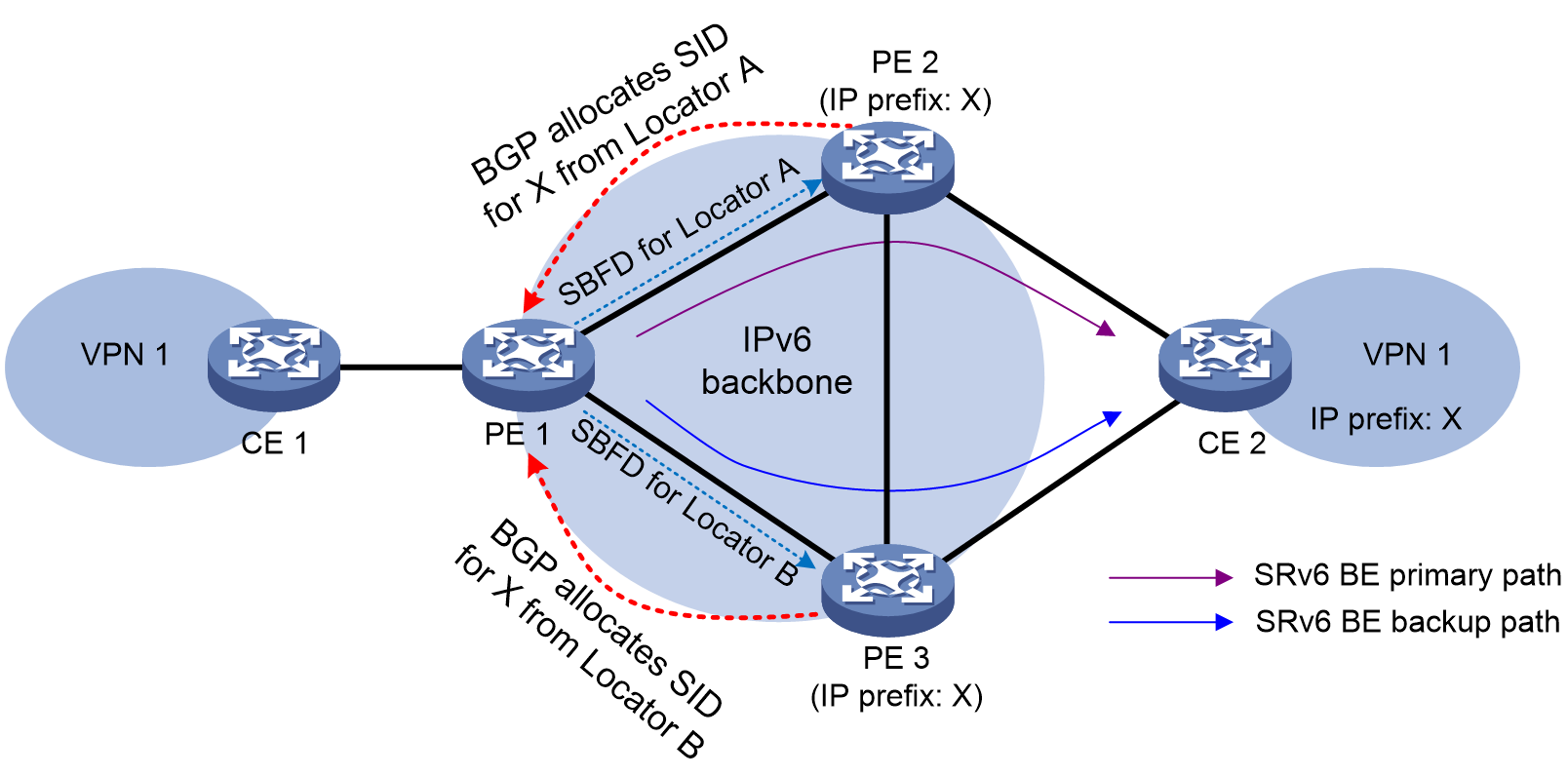
SBFD detects the connectivity of SRv6 locators as follows:
1. PE 1 sends SBFD packets as the initiator. The SRv6 locators are the destination addresses of the SBFD packets. The IP address specified in the sbfd source-ipv6 command is used as the source IP address of SBFD packets.
2. When PE 2 and PE 3 receive the SBFD packets as reflectors, they compare the remote discriminators in the packets with the locally configured discriminators.
¡ If they are consistent, the reflectors send SBFD response packets to the initiator through IPv6 routes.
¡ If they are inconsistent, the reflectors drop the received SBFD packets.
3. If the initiator can receive SBFD response packets before the detection timer expires, it determines that the SRv6 locators are reachable. If not, the initiator determines that the SRv6 locators are unreachable, and switches over to the backup path.
Restrictions and guidelines
To have this feature take effect, execute the sbfd destination ipv6 remote-discriminator command on PE 1 to configure the mappings between the detected SRv6 locators and remote discriminators. In addition, execute the sbfd local-discriminator command on PE 2 and PE 3 to configure the local discriminators on the reflector end. Make sure PE 1 have consistent discriminator settings with PE 2 and PE 3. For more information about the sbfd destination ipv6 remote-discriminator and sbfd local-discriminator commands, see BFD commands in High Availability Command Reference.
Procedure
1. Enter system view.
system-view
2. Enter SRv6 view.
segment-routing ipv6
3. Configure SBFD for SRv6 locators.
locator-sbfd enable [ template template-name ] [ prefix-list prefix-list-name ]
By default, SBFD is not configured for SRv6 locators.
Display and maintenance commands for public network IP over SRv6
Resetting BGP sessions
For BGP setting changes to take effect, you must reset BGP sessions. Resetting BGP sessions updates BGP routing information by tearing down and re-establishing the BGP sessions.
Execute the command in this section in user view. For more information about the command, see BGP in Layer 3—IP Routing Command Reference.
|
Task |
Command |
|
Reset BGP sessions of the BGP IPv6 unicast address family. |
reset bgp [ instance instance-name ] { as-number | ipv6-address [ prefix-length ] | all | external | group group-name | internal } ipv6 [ unicast ] |
Displaying and maintaining the running status of public network IP over SRv6
Execute display commands in any view and reset commands in user view.
For more information about the commands in this section, see BGP in Layer 3—IP Routing Command Reference.
|
Task |
Command |
|
Display BGP IPv6 unicast route information. |
display bgp [ instance instance-name ] routing-table ipv6 [ unicast ] [ ipv6-address prefix-length [ advertise-info ] | as-path-acl as-path-acl-number | community-list { { basic-community-list-number | comm-list-name } [ whole-match ] | adv-community-list-number } | peer ipv6-address { advertised-routes | received-routes } [ ipv6-address prefix-length | statistics ] | statistics ] |
|
Clear flap statistics for BGP IPv6 unicast routes. |
reset bgp [ instance instance-name ] flap-info ipv6 [ unicast ] [ ipv6-address prefix-length | as-path-acl as-path-acl-number | peer ipv6-address [ prefix-length ] ] |
Public network IP over SRv6 configuration examples
Example: Configuring public network IPv6 over SRv6 in SRv6 BE mode
Network configuration
As shown in Figure 4, the backbone network is an IPv6 network. Deploy public network IPv6 over SRv6 between PE 1 and PE 2 and use an SRv6 tunnel to transmit IPv4 traffic between the PEs.
· Configure EBGP to exchange public network routing information between the CEs and PEs.
· Configure IPv6 IS-IS on the PEs in the same AS to realize IPv6 network connectivity.
· Configure IBGP to exchange IPv4 routing information between the PEs.
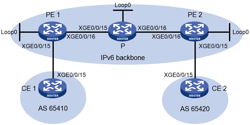
Table 1 Interface and IP address assignment
|
Device |
Interface |
IP address |
Device |
Interface |
IP address |
|
CE 1 |
XGE0/0/15 |
111::1/96 |
PE 2 |
Loop0 |
3::3/128 |
|
PE 1 |
Loop0 |
1::1/128 |
|
XGE0/0/15 |
222::2/96 |
|
|
XGE0/0/15 |
111::2/96 |
|
XGE0/0/16 |
2002::1/96 |
|
|
XGE0/0/16 |
2001::1/96 |
CE 2 |
XGE0/0/15 |
222::1/96 |
|
P |
Loop0 |
2::2/128 |
|
|
|
|
|
XGE0/0/15 |
2001::2/96 |
|
|
|
|
|
XGE0/0/16 |
2002::2/96 |
|
|
|
Prerequisites
Configure IP addresses for the interfaces (including the Loopback interfaces), as shown in Figure 4.
Procedure
1. Configure IPv6 IS-IS on the PEs and device P for network connectivity between the devices:
# Configure PE 1.
<PE1> system-view
[PE1] isis 1
[PE1-isis-1] is-level level-1
[PE1-isis-1] cost-style wide
[PE1-isis-1] network-entity 10.1111.1111.1111.00
[PE1-isis-1] address-family ipv6 unicast
[PE1-isis-1-ipv6] quit
[PE1-isis-1] quit
[PE1] interface loopback 0
[PE1-LoopBack0] isis ipv6 enable 1
[PE1-LoopBack0] quit
[PE1] interface ten-gigabitethernet 0/0/16
[PE1-Ten-GigabitEthernet0/0/16] isis ipv6 enable
[PE1-Ten-GigabitEthernet0/0/16] quit
# Configure P.
<P> system-view
[P] isis
[P-isis-1] is-level level-1
[P-isis-1] cost-style wide
[P-isis-1] network-entity 10.2222.2222.2222.00
[P-isis-1] address-family ipv6 unicast
[P-isis-1-ipv6] quit
[P-isis-1] quit
[P] interface loopback 0
[P-LoopBack0] isis ipv6 enable
[P-LoopBack0] quit
[P] interface ten-gigabitethernet 0/0/15
[P-Ten-GigabitEthernet0/0/15] isis ipv6 enable
[P-Ten-GigabitEthernet0/0/15] quit
[P] interface ten-gigabitethernet 0/0/16
[P-Ten-GigabitEthernet0/0/16] isis ipv6 enable
[P-Ten-GigabitEthernet0/0/16] quit
# Configure PE 2.
<PE2> system-view
[PE2] isis
[PE2-isis-1] is-level level-1
[PE2-isis-1] cost-style wide
[PE2-isis-1] network-entity 10.3333.3333.3333.00
[PE2-isis-1] address-family ipv6 unicast
[PE2-isis-1-ipv6] quit
[PE2-isis-1] quit
[PE2] interface loopback 0
[PE2-LoopBack0] isis ipv6 enable
[PE2-LoopBack0] quit
[PE2] interface ten-gigabitethernet 0/0/16
[PE2-Ten-GigabitEthernet0/0/16] isis ipv6 enable
[PE2-Ten-GigabitEthernet0/0/16] quit
2. Set up an EBGP peer relationship between each PE and its local CE and distribute CE routes to EBGP:
# Configure CE 1.
<CE1> system-view
[CE1] bgp 65410
[CE1-bgp-default] peer 111::2 as-number 100
[CE1-bgp-default] address-family ipv6 unicast
[CE1-bgp-default-ipv6] peer 111::2 enable
[CE1-bgp-default-ipv6] import-route direct
[CE1-bgp-default-ipv6] quit
[CE1-bgp-default] quit
# Configure CE 2 in the same way as CE 1 is configured. (Details not shown.)
# Configure PE 1.
[PE1] bgp 100
[PE1-bgp-default] router-id 1.1.1.1
[PE1-bgp-default] peer 111::1 as-number 65410
[PE1-bgp-default] address-family ipv6 unicast
[PE1-bgp-default-ipv6] peer 111::1 enable
[PE1-bgp-default-ipv6] import-route direct
[PE1-bgp-default-ipv6] quit
[PE1-bgp-default] quit
# Configure PE 2 in the same way PE 1 is configured. (Details not shown.)
3. Set up an IBGP peer relationship between PE 1 and PE 2:
# Configure PE 1.
[PE1] bgp 100
[PE1-bgp-default] peer 3::3 as-number 100
[PE1-bgp-default] peer 3::3 connect-interface loopback 0
[PE1-bgp-default] address-family ipv6 unicast
[PE1-bgp-default-ipv6] peer 3::3 enable
[PE1-bgp-default-ipv6] quit
[PE1-bgp-default] quit
# Configure PE 2.
[PE2] bgp 100
[PE2-bgp-default] peer 1::1 as-number 100
[PE2-bgp-default] peer 1::1 connect-interface loopback 0
[PE2-bgp-default] address-family ipv6 unicast
[PE2-bgp-default-ipv6] peer 1::1 enable
[PE2-bgp-default-ipv6] quit
[PE2-bgp-default] quit
4. Specify a source address for the outer IPv6 header of SRv6-encapsulated public network IP packets on PE 1 and PE 2:
# Configure PE 1.
[PE1] segment-routing ipv6
[PE1-segment-routing-ipv6] encapsulation source-address 1::1
# Configure PE 2.
[PE2] segment-routing ipv6
[PE2-segment-routing-ipv6] encapsulation source-address 3::3
5. Configure the destination address (End.DT6 SID) of the outer IPv6 header for SRv6-encapsulated public network IP packets:
# Configure PE 1.
[PE1-segment-routing-ipv6] locator aaa ipv6-prefix 1:2::1:0 96 static 8
[PE1-segment-routing-ipv6-locator-aaa] quit
[PE1-segment-routing-ipv6] quit
[PE1] isis 1
[PE1-isis-1] address-family ipv6 unicast
[PE1-isis-1-ipv6] segment-routing ipv6 locator aaa
[PE1-isis-1-ipv6] quit
[PE1-isis-1] quit
# Configure PE 2.
[PE2-segment-routing-ipv6] locator bbb ipv6-prefix 6:5::1:0 96 static 8
[PE2-segment-routing-ipv6-locator-bbb] quit
[PE2-segment-routing-ipv6] quit
[PE2] isis 1
[PE2-isis-1] address-family ipv6 unicast
[PE2-isis-1-ipv6] segment-routing ipv6 locator bbb
[PE2-isis-1-ipv6] quit
[PE2-isis-1] quit
6. Add End.DT6 SIDs to public network routes on PE 1 and PE 2:
# Configure PE 1.
[PE1] bgp 100
[PE1-bgp-default] address-family ipv6 unicast
[PE1-bgp-default-ipv6] segment-routing ipv6 locator aaa
[PE1-bgp-default-ipv6] quit
[PE1-bgp-default] quit
# Configure PE 2.
[PE2] bgp 100
[PE2-bgp-default] address-family ipv6 unicast
[PE2-bgp-default-ipv6] segment-routing ipv6 locator bbb
[PE2-bgp-default-ipv6] quit
[PE2-bgp-default] quit
7. Enable IPv6 peers on the PEs to exchange End.DT6 SIDs and enable SRv6 BE route recursion mode:
# Configure PE 1.
[PE1] bgp 100
[PE1-bgp-default] address-family ipv6 unicast
[PE1-bgp-default-ipv6] peer 3::3 prefix-sid
[PE1-bgp-default-ipv6] segment-routing ipv6 best-effort
[PE1-bgp-default-ipv6] quit
[PE1-bgp-default] quit
# Configure PE 2.
[PE2] bgp 100
[PE2-bgp-default] address-family ipv6 unicast
[PE2-bgp-default-ipv6] peer 1::1 prefix-sid
[PE2-bgp-default-ipv6] segment-routing ipv6 best-effort
[PE2-bgp-default-ipv6] quit
[PE2-bgp-default] quit
Verifying the configuration
# Display IPv6 routing table information on the PEs and verify that each PE has a route destined for the remote CE and the next hop of the route is the End.DT6 SID of the route. This step uses PE 1 as an example.
[PE1] display ipv6 routing-table 222::1 96
Summary count : 1
Destination: 222::/96 Protocol : BGP4+
NextHop : 6:5:: Preference: 255
Interface : XGE0/0/16 Cost : 0
# Verify that CE 1 and CE 2 can ping each other. (Details not shown.)
