- Table of Contents
-
- H3C WBC580 G2 Multiservice Access Controller Installation Guide-5W105
- 00-Preface
- 01-Preparing for installation
- 02-Installing and removing the device
- 03-Powering on, powering off, and rebooting the device
- 04-Logging in to the device
- 05-Maintenance
- 06-Appendix A Chassis views and technical specifications
- 07-Appendix B LEDs
- 08-Appendix C Optional transceiver modules
- Related Documents
-
| Title | Size | Download |
|---|---|---|
| 07-Appendix B LEDs | 233.74 KB |
Appendix B LEDs
Front panel LEDs
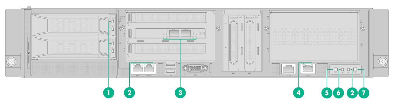
Figure1-1 Front panel LEDs
|
(1) Drive LEDs (upper: Fault/UID LED, lower: Present/Active LED) |
|
|
(2) 1000BASE-T port LEDs |
(3) SFP+ port LEDS |
|
(4) HDM dedicated network port LED |
(5) UID button/LED |
|
(6) Health LED |
(7) Power on/standby button and system power LED |
Table1-1 Drive LED description
|
Fault/UID LED status |
Present/Active LED status |
Description |
|
Flashing amber |
Steady green/Flashing green |
A drive failure is predicted. Replace the drive immediately. |
|
Steady amber |
Steady green/Flashing green |
The drive is faulty. Replace the drive immediately. |
|
Steady blue |
Steady green/Flashing green |
The drive is operating correctly and is selected by the RAID controller. |
|
Off |
Flashing green |
The drive is performing a RAID migration or rebuilding, or the system is reading or writing data to the drive. |
|
Off |
Steady green |
The drive is present but no data is being read or written to the drive. |
|
Off |
Off |
The drive is not securely installed or a drive failure has occurred. |
Table1-2 SFP+ port LED description
|
SFP+ port LED |
LINK |
ACT |
Description |
|
Steady on |
Flashing |
A link is present on the port, and the port is receiving or sending data. |
|
|
Steady on |
Off |
A link is present on the port, and the port is not receiving or sending data. |
|
|
Off |
Off |
No link is present on the port. |
Table1-3 Description for other LEDs and button
|
Button/LED |
Status |
|
1000Base-T Ethernet port LED |
· Steady green—A link is present on the port. · Flashing green—The port is receiving or sending data. · Off—No link is present on the port. |
|
HMD dedicated network port LED |
· Steady green—A link is present on the port. · Flashing green—The port is receiving or sending data. · Off—No link is present on the port. |
|
UID button LED |
· Steady blue—UID LED is activated. The UID LED can be activated by using the following methods: ¡ Press the UID button LED. ¡ Enable UID LED from HDM. · Flashing blue: ¡ Slow flashing—The firmware is being upgraded or the system is being managed from HDM. ¡ Fast flashing—HDM is restarting. To restart HDM, press the UID button LED for eight seconds. · Off—UID LED is not activated. |
|
Health LED |
· Steady green—The system is operating correctly, or a minor alarm has occurred. · Flashing green—Initializing HDM. · Slow flashing amber—A pre-alarm has occurred. · Fast flashing amber—A general alarm has occurred. · Flashing red—A severe alarm has occurred. |
|
Power on/standby button and system power LED |
· Steady green—The system has started. · Flashing green—The system is starting. · Steady amber—The system is in standby state. · Off—No power is present. The reasons might be the following: ¡ No power source is connected. ¡ No power supply is present. ¡ The installed power supplies are faulty. ¡ The system power LED is not connected correctly. |
Rear panel LEDs
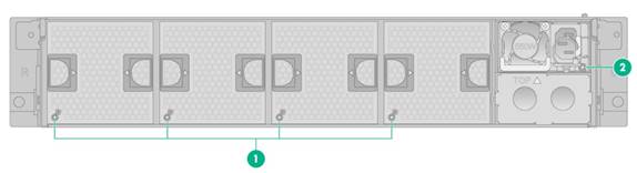
Figure1-2 Rear panel LEDs
|
(1) Fan module status LEDs |
(2) Power supply status LED |
Table1-4 LEDs and buttons on the rear panel
|
LED |
Status |
|
Fan module status LED |
· Steady green—The fan module is operating correctly. · Steady red—The fan module is faulty. · Off—The fan module is not installed securely, or no power is present on the fan module. |
|
Power supply status LED |
· Steady green—The power supply is operating correctly. · Fast flashing green—Power is being input correctly but the system is not powered on. · Slow flashing green—The power supply is for backup and provides no power output. · Steady amber—Either of the following conditions exists: ¡ The power supply is faulty. ¡ The power supply does not have power input, but the other power supply has correct power input. · Flashing amber—An alert has occurred. · Off—Both power supplies do not have power input, which can be caused by incorrect power cord connection or power source shutdown. |
