- Table of Contents
-
- H3C WBC580 G2 Multiservice Access Controller Installation Guide-5W105
- 00-Preface
- 01-Preparing for installation
- 02-Installing and removing the device
- 03-Powering on, powering off, and rebooting the device
- 04-Logging in to the device
- 05-Maintenance
- 06-Appendix A Chassis views and technical specifications
- 07-Appendix B LEDs
- 08-Appendix C Optional transceiver modules
- Related Documents
-
| Title | Size | Download |
|---|---|---|
| 02-Installing and removing the device | 1.58 MB |
Contents
Installing and removing the device
Installation and removal flowchart
About the SL-2U-FR-S short rail kit
Attaching inner rails to the device
Attaching outer rails to the rack
Installing the device in the rack
Connecting a mouse, keyboard, and monitor
Removing the device from a rack
Installing and removing the device
Prerequisites
· You have read "Preparing for installation" carefully.
· All requirements in "Preparing for installation" are met.
Installation and removal flowchart
Figure1-1 Installation flowchart
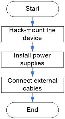
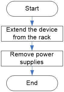
Figure1-2 Removal flowchart
Installing the device
|
|
CAUTION: Keep the tamper-proof seal on a mounting screw on the chassis cover intact, and if you want to open the chassis, contact H3C for permission. Otherwise, H3C shall not be liable for any consequence. |
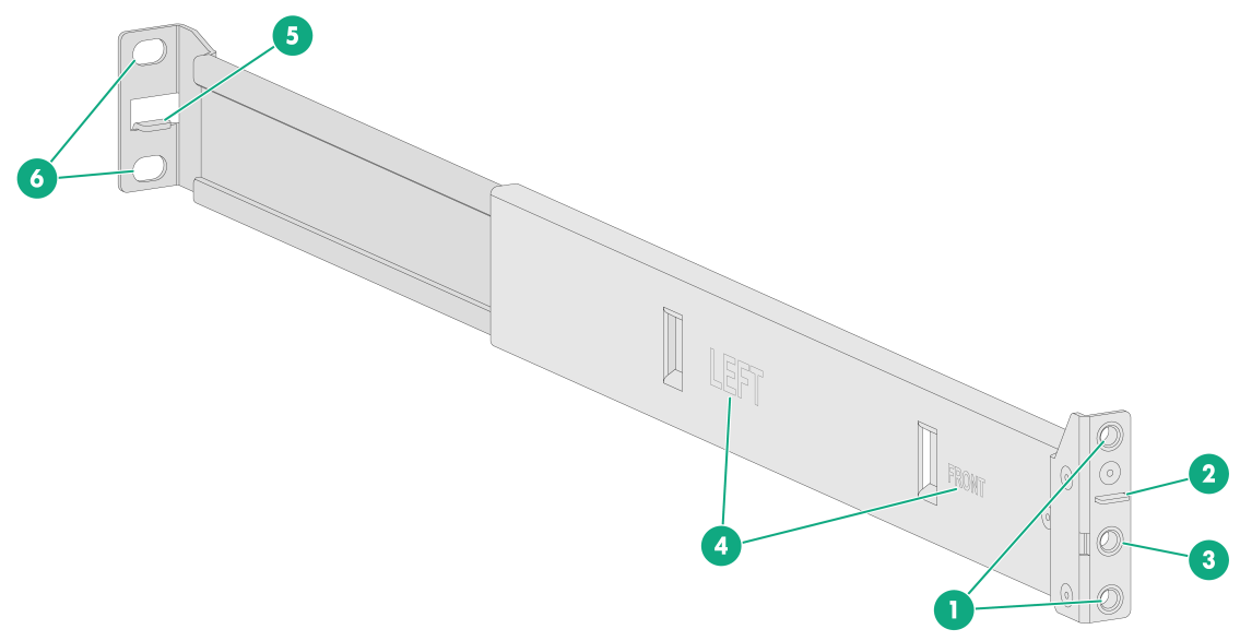
About the SL-2U-FR-S short rail kit
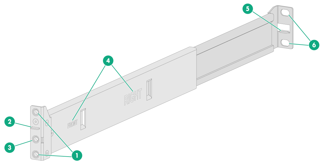
The SL-2U-FR-S short rail kit shipped with the device includes left and right slide rails. Each slide rail has an outer rail and an inner rail. The outer rail is installed on the rack, and the inner rail is installed on the device.
Figure1-3 Left outer rail
|
(1) Front mounting screw holes |
(2) Front mounting clip |
|
(3) Mounting bracket installation hole |
(4) Identification marks |
|
(5) Rear mounting clip |
(6) Rear mounting screw holes |
Figure1-4 Right outer rail
|
(1) Front mounting screw holes |
(2) Front mounting clip |
|
(3) Mounting bracket installation hole |
(4) Identification marks |
|
(5) Rear mounting clip |
(6) Rear mounting screw holes |
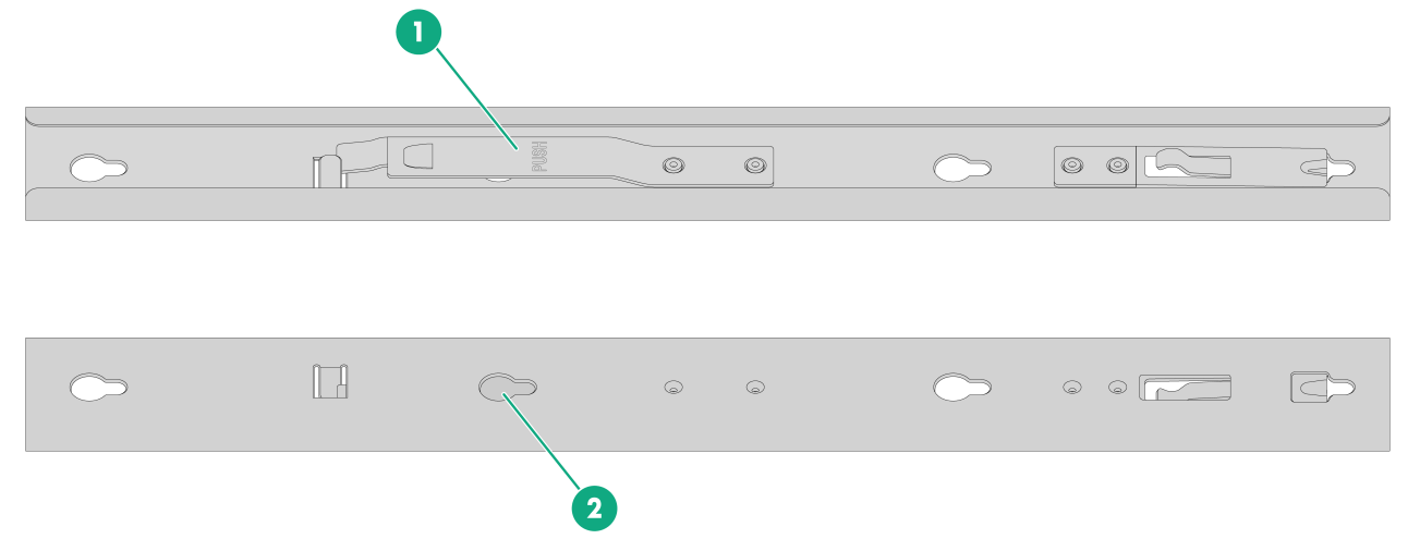
Figure1-5 Inner rail
|
(1) Release tab |
(2) Keyhole slot |
Attaching inner rails to the device
1. Unpack the inner rails.
2. Pressing the release tab on the inner rail, extend each rail to its maximum length.
3. Attach an inner rail to the device.
|
|
IMPORTANT: For some devices, you must first remove the transport security screw before attaching inner rails to them. View the labels on the device carefully to identify the location of transport security screws. |
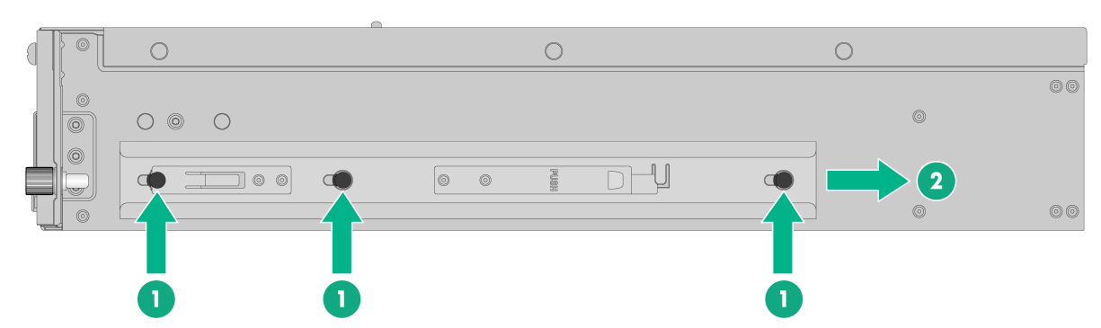
a. As shown by callout 1 in Figure1-6, align the four keyhole slots in the inner rail with the pegs on the chassis side panel and place the inner rail against the side panel.
b. As shown by callout 2 in Figure1-6, slide the rail toward the chassis rear to lock the rail in place on the pegs.
4. Repeat the same procedure to attach the other inner rail to the other side panel of the device.
Figure1-6 Attaching an inner rail to the device
|
|
NOTE: You must set the keyhole slots in the rails over all the four pegs on each side panel of the device. In Figure1-6, a peg is blocked by the release tab and only three pegs are displayed. |
Attaching outer rails to the rack
1. Identify the left and right outer rails.
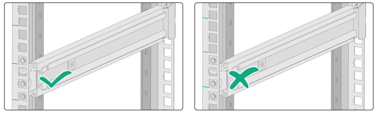
2. Determine and mark the outer rail installation position on the rack posts. Make sure the rails take a 1U of rack space at the same height of the rack posts.
Figure1-7 Correct and wrong installation positions
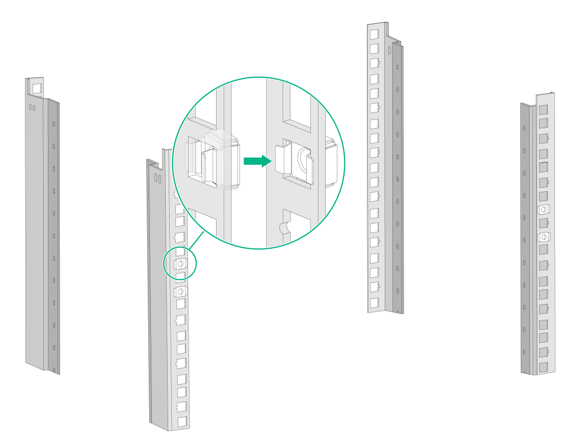
3. As shown in Figure1-8, install two M6 cage nuts at the marked positions on each rear rack post.
The front ends of the outer rails provide threaded screw holes. You are not required to install M6 cage nuts in these screw holes.
Figure1-8 Installing cage nuts
4. Attach an outer rail to the rack.
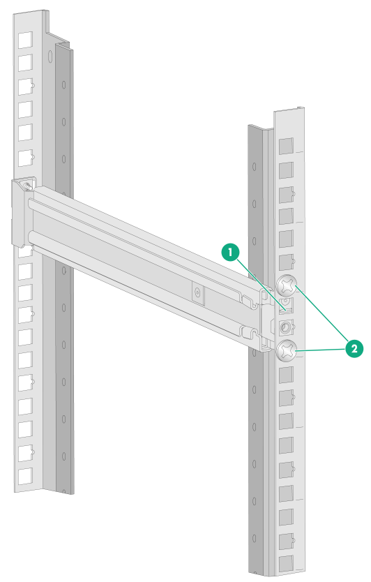
a. Attach the front end of the outer rail to the front rack post.
Align the screw holes in the front end of the outer rail with the marked square holes in the front rack post and insert the mounting clip into the square hole in the rack post, as shown by callout 1 in Figure1-9. Then use two M6 countersunk head screws to secure the front end of the rail to the rack post.
As a best practice, use a torque of 30 kgf·cm (2.94 Nm) to fasten the M6 countersunk head screws.
Figure1-9 Securing the front end of an outer rail to the rack
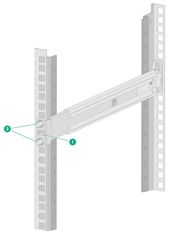
c. Adjust the length of the rail and attach the rear end of the outer rail to the rear rack post.
As shown by callout 1 in Figure1-10, align the screw holes in the rear end of the outer rail with the cage nuts in the rear rack post and insert the mounting clip into the square hole in the rack post. Then use two M6 pan-head screws to secure the rear end of the rail to the rear rack post.
As a best practice, use a torque of 30 kgf·cm (2.94 Nm) to fasten the M6 pan-head screws.
Figure1-10 Securing the rear end of an outer rail to the rack
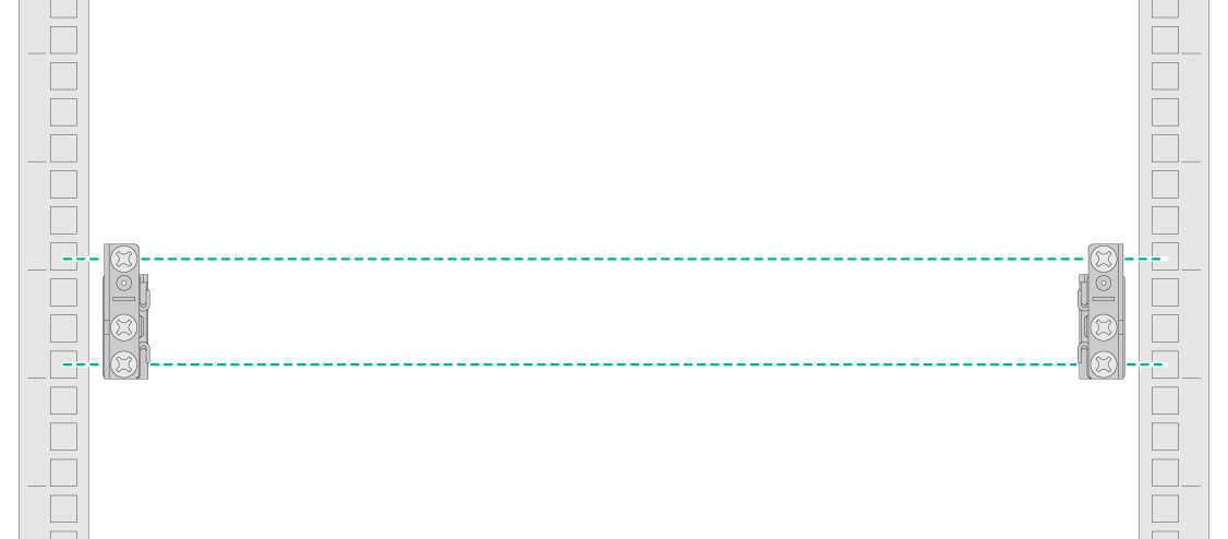
5. Repeat the same procedure to attach the other outer rail to the rack.
Make sure the left and right outer rails are installed at the same height so that the device can be installed safe and level on the rack.
Figure1-11 Left and right outer rails installed
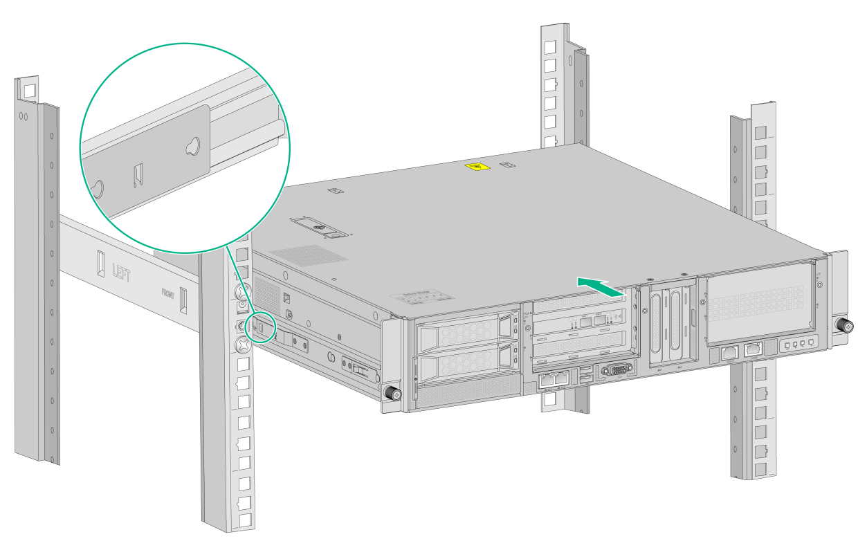
Installing the device in the rack
1. Slide the inner rails on the chassis into the outer rails on the rack posts and push the device into the rack.
|
|
WARNING! Be careful when you slide the device into the rack. Do not let the rails squeeze your fingers. |
Figure1-12 Mounting the device in the rack
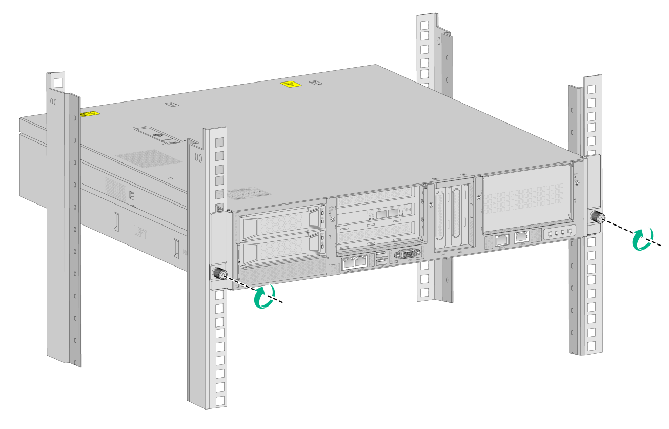
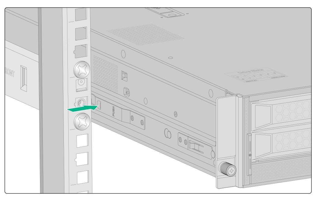
2. Place the mounting brackets of the device flush against the front rack posts. Then use captive screws to secure the mounting brackets to the front rack posts. As a best practice, use a torque of 30 kgf·cm (2.94 Nm) to fasten the captive screws.
Figure1-13 Securing the device to the rack
Installing a power supply
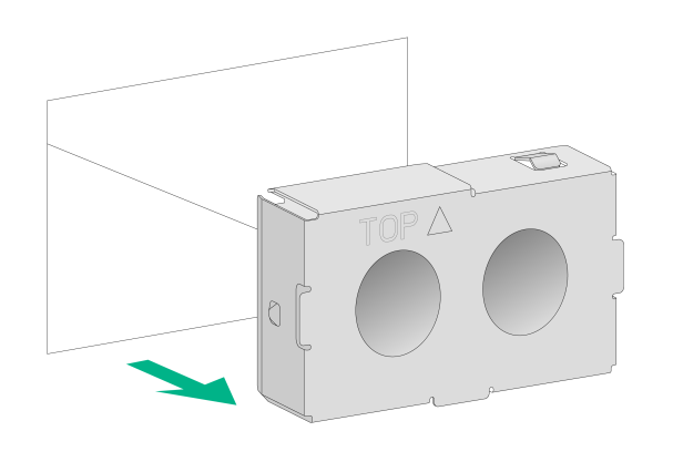
1. Remove the filler panel from the power supply slot.
Figure1-14 Removing the filler panel from the power supply slot
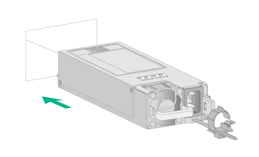
2. Push the power supply into the slot until it snaps into place.
Figure1-15 Installing the power supply
Connecting external cables
Cabling guidelines
|
|
WARNING! To avoid electric shock, fire, or damage to the equipment, do not connect communication equipment to RJ-45 Ethernet ports on the device. |
· For heat dissipation, make sure no cables block the inlet or outlet air vents of the device.
· To easily identify ports and connect/disconnect cables, make sure the cables do not cross.
· Label the cables for easy identification of the cables.
· Wrap unused cables onto an appropriate position on the rack.
Connecting a mouse, keyboard, and monitor
1. Connect one plug of a VGA cable to a VGA connector on the device, and fasten the screws on the plug.
Figure1-16 Connecting a VGA cable
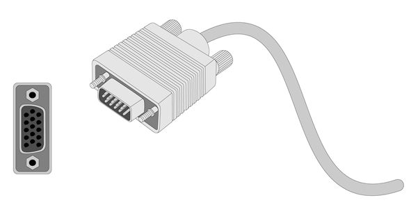
2. Connect the other plug of the VGA cable to the VGA connector on the monitor, and fasten the screws on the plug.
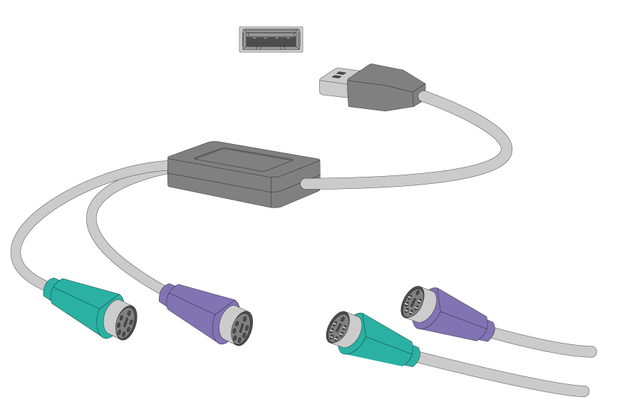
3. Connect the mouse and keyboard.
¡ For a USB mouse and keyboard, directly connect the USB connectors of the mouse and keyboard to the USB connectors on the device.
¡ For a PS2 mouse and keyboard, insert the USB connector of the USB-to-PS2 adapter to a USB connector on the device. Then, insert the PS2 connectors of the mouse and keyboard into the PS2 receptacles of the adapter.
Figure1-17 Connecting a PS2 mouse and keyboard by using a USB-to-PS2 adapter
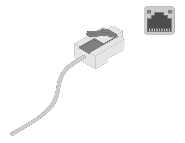
Connecting an Ethernet cable
To connect the device to the network, use one of the two Ethernet ports on the device front panel.
To log in to HDM from the Web interface, use the HDM dedicated network port or HDM shared network port (Ethernet port 1) on the device front panel. For the position of the ports, see "Appendix A Chassis views and technical specifications."
Figure1-18 Connecting an Ethernet cable
Connecting a fiber port
|
|
CAUTION: · To connect a fiber port by using an optical fiber, first install a transceiver module in the port and then connect the optical fiber to the transceiver module. · Insert a dust cap into any open optical fiber connector and a dust plug into any open fiber port or transceiver module port to protect them from contamination and ESD damage. · Never bend an optical fiber excessively. The bend radius of an optical fiber must be not less than 100 mm (3.94 in). · Keep the fiber end clean. · Make sure the Tx and Rx ports on a transceiver module are connected to the Rx and Tx ports on the peer end, respectively. |
No transceiver modules are provided with the device. Purchase transceiver modules yourself as required. For transceiver module specifications, see "Appendix C Optional transceiver modules."
The fiber ports on the device support only LC connectors.
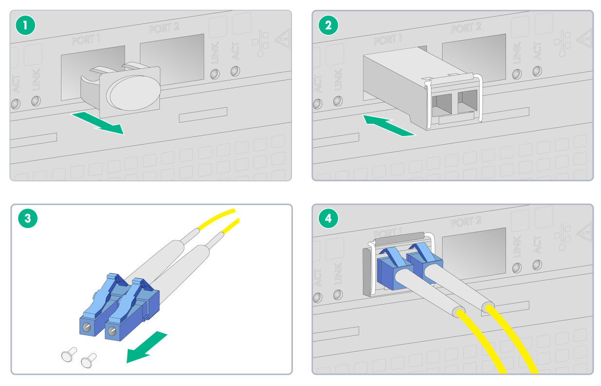
To connect an optical fiber for a fiber port:
1. Remove the dust plug from the fiber port.
2. Remove the dust cap from the transceiver module, and insert the transceiver module slowly into the port.
3. Remove the dust cap from the fiber connectors on the optical fiber.
4. Identify the Rx and Tx ports on the transceiver module. Use the optical fiber to connect the Rx port and Tx port on the transceiver module to the Tx port and Rx port on the peer end, respectively.
Figure1-19 Connecting an optical fiber
5. Examine the fiber port Link LED to verify that the port is operating correctly. For more information about the Link LED, see "Appendix B LEDs."
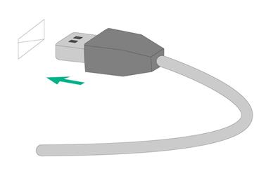
Connecting a USB device
USB devices are hot swappable.
To connect a USB device:
1. Connect the USB device to the USB connector, as shown in Figure1-20.
Figure1-20 Connecting a USB device to a USB connector
2. Verify that the device can identify the USB device.
If the device fails to identify the USB device, download and install the driver of the USB device. If the device still fails to identify the USB device after the driver is installed, replace the USB device.
Connecting the power cord
|
|
WARNING! To avoid damage to the equipment or even bodily injury, use the power cord shipped with the device. |
Before connecting the power cord, make sure the device and components are installed correctly.
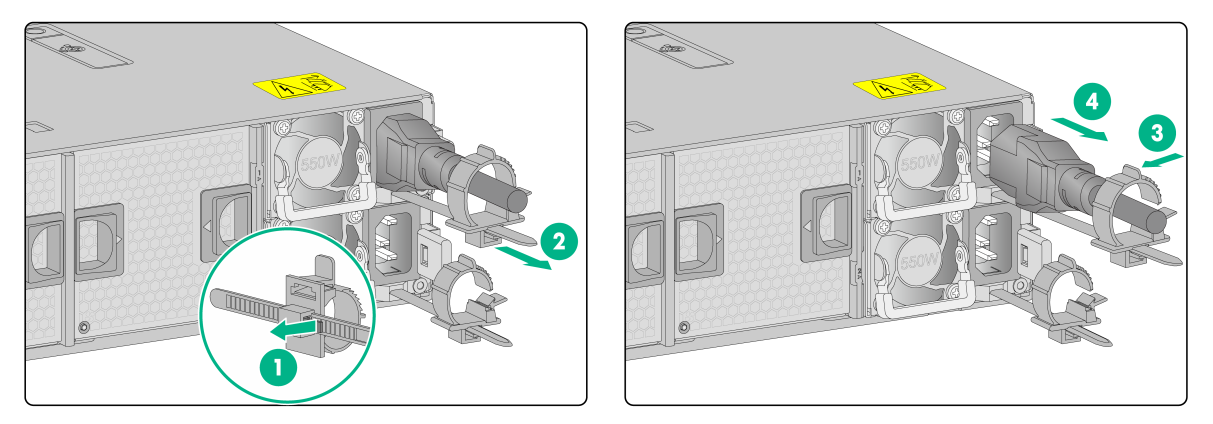
To connect the power cord:
1. Open the latch on the tie mount of the cable clamp and slide the clamp backward.
2. Open the cable clamp, place the power cord through the opening in the cable clamp, and then close the cable clamp.
3. Insert the power cord connector into the receptacle on the power supply.
4. Slide the cable clamp forward until it is flush against the edge of the power cord connector.
5. Connect the other end of the power cord to the power supply system.
Figure1-21 Connecting the power cord
Removing the device from a rack
1. Power down the device. For more information, see "Powering on, powering off, and rebooting the device."
2. Disconnect all cables from the device.
3. Remove the device from the rack.
a. Use a screwdriver to loosen the captive screws on the mounting brackets. Then, slide the device out of the rack until it stops.
b. Supporting the bottom of the device and holding down the release tabs on the inner slides, pull the device all the way out of the rack.
Figure1-22 Pressing the release tab
4. Place the device on a clean, stable antistatic workbench or on the floor.
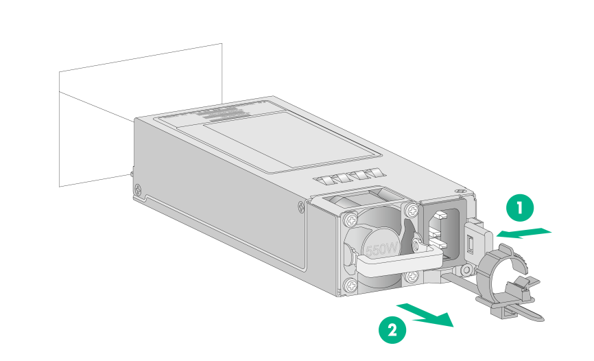
Removing a power supply
The power supplies are hot swappable. If two power supplies are installed and sufficient space is available for replacement, you can replace a power supply without powering off or removing the device from the rack.
To remove a power supply:
1. Power off the device. For more information, see "Powering on, powering off, and rebooting the device."
2. Remove the device from the rack. For more information, see "Removing the device from a rack."
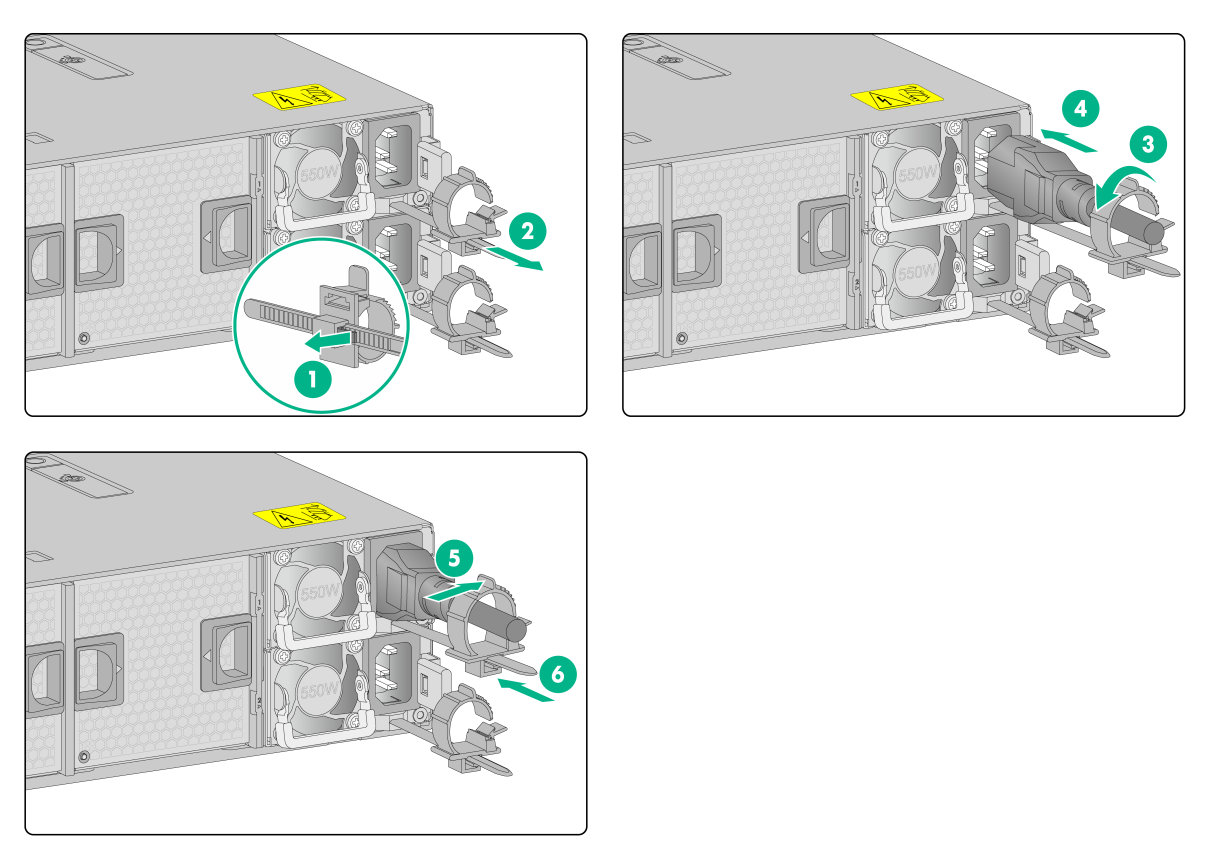
3. Remove the power cord from the power supply:
a. Open the latch on the tie mount of the cable clamp and slide the cable clamp outward.
b. Open the cable clamp and remove the power cord out of the clamp.
c. Disconnect the power cord.
Figure1-23 Removing the power cord
4. Press the retaining latch with your thumb and hold the power supply by its handle to release the power supply. Then pull the power supply slowly out of the slot, as shown in Figure1-24.
Figure1-24 Removing the power supply