- Table of Contents
-
- H3C WBC580 G2 Multiservice Access Controller Installation Guide-5W105
- 00-Preface
- 01-Preparing for installation
- 02-Installing and removing the device
- 03-Powering on, powering off, and rebooting the device
- 04-Logging in to the device
- 05-Maintenance
- 06-Appendix A Chassis views and technical specifications
- 07-Appendix B LEDs
- 08-Appendix C Optional transceiver modules
- Related Documents
-
| Title | Size | Download |
|---|---|---|
| 01-Preparing for installation | 373.46 KB |
Preparing for installation
Safety sign conventions
To avoid bodily injury or damage to the device or its components, make sure you are familiar with the safety signs on the device chassis or its components.
|
Sign |
Description |
|
Circuit or electricity hazards are present. Only H3C authorized or professional device engineers are allowed to service, repair, or upgrade the device.
To avoid bodily injury or damage to circuits, do not open any components marked with the electrical hazard sign unless you have authorization to do so. |
|
|
Electrical hazards are present. Field servicing or repair is not allowed.
To avoid bodily injury, do not open any components with the field-servicing forbidden sign in any circumstances. |
|
|
The surface or component might be hot and present burn hazards.
To avoid being burnt, allow hot surfaces or components to cool before touching them. |
|
|
The device or component is heavy and requires more than one people to carry or move.
To avoid bodily injury or damage to hardware, do not move a heavy component alone. In addition, observe local occupational health and safety requirements and guidelines for manual material handling. |
|
|
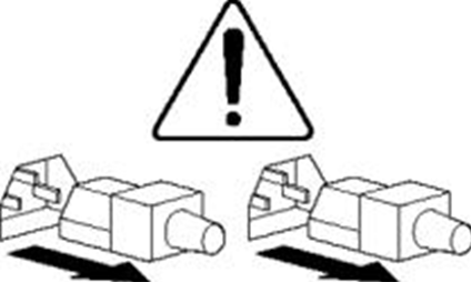
|
The device is powered by multiple power supplies.
To avoid bodily injury from electrical shocks, make sure you disconnect all power supplies if you are performing offline servicing. |
Safety recommendations
To avoid any equipment damage or bodily injury, read the following safety recommendations before installation. Note that the recommendations do not cover every possible hazardous condition.
Safety symbols
When reading this document, note the following symbols:
![]() WARNING means an alert that calls attention to important information that if
not understood or followed can result in personal injury.
WARNING means an alert that calls attention to important information that if
not understood or followed can result in personal injury.
![]() CAUTION means an alert that calls attention to important information that if
not understood or followed can result in data loss, data corruption, or damage
to hardware or software.
CAUTION means an alert that calls attention to important information that if
not understood or followed can result in data loss, data corruption, or damage
to hardware or software.
General safety recommendations
· Make sure the installation site is flat, vibration-free, and away from electromagnetic interferences. Make sure ESD and anti-slip measures are in place.
· Keep the chassis and installation tools away from walk areas.
· Do not place the device on an unstable case or desk. The device might be severely damaged in case of a fall.
· Keep the chassis clean and dust-free.
· Do not place the device near water or in a damp environment. Prevent water or moisture from entering the device chassis.
· Install the device in a standard 19-inch rack.
· If multiple racks exist in an equipment room, connect these racks for stability purposes and ease of installation.
· Make sure the rack is securely seated with the supporting legs closely contacting the floor. All the weight must be supported by the supporting legs.
· Remove a maximum of one device from a rack at one time.
· Use two people to install the device to or pull the device out of a rack to ensure stability. If the installation position is above the chest, use one more people to help adjust the device orientation.
· Make sure the rack is securely seated on the floor before installing or removing the device.
· To ensure good ventilation, install blanks over unused rack space and the empty power supply slot.
· To ensure good ventilation, make sure the air inlet and outlet vents of the device are not blocked. If you are to install multiple devices in a rack, make sure there is a minimum of 2 mm (0.08 in) clearance between every two devices.
· Remove all cables from the device before moving it.
· Make sure the output voltage of the power supplies is as required.
· Use a screwdriver to fasten screws.
· After you move the device from a location below 0°C (32°F) to the equipment room, follow these guidelines to prevent condensation:
¡ Wait a minimum of 30 minutes before unpacking the device.
¡ Wait a minimum of 2 hours before powering on the device.
Electricity safety
|
|
WARNING! If you put the device in standby mode
(system LED in amber) with the |
|
|
CAUTION: As a best practice to avoid device impairment caused by voltage fluctuation and power failure, use a UPS as the external power source. |
· Carefully examine your work area for possible hazards, such as moist floors.
· Locate the emergency power-off switch in the room before installation. Shut off the power immediately if an accident occurs. Remove the power cord if necessary.
· Do not work alone when you operate the device with power on.
· Always verify that the power has been disconnected when you perform operations that require the device to be powered off.
· To avoid device damage or bodily injury, use the power cord supplied with the device.
· Do not use the supplied power cord on any other devices.
· Power off the device before installing or removing any non-hot-swappable hardware options.
Laser safety
|
|
WARNING! · Disconnected optical fibers or transceiver modules might emit invisible laser light. Do not stare into beams or view directly with optical instruments when the router is operating. · Before you remove the optical fiber connector from a fiber port, execute the shutdown command in interface view to shut down the port. |
|
|
CAUTION: · Install dust caps for open optical fiber connectors to protect them from contamination and ESD damage. · Insert dust plugs into open fiber ports and transceiver module ports to protect them from contamination and ESD damage. |
Examining the installation site
The device can only be used indoors. For the device to operate correctly and have a prolonged service time, the installation site must meet the following requirements.
Temperature and humidity
Make sure the temperature and humidity in the equipment room meet the requirements described in Table1-2.
· Lasting high relative humidity can cause poor insulation, electricity leakage, mechanical property change of materials, and metal corrosion.
· Lasting low relative humidity can cause washer contraction and ESD and cause problems including loose mounting screws and circuit failure.
· High temperature can accelerate the aging of insulation materials and significantly lower the reliability and lifespan of the device.
Table1-2 Temperature and humidity requirements for the equipment room
|
Temperature |
Humidity |
|
· Operating temperature: 5°C to 45°C (32°F to 113°F) · Storage temperature: –40°C to +70°C (–40°F to +158°F) |
· Operating humidity: 8% RH to 90% RH, noncondensing · Storage humidity: 5% RH to 95% RH, noncondensing |
|
|
NOTE: The ventilation performance of the device depends on the installation density and ventilation in the rack. In a high-density environment, the available operating temperature might decrease. |
Cleanliness
Dust buildup on the chassis might result in electrostatic adsorption, which causes poor contact of metal components and contact points, especially when indoor relative humidity is low. In the worst case, electrostatic adsorption can cause communication failure.
Table1-3 Dust concentration limit in the equipment room
|
Substance |
Particle diameter |
Concentration limit |
|
Dust particles |
≥ 5 µm |
≤ 3 x 10⁴ particles/m3 (No visible dust on desk in three days) |
|
Dust (suspension) |
≤ 75 µm |
≤ 0.2 mg/m3 |
|
Dust (sedimentation) |
75 µm to 150 µm |
≤ 1.5 mg/(m2h) |
|
Sand |
≥ 150 µm |
≤ 30 mg/m3 |
The equipment room must also meet limits on salts, acids, and sulfides to eliminate corrosion and premature aging of components, as shown in Table1-4.
Table1-4 Harmful gas limits in the equipment room
|
Gas |
Max. (mg/m3) |
|
SO2 |
0.2 |
|
H2S |
0.006 |
|
NH3 |
0.05 |
|
Cl2 |
0.01 |
|
NO2 |
0.04 |
Cooling
To provide adequate cooling for the device, follow these guidelines:
· Reserve a minimum clearance of 10 cm (3.94 in) around the device.
· Make sure the installation site has a good cooling system.
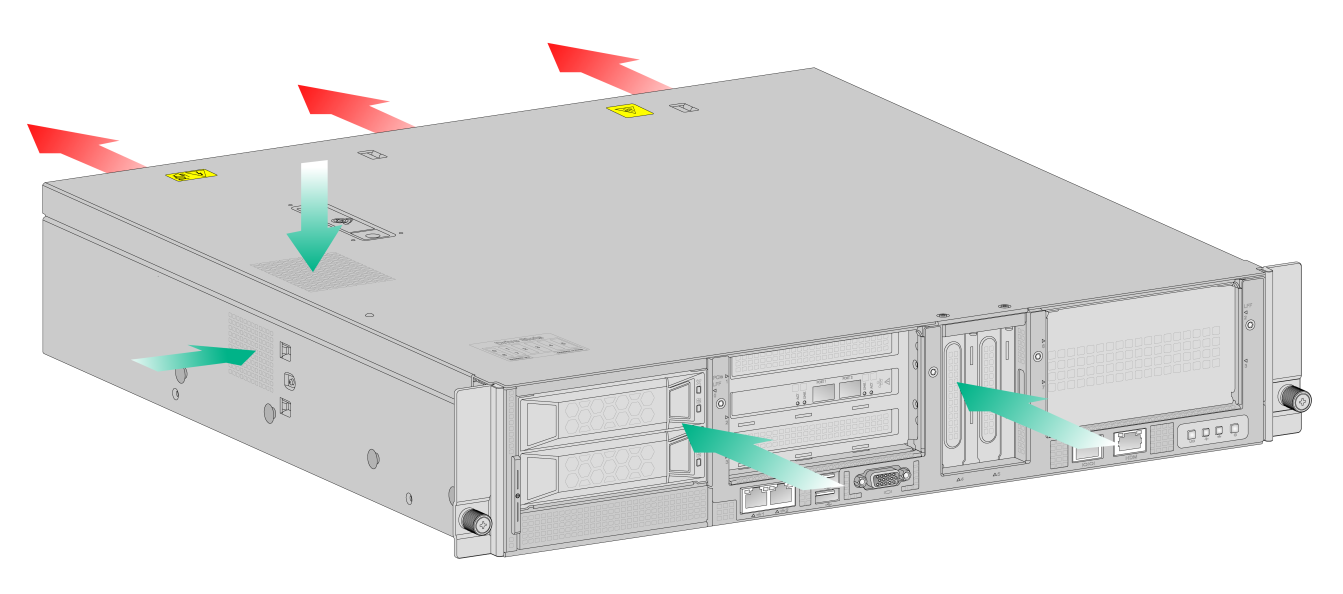
· Identify the cold and hot aisle arrangement at the installation site, and make sure the device draws in air from the cold aisle and exhausts air to the hot aisle.
· Identify the airflow directions of the upper and lower devices, and make sure hot air exhausted from the lower devices does not circulate into the upper devices.
Figure1-1 Airflow through the device
Rack
To rack-mount the device, make sure the rack meets the following requirements:
· The rack is sturdy enough to support the weights of the device and its accessories.
· The rack is grounded reliably.
· The rack can accommodate the device. See Table1-5 for the requirements for rack dimensions.
Table1-5 Requirements for rack dimensions
|
Installation method |
Chassis dimensions |
Distance between the front and rear rack posts |
Rack requirements |
|
Using mounting brackets and an SL-2U-FR-S short rail kit |
· Height—87 mm (3.43 in), 2 RU · Width—440 mm (17.32 in) · Total depth—450 mm (17.72 in) |
350 to 450 mm (13.78 to 17.72 in) |
· Depth (recommended)—A minimum of 800 mm (31.50 in). · Distance between the front rack posts and front door—A minimum of 100 mm (3.94 in). · Distance between the front rack posts and rear door—A minimum of 550 mm (21.65 in). |
|
|
IMPORTANT: For the rack door to close easily, make sure the rack meets the depth requirements described in Table1-5. |
|
|
NOTE: The total depth is the depth of the chassis when it is fully configured with components and cables. |
Altitude
To ensure correct operation of the device, make sure the room altitude meets the requirements as described in Table1-6.
Table1-6 Altitude requirements
|
Item |
Description |
|
Operating altitude |
–60 m to +3000 m (–196.85 ft to +9842.52 ft) The allowed maximum temperature decreases by 0.33°C (32.59°F) as the altitude increases by 100 m (328.08 ft) from 900 m (2952.76 ft) |
|
Storage altitude |
–60 m to +5000 m (–196.85 ft to +16404.20 ft) |
ESD prevention
To prevent electrostatic discharge (ESD), follow these guidelines:
· Make sure the rack is reliably grounded.
· Take dust-proof measures for the equipment room.
· Maintain the humidity and temperature in the equipment room at acceptable levels.
· When working with the device, always wear an ESD wrist strap and ESD garment. Make sure the wrist strap makes good skin contact and is reliably grounded.
· Use foldable antistatic mat and portable repair kit.
EMI
All electromagnetic interference (EMI) sources, from outside or inside of the device and application system, adversely affect the device in the following ways:
· A conduction pattern of capacitance coupling.
· Inductance coupling.
· Electromagnetic wave radiation.
· Common impedance (including the grounding system) coupling.
To prevent EMI, use the following guidelines:
· Take effective measures to filter interference from the power grid.
· Keep the device far away from radio transmitting stations, radar stations, and high-frequency devices.
· Use electromagnetic shielding, for example, shielded interface cables, when necessary.
· To prevent signal ports from getting damaged by overvoltage or overcurrent caused by lightning strikes, route interface cables only indoors.
Lightning protection
To enhance lightning protection for the device, follow these guidelines:
· Make sure the AC power outlet is reliably grounded.
· Install a surge protected power strip at the power input end.
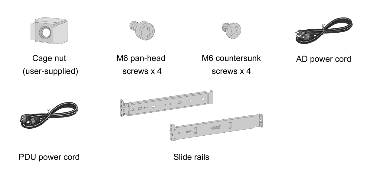
Installation accessories
Figure1-2 Installation accessories
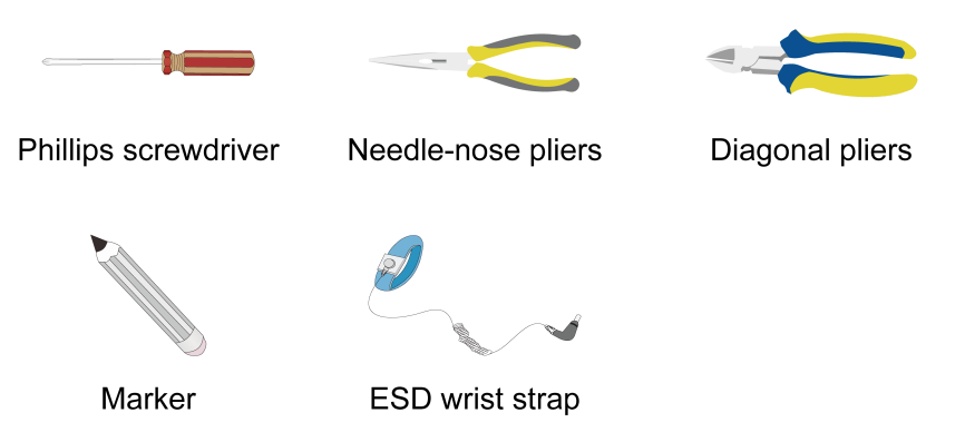
Installation tools
No installation tools are provided with the device. Prepare them yourself as required.
Figure1-3 Installation tools
Pre-installation checklist
Table1-7 Pre-installation checklist
|
Item |
Requirements |
Result |
|
|
Installation site |
Ventilation |
· A minimum clearance of 10 cm (3.9 in) is reserved around the chassis. · The installation site has a good ventilation system. |
|
|
Operating temperature |
5°C to 45°C (32°F to 113°F). |
|
|
|
Operating humidity |
8% RH to 90% RH, noncondensing |
|
|
|
Cleanliness |
· Dust concentration ≤ 3 x 10⁴ particles/m3. · No visible dust on desk within three days. |
|
|
|
ESD prevention |
· The device is reliably grounded. · Dust-proof measures are taken in the equipment room. · Humidity and temperature are maintained in the acceptable range. |
|
|
|
EMI prevention |
· Effective measures are taken for filtering interference from the power grid. · The protection ground of the device is away from the grounding facility of power equipment or lightning protection grounding facility. · The device is far away from radio transmitting stations, radar stations, and high-frequency devices. · Electromagnetic shielding, for example, shielded interface cables, is used as required. |
|
|
|
Lightning protection |
· The AC power source is reliably grounded. · (Optional.) Network port lightning protectors are available. |
|
|
|
Electricity safety |
· A UPS is available. · The power-off switch in the equipment room is identified and accessible so that the power can be immediately shut off when an accident occurs. |
|
|
|
Rack installation |
· The rack has good ventilation performance. · The rack is stable and strong enough to support the device and the accessories attached to the device. · The rack size is suitable for the device installation. · The clearance around the rack meets the ventilation requirements. |
|
|
|
Safety precautions |
The device is far away from any sources of heat or moisture. |
|
|
|
Accessories |
Installation accessories supplied with the device are available. |
|
|
|
Reference |
· Documents shipped with the device are available. · Online documents are available. |
|
|
