- Table of Contents
-
- H3C G3G5 Servers Storage Controller User Guide-6W108
- 00-Preface
- 01-Storage controller overview
- 02-Storage controller features
- 03-Configuring an embedded RSTe RAID controller
- 04-Configuring an NVMe VROC module
- 05-Configuring a P430 storage controller
- 06-Configuring a 1000 storage controller
- 07-Configuring a 9361 94xx L460 P5408 H5408 storage controller
- 08-Configuring an H460, P460, P240 or P4408 storage controller
- 09-Configuring a 9300 storage controller
- 10-Configuring a 9311 storage controller
- 11-Configuring an LSI 9400 or 9500 series storage controller
- 12-Configuring a RAID-MARVELL-SANTACRUZ-LP-2i storage controller
- 13-Appendix A Troubleshooting storage controllers
- 14-Appendix B RAID arrays and fault tolerance
- Related Documents
-
| Title | Size | Download |
|---|---|---|
| 10-Configuring a 9311 storage controller | 5.81 MB |
Configuring an HBA-LSI-9311-8i storage controller
|
|
NOTE: The BIOS screens might vary by the BIOS version. The screenshots in this chapter are for illustration only. |
About the HBA-LSI-9311-8i storage controller
The HBA-LSI-9311-8i storage controller supports 12-Gbps data channels. For storage controller details, access http://www.h3c.com/en/home/qr/default.htm?id=66.
Features
RAID levels
Table 1 shows the minimum number of drives required by each RAID level and the maximum number of failed drives supported by each RAID level. For more information about RAID levels, see "Appendix B RAID arrays and fault tolerance."
Table 1 RAID levels and the numbers of drives for each RAID level
|
RAID level |
Min. drives required |
Max. failed drives |
|
RAID 0 |
2 |
0 |
|
RAID 1 |
2 |
1 |
|
RAID 1E |
3 |
(n-1)/2, where n is the number of drives in the RAID 1E array. |
|
RAID 10 |
4 |
n, where n is the number of RAID 1 arrays in the RAID 10 array. |
|
|
NOTE: Take an HBA-LSI-9311-8i storage controller as an example. The valid range for the number of member drives in RAID 1E array for this storage controller are odd numbers between 3 and 9, that is, 3, 5, 7, and 9. |
Hot spare drives
You can configure hot spare drives to improve data security. A hot spare drive is a standby drive that does not store any data. When a drive in a redundant RAID fails, a spare drive automatically replaces the failed drive and rebuilds the data of the failed drive.
For information about types of hot spare drives, see hot spare drives in "Storage controller features."
Restrictions and guidelines for RAID configuration
As a best practice, install drives that do not contain RAID information.
To avoid degraded RAID performance or RAID creation failures, make sure all drives in the RAID are the same type (HDDs or SSDs) and have the same connector type (SAS or SATA).
For efficient use of storage, use drives that have the same capacity to build a RAID. If the drives have different capacities, the lowest capacity is used across all drives in the RAID.
Configuring RAID arrays in UEFI mode
This section describes how to configure RAID arrays through a storage controller in UEFI mode. For more information about how to enter the BIOS and set the boot mode to UEFI, see the BIOS user guide for the server.
RAID arrays configuration tasks at a glance
To configure RAID arrays in UEFI mode, perform the following tasks:
· Accessing the controller configuration screen
· (Optional.) Configuring hot spare drives
· (Optional.) Deleting a RAID array
· (Optional.) Clearing RAID array information on the drive
· (Optional.) View basic controller properties
· (Optional.) Changing controller properties
· (Optional.) Viewing drive properties
· (Optional.) Locating drives
Accessing the controller configuration screen
1. Access the BIOS. Press Delete, Esc, or F2 as prompted during server POST to open the BIOS setup screen as shown in Figure 1. For some servers, the Front Page screen opens, and you must select Device Management before proceeding to the next step.
For how to navigate screens and modify settings, see the operation instructions at the lower right corner.

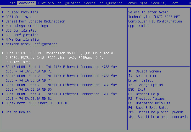
2. Access the LSI SAS3 MPT Controller SAS3008 submenu. Select Advanced > LSI SAS3 MPT Controller SAS3008, and press Enter.
Figure 2 Advanced screen
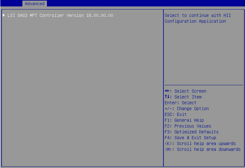
3. On the screen as shown in Figure 3, select LSI SAS3 MPT Controller Version 18.00.00.00, and press Enter.
Figure 3 Selecting the LSI SAS3 MPT controller
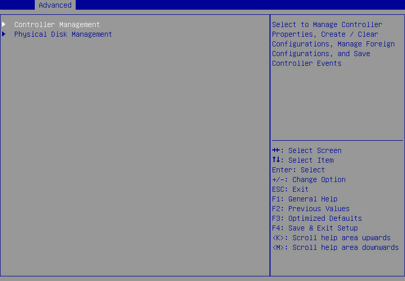
The controller configuration screen as shown in Figure 4 opens.
Figure 4 Controller configuration screen
Creating RAID 0
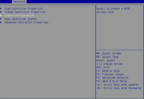
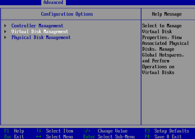
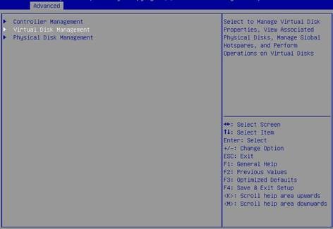
1. On the storage controller configuration screen as shown in Figure 5, select Controller Management and press Enter.
Figure 5 Storage controller configuration screen

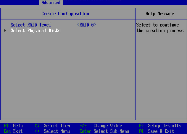
2. On the screen as shown in Figure 6, select Create Configuration and press Enter.
Figure 6 Selecting Create Configuration

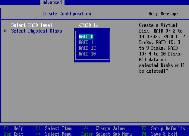
3. On the screen as shown in Figure 7, select Select RAID level and then RAID 0, and then press Enter.
Figure 7 Setting the RAID level
4. On the screen as shown in Figure 8, select Select Physical Disks, and then press Enter.
Figure 8 Selecting Select Physical Disks
5. On the screen as shown in Figure 9, select the target drives. ([Enabled] following a drive means that the drive has been selected.) Then, select Apply Changes and press Enter.
Figure 9 Selecting the target drives

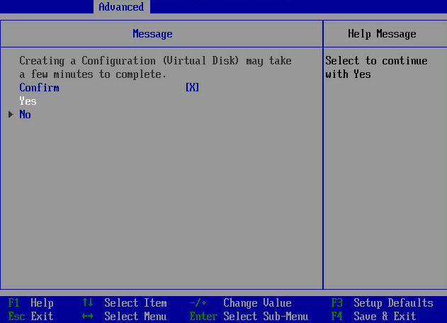
6. On the screen as shown in Figure 10, select Confirm, select Yes, and press Enter.
Figure 10 Confirming the configuration

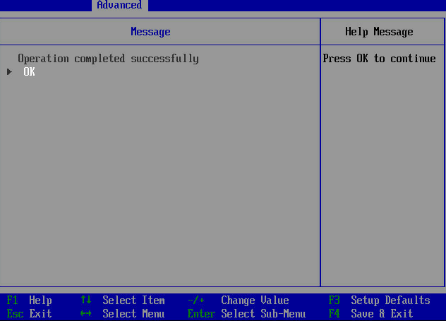
7. On the screen as shown in Figure 11, select OK to return to the storage controller configuration screen.
Figure 11 Completing RAID array configuration

8. Select Virtual Disk Management and press Enter as shown in Figure 12.
Figure 12 Storage controller configuration screen

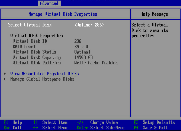
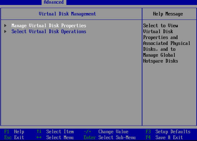
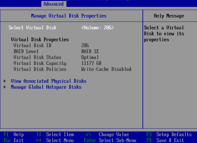
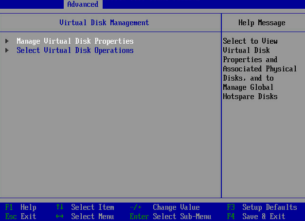
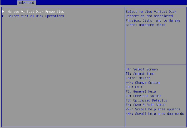
9. On the screen as shown in Figure 13, select Manage Virtual Disk Properties and press Enter.
Figure 13 Virtual Drive Management screen

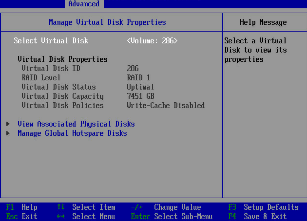
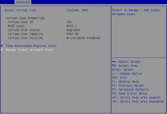
10. On the screen as shown in Figure 14, select View Associated Drives and press Enter. You can view the detailed information about the RAID array, including name, level, and drive information.
Figure 14 Selecting View Associated Drives
Creating RAID 1
1. On the storage controller configuration screen as shown in Figure 15, select Controller Management and press Enter.
Figure 15 Storage controller configuration screen

2. On the screen as shown in Figure 16, select Create Configuration and press Enter.
Figure 16 Selecting Create Configuration
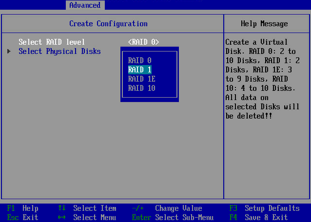
3. On the screen as shown in Figure 17, select Select RAID level and then RAID 1, and then press Enter.
Figure 17 Setting the RAID level
4. On the screen as shown in Figure 18, select Select Physical Disks, and then press Enter.
Figure 18 Selecting Select Physical Disks

5. On the screen as shown in Figure 9, select the target drives. ([Enabled] following a drive means that the drive has been selected.) Then, select Apply Changes and press Enter.
Figure 19 Selecting the target drives

6. On the screen as shown in Figure 20, select Confirm, select Yes, and press Enter.
Figure 20 Confirming the configuration

7. On the screen as shown in Figure 21, select OK to return to the storage controller configuration screen.
Figure 21 Completing RAID array configuration

8. Select Virtual Disk Management and press Enter as shown in Figure 22.
Figure 22 Storage controller configuration screen
9. On the screen as shown in Figure 23, select Manage Virtual Disk Properties and press Enter.
Figure 23 Virtual Drive Management screen
10. On the screen as shown in Figure 24, select View Associated Drives and press Enter. You can view the detailed information about the RAID array, including name, level, and drive information.
Figure 24 Selecting View Associated Drives
Creating RAID 1E
1. On the storage controller configuration screen as shown in Figure 25, select Controller Management, and press Enter.
Figure 25 Storage controller configuration screen

2. On the screen as shown in Figure 26, select Create Configuration and press Enter.
Figure 26 Selecting Create Configuration
3. On the screen as shown in Figure 27, select Select RAID level and then RAID 1E, and then press Enter.
Figure 27 Setting the RAID level

4. On the screen as shown in Figure 28, select Select Physical Disks and press Enter.
Figure 28 Selecting Select Physical Disks

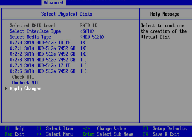
5. On the screen as shown in Figure 29, select the target drives. ([Enabled] following a drive means that the drive has been selected.) Then, select Apply Changes and press Enter.
Figure 29 Selecting the target drives
6. On the screen as shown in Figure 30, select Confirm, select Yes, and press Enter.
Figure 30 Confirming the configuration
7. On the screen as shown in Figure 31, select OK to return to the storage controller configuration screen.
Figure 31 Completing RAID array configuration

8. Select Virtual Disk Management and press Enter as shown in Figure 32.
Figure 32 Storage controller configuration screen

9. On the screen as shown in Figure 33, select Manage Virtual Disk Properties and press Enter.
Figure 33 Virtual Drive Management screen

10. On the screen as shown in Figure 34, select View Associated Drives and press Enter. You can view the detailed information about the RAID array, including name, level, and drive information.
Figure 34 Selecting View Associated Drives
Creating RAID 10
1. On the storage controller configuration screen as shown in Figure 35, select Controller Management and press Enter.
Figure 35 Storage controller configuration screen
2. On the screen as shown in Figure 36, selecting Create Configuration and press Enter.
Figure 36 Selecting Create Configuration
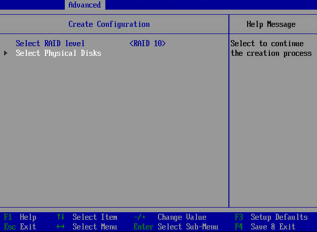
3. On the screen as shown in Figure 37, select Select RAID Level and then RAID 10, and then press Enter.
Figure 37 Setting the RAID level

4. On the screen as shown in Figure 38, select Select Physical Disks and press Enter.
Figure 38 Selecting Select Physical Disks
5. On the screen as shown in Figure 39, select the target drives. ([Enabled] following a drive means that the drive has been selected.) Then, select Apply Changes and press Enter.
Figure 39 Selecting the target drives

6. On the screen as shown in Figure 40, select Confirm, select Yes, and press Enter.
Figure 40 Confirming the configuration

7. On the screen as shown in Figure 41, select OK to return to the storage controller configuration screen.
Figure 41 Completing RAID array configuration
8. Select Virtual Disk Management and press Enter as shown in Figure 42.
Figure 42 Storage controller configuration screen
9. On the screen as shown in Figure 43, select Manage Virtual Disk Properties and press Enter.
Figure 43 Virtual Drive Management screen
10. On the screen as shown in Figure 44, select View Associated Drives and press Enter. You can view the detailed information about the RAID array, including name, level, and drive information.
Figure 44 Selecting View Associated Drives

Configuring hot spare drives
1. On the storage controller configuration screen as shown in Figure 45, select Virtual Disk Management and press Enter.
Figure 45 Storage controller configuration screen

2. Select Manage Virtual Disk Properties and press Enter.
Figure 46 Selecting Manage Virtual Disk Properties
3. On the screen as shown in Figure 47, select Manage Global Hotspare Disks and press Enter.
Figure 47 Selecting Manage Global Hotspare Disks
4. On the screen as shown in Figure 48, select the target drives. ([Enabled] following a drive means that the drive has been selected.) Then, select Assign Global Hotspare Disk and press Enter.
Figure 48 Selecting the target drives

Deleting a RAID array
1. On the storage controller configuration screen as shown in Figure 49, select Virtual Disk Management and press Enter.
Figure 49 Storage controller configuration screen

2. Select Select Virtual Disk Properties and press Enter.
Figure 50 Selecting Select Virtual Disk Properties
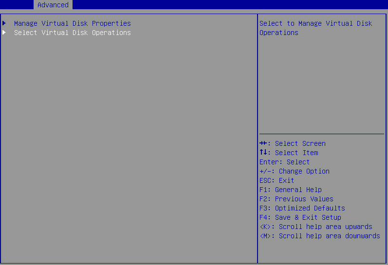
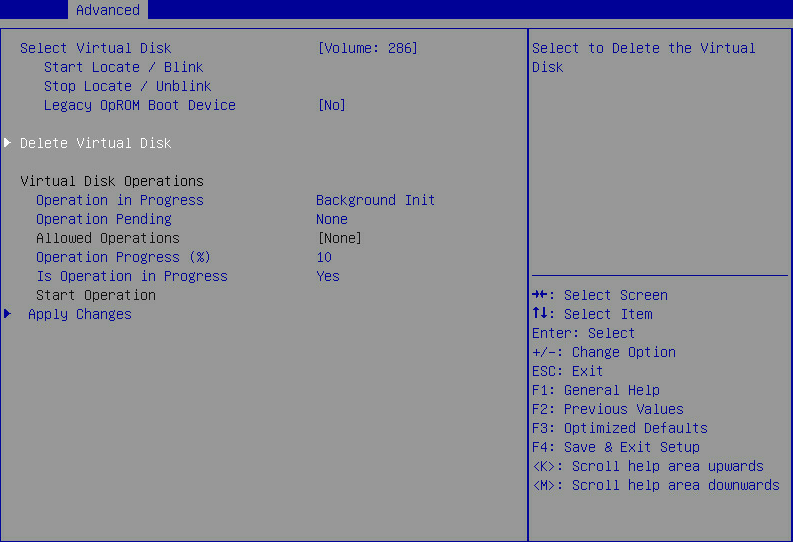
3. On the screen as shown in Figure 51, select Delete Virtual Disk and press Enter.
Figure 51 Selecting Delete Virtual Disk
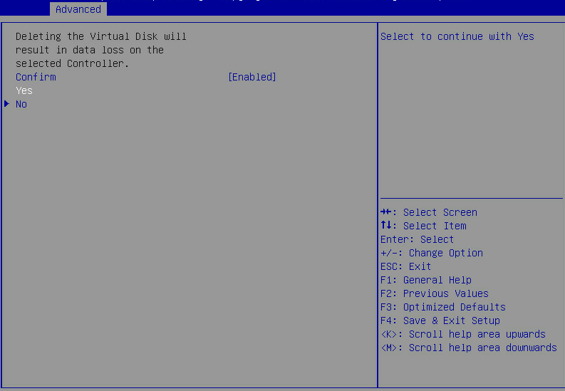
4. On the screen as shown in Figure 52, select Confirm and press Enter. On the dialog box that opens, select Enabled and press Enter. Then, select Yes and press Enter.
Figure 52 Confirming the deletion
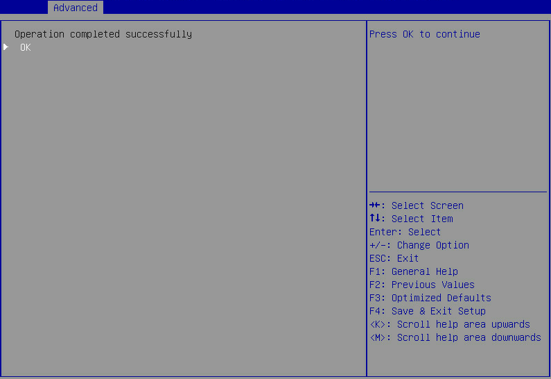
When the operation is complete, the screen as shown in Figure 53 opens.
Figure 53 Completing the operation
Clearing RAID array information on the drive
This task allows you to clear remaining RAID array information on the drive for reconfiguring RAID array on the drive.
To clear RAID array information on the drive:
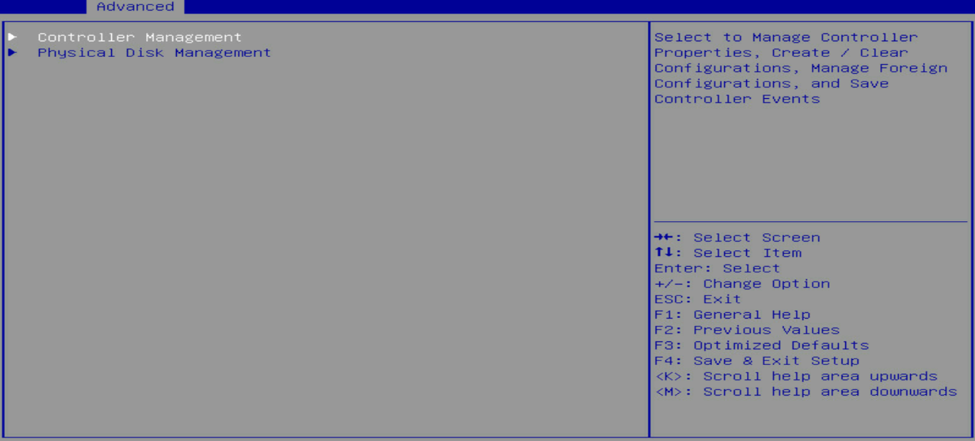
1. On the storage controller configuration screen as shown in Figure 54, select Controller Management and press Enter.
Figure 54 Storage controller configuration screen
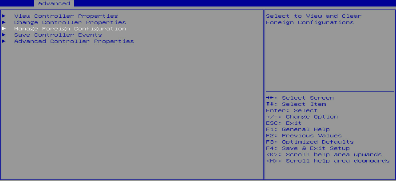
2. On the screen as shown in Figure 55, select Manage Foreign Configuration and press Enter.
Figure 55 Selecting Manage Foreign Configuration
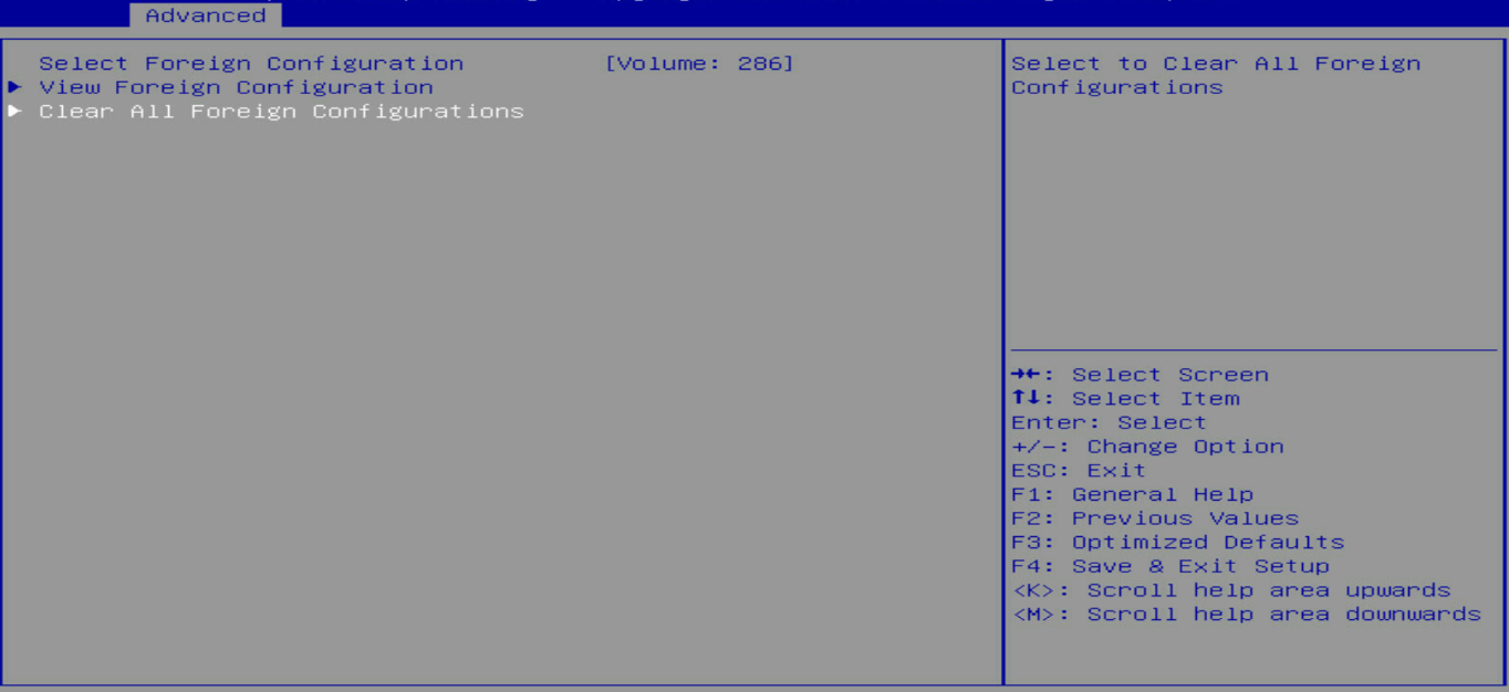
3. On the screen as shown in Figure 56, select Clear All Foreign Configuration and press Enter.
Figure 56 Selecting Clear Foreign Configuration
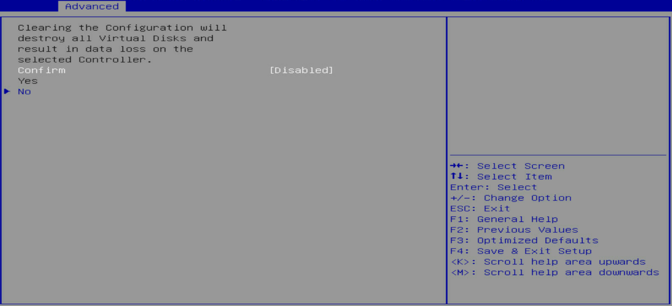
4. On the screen as shown in Figure 57, select Confirm and press Enter. On the dialog box that opens, select Enabled and press Enter. Then, select Yes and press Enter.
Figure 57 Confirming the operation
View basic controller properties
1. On the storage controller configuration screen as shown in Figure 58, select Controller Management and press Enter.
Figure 58 Storage controller configuration screen

2. On the screen as shown in Figure 59, select View Controller Properties and press Enter.
Figure 59 Selecting View Controller Properties

3. View the controller properties on the screen as shown in Figure 60.
Table 2 describes the properties of the controller.
Figure 60 Viewing controller properties
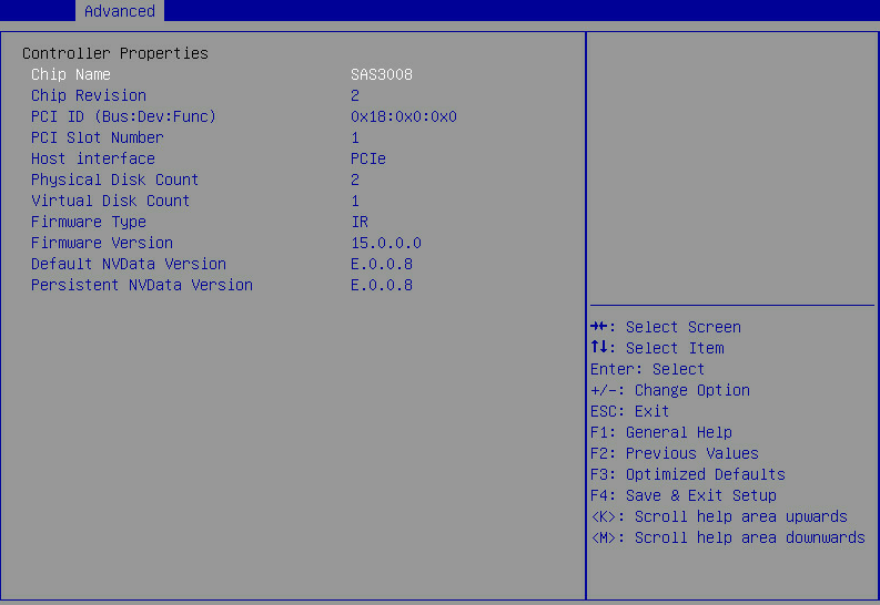
Table 2 Properties of the storage controller
|
Parameter |
Description |
|
Chip Revision |
Version of the chip. |
|
Host interface |
Host interface type. |
|
Persistent NVData Version |
Current NVData version. |
Changing controller properties
1. On the storage controller configuration screen as shown in Figure 61, select Controller Management and press Enter.
Figure 61 Storage controller configuration screen
2. On the screen as shown in Figure 62, select Change Controller Properties and press Enter.
Figure 62 Selecting Change Controller Properties

3. On the screen as shown in Figure 63, change the controller settings as needed, select Apply Changes, and press Enter.
Figure 63 Changing advanced controller settings

Figure 64 Parameter description
|
Parameter |
Description |
|
Rebuild Rate |
Percentage of I/O resources occupied by RAID rebuild when a new hard drive is installed or a failed hard disk is replaced with a hot spare disk. |
Viewing drive properties
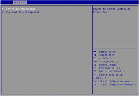
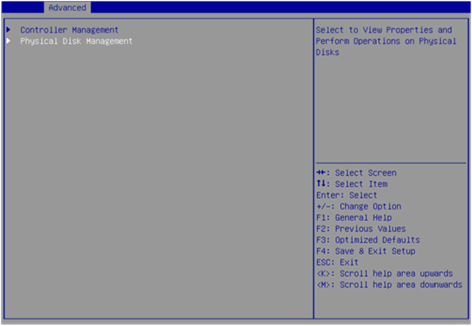
1. On the storage controller configuration screen as shown in Figure 65, select Physical Disk Management and press Enter.
Figure 65 Storage controller configuration screen

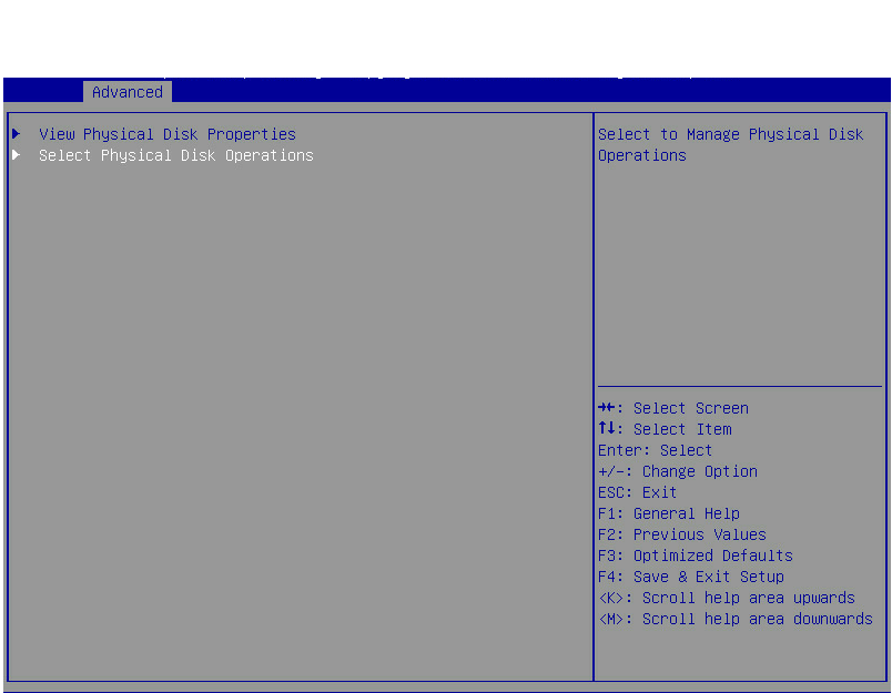
2. On the screen as shown in Figure 66, select View Physical Disk Properties and press Enter.
Figure 66 Selecting View Physical Disk Properties

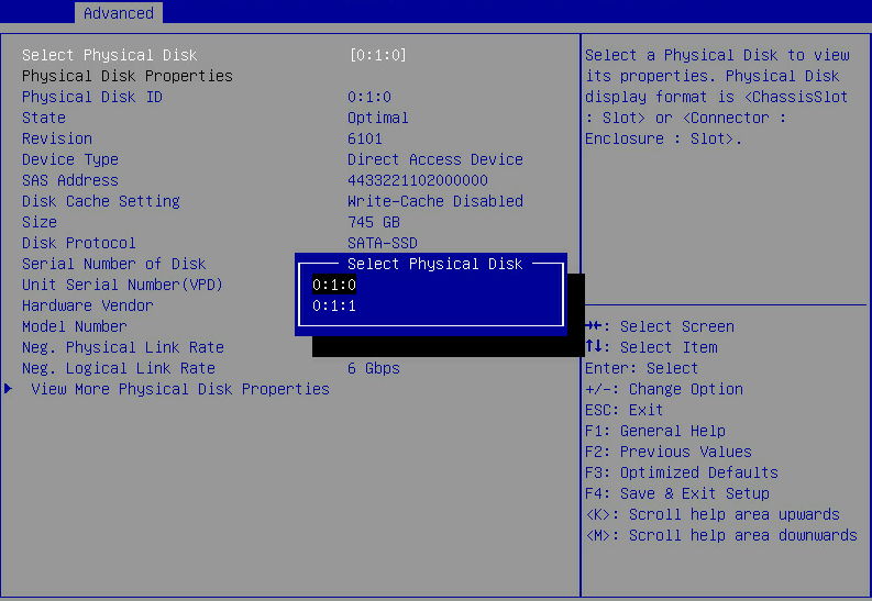
3. On the screen as shown in Figure 67, select Select Physical Disk. On the pop-up window that opens, select the physical drive you want to view and press Enter.
Figure 67 Selecting a physical drive
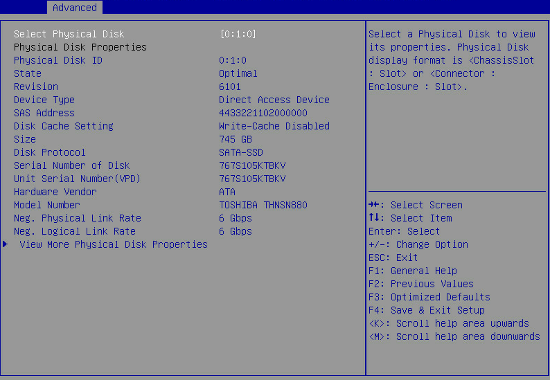
4. View properties of the physical drive on the screen as shown in Figure 68.
You can select View More Physical Disk Properties for more information.
Figure 68 Viewing drive properties
Locating drives
1. On the storage controller configuration screen as shown in Figure 69, select Physical Disk Management and press Enter.
Figure 69 Storage controller configuration screen
2. On the screen as shown in Figure 70, select Select Physical Disk Operations, and press Enter.
Figure 70 Selecting physical disk operations
3. On the screen as shown in Figure 71, select Select Physical Disk. On the pop-up window that opens, select the physical drive you want to locate and press Enter.
Figure 71 Selecting a physical drive
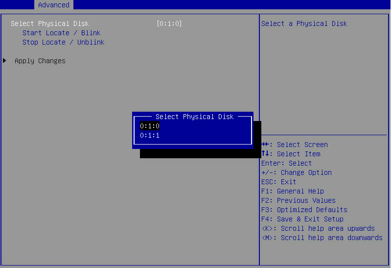
4. Select Start Locate/Blink and press Enter.
5. On the server, identify the physical drive of which the Fault/UID LED is steady blue.
Configuring RAID arrays in legacy mode
This section describes how to configure RAID arrays through a storage controller in legacy mode. For more information about how to enter the BIOS and set the boot mode to legacy, see the BIOS user guide for the server.
RAID array configuration tasks at a glance
To configure RAID arrays in legacy mode, perform the following tasks:
· Accessing the controller configuration screen
· (Optional.) Configuring hot spare drives
· (Optional.) Deleting a RAID array
· (Optional.) Running consistency check
· (Optional.) Viewing drive properties
· (Optional.) Locating drives
· (Optional.) Clearing RAID information or verifying drives
· (Optional.) Setting advanced controller properties
· (Optional.) Configuring boot options
Accessing the controller configuration screen
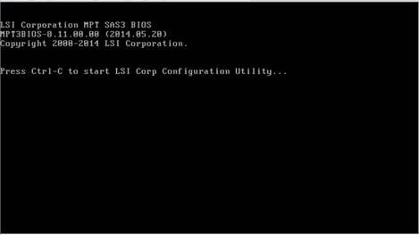
1. During server POST, press Ctrl+C on the screen as shown in Figure 72 to open the controller configuration screen.
Figure 72 Legacy BIOS setup screen
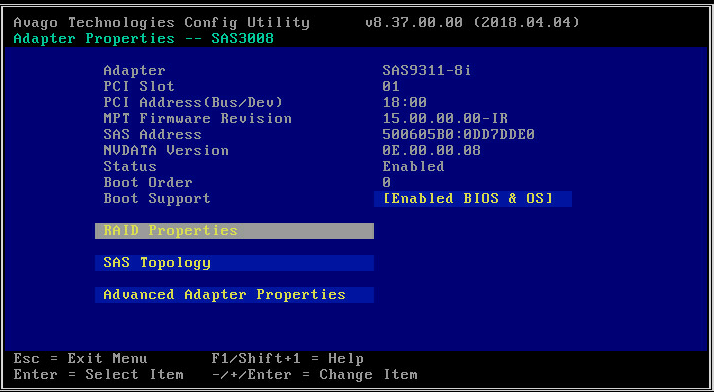
2. On the screen as shown in Figure 73, press Enter.

The controller configuration screen as shown in Figure 74 opens.
Figure 74 Controller configuration screen
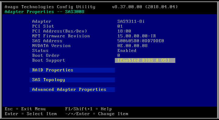
Table 3 Parameter description
|
Parameter |
Description |
|
Adapter |
Storage controller name. |
|
MPT Firmware Revision |
MPT firmware version. |
|
Boot Order |
Boot order for multiple storage controllers. If only one storage controller exists, the field displays 0. |
|
Boot Support |
Support for storage controller management. Options include: · Enabled BIOS & OS—RAID array management is supported for both the BIOS and the OS. · Enabled BIOS Only—RAID array management is supported for the BIOS only. · Enabled OS Only—RAID array management is supported for the OS only. · Disabled—RAID array management is not supported for either the BIOS or the OS. |
Configuring a RAID array
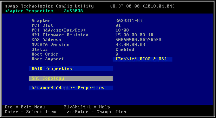
1. On the storage controller configuration screen as shown in Figure 75, select RAID Properties and press Enter.
Figure 75 Storage controller configuration screen

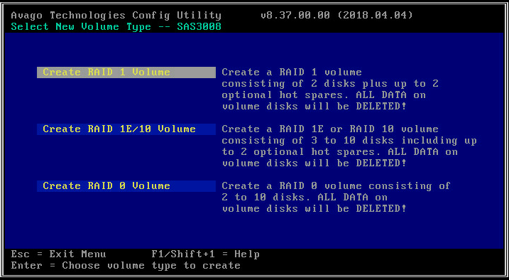
2. On the screen as shown in Figure 76, select a target RAID level and press Enter.
Figure 76 Logical Device Configuration screen
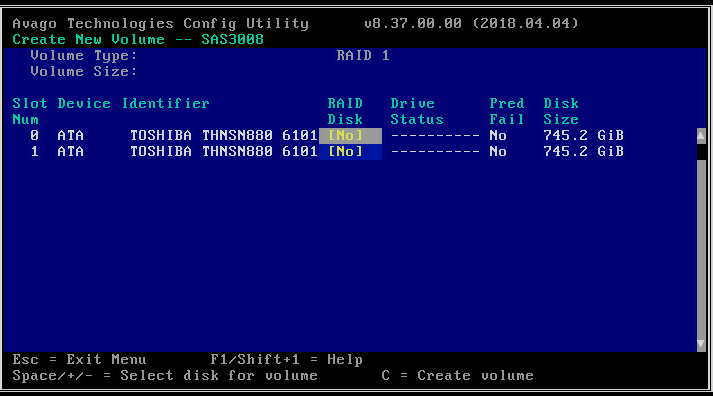
3. On the screen as shown in Figure 77, navigate to a drive, and then press the space bar to select the drive. [Yes] indicates that the drive has been selected for the RAID array. Then, press C.
Figure 77 Selecting the target drives
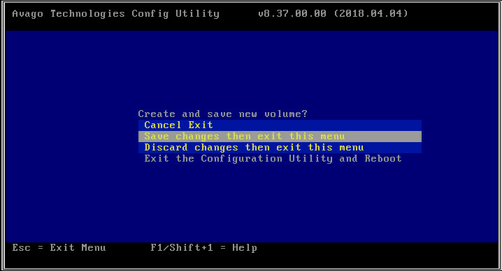
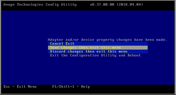
4. On the screen as shown in Figure 78, select Save changes then exit this menu and press Enter.
Figure 78 Save the controller configuration
Configuring hot spare drives
1. On the storage controller configuration screen as shown in Figure 79, select RAID Properties and press Enter.
Figure 79 Storage controller configuration screen
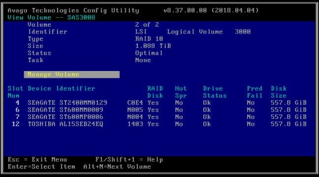
2. On the screen as shown in Figure 80, select Manage Volume and press Enter. For more information about the parameters, see Table 4.
Figure 80 Selecting Manage Volume
|
Parameter |
Description |
|
Volume |
RAID serial number. |
|
Identifier |
RAID identifier. |
|
Type |
RAID level. |
|
Status |
Current RAID status. |
|
Task |
Current RAID task. No background task is in progress for the RAID if this field displays None. |
|
Manage Volume |
You can select this item and press Enter to manage the RAID. |
|
Alt+N |
If two RAID arrays exist, you can press Alt+N to switch the RAID array for information displaying. |
3. On the screen as shown in Figure 81, select Manage Hot Spares and press Enter.
Figure 81 Selecting Manage Hot Spares

4. On the screen as shown in Figure 82, navigate to a drive, and then press the space bar to select the drive. [Yes] indicates that the drive has been selected. Then, press C.
Figure 82 Selecting the target drives

5. On the screen as shown in Figure 83, select Save changes then exit this menu and press Enter.
Figure 83 Saving the controller configuration

Deleting a RAID array
1. On the storage controller configuration screen as shown in Figure 84, select RAID Properties and press Enter.
Figure 84 Storage controller configuration screen

2. On the screen as shown in Table 5, select Manage Volume and press Enter.
Table 5 Selecting Manage Volume

3. On the screen as shown in Figure 85, select Delete Volume, press Enter, and then press Y to delete the array.
Figure 85 Deleting the target array

Running consistency check
This feature enables you to check the consistency and validity of data redundancy for RAID 1, 10, and 1E.
To run consistency check:
1. On the storage controller configuration screen as shown in Figure 86, select RAID Properties and press Enter.
Figure 86 Storage controller configuration screen

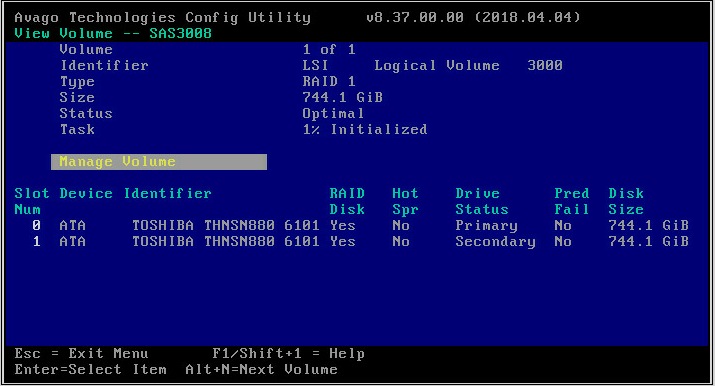
2. On the screen as shown in Figure 87, select Manage Volume and press Enter.
Figure 87 Selecting Manage Volume
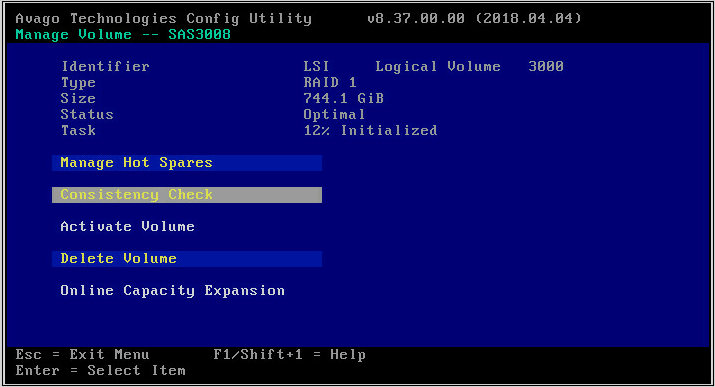
3. On the screen as shown in Table 6, select Consistency Check, press Enter, and then press Y.
Table 6 Selecting Consistency Check
Viewing drive properties
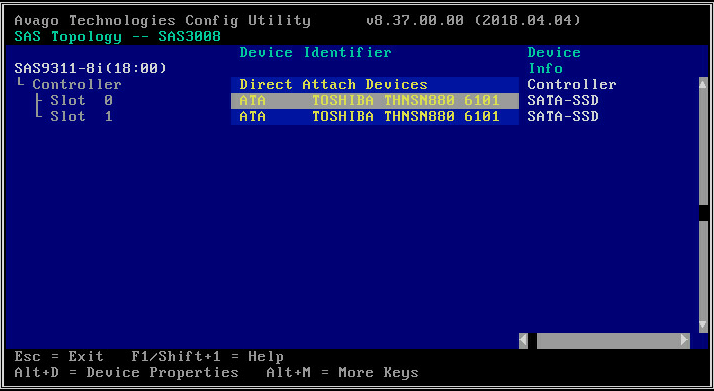
1. On the storage controller configuration screen as shown in Figure 88, select SAS Topology and press Enter.
Figure 88 Storage controller configuration screen

2. On the screen as shown in Figure 89, select the physical drive you want to view and press Alt+D. For more information about the parameters, see Table 7.
Figure 89 Selecting a physical drive

Table 7 SAS Topology parameters
|
Parameter |
Description |
|
Device Info |
Device information. |
|
RAID VOL |
Number of RAID arrays for the controller. A maximum of 2 RAID arrays are supported. The storage controller supports multiple RAID modes. This field varies by RAID level and might display value such as RAID1 VOL or RAID10 VOL. |
|
Alt+D |
Displays the details if you select a drive that is highlighted on the screen. |
|
Alt+M |
Displays more keyboard shortcuts on the SAS Topology screen. |
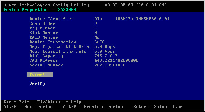
3. View properties of the drive on the screen as shown in Figure 90.

Locating drives
1. On the storage controller configuration screen as shown in Figure 91, select SAS Topology and press Enter.
Figure 91 Storage controller configuration screen

2. On the screen as shown in Figure 92, select the physical drive you want to locate and press Enter to turn on the drive LED on the drive backplane.
Figure 92 Selecting a physical drive
Clearing RAID information or verifying drives
1. On the storage controller configuration screen as shown in Figure 93, select SAS Topology and press Enter.
Figure 93 Storage controller configuration screen

2. On the screen as shown in Figure 94, select the physical drive you want to locate and press Alt+D.
Figure 94 Selecting a physical drive

3. On the screen as shown in Figure 95, select Verify or Format as needed, and then press Enter.
Figure 95 Verifying or formatting the physical drive
Setting advanced controller properties
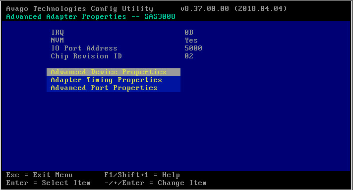
1. On the storage controller configuration screen as shown in Figure 96, select Advanced Adapter Properties and press Enter.
Figure 96 Storage controller configuration screen

2. On the screen as shown in Figure 97, select Advanced Device Properties and press Enter.
Figure 97 Selecting Advanced Device Properties
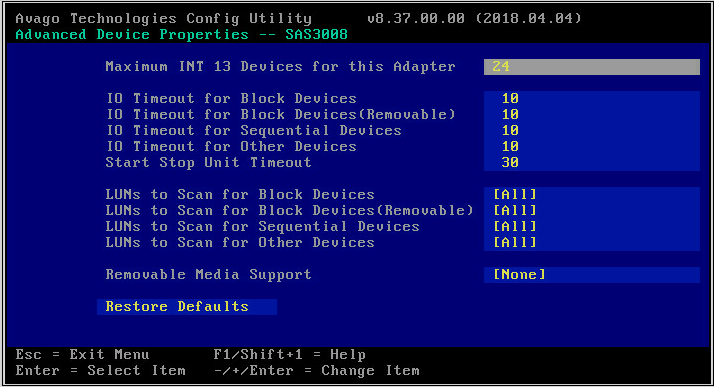
3. Change the advanced properties of the controller on the screen as shown in Figure 98.
Figure 98 Advanced controller properties screen
4. Keep pressing Esc till you enter the screen as shown in Figure 99. Select Save changes then exit this menu and press Enter to save the controller configuration.
The change takes effect at next startup.
Figure 99 Saving the controller configuration
Configuring boot options
1. On the storage controller configuration screen as shown in Figure 100, select SAS Topology and then press Enter.
Figure 100 Storage controller configuration screen
2. On the screen as shown in Figure 101, select the target drive and then press Alt+B to specify the drive as the boot device in legacy mode.
Figure 101 Configuring the boot device

3. To display more keyboard shortcuts on the SAS Topology screen, press Alt+M. For more information about keyboard shortcuts, see Table 8.
Figure 102 Displaying more keyboard shortcuts

Table 8 Keyboard shortcut parameters
|
Parameter |
Description |
|
Alt+A |
Configure or cancel a selected device as the secondary boot option. The key changes to Boot in Device Info if the operation succeeds. |
|
Alt+B |
Configure or cancel a selected device as the first boot option. The key changes to Alt in Device Info if the operation succeeds. |
|
Enter |
· If you select a drive adapter or RAID, press Enter to display collapsed items. · If you select a drive, press Enter to turn on the Fault/UID LED. |
4. To cancel a specified boot device, select the drive and then press Alt+B.
5. Press Esc until you enter the screen as shown in Figure 103, select Save changes then exit this menu and then press Enter to save the configuration.
The boot option configuration takes effect at next startup.
Figure 103 Saving storage controller configuration

Downloading and installing SAS3IRCU
This section introduces the download and installation steps of the OS command line tool. You can use the OS command line tool to manage storage controllers during normal server operation without restarting the server.
Downloading SAS3IRCU
2. Download the installation package and release notes for the corresponding storage controller firmware as instructed.
3. Decompress the installation package to obtain the SAS3IRCU tool package for different operating systems.
Installing SAS3IRCU
See the release notes to install SAS3IRCU for the corresponding operating system.
Commonly-used commands in SAS3IRCU
This section describes the usage and examples of commonly used commands in SAS3IRCU. You can use the OS command line tool to manage storage controllers during normal server operation without restarting the server.
|
|
NOTE: Commands related to the specified path in this tool do not support spaces and special characters. |
Viewing all controllers
Perform this task to view all controllers.
Syntax
sas3ircu list
Examples
# View all controllers.
[root@localhost ~]# ./sas3ircu list
Avago Technologies SAS3 IR Configuration Utility.
Version 17.00.00.00 (2018.04.02)
Copyright (c) 2009-2018 Avago Technologies. All rights reserved.
Adapter Vendor Device SubSys SubSys
Index Type ID ID Pci Address Ven ID Dev ID
----- ------------ ------ ------ ----------------- ------ ------
0 SAS3008 1000h 97h 00h:a1h:00h:00h 1000h 3090h
SAS3IRCU: Utility Completed Successfully.
Viewing detailed controller information
View controller information, including the storage controller name, firmware version, drive slot, capacity, vendor, serial number, interface type, and interface rate.
Syntax
sas3ircu controller_id display
Parameters
controller_id: Specifies the ID of the storage controller.
Examples
# View storage controller information, including the storage controller name, firmware version, and slot number.
[root@localhost ~]# ./sas3ircu 0 display
Avago Technologies SAS3 IR Configuration Utility.
Version 17.00.00.00 (2018.04.02)
Copyright (c) 2009-2018 Avago Technologies. All rights reserved.
Read configuration has been initiated for controller 0
------------------------------------------------------------------------
Controller information
------------------------------------------------------------------------
Controller type : SAS3008
BIOS version : 8.37.01.01
Firmware version : 16.00.10.00
Channel description : 1 Serial Attached SCSI
Initiator ID : 0
Maximum physical devices : 255
Concurrent commands supported : 4096
Slot : 7
Segment : 0
Bus : 161
Device : 0
Function : 0
RAID Support : Yes
------------------------------------------------------------------------
IR Volume information
------------------------------------------------------------------------
------------------------------------------------------------------------
Physical device information
------------------------------------------------------------------------
Initiator at ID #0
# View detailed drive information.
Device is a Hard disk
Enclosure # : 2
Slot # : 0
SAS Address : 578aa82-c-b6d2-0000
State : Ready (RDY)
Size (in MB)/(in sectors) : 11444223/23437770751
Manufacturer : ATA
Model Number : ST12000NM001G-2M
Firmware Revision : SN03
Serial No : ZLW028VH
Unit Serial No(VPD) : ZLW028VH
GUID : 5000c500c4283e28
Protocol : SATA
Drive Type : SATA_HDD
Upgrading the storage controller firmware
Perform this task to upgrade the firmware of a storage controller.
Syntax
To obtain storage controller IDs: sas3flash –listall
To upgrade the storage controller firmware: sas3flash.efi -c controller_id -o -f x.bin
To upgrade the Legacy BIOS driver: sas3flash -o -b y.rom
To upgrade the UEFI BIOS driver: sas3flash -o -b z.rom
Parameters
x.bin: Specifies the name of the storage controller firmware.
controller_id: Specifies the ID of the storage controller.
y.rom: Specifies the name of the Legacy BIOS driver file.
z.rom: Specifies the name of the UEFI BIOS driver file.
Usage guidelines
· When upgrading the storage controller firmware, you must also upgrade the corresponding Legacy BIOS driver or UEFI BIOS driver.
· When upgrading the firmware of a single storage controller, the -c controller_id option is not required.
Examples
# View controller IDs.
[root@localhost home]# ./sas3flash -listall
Avago Technologies SAS3 Flash Utility
Version 16.00.00.00 (2017.05.02)
Copyright 2008-2017 Avago Technologies. All rights reserved.
Adapter Selected is a Avago SAS: SAS3008(C0)
Num Ctlr FW Ver NVDATA x86-BIOS PCI Addr
----------------------------------------------------------------------------
0 SAS3008(C0) 15.00.00.00 0e.00.00.08 08.35.04.00 00:af:00:00
Finished Processing Commands Successfully.
Exiting SAS3Flash.
# Upgrade the storage controller firmware.
[root@localhost ~]# ./sas3flash -o -f 9311_P1616_OOB_20210529.bin
Avago Technologies SAS3 Flash Utility
Version 17.00.00.00 (2018.04.02)
Copyright 2008-2018 Avago Technologies. All rights reserved.
Advanced Mode Set
Adapter Selected is a Avago SAS: SAS3008(C0)
Executing Operation: Flash Firmware Image
Firmware Image has a Valid Checksum.
Firmware Version 16.00.16.00
Firmware Image compatible with Controller.
Valid NVDATA Image found.
NVDATA Major Version 0e.01
Checking for a compatible NVData image...
NVDATA Device ID and Chip Revision match verified.
NVDATA Versions Compatible.
Valid Initialization Image verified.
Valid BootLoader Image verified.
Beginning Firmware Download...
Firmware Download Successful.
Verifying Download...
Firmware Flash Successful.
Resetting Adapter...
Adapter Successfully Reset.
NVDATA Version 0e.01.00.0c
Finished Processing Commands Successfully.
Exiting SAS3Flash.
Locating physical drives
Perform this task to turn on or turn off the UID LEDs for physical drives.
Syntax
ssas3ircu controller_id locate enclosure_id:slot_id operation
Parameters
controller_id: Specifies the ID of the storage controller.
enclosure_id: Specifies the enclosure ID.
slot_id: Specifies the ID of the drive slot.
operation: Specifies the action to take. Options include:
· on: Turn on the drive UID LED.
· off: Turn off the drive UID LED.
Examples
# Turn on the drive UID LED.
[root@localhost ~]# ./sas3ircu 0 locate 2:3 on
Avago Technologies SAS3 IR Configuration Utility.
Version 17.00.00.00 (2018.04.02)
Copyright (c) 2009-2018 Avago Technologies. All rights reserved.
SAS3IRCU: LOCATE command completed successfully.
SAS3IRCU: Command LOCATE Completed Successfully.
SAS3IRCU: Utility Completed Successfully.
# Turn off the drive UID LED.
[root@localhost ~]# ./sas3ircu 0 locate 2:3 off
Avago Technologies SAS3 IR Configuration Utility.
Version 17.00.00.00 (2018.04.02)
Copyright (c) 2009-2018 Avago Technologies. All rights reserved.
SAS3IRCU: LOCATE command completed successfully.
SAS3IRCU: Command LOCATE Completed Successfully.
SAS3IRCU: Utility Completed Successfully.
Creating and deleting RAID arrays
Perform this task to create and delete RAID arrays.
Syntax
sas3ircu controller_id create RAIDlevel capacity enclosure_id:slot_id name noprompt
sas3ircu controller_id delete noprompt
Parameters
controller_id: Specifies the ID of the storage controller.
level: Specifies the RAID level.
capacity: Specifies the capacity of the RAI array.
enclosure_id: Specifies the enclosure ID.
slot_id: Specifies the ID of the drive slot.
name: Specifies the name of the RAID array.
Examples
# Create an RAID array.
[root@localhost ~]# ./sas3ircu 0 create RAID1 MAX 2:0 2:1 Test01 noprompt
Avago Technologies SAS3 IR Configuration Utility.
Version 17.00.00.00 (2018.04.02)
Copyright (c) 2009-2018 Avago Technologies. All rights reserved.
Please wait, may take up to a minute...
SAS3IRCU: Volume created successfully.
SAS3IRCU: Command CREATE Completed Successfully.
SAS3IRCU: Utility Completed Successfully.
# Delete RAID arrays.
[root@localhost ~]# ./sas3ircu 0 delete noprompt
Avago Technologies SAS3 IR Configuration Utility.
Version 17.00.00.00 (2018.04.02)
Copyright (c) 2009-2018 Avago Technologies. All rights reserved.
Please wait, may take up to a minute...
SAS3IRCU: Volume deleted successfully.
SAS3IRCU: Command DELETE Completed Successfully.
SAS3IRCU: Utility Completed Successfully.
Deleting a specific RAID array
Perform this task to delete a specific RAID array.
Syntax
sas3ircu controller_id deletevolume volume_id noprompt
Parameters
controller_id: Specifies the ID of the storage controller.
volume_id: Specifies the RAID array ID.
Examples
# Delete the RAID array with ID 286.
[root@localhost ~]# ./sas3ircu 0 deletevolume 286 noprompt
Avago Technologies SAS3 IR Configuration Utility.
Version 17.00.00.00 (2018.04.02)
Copyright (c) 2009-2018 Avago Technologies. All rights reserved.
Please wait, may take up to a minute...
SAS3IRCU: Volume deleted successfully.
SAS3IRCU: Command DELETEVOLUME Completed Successfully.
SAS3IRCU: Utility Completed Successfully.
Creating and deleting a hot spare drive
Perform this task to create and delete a hot spare drive.
Syntax
sas3ircu controller_id hotspare enclosure_id:slot_id
sas3ircu controller_id hotspare delete enclosure_id:slot_id
Parameters
controller_id: Specifies the ID of the storage controller.
enclosure_id: Specifies the enclosure ID.
slot_id: Specifies the ID of the drive slot.
Examples
# Create a hot spare drive.
[root@localhost ~]# ./sas3ircu 0 hotspare 2:3
Avago Technologies SAS3 IR Configuration Utility.
Version 17.00.00.00 (2018.04.02)
Copyright (c) 2009-2018 Avago Technologies. All rights reserved.
WARNING: Proceeding with this operation may cause data loss or data
corruption. Are you sure you want to proceed (YES/NO)? yes
WARNING: This is your last chance to abort this operation. Do you wish
to abort (YES/NO)? no
Please wait, may take up to a minute...
SAS3IRCU: Hot Spare disk created successfully.
SAS3IRCU: Command HOTSPARE Completed Successfully.
SAS3IRCU: Utility Completed Successfully.
# Delete a hot spare drive.
[root@localhost ~]# ./sas3ircu 0 hotspare delete 2:3
Avago Technologies SAS3 IR Configuration Utility.
Version 17.00.00.00 (2018.04.02)
Copyright (c) 2009-2018 Avago Technologies. All rights reserved.
WARNING: Proceeding with this operation may cause data loss or data
corruption. Are you sure you want to proceed (YES/NO)? yes
WARNING: This is your last chance to abort this operation. Do you wish
to abort (YES/NO)? no
SAS3IRCU: Hot Spare disk deleted successfully.
SAS3IRCU: Command HOTSPARE Completed Successfully.
SAS3IRCU: Utility Completed Successfully.
Viewing virtual drive status
Perform this task to view virtual drive status.
Syntax
sas3ircu controller_id status
Parameters
controller_id: Specifies the ID of the storage controller.
Examples
[root@localhost ~]# ./sas3ircu 0 status
Avago Technologies SAS3 IR Configuration Utility.
Version 17.00.00.00 (2018.04.02)
Copyright (c) 2009-2018 Avago Technologies. All rights reserved.
Background command progress status for controller 0...
IR Volume 1
Volume ID : 286
Current operation : Background Init
Volume status : Enabled
Volume state : Optimal
Volume wwid : 0138e0c228461f5c
Physical disk I/Os : Not quiesced
Volume size (in sectors) : 15626952704
Number of remaining sectors : 14596466944
Percentage complete : 6.59%
SAS3IRCU: Command STATUS Completed Successfully.
SAS3IRCU: Utility Completed Successfully.
Activating an RAID array
Perform this task to activate an RAID array.
Syntax
sas3ircu controller_id activate volume_id
Parameters
controller_id: Specifies the ID of the storage controller.
volume_id: Specifies the RAID array ID.
Examples
# Activate the RAID array with ID 322.
[root@localhost ~]:~# ./sas3ircu 0 activate 322
Avago Technologies SAS3 IR Configuration Utility.
Version 13.00.00.00 (2016.03.08)
Copyright (c) 2009-2016 Avago Technologies. All rights reserved.
SAS3IRCU: ACTIVATE Volume 322 Passed!
SAS3IRCU: Command ACTIVATE Completed Successfully.
SAS3IRCU: Utility Completed Successfully.
Collecting and clearing RAID array event logs
Perform this task to collect and clear RAID array event logs.
Syntax
sas3ircu controller_id logir upload name
sas3ircu controller_id logir clear
Parameters
controller_id: Specifies the ID of the storage controller.
logfilename: Specifies the log file name.
Examples
# Collect RAID array event logs and save them to a local file named FW.log.
[root@localhost ~]# ./sas3ircu 0 logir upload FW.log
Avago Technologies SAS3 IR Configuration Utility.
Version 17.00.00.00 (2018.04.02)
Copyright (c) 2009-2018 Avago Technologies. All rights reserved.
SAS3IRCU: LogIR command successful.
SAS3IRCU: Command LOGIR Completed Successfully.
SAS3IRCU: Utility Completed Successfully.
# Clear RAID array event logs.
[root@localhost ~]# ./sas3ircu 0 logir clear
Avago Technologies SAS3 IR Configuration Utility.
Version 17.00.00.00 (2018.04.02)
Copyright (c) 2009-2018 Avago Technologies. All rights reserved.
WARNING: Proceeding with this operation will erase all log information
stored in the controller. Are you sure you want to proceed (YES/NO)? yes
SAS3IRCU: LogIR command successful.
SAS3IRCU: Command LOGIR Completed Successfully.
SAS3IRCU: Utility Completed Successfully.
Troubleshooting
For detailed information about collecting storage controller fault information, diagnosing and locating faults, and troubleshooting servers, see H3C Servers Troubleshooting Guide.
Compatibility
For information about storage controller and server compatibility, access http://www.h3c.com/en/home/qr/default.htm?id=66.
Downloading and installing drivers
Access the H3C official website to download the storage controller drivers. For more information about installing drivers, see the release notes for the driver program.
