- Table of Contents
-
- 03-Layer 2—LAN Switching Configuration Guide
- 00-Preface
- 01-Ethernet interface configuration
- 02-Loopback, null, and inloopback interface configuration
- 03-Bulk interface configuration
- 04-MAC address table configuration
- 05-Ethernet link aggregation configuration
- 06-M-LAG configuration
- 07-Port isolation configuration
- 08-VLAN configuration
- 09-MVRP configuration
- 10-QinQ configuration
- 11-VLAN mapping configuration
- 12-Loop detection configuration
- 13-Spanning tree configuration
- 14-LLDP configuration
- 15-L2PT configuration
- 16-PPP configuration
- 17-Service loopback group configuration
- 18-PFC configuration
- Related Documents
-
| Title | Size | Download |
|---|---|---|
| 18-PFC configuration | 67.77 KB |
Contents
Configuring PFC deadlock detection
Configuring the early warning thresholds for PFC packets
Configuring PFC
About PFC
Priority-based flow control (PFC) provides a finer flow control mechanism to implement lossless packet transmission on Ethernet.
PFC performs flow control for packets based on the 802.1p priorities carried in packets. As shown in Figure 1, PFC establishes eight virtual channels over an Ethernet link, each corresponding to an 802.1p priority. Any virtual channel can be paused or restarted independent of the other channels. This mechanism allows multiple types of traffic to coexist on and share an Ethernet link.
Figure 1 How PFC works
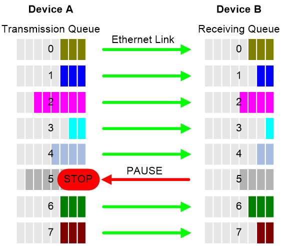
When congestion occurs on the local end, the device determines how to process received packets based on the 802.1p priorities carried in packets as follows:
· If PFC is enabled for the 802.1p priority carried in a packet, the local end accepts the packet and sends PFC pause frames to notify the remote end to stop sending packets carrying the 802.1p priority. The remote end stops sending packets carrying the 802.1p priority after receiving the PFC pause frames. This process is repeated until congestion is eliminated.
· If PFC is not enabled for the 802.1p priority carried in a packet, the local end drops the packet.
Restrictions and guidelines
You can configure PFC in system view or Ethernet interface view. When you configure PFC in system view and Ethernet interface view multiple times, the most recent configuration takes effect.
If you do not enable PFC on an interface, the interface can receive but cannot process PFC pause frames. To make PFC take effect, you must enable PFC on both ends.
To avoid packet loss, apply the same PFC configuration to all interfaces that the packets pass through.
In an IRF network, follow these restrictions and guidelines:
· For IRF and other protocols to operate correctly, as a best practice, do not enable PFC for 802.1p priority 0, 6, or 7.
· To perform PFC on an IRF port, configure PFC on the IRF port and the IRF physical ports that are bound to the IRF port.
For information about IRF, see IRF configuration Guide.
For PFC to take effect in an overlay network, execute the qos trust tunnel-dot1p command. For information about the overlay network, see VXLAN Configuration Guide. For information about the qos trust tunnel-dot1p command, see ACL and QoS Command Reference.
Configuring PFC on interfaces
1. Enter system view.
system-view
2. Enable PFC on all Ethernet interfaces.
priority-flow-control { auto | enable }
By default, PFC is disabled on all Ethernet interfaces.
3. Enable PFC for 802.1p priorities on all Ethernet interfaces.
priority-flow-control no-drop dot1p dot1p-list
By default, PFC is disabled for all 802.1p priorities on all Ethernet interfaces.
4. Enter Ethernet interface view.
interface interface-type interface-number
5. Enable PFC on the Ethernet interface.
priority-flow-control { auto | enable }
By default, PFC is disabled.
6. Enable PFC for 802.1p priorities.
priority-flow-control no-drop dot1p dot1p-list
By default, PFC is disabled for all 802.1p priorities.
Configuring PFC deadlock detection
About this task
When packets carrying the specified 802.1p priority are transmitted in a loop, packets in the data buffer cannot be forwarded and PFC frames are repeatedly transmitted between devices. As a result, the cell resources in the buffer for device interfaces always cannot be released. In this case, the device enters the PFC deadlock state.
This feature periodically detects whether the device is in the PFC deadlock state. If an interface is always in the PFC XOFF state within the PFC deadlock detection interval, the device enters the PFC deadlock state. If PFC deadlock detection is recovered in automatic mode, the device automatically releases the deadlock state and recovers PFC and PFC deadlock detection after the delay timer expires. During the delay timer period, the device disables PFC and PFC deadlock detection on the interface, so that packets can be forwarded properly.
After the PFC deadlock state is released, the PFC deadlock detection feature can be recovered on the interface in automatic or manual mode. Recovering this feature enables the PFC feature again at the same time. Use the automatic recovery mode when no serious failures occur.
When a packet loop cannot be eliminated and the device enters PFC deadlock state frequently, manually recover PFC deadlock detection on the interface as follows:
1. Perform troubleshooting and set the manual recovery mode for PFC deadlock detection.
2. Execute the priority-flow-control deadlock recover command to recover the PFC deadlock detection and PFC features.
Restrictions and guidelines
The specified CoS value must be within the 802.1p priority list specified by using the priority-flow-control no-drop dot1p command. To view the 802.1p priority for each CoS value, execute the display qos map-table dot1p-lp command.
Prerequisites
Before you configure PFC deadlock detection on an Ethernet interface, complete the following tasks:
· Enable PFC in auto mode or forcibly on the Ethernet interface.
· Enable PFC for 802.1p priorities on the Ethernet interface.
Procedure
1. Enter system view.
system-view
2. Set the precision for the PFC deadlock detection timer.
priority-flow-control deadlock precision { high | normal | low }
By default, the PFC deadlock detection timer uses normal precision.
3. Set the PFC deadlock detection interval for the specified CoS value.
priority-flow-control deadlock cos cos-value interval interval
By default, the PFC deadlock detection interval is not set.
4. Configure the delay timer for PFC deadlock detection automatic recovery.
priority-flow-control deadlock auto-recover cos cos-value delay delay-time
By default, the delay timer for PFC deadlock detection automatic recovery is not configured.
5. Configure the action to take on packets during the delay timer period for PFC deadlock automatic recovery.
priority-flow-control deadlock auto-recover action { discard | forwarding }
By default, the device forwards received data packets during the delay timer period for PFC deadlock detection automatic recovery.
6. Configure the upper threshold for PFC deadlock times during the specified period.
priority-flow-control deadlock threshold cos cos-value period period count count [ error-down ]
By default, the upper threshold for PFC deadlock times during the specified period is not configured.
7. Enter Ethernet interface view.
interface interface-type interface-number
8. Set the recovery mode for PFC deadlock detection on the Ethernet interface.
priority-flow-control deadlock recover-mode { auto | manual }
By default, PFC deadlock detection recovers in automatic mode.
9. Enable PFC deadlock detection on the Ethernet interface.
priority-flow-control deadlock enable
By default, PFC deadlock detection is disabled.
10. (Optional.) Recover PFC deadlock detection on the Ethernet interface.
priority-flow-control deadlock recover
You can use only this command to recover PFC deadlock detection if you set the manual recovery mode for PFC deadlock detection on the Ethernet interface.
Configuring the early warning thresholds for PFC packets
About this task
You can configure the early warning threshold for incoming or outgoing PFC packets of an interface as needed. The early warning threshold notifies a situation where the PFC packet transmission rate is still within a normal range but needs attention.
When the rate of PFC packets that an interface sends or receives reaches the early warning threshold, the system generates traps and logs to notify the user. According to the traps and logs, the user can discover some exceptions in the network, for example:
· The NIC of the peer device fails and continuously sends PFC packets at a high speed. In this case, you can set the early warning threshold for incoming PFC packets.
· The device fails and continuously sends PFC frames. In this case, you can set the early warning threshold for outgoing PFC packets.
To monitor bidirectional PFC packets, you can set the early warning thresholds for incoming packets and outgoing packets separately.
Restrictions and guidelines
The number of PFC pause frames that an interface sends or receives is counted and the early warning threshold configuration takes effect only when PFC is enabled.
Procedure
1. Enter system view.
system-view
2. Enter Ethernet interface view.
interface interface-type interface-number
3. Configure the early warning threshold for incoming PFC packets.
priority-flow-control early-warning dot1p dot1p-list inpps pps-value
By default, no early warning threshold is configured for incoming PFC packets.
4. Configure the early warning threshold for outgoing PFC packets.
priority-flow-control early-warning dot1p dot1p-list outpps pps-value
By default, no early warning threshold is configured for outgoing PFC packets.
Verifying and maintaining PFC
Execute display commands in any view.
|
Task |
Command |
|
Display the PFC information of interfaces. |
display priority-flow-control interface [ interface-type [ interface-number ] ] |
