- Table of Contents
-
- 07-Layer 3—IP Routing Configuration Guide
- 00-Preface
- 01-Basic IP routing configuration
- 02-Static routing configuration
- 03-RIP configuration
- 04-OSPF configuration
- 05-IS-IS configuration
- 06-EIGRP configuration
- 07-BGP configuration
- 08-Policy-based routing configuration
- 09-IPv6 static routing configuration
- 10-RIPng configuration
- 11-OSPFv3 configuration
- 12-IPv6 policy-based routing configuration
- 13-Routing policy configuration
- 14-DCN configuration
- Related Documents
-
| Title | Size | Download |
|---|---|---|
| 06-EIGRP configuration | 295.64 KB |
Contents
EIGRP packet types and transmission modes
Configuring EIGRP route control
Enabling automatic route summarization
Configuring route redistribution
Configuring EIGRP route preferences
Configuring discard route preferences
Setting the maximum number of EIGRP ECMP routes
Configuring metrics for an interface
Tuning and optimizing EIGRP networks
Setting the convergence wait timer
Setting the DSCP value for EIGRP packets
Setting the aging timer for routes on a GR helper
Display and maintenance commands for EIGRP
Example: Configuring basic EIGRP
Example: Configuring EIGRP interface metrics
Example: Configuring EIGRP route redistribution
Example: Configuring EIGRP route summarization
EIGRP neighbor relationship cannot be established
Configuring EIGRP
About EIGRP
The Enhanced Interior Gateway Routing Protocol (EIGRP) is a routing protocol based on distance-vector technology.
EIGRP characteristics
EIGRP has the following characteristics:
· Multiprocess—EIGRP supports multiple processes running on the same system. Each EIGRP process is uniquely identified by an autonomous system (AS) number. You can enable route redistribution between different EIGRP processes. The AS numbers for EIGRP processes are carried in the EIGRP protocol packets. You can create multiple processes for an interface.
· Triggered updates and partial updates—EIGRP sends only incremental updates to affected neighbors upon route changes to reduce network bandwidth consumption.
· Increased network width—The use of large route metrics makes EIGRP applicable to large-scale networks.
· Fast loop-free convergence—EIGRP uses the Diffusing Update Algorithm (DUAL) to process received routing information and calculate the optimal route for destination networks. DUAL achieves fast loop-free convergence with reduced complexity and overhead. Only the routes and routers affected by a topology change are involved in route calculation.
EIGRP packet types and transmission modes
EIGRP uses the Reliable Transport Protocol (RTP) to manage packet exchange. RTP has the following packet transmission modes:
· Reliable transmission mode—Sends EIGRP packets orderly with non-zero sequence numbers that require acknowledgments. The sender does not send any new packet until it receives the acknowledgement for the previous packet. A packet that is not acknowledged will be retransmitted.
· Unreliable transmission mode—Sends EIGRP packets with a sequence number of 0 that do not require acknowledgments.
EIGRP packets are encapsulated in IP packets. The protocol number for EIGRP is 88.
RTP includes the following packet types:
· Hello—Used for neighbor discovery and maintenance. EIGRP periodically sends multicast Hello packets in unreliable transmission mode.
· ACK—Used for acknowledging reliably received packets. EIGRP sends unicast acknowledgments in unreliable transmission mode.
· Query and Reply—Query packets are sent to neighbors in multicast to request path information for destination networks. Reply packets are sent in unicast to respond to Query packets. EIGRP sends Query and Reply packets in reliable transmission mode.
· SIA-Query and SIA-Reply—SIA-Query packets are sent to neighbors to determine if the convergence is still ongoing for specific routes. SIA-Reply packets are sent in response to SIA-Query packets. EIGRP sends unicast SIA-Query and SIA-Reply packets in reliable transmission mode.
· Update—Used for exchanging routing information between EIGRP neighbors. When establishing neighborship for the first time, a router sends Update packets in unicast containing all local routing information to its neighbors. After that, the router sends Update packets in multicast to all neighbors upon route changes. EIGRP sends Update packets in reliable transmission mode.
· Request—Originally designed for use by route servers, and not in use in the current software version.
EIGRP metrics
EIGRP calculates the composite route metric based on the following metrics:
· Bandwidth—Minimum interface bandwidth on the path from the local router to the destination network.
· Delay—Sum of all interface delays on the path from the local router to the destination network.
· Reliability—Minimum interface reliability value on the path from the local router to the destination network.
· Load—Maximum interface load value on the path from the local router to the destination network.
· MTU—Minimum interface MTU on the path from the local router to the destination network.
EIGRP assigns each metric a weight for calculating the composite route metric. The calculation formula uses coefficients (K values) that correspond to the metrics as follows:
· K1—Bandwidth.
· K2—Load.
· K3—Delay.
· K4—Reliability.
· K5—MTU.
EIGRP calculates the composite route metric as follows:
· If K5 is equal to 0, the following formula applies:
Metric 1 = 256 × [K1 × Bandwidth + (K2 × Bandwidth) / (256 - Load) + K3 × Delay]
· If K5 is not equal to 0, Metric 1 is multiplied by another coefficient as follows:
Metric 2 = Metric 1 × [K5 / (Reliability + K4)]
In the formula: Bandwidth = 10000000 / Minimum interface bandwidth on the path.
Figure 1 EIGRP composite route metric calculation
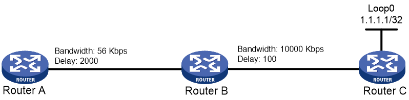
As shown in Figure 1, for Path A (between Router A and Router B), the bandwidth is 56 Kbps, and the delay is 2000 (in 10 microseconds). For Path B (between Router B and Router C), the bandwidth is 10000 Kbps, and the delay is 100 (in 10 microseconds). The values for K1 through K5 are 1, 0, 1, 0, and 0, respectively. For a given destination network 1.1.1.1/32, EIGRP calculates the composite metric as follows:
· For Path A, the metric = 256 × (10000000 / 56 + 2000) = 46226285.
· For Path B, the metric = 256 × (10000000 / 10000 + 100) = 281600.
· For the entire path (Path A + Path B), the metric = 256 × [10000000/56 + (2000 + 100)] = 46251885.
The calculation result shows that the metric for the entire path is not calculated by simply summing the metrics for Path A and Path B. For simplicity purposes, the following sections illustrate route metric calculation by simply summing separate path metrics.
EIGRP topology table
EIGRP stores path information advertised by neighbors in the topology table and selects optimal routes from the table.
The EIGRP topology table includes the following information:
· Destination network address.
· FD—Feasible Distance, that is, the lowest metric to the destination network.
· CD—Computed Distance, that is, the total metric along the path to the destination network.
· Path information advertised by neighbors, including:
¡ Neighbor address and the interface where the neighbor resides.
¡ RD—Reported Distance, that is, the metric to the destination network advertised by the neighbor.
· Route state—Passive or Active.
¡ Passive—A route is in Passive state when at least one neighbor that provides the lowest-total-metric path matches the Feasibility Condition (FC). The neighbor matches the FC if it advertises an RD that is lower than the FD computed by the local router. A route in Passive state can be used to forward traffic, and the router does not perform any recalculation.
¡ Active—A route is in Active state when the neighbors that provide the lowest-total-metric path do not match the FC. A route in Active state cannot be used to forward traffic, and the router must communicate with its neighbors to calculate a new lowest-metric, loop-free path for the destination.
· FS—A neighbor becomes a feasible successor if it advertises an RD matching the FC. The route through an FS to the destination network is guaranteed to be loop free, but might not be optimal.
· Successor—A neighbor becomes a successor if it provides the lowest-total-metric path to the destination network.
Figure 2 illustrates how EIGRP selects feasible successors and successors for every destination network in the topology table.
Figure 2 EIGRP successor selection
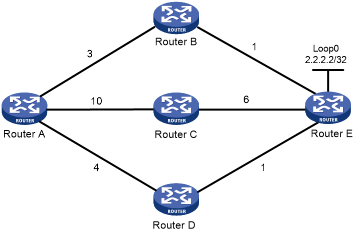
As shown in Figure 2, Router A has three paths to reach the destination network 2.2.2.2/32. The path metrics are represented by numbers for simplicity purposes. By simply summing up all the separate metrics for every path, Router A calculates the following CD values:
· A CD value of 4 for Path A (through Router B).
· A CD value of 16 for Path B (through Router C).
· A CD value of 5 for Path C (through Router D).
Because Path A has the lowest CD value, Router B becomes the successor for the destination network, and the FD value is 4. Router D provides an RD value of 1 that is lower than the FD value, so Router D becomes a feasible successor for Router A.
EIGRP operating mechanism
EIGRP operates as follows:
1. Establishes neighbor relationship. After you enable EIGRP, the router sends Hello packets to the multicast address 224.0.0.10. The receiving router compares the local AS numbers and K-values with those in the Hello packets. If they match, a neighbor relationship is established.
2. Discovers network topology and selects shortest paths. After neighborship establishment, the router sends the routes in the local topology table through Update packets to its neighbors. The neighbors store the received routes into their topology tables and then calculate the optimal routes based on the routing information.
3. Maintains neighbor relationship by periodically sending Hello packets.
4. Updates and queries routes. If a route changes and the current successor becomes invalid, the router searches the topology table for an available FS providing the lowest-total-metric path to the destination. If such an FS is found, the router uses the associated path to forward traffic, and sends Update packets to advertise the route change to the neighbors. If no FS is found or no FS can provide the lowest-total-metric path, the router sends Query packets to its neighbors to search for routes to the destination.
EIGRP route calculation
EIGRP uses DUAL to perform route calculation and ensure route convergence. When the router detects a network change (caused by a state or cost change of the associated link or by reception of an Update packet), it performs the following operations:
· Calculates the total metric for all paths that reach the destination network of the affected route.
· Selects the path with the lowest CD value.
· Checks whether the selected path matches the FC.
If the path matches the FC, the advertising neighbor becomes the successor, and the CD value of the path is used as the FD. If the new FD is different from that of the original route, the router sends Update packets to all neighbors.
If the path does not match the FC, the affected route in the topology table enters the Active state. The router sends Query packets to all neighbors and performs diffusing computation to search for another route to the destination network. Upon receiving the Query packet, the neighbor router performs local computation and processes the query as follows:
¡ If the queried route is in Passive state, the router checks whether the associated path matches the FC. If the path matches the FC, the router selects the best FS and sends a Reply packet to the querier. If the path does not match the FC, the router sets the route to the Active state in the topology table and stops processing the query. The router starts to send Query packets to all its neighbors. When the route is converged and enters the Passive state again, the router sends a Reply packet to the querier.
¡ If the queried route is in Active state, the router checks whether the querier is the successor that is currently used by the route. If the querier is not the successor, the router sends a Reply packet to the querier. If the querier is the successor, the router stops processing the query and starts to send Query packets to all its neighbors. When the route is converged and enters the Passive state again, the router sends a Reply packet to the querier.
After starting a query, the router does not change the successor, FD, or metric (advertised to neighbors) for the queried route before receiving Reply packets from all neighbors. After receiving replies from all neighbors, the EIGRP router performs FC check for the neighbor providing the lowest-total-metric path associated with the route. If the neighbor passes the check, the route is converged and enters the Passive state. If the neighbor fails the check, the router starts another query and performs diffusing computation until the route is converged.
Figure 3 EIGRP route calculation when links are normal
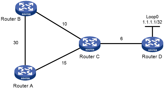
As shown in Figure 3, the metric is 30 for path Router A–Router B, 10 for path Router B–Router C, 15 for path Router A–Router C, and 6 for path Router C–Router D. For a given destination network 1.1.1.1/32, the following conditions exist:
· For Router A, the shortest path to the destination network is Router A–>Router C–>Router D, with a metric of 21, Router C as the successor, and an FD of 21.
· For Router B, the shortest path to the destination network is Router B–>Router C–>Router D, with a metric of 16, Router C as the successor, and an FD of 16.
· For Router C, the shortest path to the destination network is Router C–>Router D, with a metric of 6, Router D as the successor, and an FD of 6.
· For Router A, Router B advertises an RD of 16, which is smaller than the FD. Router B becomes the FS for the destination network.
· For Router B, Router A advertises an RD of 21, which is greater than the FD. Router A cannot be the FS for the destination network.
Figure 4 EIGRP route calculation when a link is broken
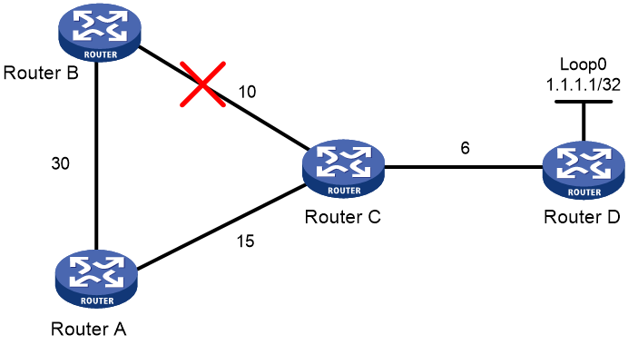
As shown in Figure 4, when the path Router B–Router C is broken, the available shortest path from Router B to the destination network is Router B–>Router A–>Router C–>Router D. Router A does not match the FC because it advertises an RD of 21 (greater than the FD 16 for the original path). Another route must be selected as follows:
1. Router B sets the original route to Active state in the topology table, and sends a Query packet to Router A.
2. Upon receiving the Query packet, Router A checks its topology table. Finding that it has a successor Router C and the route is in Passive state, Router A immediately sends a Reply packet to advertise the route to Router B.
3. After receiving the Reply packet (which means all Reply packets are received in this example), Router B performs route recalculation. The route, with a CD of 41 and Router A as the successor, is converged on Router B and enters the Passive state.
EIGRP SIA state
Typically, a router can receive all replies for the sent Query packets within a short period of time. If the router fails to receive all replies with the specified time, the route being queried gets stuck in the active (SIA) state and fails to be converged. This is more likely to happen in networks where large numbers of low-bandwidth weak links exist.
To prevent a route from being stuck in active for a long time, EIGRP starts a convergence wait timer and sends SIA packets as follows:
1. When sending Query packets, the router starts a convergence wait timer at the same time.
2. When half of the convergence wait time has passed, the router sends SIA-Query packets to the neighbors that have not responded. If these neighbors have not completed route convergence, they send SIA-Reply packets to the querier.
3. Upon receiving the SIA-Reply packets, the router determines that the neighbors are performing diffusing computation, resets the convergence wait timer, and repeats step 2.
4. The router determines that a neighbor is invalid (replies with an infinite metric) and deletes it if one of the following conditions exists:
¡ No SIA-Reply packet is received from the neighbor for the sent SIA-Query packet upon expiration of the convergence wait timer.
¡ No SIA-Reply packet is received from the neighbor for three consecutive SIA-Query packets.
Protocols and standards
RFC 7868, Cisco's Enhanced Interior Gateway Routing Protocol
EIGRP tasks at a glance
To configure EIGRP, perform the following tasks:
¡ (Optional.) Configuring router IDs
2. (Optional.) Configuring EIGRP route control
¡ Enabling automatic route summarization
¡ Configuring route redistribution
¡ Configuring EIGRP route preferences
¡ Configuring discard route preferences
¡ Setting the maximum number of EIGRP ECMP routes
3. (Optional.) Configuring EIGRP metrics
¡ Configuring metrics for an interface
4. (Optional.) Tuning and optimizing EIGRP networks
¡ Setting the convergence wait timer
¡ Setting the DSCP value for EIGRP packets
¡ Setting the aging timer for routes on a GR helper
Configuring basic EIGRP
Enabling EIGRP
About this task
This task allows you to enable EIGRP for a network. After that, only the interface attached to the network runs EIGRP.
Restrictions and guidelines
If you configure EIGRP settings in interface view before enabling EIGRP, the settings do not take effect until EIGRP is enabled.
You cannot enable multiple EIGRP processes on a physical interface.
You can advertise a network to different EIGRP processes.
Procedure
1. Enter system view.
system-view
2. Create an EIGRP process and enter EIGRP view.
eigrp [ eigrp-as ] [ vpn-instance vpn-instance-name ]
By default, no EIGRP process is created.
3. Create the EIGRP IPv4 address family and enter EIGRP IPv4 address family view.
address-family ipv4
4. Enable EIGRP on a network.
network network-address [ wildcard-mask ]
By default, EIGRP is disabled on a network.
Configuring router IDs
About this task
EIGRP uses a router ID to uniquely identify an advertising router in an autonomous system. If a router receives a route containing the router ID of the local router, it discards the route.
If no router ID is configured for an EIGRP process, the process uses the global router ID. If no global router ID is configured, the highest loopback interface IP address, if any, is used as the router ID. If no loopback interface IP address is available, the highest physical interface IP address is used, regardless of the interface status (up or down).
Restrictions and guidelines
|
|
CAUTION: Changing the router ID for an EIGRP process will reset the neighbor relationship. |
Make sure a router ID must be unique for each router in an autonomous system. To ensure the uniqueness of a router ID and enhance network availability, specify the IP address of a local interface (loopback interface as a best practice) as the router ID.
The router ID cannot be 0.0.0.0 or 255.255.255.255.
Procedure
1. Enter system view.
system-view
2. (Optional.) Configure the global router ID.
router id router-id
By default, no global router ID is configured.
3. Enter EIGRP view.
eigrp [ eigrp-as ] [ vpn-instance vpn-instance-name ]
4. Enter IPv4 address family view.
address-family ipv4
5. (Optional.) Configure the router ID for the EIGRP process.
router-id router-id
By default, no router ID is configured for an EIGRP process. The global router ID is used.
Configuring EIGRP route control
Enabling automatic route summarization
About this task
Perform this task to summarize contiguous networks into a single network and advertise the network to neighbors. Route summarization reduces the number of exchanged routes and the routing table size, and improves network scalability and router performance. For example, three networks 192.1.1.0/24, 192.1.2.0/24, and 192.1.3.0/24 are available in the routing table. You can enable EIGRP to summarize the three networks into network 192.1.0.0/16, and advertise the summary network to neighbors.
The smallest metric among all specific routes is used as the metric for the summary route.
Restrictions and guidelines
To advertise the specific routes that have been summarized, use the undo summary automatic command.
Procedure
1. Enter system view.
system-view
2. Enter EIGRP view.
eigrp [ eigrp-as ] [ vpn-instance vpn-instance-name ]
3. Enter IPv4 address family view.
address-family ipv4
4. Enable automatic route summarization.
summary automatic
By default, automatic route summarization is disabled.
Enabling split horizon
About this task
Split horizon disables EIGRP from sending routes through the interface where the routes were learned to prevent routing loops between adjacent routers.
Restrictions and guidelines
As a best practice, do not disable split horizon unless it is necessary. On Non-Broadcast Multi-Access (NBMA) networks, such as X.25 where multiple virtual circuits are configured on the primary and secondary interfaces, disable split horizon to ensure correct route advertisement.
Procedure
1. Enter system view.
system-view
2. Enter interface view.
interface interface-type interface-number
3. Enable split horizon.
eigrp eigrp-as split-horizon
By default, split horizon is enabled.
Configuring route redistribution
About this task
Perform this task to enable an EIGRP process to redistribute routes from other EIGRP processes or other routing protocols.
Restrictions and guidelines
Only active routes can be redistributed. To view route state information, use the display ip routing-table protocol command.
Procedure
1. Enter system view.
system-view
2. Enter EIGRP view.
eigrp [ eigrp-as ] [ vpn-instance vpn-instance-name ]
3. Enter IPv4 address family view.
address-family ipv4
4. Enable route redistribution.
¡ Redistribute routes from other EIGRP processes.
import-route eigrp [ eigrp-as | all-as ] [ allow-direct | metric min-bandwidth total-delay reliability load mtu | route-policy route-policy-name ] *
¡ Redistribute routes from BGP.
import-route bgp [ as-number ] [ allow-ibgp | metric min-bandwidth total-delay reliability load mtu | route-policy route-policy-name ] *
¡ Redistribute routes from IS-IS, OSPF, or RIP.
import-route { isis | ospf | rip } [ process-id | all-processes] [ allow-direct | metric min-bandwidth total-delay reliability load mtu | route-policy route-policy-name ] *
¡ Redistribute direct routes, static routes, or user network routes.
import-route { direct | static | unr } [ metric min-bandwidth total-delay reliability load mtu | route-policy route-policy-name ] *
By default, EIGRP does not redistribute routes.
You can set the metric values used for composite route metric calculation in the import-route command. If you do not set the metric values, the settings in the default-metric command apply.
5. (Optional.) Set the metrics for redistributed routes.
default-metric min-bandwidth total-delay reliability load mtu
The default metric values are as follows:
¡ min-bandwidth is 10000 Kbps.
¡ total-delay is 100 microseconds.
¡ reliability is 255.
¡ load is 1.
¡ mtu is 1500 bytes.
Configuring EIGRP route preferences
About this task
Routing protocols each have a default preference. If they find multiple routes destined for the same network, the route found by the routing protocol with the highest preference is selected as the optimal route.
Perform this task to configure the preference for internal routes learned from the same EIGRP process, and for external routes learned from other EIGRP processes or routing protocols.
Procedure
1. Enter system view.
system-view
2. Enter EIGRP view.
eigrp [ eigrp-as ] [ vpn-instance vpn-instance-name ]
3. Enter IPv4 address family view.
address-family ipv4
4. Configure EIGRP route preferences.
preference internal-preference external-preference
By default, the internal route preference is 90, and the external route preference is 170.
Configuring discard route preferences
About this task
Perform this task to configure preferences for discard routes generated from automatic route summarization.
Procedure
1. Enter system view.
system-view
2. Enter EIGRP view.
eigrp [ eigrp-as ] [ vpn-instance vpn-instance-name ]
3. Enter IPv4 address family view.
address-family ipv4
4. Configure discard route preferences.
discard-route { external external-preference | internal internal-preference } *
By default, the preference is 5 for discard routes generated from automatic summarization for both internal and external routes.
Setting the maximum number of EIGRP ECMP routes
About this task
Perform this task to implement load sharing over equal-cost multi-path (ECMP) routes.
Procedure
1. Enter system view.
system-view
2. Enter EIGRP view.
eigrp [ eigrp-as ] [ vpn-instance vpn-instance-name ]
3. Enter IPv4 address family view.
address-family ipv4
4. Set the maximum number of EIGRP ECMP routes.
maximum load-balancing number
By default, the maximum number of EIGRP ECMP routes is 64.
Configuring EIGRP metrics
Configuring metric weights
Restrictions and guidelines
In an autonomous system, the weight for each metric (K value) used for composite route metric calculation must be the same on all EIGRP routers.
Procedure
1. Enter system view.
system-view
2. Enter EIGRP view.
eigrp [ eigrp-as ] [ vpn-instance vpn-instance-name ]
3. Enter IPv4 address family view.
address-family ipv4
4. Configure metric weights.
metric weights K1 K2 K3 K4 K5
By default, the weights for metrics K1 through K5 are 1, 0, 1, 0, and 0, respectively.
Configuring metrics for an interface
About this task
This task allows you to change the metric values for every interface on a path.
Procedure
1. Enter system view.
system-view
2. Enter interface view.
interface interface-type interface-number
3. Configure metrics for the interface.
eigrp eigrp-as metric { bandwidth bandwidth | delay delay | load load | reliability reliability } *
By default, no metric is configured for an interface.
Tuning and optimizing EIGRP networks
Setting EIGRP packet timers
About this task
You can configure the following EIGRP packet timers for an interface:
· Hello timer—Interval for sending Hello packets. It must be identical on EIGRP neighbors.
· Hold timer—Amount of time that a neighbor is considered valid. The router advertises the hold timer to the neighbor. If the neighbor receives no Hello packets from the local router within the hold time, it determines that the neighbor relationship is invalid.
Restrictions and guidelines
As a best practice, set the hold timer to be at least three times the hello timer.
Procedure
1. Enter system view.
system-view
2. Enter interface view.
interface interface-type interface-number
3. Set the hello timer.
eigrp eigrp-as timer hello seconds
By default, the hello timer is 60 seconds for NBMA networks and 5 seconds for other networks.
A smaller hello timer means a faster speed for detecting topology changes, which consumes more system resources. Set an appropriate hello timer based on your network condition.
4. Set the hold timer.
eigrp eigrp-as timer hold seconds
By default, the hold timer is three times the hello timer.
Setting the convergence wait timer
1. Enter system view.
system-view
2. Enter EIGRP view.
eigrp [ eigrp-as ] [ vpn-instance vpn-instance-name ]
3. Enter IPv4 address family view.
address-family ipv4
4. Set the convergence wait timer.
timers active-time { time-limit | disable }
By default, the convergence wait timer is 3 minutes.
The disable keyword means setting no time limit for route convergence. Typically, as a best practice, do not specify this keyword.
Setting the DSCP value for EIGRP packets
About this task
The Differentiated Services Code Point (DSCP) is carried in the ToS field of IP packets for identifying the packet priority. A large DSCP value means a higher priority in packet transmission. This task allows you to modify the DSCP value for EIGRP packets.
Procedure
1. Enter system view.
system-view
2. Enter EIGRP view.
eigrp [ eigrp-as ] [ vpn-instance vpn-instance-name ]
3. Enter IPv4 address family view.
address-family ipv4
4. Set the DSCP value for EIGRP packets.
dscp dscp-value
By default, the DSCP value for EIGRP packets is 48.
Setting the aging timer for routes on a GR helper
About this task
During the graceful restart (GR) process, the GR restarter and GR helper exchange routing information. If route exchange is not completed when the specified aging timer expires, the GR helper (EIGRP router) quits the GR process. The GR helper updates the RIB entries based on the learned EIGRP routes and removes aged RIB entries.
The device can act only as a GR helper.
Procedure
1. Enter system view.
system-view
2. Enter EIGRP view.
eigrp [ eigrp-as ] [ vpn-instance vpn-instance-name ]
3. Enter IPv4 address family view.
address-family ipv4
4. Set the aging timer for routes on the GR helper.
timers graceful-restart purge-time seconds
By default, the aging timer is 240 seconds for routes on a GR helper.
Display and maintenance commands for EIGRP
Execute display commands in any view and reset commands in user view.
|
Task |
Command |
|
Display EIGRP configuration information. |
display eigrp [ eigrp-as ] |
|
Display EIGRP interface information. |
display eigrp [ eigrp-as ] interface [ interface-type interface-number ] [ verbose ] |
|
Display EIGRP neighbor information. |
display eigrp [ eigrp-as ] peer [ interface interface-type interface-number ] [ neighbor-ip ] [ verbose ] |
|
Display EIGRP neighbor statistics. |
display eigrp [ eigrp-as ] peer statistics [ interface interface-type interface-number ] |
|
Display EIGRP statistics. |
display eigrp [ eigrp-as ] statistics [ error ] |
|
Display EIGRP topology table information. |
display eigrp [ eigrp-as ] topology [ ip-address { mask-length | mask } ] [ all-links | verbose ] display eigrp [ eigrp-as ] topology statistics |
|
Clear EIGRP neighbor information. |
reset eigrp [ eigrp-as ] peer [ interface interface-type interface-number | ip-address ] |
|
Restart the EIGRP IPv4 address family. |
reset eigrp [ eigrp-as ] process address-family ipv4 |
|
Clear EIGRP statistics. |
reset eigrp [ eigrp-as ] statistics |
EIGRP configuration examples
Example: Configuring basic EIGRP
Network configuration
As shown in Figure 5, enable EIGRP for Router A and Router B to exchange routing information.

Procedure
1. Configure IP addresses for interfaces. (Details not shown.)
2. Configure basic EIGRP settings:
# Create EIGRP process 1 on Router A and enable EIGRP on the specified networks.
<RouterA> system-view
[RouterA] eigrp 1
[RouterA-eigrp-1] address-family ipv4
[RouterA-eigrp-1-ipv4] network 1.1.1.0 0.0.0.255
[RouterA-eigrp-1-ipv4] network 2.1.1.0 0.0.0.255
[RouterA-eigrp-1-ipv4] quit
# Create EIGRP process 1 on Router B and enable EIGRP on the specified networks.
<RouterB> system-view
[RouterB] eigrp 1
[RouterB-eigrp-1] address-family ipv4
[RouterB-eigrp-1-ipv4] network 1.1.1.0 0.0.0.255
[RouterB-eigrp-1-ipv4] network 10.1.1.0 0.0.0.255
[RouterB-eigrp-1-ipv4] quit
Verifying the configuration
# Display neighbor information for EIGRP process 1 on Router A.
[RouterA] display eigrp 1 peer
Brief EIGRP neighbor Information for AS 1
Address State Hold time Interface
1.1.1.2 Up 14 XGE3/1/1
# Display neighbor information for EIGRP process 1 on Router B.
[RouterB] display eigrp 1 peer
Brief EIGRP neighbor Information for AS 1
Address State Hold time Interface
1.1.1.1 Up 10 XGE3/1/1
# Display topology table information for EIGRP process 1 on Router A.
[RouterA] display eigrp 1 topology
EIGRP topology for AS 1 with Router ID 3.1.1.1
Destination FD State Successor Out interface
1.1.1.0/24 5120 Passive Directed XGE3/1/1
2.1.1.0/24 5120 Passive Directed XGE3/1/2
10.1.1.0/24 7680 Passive 1.1.1.2 XGE3/1/1
# Display topology table information for EIGRP process 1 on Router B.
[RouterB] display eigrp 1 topology
EIGRP topology for AS 1 with Router ID 10.2.1.1
Destination FD State Successor Out interface
1.1.1.0/24 5120 Passive Directed XGE3/1/1
2.1.1.0/24 7680 Passive 1.1.1.1 XGE3/1/1
10.1.1.0/24 5120 Passive Directed XGE3/1/2
Example: Configuring EIGRP interface metrics
Network configuration
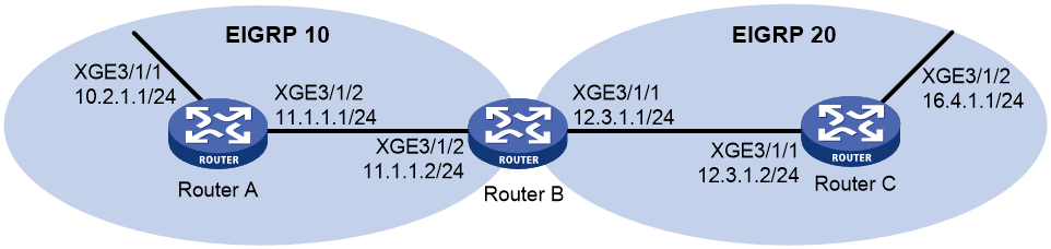
As shown in Figure 6, enable EIGRP on Router A, Router B, Router C, Router D, and Router E.
Router A has two paths (through Router B and Router C, respectively) to reach Router D. Each path has a bandwidth of 1000000 Kbps and a delay of 100 microseconds.
Configure EIGRP metrics for Ten-GigabitEthernet 3/1/2 on Router A to make the route learned from Router C the optimal route to the destination network 1.1.5.0/24.
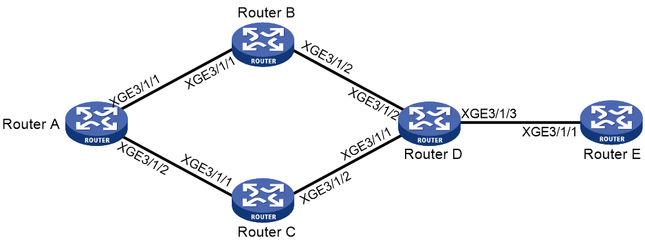
Table 1 Interface and IP address assignment
|
Device |
Interface |
IP address |
|
Router A |
XGE3/1/1 |
1.1.1.1/24 |
|
Router A |
XGE3/1/2 |
1.1.2.1/24 |
|
Router B |
XGE3/1/1 |
1.1.1.2/24 |
|
Router B |
XGE3/1/2 |
1.1.3.1/24 |
|
Router C |
XGE3/1/1 |
1.1.2.2/24 |
|
Router C |
XGE3/1/2 |
1.1.4.1/24 |
|
Router D |
XGE3/1/1 |
1.1.4.2/24 |
|
Router D |
XGE3/1/2 |
1.1.3.2/24 |
|
Router D |
XGE3/1/3 |
1.1.5.1/24 |
|
Router E |
XGE3/1/1 |
1.1.5.2/32 |
Procedure
1. Configure IP addresses for interfaces. (Details not shown.)
2. Configure basic EIGRP settings:
# Configure Router A.
<RouterA> system-view
[RouterA] eigrp 1
[RouterA-eigrp-1] address-family ipv4
[RouterA-eigrp-1-ipv4] network 1.1.0.0 0.0.255.255
[RouterA-eigrp-1-ipv4] quit
# Configure Router B.
<RouterB> system-view
[RouterB] eigrp 1
[RouterB-eigrp-1] address-family ipv4
[RouterB-eigrp-1-ipv4] network 1.1.0.0 0.0.255.255
[RouterB-eigrp-1-ipv4] quit
# Configure Router C.
<RouterC> system-view
[RouterC] eigrp 1
[RouterC-eigrp-1] address-family ipv4
[RouterC-eigrp-1-ipv4] network 1.1.0.0 0.0.255.255
[RouterC-eigrp-1-ipv4] quit
# Configure Router D.
<RouterD> system-view
[RouterD] eigrp 1
[RouterD-eigrp-1] address-family ipv4
[RouterD-eigrp-1-ipv4] network 1.1.0.0 0.0.255.255
[RouterD-eigrp-1-ipv4] quit
# Configure Router E.
<RouterE> system-view
[RouterE] eigrp 1
[RouterE-eigrp-1] address-family ipv4
[RouterE-eigrp-1-ipv4] network 1.1.0.0 0.0.255.255
[RouterE-eigrp-1-ipv4] quit
# Display topology table information for EIGRP process 1 on Router A.
[RouterA] display eigrp 1 topology
EIGRP topology for AS 1 with Router ID 1.1.1.1
Destination FD State Successor Out interface
1.1.1.0/24 5120 Passive Directed XGE3/1/1
1.1.2.0/24 5120 Passive Directed XGE3/1/2
1.1.3.0/24 7680 Passive 1.1.1.2 XGE3/1/1
1.1.4.0/24 7680 Passive 1.1.2.2 XGE3/1/2
1.1.5.0/24 10240 Passive 1.1.2.2 XGE3/1/2
1.1.1.2 XGE3/1/1
The output shows that Router A has two EIGRP routes to the network 1.1.5.0/24 with next hops of Router B (1.1.1.2) and Router C (1.1.2.2), respectively. The FD for the route is 10240.
3. Configure metrics for an EIGRP interface:
# Configure a delay of 50 microseconds for Ten-GigabitEthernet 3/1/2 on Router A.
[RouterA] interface ten-gigabitethernet 3/1/2
[RouterA-Ten-GigabitEthernet3/1/2] eigrp 1 metric delay 5
Verifying the configuration
# Display topology table information for EIGRP process 1 on Ten-GigabitEthernet 3/1/2 of Router A.
[RouterA] display eigrp 1 topology
EIGRP topology for AS 1 with Router ID 1.1.1.1
Destination FD State Successor Out interface
1.1.1.0/24 5120 Passive Directed XGE3/1/1
1.1.2.0/24 3840 Passive Directed XGE3/1/2
1.1.3.0/24 7680 Passive 1.1.1.2 XGE3/1/1
1.1.4.0/24 6400 Passive 1.1.2.2 XGE3/1/2
1.1.5.0/24 8960 Passive 1.1.2.2 XGE3/1/2
The output shows that Router A chooses Router C as the successor after interface metric configuration.
Example: Configuring EIGRP route redistribution
Network configuration
As shown in Figure 7, Router B runs two EIGRP processes, EIGRP 10 and EIGRP 20. Router B uses EIGRP 10 to exchange routing information with Router A, and uses EIGRP 20 to exchange routing information with Router C.
Configure Router B to redistribute direct routes and routes of EIGRP 10 to EIGRP 20. This ensures that Router C can learn routes to networks 10.2.1.0/24 and 11.1.1.0/24, but Router A cannot learn routes to networks 12.3.1.0/24 and 16.4.1.0/24.
Procedure
1. Configure IP addresses for interfaces. (Details not shown.)
2. Configure route redistribution:
# Configure Router B to redistribute direct routes and routes of EIGRP 10 to EIGRP 20.
<RouterB> system-view
[RouterB] eigrp 20
[RouterB-eigrp-20] address-family ipv4
[RouterB-EIGRP-20-ipv4] import-route direct
[RouterB-EIGRP-20-ipv4] import-route eigrp 10
[RouterB-EIGRP-20-ipv4] quit
Verifying the configuration
# Display topology table information for Router C.
[RouterC] display eigrp topology
EIGRP topology for AS 20 with Router ID 12.3.1.2
Destination FD State Successor Out interface
10.2.1.0/24 284160 Passive 12.3.1.1 XGE3/1/1
11.1.1.0/24 284160 Passive 12.3.1.1 XGE3/1/1
12.3.1.0/24 5120 Passive Directed XGE3/1/1
16.4.1.0/24 5120 Passive Directed XGE3/1/2
The output shows that Router C has learned from Router B the direct route 11.1.1.0/24 and the route 10.2.1.0/24 of EIGRP 10.
Example: Configuring EIGRP route summarization
Network configuration
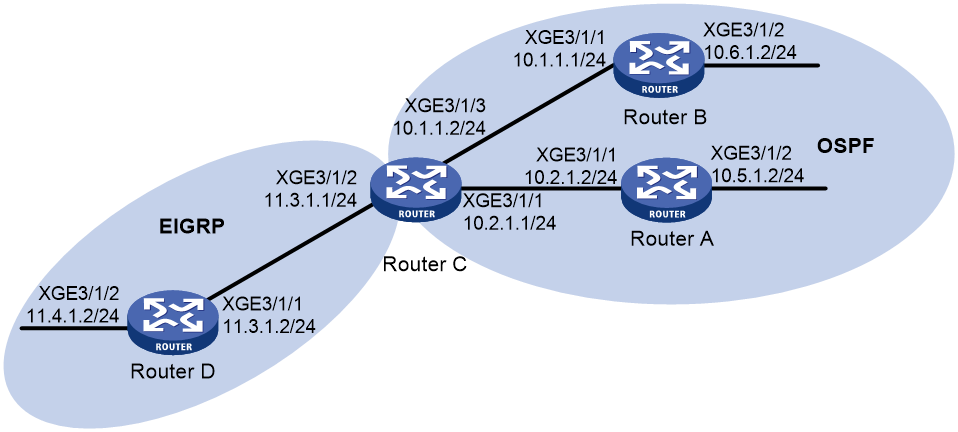
As shown in Figure 8, Router A and Router B run OSPF. Router D runs EIGRP. Router C runs OSPF and EIGRP at the same time.
Configure Router C to redistribute OSPF routes, so that Router D can learn routes to networks 10.1.1.0/24, 10.2.1.0/24, 10.5.1.0/24, and 10.6.1.0/24.
To reduce the routing table size of Router D, configure route summarization on Router C to advertise summary route 10.0.0.0/8 instead of the more specific routes.
Procedure
1. Configure IP addresses for interfaces. (Details not shown.)
2. Configure basic OSPF settings:
# Configure Router A.
<RouterA> system-view
[RouterA] ospf
[RouterA-ospf-1] area 0
[RouterA-ospf-1-area-0.0.0.0] network 10.5.1.0 0.0.0.255
[RouterA-ospf-1-area-0.0.0.0] network 10.2.1.0 0.0.0.255
[RouterA-ospf-1-area-0.0.0.0] quit
# Configure Router B.
<RouterB> system-view
[RouterB] ospf
[RouterB-ospf-1] area 0
[RouterB-ospf-1-area-0.0.0.0] network 10.1.1.0 0.0.0.255
[RouterB-ospf-1-area-0.0.0.0] network 10.6.1.0 0.0.0.255
[RouterB-ospf-1-area-0.0.0.0] quit
# Configure Router C.
<RouterC> system-view
[RouterC] ospf
[RouterC-ospf-1] area 0
[RouterC-ospf-1-area-0.0.0.0] network 10.1.1.0 0.0.0.255
[RouterC-ospf-1-area-0.0.0.0] network 10.2.1.0 0.0.0.255
[RouterC-ospf-1-area-0.0.0.0] quit
[RouterC-ospf-1] quit
3. Configure basic EIGRP settings:
# Configure Router C.
[RouterC] eigrp 1
[RouterC-eigrp-1] address-family ipv4
[RouterC-eigrp-1-ipv4] network 11.3.1.0 0.0.0.255
[RouterC-eigrp-1-ipv4] quit
# Configure Router D.
<RouterD> system-view
[RouterD] eigrp 1
[RouterD-eigrp-1] address-family ipv4
[RouterD-eigrp-1-ipv4] network 11.3.1.0 0.0.0.255
[RouterD-eigrp-1-ipv4] network 11.4.1.0 0.0.0.255
[RouterD-eigrp-1-ipv4] quit
# Configure Router C to redistribute routes from OSPF process 1 and direct routes.
[RouterC] eigrp 1
[RouterC-eigrp-1] address-family ipv4
[RouterC-eigrp-1-ipv4] import-route ospf 1
[RouterC-eigrp-1-ipv4] import-route direct
[RouterC-eigrp-1-ipv4] quit
# Display topology table information for Router D.
[RouterD] display eigrp topology
EIGRP topology for AS 1 with Router ID 11.1.1.1
Destination FD State Successor Out interface
10.1.1.0/24 284160 Passive 11.3.1.1 XGE3/1/1
10.2.1.0/24 284160 Passive 11.3.1.1 XGE3/1/1
10.5.1.2/32 284160 Passive 11.3.1.1 XGE3/1/1
10.6.1.2/32 284160 Passive 11.3.1.1 XGE3/1/1
11.3.1.0/24 5120 Passive Directed XGE3/1/1
11.4.1.0/24 5120 Passive Directed XGE3/1/2
4. Configure route summarization:
# Enable automatic route summarization on Router C.
[RouterC] eigrp 1
[RouterC-eigrp-1] address-family ipv4
[RouterC-eigrp-1-ipv4] summary automatic
[RouterC-eigrp-1-ipv4] quit
Verifying the configuration
# Display topology table information for Router D.
[RouterD] display eigrp topology
EIGRP topology for AS 1 with Router ID 11.1.1.1
Destination FD State Successor Out interface
10.0.0.0/8 284160 Passive 11.3.1.1 XGE3/1/1
11.0.0.0/8 7680 Passive 11.3.1.1 XGE3/1/1
11.3.1.0/24 5120 Passive Directed XGE3/1/1
11.4.1.0/24 5120 Passive Directed XGE3/1/2
The output shows that Router C advertises only a summary route 10.0.0.0/8 to Router D.
Troubleshooting EIGRP
EIGRP neighbor relationship cannot be established
Symptom
A router cannot establish EIGRP neighbor relationship with the adjacent router.
Solution
To resolve the problem:
1. Use the display eigrp command to display EIGRP configuration information and verify that the AS numbers and metric weights are identical on both routers.
2. Use the display eigrp interface command to display EIGRP interface information and verify that the interface running the EIGRP process is in up state.
3. Use the display eigrp peer command to display EIGRP neighbor information and verify that the neighbor state is up.
4. Verify that physical connection and lower-layer protocol are operating correctly. For example, if the peer router cannot be pinged, a problem exists on physical connection and lower-layer protocol.
5. Verify that the EIGRP timers are correctly configured. The hold timer must be at least three times the hello timer on an interface.
