- Table of Contents
-
- 07-Layer 3—IP Routing Configuration Guide
- 00-Preface
- 01-Basic IP routing configuration
- 02-Static routing configuration
- 03-RIP configuration
- 04-OSPF configuration
- 05-IS-IS configuration
- 06-EIGRP configuration
- 07-BGP configuration
- 08-Policy-based routing configuration
- 09-IPv6 static routing configuration
- 10-RIPng configuration
- 11-OSPFv3 configuration
- 12-IPv6 policy-based routing configuration
- 13-Routing policy configuration
- 14-DCN configuration
- Related Documents
-
| Title | Size | Download |
|---|---|---|
| 11-OSPFv3 configuration | 842.67 KB |
Contents
Comparison of OSPFv3 with OSPFv2
Enabling a lightweight OSPFv3 process
Configuring OSPFv3 area parameters
Configuring an OSPFv3 virtual link
Configuring OSPFv3 network types
Restrictions and guidelines for OSPFv3 network type configuration
Setting the broadcast network type for an OSPFv3 interface
Setting the NBMA network type for an OSPFv3 interface
Setting the P2MP network type for an OSPFv3 interface
Setting the P2P network type for an OSPFv3 interface
Configuring OSPFv3 route control
Configuring OSPFv3 inter-area route summarization
Configuring redistributed route summarization
Configuring OSPFv3 received route filtering
Configuring Inter-Area-Prefix LSA filtering
Setting an OSPFv3 cost for an interface
Changing the link cost of a Layer 3 aggregate interface when its bandwidth falls below the threshold
Enabling OSPFv3 to adjust the interface cost according to the link quality
Enabling OSPFv3 to advertise the maximum link cost to neighbors
Setting the maximum number of OSPFv3 ECMP routes
Setting a preference for OSPFv3
Configuring OSPFv3 route redistribution
Configuring default route redistribution
Advertising OSPFv3 link state information to BGP
Configuring the OSPFv3 link tag feature
Configuring OSPFv3 to advertise network performance parameters
About OSPFv3 network performance parameters
Advertising link delay information
Advertising link bandwidth information
Configuring OSPFv3 flexible algorithm
About OSPFv3 flexible algorithm
OSPFv3 flexible algorithm tasks at a glance
Mapping an affinity attribute name to an affinity bit
Assigning affinity attributes to OSPFv3 links
Configuring a flexible algorithm
Configuring the metric type of a flexible algorithm
Configuring flexible algorithm FRR
Configuring flexible algorithm TI-LFA FRR
Set the priority of an FRR backup path selection policy for flexible algorithm
Applying a flexible algorithm to SRv6
Setting LSA transmission delay
Setting SPF calculation interval
Setting the LSA arrival interval
Setting the LSA generation interval
Setting a DR priority for an interface
Configuring OSPFv3 packet parameters
Ignoring MTU check for DD packets
Setting the DSCP value for outgoing OSPFv3 packets
Disabling interfaces from receiving and sending OSPFv3 packets
Accelerating OSPFv3 convergence speed
Configuring prefix suppression
Configuring OSPFv3 advanced features
Configuring the virtual system feature
Enabling OSPFv3 to adjust the interface cost according to the BFD session state
Suppressing interface cost adjustment according to the BFD session state upon BFD session flapping
Configuring OSPFv3 FRR to use the LFA algorithm to calculate a backup next hop
Configuring OSPFv3 FRR to use a backup next hop in a routing policy
Setting the priority for FRR backup path selection policies
Configuring BFD control packet mode for OSPFv3 FRR
Configuring BFD echo packet mode for OSPFv3 FRR
Configuring OSPFv3 authentication
Applying an IPsec profile for authenticating OSPFv3 packets
Configuring OSPFv3 logging and SNMP notifications
Enabling logging for neighbor state changes
Setting the maximum number of OSPFv3 logs
Configuring OSPFv3 network management
Display and maintenance commands for OSPFv3
Example: Configuring OSPFv3 stub area
Example: Configuring OSPFv3 NSSA area
Example: Configuring OSPFv3 DR election
Example: Configuring OSPFv3 route redistribution
Example: Configuring OSPFv3 route summarization
Example: Configuring OSPFv3 GR
Example: Configuring BFD for OSPFv3
Example: Configuring OSPFv3 FRR
Example: Configuring OSPFv3 IPsec profile
Configuring OSPFv3
About OSPFv3
This chapter describes how to configure RFC 2740-compliant Open Shortest Path First version 3 (OSPFv3) for an IPv6 network.
Comparison of OSPFv3 with OSPFv2
OSPFv3 and OSPFv2 have the following in common:
· 32-bit router ID and area ID.
· Hello, Database Description (DD), Link State Request (LSR), Link State Update (LSU), Link State Acknowledgment (LSAck).
· Mechanisms for finding neighbors and establishing adjacencies.
· Mechanisms for advertising and aging LSAs.
OSPFv3 and OSPFv2 have the following differences:
· OSPFv3 runs on a per-link basis. OSPFv2 runs on a per-IP-subnet basis.
· OSPFv3 supports running multiple processes on an interface, but OSPFv2 does not support.
· OSPFv3 identifies neighbors by router ID. OSPFv2 identifies neighbors by IP address.
For more information about OSPFv2, see "Configuring OSPF."
OSPFv3 packets
OSPFv3 uses the following packet types:
· Hello—Periodically sent to find and maintain neighbors, containing timer values, information about the DR, BDR, and known neighbors.
· DD—Describes the digest of each LSA in the LSDB, exchanged between two routers for data synchronization.
· LSR—Requests needed LSAs from the neighbor. After exchanging the DD packets, the two routers know which LSAs of the neighbor are missing from their LSDBs. They then send an LSR packet to each other, requesting the missing LSAs. The LSA packet contains the digest of the missing LSAs.
· LSU—Transmits the requested LSAs to the neighbor.
· LSAck—Acknowledges received LSU packets.
OSPFv3 LSA types
OSPFv3 sends routing information in LSAs. The following LSAs are commonly used:
· Router LSA—Type-1 LSA, originated by all routers. This LSA describes the collected states of the router's interfaces to an area, and is flooded throughout a single area only.
· Network LSA—Type-2 LSA, originated for broadcast and NBMA networks by the DR. This LSA contains the list of routers connected to the network, and is flooded throughout a single area only.
· Inter-Area-Prefix LSA—Type-3 LSA, originated by ABRs and flooded throughout the LSA's associated area. Each Inter-Area-Prefix LSA describes a route with IPv6 address prefix to a destination outside the area, yet still inside the AS.
· Inter-Area-Router LSA—Type-4 LSA, originated by ABRs and flooded throughout the LSA's associated area. Each Inter-Area-Router LSA describes a route to ASBR.
· AS External LSA—Type-5 LSA, originated by ASBRs, and flooded throughout the AS, except stub areas and Not-So-Stubby Areas (NSSAs). Each AS External LSA describes a route to another AS. A default route can be described by an AS External LSA.
· NSSA LSA—Type-7 LSA, originated by ASBRs in NSSAs and flooded throughout a single NSSA. NSSA LSAs describe routes to other ASs.
· Link LSA—Type-8 LSA. A router originates a separate Link LSA for each attached link. Link LSAs have link-local flooding scope. Each Link LSA describes the IPv6 address prefix of the link and Link-local address of the router.
· Intra-Area-Prefix LSA—Type-9 LSA. Each Intra-Area-Prefix LSA contains IPv6 prefix information on a router, stub area, or transit area information, and has area flooding scope. It was introduced because Router LSAs and Network LSAs contain no address information.
· Intra-Area-TE LSA—Type-10 LSA, generated by a router configured with an IPv6 router ID or a router in an OSPFv3 area enabled with MPLS TE. Intra-Area-TE LSAs generated by a router configured with an IPv6 router ID contain basic link state information, IPv6 Router ID, neighbor ID, local interface's IPv6 address, and remote interface's IPv6 address. Intra-Area-TE LSAs generated by a router in an OSPFv3 area enabled with MPLS TE contain TE attribute information.
· Grace LSA—Type-11 LSA, generated by a GR restarter at reboot and transmitted on the local link. The GR restarter describes the cause and interval of the reboot in the Grace LSA to notify its neighbors that it performs a GR operation.
Protocols and standards
· RFC 2328, OSPF Version 2
· RFC 3101, OSPF Not-So-Stubby Area (NSSA) Option
· RFC 4552, Authentication/Confidentiality for OSPFv3
· RFC 5187, OSPFv3 Graceful Restart
· RFC 5286, Basic Specification for IP Fast Reroute: Loop-Free Alternates
· RFC 5329, Traffic Engineering Extensions to OSPF Version 3
· RFC 5340, OSPF for IPv6
· RFC 5523, OSPFv3-Based Layer 1 VPN Auto-Discovery
· RFC 5643, Management Information Base for OSPFv3
· RFC 6506, Supporting Authentication Trailer for OSPFv3
· RFC 6565, OSPFv3 as a Provider Edge to Customer Edge (PE-CE) Routing Protocol
· RFC 6969, OSPFv3 Instance ID Registry Update
· RFC 7166, Supporting Authentication Trailer for OSPFv3
OSPFv3 tasks at a glance
To configure OSPFv3, perform the following tasks:
2. (Optional.) Enabling a lightweight OSPFv3 process
3. (Optional.) Configuring OSPFv3 area parameters
¡ Configuring an OSPFv3 virtual link
Perform this task on an ABR to create a virtual link when connectivity cannot be maintained between a non-backbone area and the backbone, or within the backbone.
5. (Optional.) Configuring OSPFv3 network types
¡ Setting the broadcast network type for an OSPFv3 interface
¡ Setting the NBMA network type for an OSPFv3 interface
¡ Setting the P2MP network type for an OSPFv3 interface
¡ Setting the P2P network type for an OSPFv3 interface
6. (Optional.) Configuring OSPFv3 route control
¡ Configuring OSPFv3 inter-area route summarization
¡ Configuring OSPFv3 received route filtering
¡ Configuring Inter-Area-Prefix LSA filtering
¡ Setting an OSPFv3 cost for an interface
¡ Changing the link cost of a Layer 3 aggregate interface when its bandwidth falls below the threshold
¡ Enabling OSPFv3 to adjust the interface cost according to the link quality
¡ Enabling OSPFv3 to advertise the maximum link cost to neighbors
¡ Setting the maximum number of OSPFv3 ECMP routes
¡ Setting a preference for OSPFv3
¡ Configuring OSPFv3 route redistribution
¡ Advertising OSPFv3 link state information to BGP
¡ Configuring the OSPFv3 link tag feature
7. (Optional.) Configuring OSPFv3 to advertise network performance parameters
¡ Advertising link delay information
¡ Advertising link bandwidth information
8. (Optional.) Configuring OSPFv3 flexible algorithm
9. (Optional.) Setting OSPFv3 timers
¡ Setting OSPFv3 packet timers
¡ Setting LSA transmission delay
¡ Setting SPF calculation interval
¡ Setting the LSA generation interval
¡ Setting the LSU transmit rate
10. (Optional.) Setting a DR priority for an interface
11. (Optional.) Configuring OSPFv3 packet parameters
¡ Ignoring MTU check for DD packets
¡ Setting the DSCP value for outgoing OSPFv3 packets
¡ Disabling interfaces from receiving and sending OSPFv3 packets
12. (Optional.) Accelerating OSPFv3 convergence speed
¡ Configuring prefix suppression
13. (Optional.) Configuring OSPFv3 advanced features
¡ Configuring OSPFv3 isolation
¡ Configuring the virtual system feature
14. (Optional.) Enhancing OSPFv3 availability
15. (Optional.) Enhancing OSPFv3 security
¡ Configuring OSPFv3 authentication
¡ Applying an IPsec profile for authenticating OSPFv3 packets
16. (Optional.) Configuring OSPFv3 logging and SNMP notifications
¡ Enabling logging for neighbor state changes
¡ Setting the maximum number of OSPFv3 logs
¡ Configuring OSPFv3 network management
Enabling OSPFv3
About this task
To enable an OSPFv3 process on a router:
1. Enable the OSPFv3 process globally.
2. Assign the OSPFv3 process a router ID.
3. Enable the OSPFv3 process on related interfaces.
An OSPFv3 process ID has only local significance. Process 1 on a router can exchange packets with process 2 on another router.
OSPFv3 requires you to manually specify a router ID for each router in an AS. Make sure all assigned router IDs in the AS are unique.
Restrictions and guideline
If a router runs multiple OSPFv3 processes, you must specify a unique router ID for each process.
Procedure
1. Enter system view.
system-view
2. Enable an OSPFv3 process and enter its view.
ospfv3 [ process-id | vpn-instance vpn-instance-name ] *
By default, no OSPFv3 processes are enabled.
3. Specify a router ID.
router-id router-id
By default, no router ID is configured.
4. Enter interface view.
interface interface-type interface-number
5. Enable an OSPFv3 process on the interface.
ospfv3 process-id area area-id [ instance instance-id ]
By default, no OSPFv3 processes are enabled on an interface.
Enabling a lightweight OSPFv3 process
About this task
Enabling multiple OSPFv3 processes on a device might cause memory insufficiency. To resolve this issue, perform this task to enable lightweight OSPFv3 processes.
Restrictions and guidelines
Although lightweight processes use less memory resources than traditional processes, device performance might degrade when a large number of neighbors and routes exist. As a best practice, plan the number of lightweight OSPFv3 processes to be enabled on the basis of the device resource condition.
Procedure
1. Enter non-default vSystem view.
system-view
2. Enable a lightweight OSPFv3 process and enter its view.
ospfv3 [ process-id ] [ lite | vpn-instance vpn-instance-name ] *
By default, no OSPFv3 processes are enabled.
Configuring OSPFv3 area parameters
About OSPFv3 areas
OSPFv3 has the same stub area, NSSA area, and virtual link features as OSPFv2.
After you split an OSPFv3 AS into multiple areas, the LSA number is reduced and OSPFv3 applications are extended. To further reduce the size of routing tables and the number of LSAs, configure the non-backbone areas at an AS edge as stub areas.
A stub area cannot import external routes, but an NSSA area can import external routes into the OSPFv3 routing domain while retaining other stub area characteristics.
Non-backbone areas exchange routing information through the backbone area, so the backbone and non-backbone areas (including the backbone itself) must be fully meshed. If no connectivity can be achieved, configure virtual links.
Configuring a stub area
Restrictions and guidelines
To configure a stub area, you must perform this task on all routers attached to the area.
Procedure
1. Enter system view.
system-view
2. Enter OSPFv3 view.
ospfv3 [ process-id | vpn-instance vpn-instance-name ] *
3. Enter OSPFv3 area view.
area area-id
4. Configure the area as a stub area.
stub [ default-route-advertise-always | no-summary ] *
By default, no area is configured as a stub area.
The no-summary keyword is only available on the ABR of a stub area. If you specify the no-summary keyword, the ABR only advertises a default route in an Inter-Area-Prefix LSA into the stub area.
5. (Optional.) Set a cost for the default route advertised to the stub area.
default-cost cost-value
By default, the cost for the default route advertised to the stub area is 1.
Configuring an NSSA area
Restrictions and guidelines
To configure an NSSA area, you must perform this task on all routers attached to the area.
Procedure
1. Enter system view.
system-view
2. Enter OSPFv3 view.
ospfv3 [ process-id | vpn-instance vpn-instance-name ] *
3. Enter OSPFv3 area view.
area area-id
4. Configure the area as an NSSA area.
nssa [ default-route-advertise [ cost cost-value | nssa-only | route-policy route-policy-name | tag tag | type type ] * | no-import-route | no-summary | [ translate-always | translate-never ] | suppress-fa | translator-stability-interval value ] *
By default, no area is configured as an NSSA area.
To configure a totally NSSA area, execute the nssa no-summary command on the ABR. The ABR of a totally NSSA area does not advertise inter-area routes into the area.
5. (Optional.) Set a cost for the default route advertised to the NSSA area.
default-cost cost-value
By default, the cost for the default route advertised to the NSSA area is 1.
This command takes effect only on the ABR/ASBR of an NSSA or totally NSSA area.
Configuring an OSPFv3 virtual link
About this task
You can configure a virtual link to maintain connectivity between a non-backbone area and the backbone, or in the backbone itself.
Restrictions and guidelines
Both ends of a virtual link are ABRs that must be configured with the vlink-peer command.
Procedure
1. Enter system view.
system-view
2. Enter OSPFv3 view.
ospfv3 [ process-id | vpn-instance vpn-instance-name ] *
3. Enter OSPFv3 area view.
area area-id
4. Configure a virtual link.
vlink-peer router-id [ dead seconds | hello seconds | instance instance-id | ipsec-profile profile-name | [ { hmac-sha-256 | hmac-sm3 } key-id { cipher | plain } string | keychain keychain-name ] | retransmit seconds | trans-delay seconds ] *
Configuring OSPFv3 network types
Restrictions and guidelines for OSPFv3 network type configuration
Based on the link layer protocol, OSPFv3 classifies networks into different types, including broadcast, NBMA, P2MP, and P2P.
· An NBMA network must be fully connected. Any two routers in the network must be directly reachable to each other through a virtual circuit. If no such direct link is available, you must change the network type through a command.
· If direct connections are not available between some routers on an NBMA network, the type of interfaces associated must be configured as P2MP, or as P2P for interfaces with only one neighbor.
Setting the broadcast network type for an OSPFv3 interface
1. Enter system view.
system-view
2. Enter interface view.
interface interface-type interface-number
3. Set the network type to broadcast for the OSPFv3 interface.
ospfv3 network-type broadcast [ instance instance-id ]
By default, the network type of an interface depends on the media type of the interface.
When the link layer protocol is Ethernet or FDDI, the network type is broadcast by default.
Setting the NBMA network type for an OSPFv3 interface
Restrictions and guidelines
For NBMA interfaces, you must specify the link-local IP addresses and DR priorities for their neighbors because these interfaces cannot find neighbors by broadcasting hello packets.
Procedure
1. Enter system view.
system-view
2. Enter interface view.
interface interface-type interface-number
3. Set the network type to NBMA for the OSPFv3 interface.
ospfv3 network-type nbma [ instance instance-id ]
When the link layer protocol is ATM or X.25, the network type is NBMA by default.
4. (Optional.) Set the router priority for the interface
ospfv3 dr-priority priority
By default, an interface has a router priority of 1.
An interface's router priority determines its privilege in DR/BDR selection.
5. Specify an NBMA neighbor.
ospfv3 peer ipv6-address [ cost cost-value | dr-priority priority ] [ instance instance-id ]
By default, no link-local address is specified for the neighbor interface.
Setting the P2MP network type for an OSPFv3 interface
Restrictions and guidelines
For P2MP interfaces (only when in unicast mode), you must specify the link-local IP addresses of their neighbors because these interfaces cannot find neighbors by broadcasting hello packets.
Procedure
1. Enter system view.
system-view
2. Enter interface view.
interface interface-type interface-number
3. Set the network type to P2MP for the OSPFv3 interface.
ospfv3 network-type p2mp [ unicast ] [ instance instance-id ]
By default, the network type of an interface depends on the media type of the interface.
4. Specify a P2MP unicast neighbor.
ospfv3 peer ipv6-address [ cost cost-value | dr-priority priority ] [ instance instance-id ]
By default, no link-local address is specified for the neighbor interface.
Setting the P2P network type for an OSPFv3 interface
1. Enter system view.
system-view
2. Enter interface view.
interface interface-type interface-number
3. Set the network type to P2P for the OSPFv3 interface.
ospfv3 network-type p2p [ instance instance-id ]
When the link layer protocol is PPP, LAPB, HDLC, or POS, the network type is P2P by default.
Configuring OSPFv3 route control
Configuring OSPFv3 inter-area route summarization
About this task
If contiguous network segments exist in an area, you can summarize them into one network segment on the ABR. The ABR will advertise only the summary route. Any LSA on the specified network segment will not be advertised, reducing the LSDB size in other areas.
Procedure
1. Enter system view.
system-view
2. Enter OSPFv3 view.
ospfv3 [ process-id | vpn-instance vpn-instance-name ] *
3. Enter OSPFv3 area view.
area area-id
4. Configure route summarization on the ABR.
abr-summary ipv6-address prefix-length [ not-advertise ] [ cost cost-value ]
By default, route summarization is not configured on an ABR.
Configuring redistributed route summarization
About this task
Perform this task to enable an ASBR to summarize external routes within the specified address range into a single route.
An ASBR can summarize routes in the following LSAs:
· Type-5 LSAs.
· Type-7 LSAs in an NSSA area.
· Type-5 LSAs translated from Type-7 LSAs in an NSSA area if the ASBR (also an ABR) is a translator. If the ASBR is not a translator, it cannot summarize routes in Type-5 LSAs translated from Type-7 LSAs.
Procedure
1. Enter system view.
system-view
2. Enter OSPFv3 view.
ospfv3 [ process-id | vpn-instance vpn-instance-name ] *
3. Configure route summarization on an ASBR.
asbr-summary ipv6-address prefix-length [ cost cost-value | not-advertise | nssa-only | tag tag ] *
By default, route summarization is not configured on an ASBR.
Configuring OSPFv3 received route filtering
About this task
This task allows you to filter routes calculated by using received LSAs.
Procedure
1. Enter system view.
system-view
2. Enter OSPFv3 view.
ospfv3 [ process-id | vpn-instance vpn-instance-name ] *
3. Configure OSPFv3 to filter routes calculated by using received LSAs.
filter-policy { ipv6-acl-number [ gateway prefix-list-name ] | prefix-list prefix-list-name [ gateway prefix-list-name ] | gateway prefix-list-name | route-policy route-policy-name } import
By default, OSPFv3 accepts all routes calculated by using received LSAs.
This command can only filter routes computed by OSPFv3. Only routes not filtered out can be added into the local routing table.
Configuring Inter-Area-Prefix LSA filtering
Restrictions and guidelines
The filter command takes effect only on ABRs.
Procedure
1. Enter system view.
system-view
2. Enter OSPFv3 view.
ospfv3 [ process-id | vpn-instance vpn-instance-name ] *
3. Enter OSPFv3 area view.
area area-id
4. Configure OSPFv3 to filter Inter-Area-Prefix LSAs.
filter { ipv6-acl-number | prefix-list prefix-list-name | route-policy route-policy-name } { export | import }
By default, OSPFv3 accepts all Inter-Area-Prefix LSAs.
Setting an OSPFv3 cost for an interface
About this task
You can set an OSPFv3 cost for an interface with one of the following methods:
· Set the cost value in interface view.
· Set a bandwidth reference value for the interface, and OSPFv3 computes the cost automatically based on the bandwidth reference value by using the following formula:
Interface OSPFv3 cost = Bandwidth reference value (100 Mbps) / Interface bandwidth (Mbps)
¡ If the calculated cost is greater than 65535, the value of 65535 is used.
¡ If the calculated cost is smaller than 1, the value of 1 is used.
· If no cost is set for an interface, OSPFv3 automatically computes the cost for the interface.
Setting a cost in interface view
1. Enter system view.
system-view
2. Enter interface view.
interface interface-type interface-number
3. Set an OSPFv3 cost for the interface.
ospfv3 cost cost-value [ instance instance-id ]
By default, the OSPFv3 cost is 1 for a VLAN interface, is 0 for a loopback interface. The OSPFv3 cost is automatically computed according to the interface bandwidth for other interfaces.
Setting a bandwidth reference value
1. Enter system view.
system-view
2. Enter OSPFv3 view.
ospfv3 [ process-id | vpn-instance vpn-instance-name ] *
3. Set a bandwidth reference value.
bandwidth-reference value
The default bandwidth reference value is 100 Mbps.
Changing the link cost of a Layer 3 aggregate interface when its bandwidth falls below the threshold
About this task
When a member port of a Layer 3 aggregate interface goes down, the bandwidth of the aggregate interface decreases and services might be interrupted. To resolve this issue, perform this task to change the link cost of a Layer 3 aggregate interface as follows:
· When the bandwidth of the Layer 3 aggregate interface falls below the specified threshold, the aggregate interface uses the specified link cost. Make sure the link cost you specified is larger than the original link cost, so that OSPFv3 can select an optimal path for traffic forwarding.
· When the bandwidth of the Layer 3 aggregate interface is equal to or larger than the bandwidth threshold, the aggregate interface uses the original link cost.
For more information about OSPFv3 link cost, see "Setting an OSPFv3 cost for an interface."
Restrictions and guidelines
This feature applies to only Layer 3 aggregate interfaces and Layer 3 aggregate subinterfaces.
Procedure
1. Enter system view.
system-view
2. Enter interface view.
interface interface-type interface-number
3. Change the link cost of the interface to the specified value when the bandwidth of the interface falls below the specified threshold.
ospfv3 cost-fallback cost-value threshold bandwidth-value [ instance instance-id ]
By default, an aggregate interface uses the original link cost.
Enabling OSPFv3 to adjust the interface cost according to the link quality
About this task
Error codes, which refer to bit differences between the received and source signals, cannot be avoided because of inevitable link aging and optical path jitter problems. A high error code ratio might cause service degradation or interruption.
To reduce the impact of error codes on an OSPFv3 network, you can enable OSPFv3 to adjust the interface cost according to the link quality.
After you configure this feature on an interface, OSPFv3 adjusts the interface cost as follows:
· When the link quality of the interface becomes LOW, OSPFv3 increases the cost value for the interface.
· When the link quality of the interface restores to GOOD, OSPFv3 restores the cost value for the interface.
For more information about error code detection, see error code detection configuration in High Availability Configuration Guide.
Procedure
1. Enter system view.
system-view
2. Enter interface view.
interface interface-type interface-number
3. Enable OSPFv3 to adjust the link cost according to the link quality.
ospfv3 link-quality adjust-cost { max | cost-offset } [ instance instance-id ]
By default, OSPFv3 does not adjust the link cost according to the link quality.
Enabling OSPFv3 to advertise the maximum link cost to neighbors
About this task
On an OSPFv3 network, when a link recovers from failures or the state of an interface changes, OSPFv3 will re-establish neighbor relationships and perform route convergence. During the route convergence process, routing loops and traffic loss might occur because the convergence speeds of the nodes are different. To address this issue, enable OSPFv3 to advertise the maximum link cost to neighbors within the specified period of time, so the traffic forwarding path remains unchanged. After the specified period of time, OSPFv3 advertises the original link cost to neighbors and performs optimal route selection again.
Procedure
1. Enter system view.
system-view
2. Enter interface view.
interface interface-type interface-number
3. Enable OSPFv3 to advertise the maximum link cost to neighbors within the specified period of time.
ospfv3 peer hold-max-cost duration timer [ instance instance-id ]
By default, OSPFv3 advertises the original link cost to neighbors during a route convergence.
Setting the maximum number of OSPFv3 ECMP routes
About this task
OSPFv3 might find multiple equal-cost routes to the same destination, which can be used to share the traffic load. This task allows you to set the maximum number of ECMP routes.
Procedure
1. Enter system view.
system-view
2. Enter OSPFv3 view.
ospfv3 [ process-id | vpn-instance vpn-instance-name ] *
3. Set the maximum number of ECMP routes.
maximum load-balancing number
By default, the maximum number of ECMP routes is 64.
Setting a preference for OSPFv3
About this task
A router can run multiple routing protocols. The system assigns a priority for each protocol. When these routing protocols find the same route, the route found by the protocol with the highest priority is selected.
Procedure
1. Enter system view.
system-view
2. Enter OSPFv3 view.
ospfv3 [ process-id | vpn-instance vpn-instance-name ] *
3. Set a preference for OSPFv3.
preference [ ase ] { preference | route-policy route-policy-name } *
By default, the preference of OSPFv3 internal routes is 10, and the preference of OSPFv3 external routes is 150.
Configuring OSPFv3 route redistribution
Restrictions and guidelines
Because OSPFv3 is a link state routing protocol, it cannot directly filter LSAs to be advertised. OSPFv3 filters only redistributed routes. Only routes that are not filtered out can be advertised in LSAs.
Procedure
1. Enter system view.
system-view
2. Enter OSPFv3 view.
ospfv3 [ process-id | vpn-instance vpn-instance-name ] *
3. Configure OSPFv3 to redistribute routes from other routing protocols.
import-route bgp4+ [ as-number ] [ allow-ibgp ] [ cost cost-value | inherit-cost ] | nssa-only | route-policy route-policy-name | tag tag | type type ] *
import-route { direct | static | unr } [ cost cost-value | inherit-cost ] | nssa-only | route-policy route-policy-name | tag tag | type type ] *
import-route { isisv6 | ospfv3 | ripng } [ process-id | all-processes ] [ allow-direct | [ cost cost-value | inherit-cost ] | nssa-only | route-policy route-policy-name | tag tag | type type ] *
By default, route redistribution is disabled.
The import-route bgp4+ command redistributes only EBGP routes. The import-route bgp4+ allow-ibgp command redistributes both EBGP and IBGP routes, which might cause routing loops. There, use the import-route bgp4+ allow-ibgp command with caution.
4. (Optional.) Configure OSPFv3 to filter redistributed routes.
filter-policy { ipv6-acl-number | prefix-list prefix-list-name } export [ bgp4+ | direct | { isisv6 | ospfv3 | ripng } [ process-id ] | static | unr ]
By default, OSPFv3 accepts all redistributed routes.
This command filters only routes redistributed by the import-route command. If no routes are redistributed by the import-route command, this command does not take effect.
5. Set a tag for redistributed routes.
default tag tag
By default, the tag of redistributed routes is 1.
Configuring default route redistribution
About this task
The import-route command cannot redistribute a default external route. To redistribute a default route, perform this task.
Procedure
1. Enter system view.
system-view
2. Enter OSPFv3 view.
ospfv3 [ process-id | vpn-instance vpn-instance-name ] *
3. Redistribute a default route.
default-route-advertise [ [ always | permit-calculate-other ] | cost cost-value | route-policy route-policy-name | tag tag | type type ] *
By default, no default route is redistributed.
4. Set a tag for redistributed routes.
default tag tag
By default, the tag of redistributed routes is 1.
Advertising OSPFv3 link state information to BGP
About this task
After the device advertises OSPFv3 link state information to BGP, BGP can advertise the information for intended applications. For more information about BGP LS, see "Configuring BGP."
Advertising OSPFv3 link state information to BGP
1. Enter system view.
system-view
2. Enter OSPFv3 view.
ospfv3 [ process-id ]
3. Advertise OSPFv3 link state information to BGP.
distribute bgp-ls [ instance-id instance-id ]
By default, the device does not advertise OSPFv3 link state information to BGP.
Advertising OSPFv3 link state information containing MPLS TE attributes to BGP
1. Enter system view.
system-view
2. Enter OSPFv3 view.
ospfv3 [ process-id ]
3. Advertise OSPFv3 link state information to BGP.
distribute bgp-ls [ instance-id instance-id ]
By default, the device does not advertise OSPFv3 link state information to BGP.
4. Configure an IPv6 Router ID for the device.
te-router-id ipv6-address
By default, no IPv6 Router ID is configured for a device.
After you execute this command, OSPFv3 generates Intra-Area-TE LSAs containing basic link state information, IPv6 Router ID, neighbor ID, local interface's IPv6 address, and remote interface's IPv6 address.
5. Enable OSPFv3 to generate Intra-Area-TE LSAs containing TE attribute information.
a. Return to system view.
quit
b. Enable MPLS TE and enter MPLS TE view.
mpls te
By default, MPLS TE is disabled.
For more information about MPLS TE, see MPLS TE configuration in MPLS Configuration Guide.
c. Enter OSPFv3 view.
ospfv3 [ process-id | vpn-instance vpn-instance-name ] *
d. Enter OSPFv3 area view.
area area-id
e. Enable MPLS TE for the OSPFv3 area.
mpls te enable
By default, MPLS TE is disabled for an OSPFv3 area.
After you execute this command, OSPFv3 generates Intra-Area-TE LSAs containing basic link state information and TE attribute information.
Configuring the OSPFv3 link tag feature
About this task
The interface link tag feature can work together with the link tag inheritance feature to filter routes. For example, you can set an OSPFv3 link tag for Device A and enable OSPFv3 link tag inheritance on Device B to filter routes as follows:
1. Device A advertises the OSPFv3 link tag in E-router LSAs.
2. After receiving the LSAs advertised by Device A, Device B inherits the OSPFv3 link tag advertised by Device A.
If Device B receives multiple link tags from Device A, Device B selects and inherits only one tag.
3. Device B configures the link tag as the route tag for all routes that pass the link.
Then, the route tag can be used for route filtering.
This feature is usually used in Source Address Validation Architecture (SAVA) scenarios to ensure the consistency of IPv6 SAVA entries on multiple gateway devices as follows:
1. Set an OSPFv3 link tag for the customer-side interface on the gateway device that advertises IPv6 SAVA entries.
2. Enable OSPFv3 link tag inheritance on the gateway device that receives IPv6 SAVA entries. The device generates an IPv6 SAVA entry based on a route prefix if the following two tags are the same:
¡ The route tag configured by executing the ipv6 sava import remote-route-tag command.
¡ The OSPFv3 link tag that the route inherits.
For more information about SAVA and IPv6 SAVA entries, see SAVA configuration in Security Configuration Guide.
Setting an OSPFv3 link tag for an interface
1. Enter system view.
system-view
2. Enter interface view.
interface interface-type interface-number
3. Set an OSPFv3 link tag for the interface.
ospfv3 link-tag tag [ instance instance-id ]
By default, no OSPFv3 link tag is configured for the interface.
Enabling OSPFv3 link tag inheritance
1. Enter system view.
system-view
2. Enter OSPFv3 view.
ospfv3 [ process-id | vpn-instance vpn-instance-name ] *
3. Enable OSPFv3 link tag inheritance.
link-tag inherit enable
By default, OSPFv3 link tag inheritance is disabled.
Configuring OSPFv3 to advertise network performance parameters
About OSPFv3 network performance parameters
A controller in a network performance-sensitive scenario uses parameters that can reflect the network performance as route calculation metrics.
Perform this task to enable OSPFv3 to advertise network performance parameters and report the information to the controller through BGP-LS. Then, the controller performs optimal route calculation based on the network performance parameters.
Network performance parameters include the following:
· Delay—Unidirectional link delay performance metrics, including:
¡ Average link delay—Average unidirectional link delay.
¡ Min/Max link delay—Minimum/maximum unidirectional link delay.
¡ Average link delay variation—Average unidirectional link delay variation.
· Bandwidth—Unidirectional link bandwidth performance metrics, including:
¡ Remaining bandwidth—Remaining unidirectional link bandwidth.
¡ Available bandwidth—Available unidirectional link bandwidth.
¡ Utilized bandwidth—Unidirectional link bandwidth usage.
Advertising link delay information
About this task
Perform this task to enable OSPFv3 to advertise link delay information and report the information to the controller through BGP-LS. Then, the controller performs optimal route calculation based on the link delay information.
Perform either of the following tasks to obtain link delay information of an interface:
· Static configuration—Execute the ospfv3 link-delay command to manually configure link delay parameters on the interface.
· Dynamic acquisition—Execute the test-session bind interface command to bind the interface as the out interface of a TWAMP Light test session. Then, TWAMP Light will send the detected link delay information to the interface, and the interface will report the link delay information to OSPFv3 at periodic intervals. For more information about TWAMP Light, see NQA configuration in Network Management and Monitoring Configuration Guide.
In dynamic acquisition mode, an interface reports link delay information to OSPFv3 at rather short intervals, for example, 100 milliseconds. As a result, OSPFv3 needs to frequently process the link delay information and reports the information to the controller through BGP-LS, which consumes a lot of device and network resources. To resolve this issue, you can configure OSPFv3 to suppress link delay information advertisement.
Link delay advertisement suppression works as follows:
· An interface reports link delay information to OSPFv3 at negotiated intervals.
· OSPFv3 advertises link delay information through BGP-LS at intervals specified by the time-value argument. OSPFv3 does not advertise link delay information within the suppression timer except for the following conditions:
¡ The variation ratio between two consecutive minimum delays is larger than or equivalent to the suppression threshold for the delay variation ratio.
¡ The absolute value of the difference between two consecutive minimum delays is larger than or equivalent to the suppression threshold for the absolute value of the delay variation.
Restrictions and guidelines
For an interface, static link delay parameters take precedence over the parameters obtained through dynamic acquisition.
As a best practice, set the link delay advertisement suppression interval to be larger than or equivalent to the NQA delay measurement interval.
Configuring link delay parameters
1. Enter system view.
system-view
2. Enter interface view.
interface interface-type interface-number
3. Configure link delay parameters.
ospfv3 link-delay { average average-delay-value | min min-delay-value max max-delay-value | variation variation-value } * [ instance instance-id ]
By default, link delay parameters are not configured.
Enabling OSPFv3 to advertise link delay information
1. Enter system view.
system-view
2. Enter OSPFv3 view.
ospfv3 [ process-id | vpn-instance vpn-instance-name ] *
3. Enable OSPFv3 to advertise link delay information.
metric-delay advertisement enable
By default, OSPFv3 does not advertise link delay information.
Configuring OSPFv3 to suppress advertisement of link delay information
1. Enter system view.
system-view
2. Enter OSPFv3 view.
ospfv3 [ process-id | vpn-instance vpn-instance-name ] *
3. Configure OSPFv3 to suppress advertisement of link delay information.
metric-delay suppression timer time-value percent-threshold percent-value absolute-threshold absolute-value
By default, OSPFv3 suppresses advertisement of link delay information. The suppression interval is 120 seconds, the suppression threshold for the delay variation ratio is 10%, and the suppression threshold for the absolute value of the delay variation is 1000 microseconds.
If you set an argument to 0, the corresponding suppression mechanism does not take effect. If you set all arguments to 0, OSPFv3 does not suppress advertisement of link delay information.
Advertising link bandwidth information
About this task
Perform this task to enable OSPFv3 to advertise link bandwidth information and report the information to the controller through BGP-LS. Then, the controller performs optimal route calculation based on the link bandwidth information.
By default, an interface reports link bandwidth information to OSPFv3 at short intervals, for example, 100 milliseconds. As a result, OSPFv3 needs to frequently process the link bandwidth information and reports the information to the controller through BGP-LS, which consumes a lot of device and network resources. To resolve this issue, you can configure OSPFv3 to suppress advertisement of link bandwidth information.
Link bandwidth advertisement suppression works as follows:
· An interface reports link bandwidth information to OSPFv3 at negotiated intervals.
· OSPFv3 advertises link bandwidth information through BGP-LS at intervals specified by the time-value argument. OSPFv3 does not advertise link bandwidth information within the suppression timer.
Restrictions and guidelines
As a best practice, set the link bandwidth advertisement suppression interval to be larger than or equivalent to the Ethernet interface bandwidth measurement interval.
Enabling OSPFv3 to advertise link bandwidth information
1. Enter system view.
system-view
2. Enter OSPFv3 view.
ospfv3 [ process-id | vpn-instance vpn-instance-name ] *
3. Enable OSPFv3 to advertise link bandwidth information.
metric-bandwidth advertisement enable
By default, OSPFv3 does not advertise link bandwidth information.
Configuring OSPFv3 to suppress link bandwidth information advertisement
1. Enter system view.
system-view
2. Enter OSPFv3 view.
ospfv3 [ process-id | vpn-instance vpn-instance-name ] *
3. Configure OSPFv3 to suppress advertisement of link bandwidth information.
metric-bandwidth suppression timer time-value
By default, OSPFv3 suppresses link bandwidth information advertisement. The suppression interval is 120 seconds.
If you set the time-value argument to 0, OSPFv3 does not suppress link bandwidth information advertisement.
Configuring OSPFv3 flexible algorithm
About OSPFv3 flexible algorithm
OSPFv3 traditionally calculates optimal paths based on the IGP metric values of all links. This might not meet the traffic requirements. Flexible algorithm allows users to control path selection flexibly by customizing path calculation methods.
Flexible algorithm concepts
· FAD—Flexible algorithm definition, a composite of calculation type, metric type, and constraints.
· Calculation type—Algorithm used for path calculation. In the current software version, only the SPF algorithm is supported.
· Metric type—Metric type used for optimal path calculation. Only OSPFv3 link cost is supported.
· Constraint—Link filter criteria for topology generation. You can use a set of constraints to exclude links with specific affinities from or include them in the flexible algorithm topology.
· Flexible algorithm ID—Unique identifier of a flexible algorithm. The ID range is 128 to 255.
· Affinity attribute—A link attribute, also known as link color. You can use this attribute together with the link constraints to filter links for flexible algorithm path calculation.
· Extended administrative group—Flexible algorithm sub-TLV used to advertise the link constraints. OSPFv3 advertise a flexible algorithm sub-TLV in an LSA. There are three types of sub-TLVs, including Flexible Algorithm Exclude Admin Group Sub-TLV, Flexible Algorithm Include-Any Admin Group Sub-TLV, and Flexible Algorithm Include-All Admin Group Sub-TLV.
Flexible algorithm topology
The flexible algorithm topology is the scope of path calculation. It consists of links selected by the flexible algorithm based on the link constraints. The flexible algorithm excludes a node or a link from the topology in one of the following scenarios:
· The node is not configured with the c.
· The link meets one of the following requirements:
¡ An exclude-any constraint exists in the FAD and the link has an affinity attribute that is included in the constraint.
¡ An include-any constraint exists in the FAD and the link does not have any affinity attribute that is included in the constraint.
¡ An include-all constraint exists in the FAD and the link does not have all the affinity attributes that are included in the constraint.
¡ The link does not use the same metric type as the the metric type.
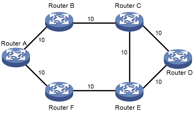
As shown in Figure 1, when no flexible algorithm is configured, all nodes calculate optimal paths by OSPFv3 link cost.
Figure 1 Topology without flexible algorithm 130
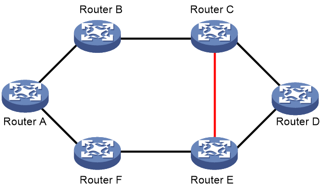
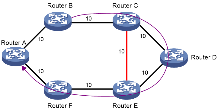
For comparison, you can configure flexible algorithm 130 for all nodes except Router F. The FAD of flexible algorithm 130 is as follows:
· Calculation type—SPF algorithm.
· Metric type—OSPFv3 link cost.
· Constraint—Exclude affinity attribute red.
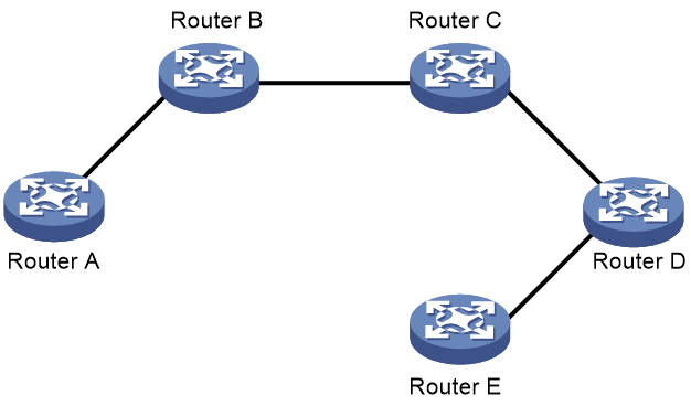
In the new topology shown in Figure 2, all nodes calculate optimal paths based on the calculation type and metric type in the FAD.
Figure 2 Topology with flexible algorithm 130
OSPFv3 flexible algorithm tasks at a glance
To configure IS-IS flexible algorithm, perform the following tasks:
· Configuring the FAD of a flexible algorithm
a. Mapping an affinity attribute name to an affinity bit
b. Assigning affinity attributes to OSPFv3 links
c. Configuring a flexible algorithm
d. Configuring the metric type of a flexible algorithm
· (Optional.) Enhance the reliability of flexible algorithm
¡ Configuring flexible algorithm FRR
¡ Configuring flexible algorithm TI-LFA FRR
¡ Set the priority of an FRR backup path selection policy for flexible algorithm
· Applying a flexible algorithm to SRv6
Prerequisites
Configure SRv6. For more information about SRv6, see SRv6 configuration in Segment Routing Configuration Guide.
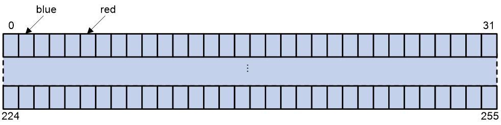
Mapping an affinity attribute name to an affinity bit
About this task
OSPFv3 supports a maximum of 256 affinity bits. They are numbered from 0 to 255. You can perform this task to map different affinity attribute names to these bits. As shown in Figure 3, affinity attribute name blue is mapped to bit 1, and red to bit 5.
This feature enables you to configure affinity attributes for links or define the flexible algorithm topology by specifying only the affinity attribute names.
Figure 3 Mapping an affinity attribute to an affinity bit
Procedure
1. Enter system view.
system-view
2. Enter OSPFv3 view.
ospfv3 [ process-id | vpn-instance vpn-instance-name ] *
3. Map an affinity attribute name to an affinity bit.
affinity-map affinity-name bit-position bit
By default, no affinity attribute name is mapped to an affinity bit.
Assigning affinity attributes to OSPFv3 links
About this task
If you perform this task on an OSPFv3 interface, the links between the interface and its neighbors will carry specific affinity attributes. In a flexible algorithm scenario, these links will be filtered for path calculation based on the link constraints in the FAD.
Procedure
1. Enter system view.
system-view
2. Enter interface view.
interface interface-type interface-number
3. Assign affinity attributes to OSPFv3 links.
ospfv3 affinity flex-algo { affinity-name }&<1-32> [ instance instance-id ]
By default, an OSPFv3 link has no affinity attributes.
Configuring a flexible algorithm
About this task
An OSPFv3 node cannot participate in the path calculation for a flexible algorithm unless you configure the flexible algorithm for the node. To use a flexible algorithm for path calculation, you must make sure a minimum of one node can advertises the FAD of that flexible algorithm in LSAs.
Each node that participates in the path calculation for a flexible algorithm can have a different FAD. To avoid routing loops in an FAD advertisement scope (OSPFv3 area), these nodes must use the same FAD. By convention, a node selects an FAD as follows:
· The FAD with the highest priority will be selected from the FADs advertised within the OSPFv3 routing domain. If the node does not advertise an FAD, it selects the FAD with the highest priority from the received FADs.
· The FAD with the greatest router ID will be selected from the FADs that have the highest priority.
Procedure
system-view
2. Enter OSPFv3 view.
ospfv3 [ process-id | vpn-instance vpn-instance-name ] *
3. Create a flexible algorithm and enter its view.
flex-algo flex-algo-id
4. Configure a priority for the flexible algorithm.
priority priority-value
By default, the priority of a flexible algorithm is 128.
5. Configure the link constraints for a flexible algorithm.
¡ Exclude links that have a minimum of one specified affinity attribute.
affinity exclude-any affinity-name&<1-32>
¡ Include links that have a minimum of one specified affinity attribute.
affinity include-any affinity-name&<1-32>
¡ Include links that have all specified affinity attribute.
affinity include-all affinity-name&<1-32>
By default, all nodes configured to participate in the path calculation for a flexible algorithm are not excluded from the topology.
6. Enable FAD advertisement on a node.
advertise-definition enable
By default, a node does not advertise the FAD.
Configuring the metric type of a flexible algorithm
About metric type configuration for flexible algorithm
By default, the flexible algorithm uses OSPFv3 link cost for optimal path calculation. In some scenarios, the paths calculated by the flexible algorithm might not be optimal. To resolve this issue, configure the flexible algorithm to use another metric type for optimal path calculation.
Flexible algorithm supports the following metric types:
· OSPFv3 link cost.
· Link delay. Flexible algorithm uses the minimum link delay for optimal path calculation.
· MPLS TE metric.
If you specify the metric type of the flexible algorithm as link delay or MPLS TE metric, you need to enable OSPFv3 to advertise application-specific link attribute information, so that the nodes can perform flexible algorithm path calculation. After enabling the function, OSPFv3 uses Application-Specific Link Attributes (ASLA) sub-TLVs to advertise link attributes associated with the flexible algorithm.
Restrictions and guidelines
If the flexible algorithm uses link delay metric, make sure OSPFv3 link delay advertisement is enabled on all interfaces that participate in path calculation for that flexible algorithm.
If the flexible algorithm uses MPLS TE metric, make sure the following requirements are met:
· MPLS TE is enabled for each node that participates in path calculation for that flexible algorithm.
· MPLS and MPLS TE are enabled on each interface that participates in path calculation for that flexible algorithm.
· MPLS TE is enabled for the OSPFv3 area.
The default type values of ASLA Sub-TLVs and End.X SID Sub-TLVs are both 11. To ensure normal operation of Flex-Algo, you must use the segment-routing ipv6 sid-sub-tlv-type command to edit the type value for SRv6 SID-Sub TLVs. This ensures that all SRv6 nodes use the same type value for SRv6 SID-Sub TLVs.
Configuring the metric type as link delay
1. Enter system view.
system-view
ospfv3 [ process-id | vpn-instance vpn-instance-name ] *
3. Enable OSPFv3 to advertise link delay information.
metric-delay advertisement enable
By default, OSPFv3 does not advertise link delay information.
4. E nable OSPFv3 to advertise application-specific link attributes.
advertise application link-attributes te
By default, OSPFv3 does not advertise any application-specific link attributes.
5. Enter flexible algorithm view.
flex-algo flex-algo-id
6. Configure the metric type as link delay.
metric-type delay
By default, the metric type is OSPFv3 link cost.
Configuring the metric type as MPLS TE metric
1. Enter system view.
system-view
2. Enter OSPFv3 view.
ospfv3 [ process-id | vpn-instance vpn-instance-name ] *
3. Enable OSPFv3 to advertise link delay information.
metric-delay advertisement enable
By default, OSPFv3 does not advertise link delay information.
4. (Optional.) Suppress OSPFv3 from advertising link attributes in Intra-Area-TE LSAs.
suppress intra-te link-attributes
By default, OSPFv3 does not suppress advertisement of link attributes in Intra-Area-TE LSAs.
5. Enter flexible algorithm view.
flex-algo flex-algo-id
6. Configure the metric type as TE metric.
metric-type te-cost
By default, the metric type is OSPFv3 link cost.
Configuring flexible algorithm FRR
About this task
The flexible algorithm FRR is similar to OSPFv3 LFA FRR, because it uses LFA to calculate a loop-free backup path with the lowest cost based on the topology.
For illustration, flexible algorithm 130 is configured for all nodes in Figure 4. The FAD of flexible algorithm 130 is as follows:
· Calculation type—SPF algorithm.
· Metric type—OSPFv3 link cost.
· Constraint—Exclude affinity attribute red.
Figure 4 Topology without flexible algorithm 130
In Figure 5, after you enable FRR, flexible algorithm 130 uses LFA to calculate a primary path and a backup path from Router A to Router D.
Figure 5 Topology with flexible algorithm 130
Procedure
1. Enter system view.
system-view
2. Enter OSPFv3 view.
ospfv3 [ process-id | vpn-instance vpn-instance-name ] *
3. Enter flexible algorithm view.
flex-algo flex-algo-id
4. Enable flexible algorithm FRR.
fast-reroute enable
By default, flexible algorithm FRR is enabled.
If no backup paths exist in the network, execute the undo fast-reroute enable command to disable flexible algorithm FRR to save device resources.
Configuring flexible algorithm TI-LFA FRR
About TI-LFA FRR
Topology-Independent Loop-free Alternate Fast Reroute (TI-LFA FRR) is an enhanced version of LFA FRR. TI-LFA FRR uses the same algorithms to calculate P space and Q space as Remote LFA FRR. This feature can protect a topology without PQ nodes.
For more information about P space, Q space and TI-LFA FRR path calculation, see SRv6 configuration in Segment Routing Configuration Guide.
TI-LFA FRR protection types
The following TI-LFA traffic protection types are available:
· Link protection—Protects traffic that traverses a specific link.
· Node protection—Protects traffic that traverses a specific node.
Node protection takes precedence over link protection.
TI-LFA FRR path calculation
TI-LFA FRR uses the common algorithm to calculate backup paths for a flexible algorithm. The only difference is that TI-LFA FRR calculates backup paths for a flexible algorithm according to the FAD and topology of that flexible algorithm.
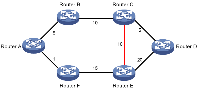
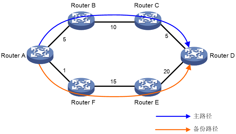
As shown in Figure 6, Router B is the source node and Router A is the destination node.
The number on each link represents the link cost. A data flow traverses from Router B to Router A. To avoid traffic loss against Router B failure, TI-LFA FRR calculates the backup path: Router B > Router C > Router E > Router F > Router A.
Figure 6 TI-LFA FRR backup path calculation without a flexible algorithm
As shown in Figure 7, flexible algorithm 130 is configured for each node. The FAD of flexible algorithm 130 is as follows:
· Calculation type—SPF algorithm.
· Metric type—OSPFv3 link cost.
· Constraint—Exclude affinity attribute red.
In this case, the backup path calculated by TI-LFA FRR is Router B > Router C > Router D > Router E > Router F > Router A.
Figure 7 TI-LFA FRR backup path calculation with a flexible algorithm
Enabling TI-LFA FRR
1. Enter system view.
system-view
2. Enter OSPFv3 view.
ospfv3 [ process-id | vpn-instance vpn-instance-name ] *
3. Enter flexible algorithm view.
flex-algo flex-algo-id
4. Enable TI-LFA FRR.
fast-reroute ti-lfa enable [ per-prefix ]
By default, TI-LFA FRR is enabled.
Set the priority of an FRR backup path selection policy for flexible algorithm
About this task
OSPFv3 flexible algorithm FRR selects a backup path based on the following policies:
· Node-protection policy—Selects the path that involves a specific node.
· Link-protection policy—Selects the path that involves a specific link.
Typically, the cost of a node-protection backup path is higher than that of a link-protection backup path. The link-protection backup path selection policy is known as the lowest-cost backup path selection policy. By default, the node-protection policy takes precedence over the lowest-cost policy. To adjust the priority value of either of the path selection policies as needed, perform this task.
Restrictions and guidelines
If the node-protection policy has a higher priority but the backup path calculation fails, the flexible algorithm uses the lowest-cost policy for further calculation. If the backup path calculation still fails, the flexible algorithm does not perform further backup path calculation.
If the lowest-cost policy has a higher priority but the backup path calculation fails, the flexible algorithm does not perform further backup path calculation.
Procedure
1. Enter system view.
system-view
2. Enter OSPFv3 view.
ospfv3 [ process-id | vpn-instance vpn-instance-name ] *
3. Enter flexible algorithm view.
flex-algo flex-algo-id
4. Set the priority value for an FRR backup path selection policy for a flexible algorithm.
fast-reroute tiebreaker { lowest-cost | node-protecting } preference preference
By default, the priority values of the node-protection and lowest-cost backup path selection policies are 40 and 20, respectively.
Applying a flexible algorithm to SRv6
About this task
With SRv6 enabled, OSPFv3 advertises SRv6 locator TLVs in LSAs. You can identify the algorithm associated to the locator by checking the algorithm field in an SRv6 locator TLV. By default, OSPFv3 uses the SPF algorithm to calculate the shortest path to an SRv6 locator, and the value for the algorithm field is 0.
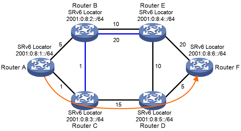
If you associate an SRv6 locator to a flexible algorithm, OSPFv3 uses the flexible algorithm to calculate the shortest path to the locator. For example, you can associate the SRv6 locators in Figure 8 to flexible algorithm 130. The FAD of flexible algorithm 130 is as follows:
· Calculation type—SPF algorithm.
· Metric type—OSPFv3 link cost.
· Constraint—Exclude affinity attribute blue.
As shown in Figure 8, Router A uses the SPF algorithm to calculate the optimal path to locator 2001:0:8:6::/64 based on the topology of flexible algorithm 130.
Figure 8 Optimal path calculated by flexible algorithm 130
Restrictions and guidelines
You must associate an SRv6 locator to a flexible algorithm that already exists, or OSPFv3 will not advertise the locator.
Procedure
1. Enter system view.
system-view
2. Enable SRv6 and enter SRv6 view.
segment-routing ipv6
By default, SRv6 is disabled.
For more information about this command, see SRv6 configuration in Segment Routing Configuration Guide.
3. Configure a locator and enter SRv6 locator view.
locator locator-name [ ipv6-prefix ipv6-address prefix-length [ args args-length | static static-length ] * ]
For more information about this command, see SRv6 configuration in Segment Routing Configuration Guide.
4. Associate the locator to a flexible algorithm.
flex-algo algorithm algo-id
By default, a locator is not associated to any flexible algorithm.
For more information about this command, see SRv6 configuration in Segment Routing Configuration Guide.
Setting OSPFv3 timers
Setting OSPFv3 packet timers
1. Enter system view.
system-view
2. Enter interface view.
interface interface-type interface-number
3. Set the hello interval.
ospfv3 timer hello seconds [ instance instance-id ]
The default hello interval on P2P and broadcast interfaces is 10 seconds. The default hello interval on P2MP and NBMA interfaces is 30 seconds.
4. Set the dead interval.
ospfv3 timer dead seconds [ instance instance-id ]
The default dead interval on P2P and broadcast interfaces is 40 seconds. The default dead interval on P2MP and NBMA interfaces is 120 seconds.
The dead interval set on neighboring interfaces cannot be too short. If the interval is too short, a neighbor is easily down.
5. Set the poll interval.
ospfv3 timer poll seconds [ instance instance-id ]
By default, the poll interval is 120 seconds.
6. Set the LSA retransmission interval.
ospfv3 timer retransmit interval [ instance instance-id ]
The default LSA retransmission interval is 5 seconds.
The LSA retransmission interval cannot be too short. If the interval is too short, unnecessary retransmissions will occur.
Setting LSA transmission delay
About this task
Each LSA in the LSDB has an age that increases by 1 every second, but the age does not change during transmission. Therefore, it is necessary to add a transmission delay into the age time, especially for low-speed links.
Procedure
1. Enter system view.
system-view
2. Enter interface view.
interface interface-type interface-number
3. Set the LSA transmission delay.
ospfv3 trans-delay seconds [ instance instance-id ]
By default, the LSA transmission delay is 1 second.
Setting SPF calculation interval
About this task
LSDB changes result in SPF calculations. When the topology changes frequently, a large amount of network and router resources are occupied by SPF calculation. You can adjust the SPF calculation interval to reduce the impact.
The SPF calculation interval workflow is as follows:
· If no route calculation is triggered within the incremental interval, the minimum interval is used.
· If route calculation is triggered within the incremental interval, the SPF calculation interval increases by the incremental interval × 2n-2 for each calculation until the maximum interval is reached. The value n is the number of consecutive route calculations.
After the maximum interval is reached, SPF calculation is performed at the maximum interval for three consecutive times and then performed at the minimum interval. Then, the SPF calculation interval workflow starts again.
If you execute the spf-schedule-interval maximum-interval minimum-interval incremental-interval conservative command, SPF calculation is always performed at the maximum interval.
In scenarios that require a high route convergence speed, you can execute the spf-schedule-interval millisecond interval command to increase the SPF calculation frequency to accelerate route convergence.
Procedure
1. Enter system view.
system-view
2. Enter OSPFv3 view.
ospfv3 [ process-id | vpn-instance vpn-instance-name ] *
3. Set the SPF calculation interval.
spf-schedule-interval { maximum-interval [ minimum-interval [ incremental-interval [ conservative ] ] ] | millisecond interval }
By default, the maximum interval is 5 seconds, the minimum interval is 50 milliseconds, and the incremental interval is 200 milliseconds.
Setting the LSA arrival interval
About this task
An LSA is a duplicate of a previous LSA if they have the same LSA type, LS ID, and router ID. OSPFv3 drops any duplicate LSAs within the LSA arrival interval.
· After you configure the lsa-arrival-interval maximum-interval command, the LSA arrival interval is maximum-interval. The device drops duplicate LSAs received within the arrival interval.
· After you configure the lsa-arrival-interval maximum-interval minimum-interval command, the arrival interval for the first LSA is minimum-interval. The arrival interval for consequent LSAs is maximum-interval. The device drops duplicate LSAs received within the receiving interval.
· After you configure the lsa-arrival-interval maximum-interval minimum-interval incremental-interval command, the arrival interval for the first LSA is minimum-interval. The arrival interval for the nth (n ≥ 2) LSA is minimum-interval + incremental-interval × 2n-2, and is not greater than maximum-interval. The device drops duplicate LSAs received within the receiving interval.
On a stable network that requires fast convergence, you can set the LSA arrival interval to 0. In this way, OSPF can learn the changes of the topology or routes immediately.
Procedure
1. Enter system view.
system-view
2. Enter OSPFv3 view.
ospfv3 [ process-id | vpn-instance vpn-instance-name ] *
3. Set the LSA arrival interval.
lsa-arrival-interval maximum-interval [ minimum-interval [ incremental-interval ] ]
By default, the maximum interval is 1000 milliseconds, the minimum interval is 500 milliseconds, and the incremental interval is 500 milliseconds.
Setting the LSA generation interval
About this task
You can adjust the LSA generation interval to protect network resources and routers from being over consumed by frequent network changes.
For a stable network, the minimum interval is used. If network changes become frequent, the LSA generation interval increases by the incremental interval × 2n-2 for each generation until the maximum interval is reached. The value n is the number of generation times.
Procedure
1. Enter system view.
system-view
2. Enter OSPFv3 view.
ospfv3 [ process-id | vpn-instance vpn-instance-name ] *
3. Set the LSA generation interval.
lsa-generation-interval maximum-interval [ minimum-interval [ incremental-interval ] ]
By default, the maximum interval is 5 seconds, the minimum interval is 0 milliseconds, and the incremental interval is 0 milliseconds.
Setting the LSU transmit rate
About this task
Sending large numbers of LSU packets affects router performance and consumes a large amount of network bandwidth. You can configure the router to send LSU packets at an interval and to limit the maximum number of LSU packets sent out of an OSPFv3 interface at each interval.
Procedure
1. Enter system view.
system-view
2. Enter OSPFv3 view.
ospfv3 [ process-id | vpn-instance vpn-instance-name ] *
3. Set the LSU transmit rate.
transmit-pacing interval interval count count
By default, an OSPFv3 interface sends a maximum of three LSU packets every 20 milliseconds.
Setting a DR priority for an interface
About this task
The router priority is used for DR election. Interfaces having the priority 0 cannot become a DR or BDR.
Procedure
1. Enter system view.
system-view
2. Enter interface view.
interface interface-type interface-number
3. Set a router priority.
ospfv3 dr-priority priority [ instance instance-id ]
The default router priority is 1.
Configuring OSPFv3 packet parameters
Ignoring MTU check for DD packets
About this task
When LSAs are few in DD packets, it is unnecessary to check the MTU in DD packets to improve efficiency.
Restrictions and guidelines
A neighbor relationship can be established only if the interface's MTU is the same as that of the peer.
Procedure
1. Enter system view.
system-view
2. Enter interface view.
interface interface-type interface-number
3. Ignore MTU check for DD packets.
ospfv3 mtu-ignore [ instance instance-id ]
By default, OSPFv3 does not ignore MTU check for DD packets.
Setting the DSCP value for outgoing OSPFv3 packets
About this task
The DSCP value specifies the precedence of outgoing packets.
Procedure
1. Enter system view.
system-view
2. Enter OSPFv3 view.
ospfv3 [ process-id | vpn-instance instance-name ] *
3. Set the DSCP value for outgoing OSPFv3 packets.
dscp dscp-value
By default, the DSCP value for outgoing OSPFv3 packets is 48.
Disabling interfaces from receiving and sending OSPFv3 packets
About this task
After an OSPFv3 interface is set to silent, direct routes of the interface can still be advertised in Intra-Area-Prefix LSAs through other interfaces, but other OSPFv3 packets cannot be advertised. No neighboring relationship can be established on the interface. This feature can enhance the adaptability of OSPFv3 networking.
Restrictions and guidelines
You can execute either the silent-interface or ospfv3 silent command or both commands for an interface to achieve the same effect. Choose an appropriate configuration method as needed.
Disabling interfaces from receiving and sending OSPFv3 packets in OSPFv3 view
1. Enter system view.
system-view
2. Enter OSPFv3 view.
ospfv3 [ process-id | vpn-instance vpn-instance-name ] *
3. Disable interfaces from receiving and sending OSPFv3 packets.
silent-interface { interface-type interface-number | all }
By default, the interfaces can receive and send OSPFv3 packets.
This command disables only the interfaces that run the current process. However, multiple OSPFv3 processes can disable the same interface from receiving and sending OSPFv3 packets.
Disabling an interface from receiving and sending OSPFv3 packets in interface view
1. Enter system view.
system-view
2. Enter interface view.
interface interface-type interface-number
3. Disable an interface from receiving and sending OSPFv3 packets.
ospfv3 silent
By default, an interface can receive and send OSPFv3 packets.
Accelerating OSPFv3 convergence speed
Configuring OSPFv3 ISPF
About this task
Incremental SPF (ISPF) allows the system to recalculate nodes affected by topology changes rather than the entire OSPFv3 shortest path tree. OSPFv3 ISPF saves CPU resources caused by SPF calculations and accelerates the convergence speed.
Procedure
1. Enter system view.
system-view
2. Enter OSPFv3 view.
ospfv3 [ process-id | vpn-instance vpn-instance-name ] *
3. Enable OSPFv3 ISPF.
ispf enable
By default, OSPFv3 ISPF is enabled.
Configuring prefix suppression
About this task
By default, an OSPFv3 interface advertises all of its prefixes in LSAs. To speed up OSPFv3 convergence, you can suppress interfaces from advertising all of their prefixes. This feature helps improve network security by preventing IP routing to the suppressed networks.
When prefix suppression is enabled:
· OSPFv3 does not advertise the prefixes of suppressed interfaces in Type-8 LSAs.
· On broadcast and NBMA networks, the DR does not advertise the prefixes of suppressed interfaces in Type-9 LSAs that reference Type-2 LSAs.
· On P2P and P2MP networks, OSPFv3 does not advertise the prefixes of suppressed interfaces in Type-9 LSAs that reference Type-1 LSAs.
Restrictions and guidelines for prefix suppression
As a best practice, configure prefix suppression on all OSPFv3 routers if you want to use prefix suppression.
Configuring prefix suppression for an OSPFv3 process
1. Enter system view.
system-view
2. Enter OSPFv3 view.
ospfv3 [ process-id | vpn-instance vpn-instance-name ] *
3. Enable prefix suppression for the OSPFv3 process.
prefix-suppression
By default, prefix suppression is disabled for an OSPFv3 process.
Enabling prefix suppression for an OSPFv3 process does not suppress the prefixes of loopback interfaces and passive interfaces.
Configuring prefix suppression for an interface
1. Enter system view.
system-view
2. Enter interface view.
interface interface-type interface-number
3. Enable prefix suppression for the interface.
ospfv3 prefix-suppression [ disable ] [ instance instance-id ]
By default, prefix suppression is disabled for an interface.
Configuring PIC
About this task
Prefix Independent Convergence (PIC) enables the device to converge without the dependence on the number of prefixes. The convergence time does not increase as the number of prefixes in the routing table increases.
Restrictions and guidelines for OSPFv3 PIC
When both OSPFv3 PIC and OSPFv3 FRR are configured, OSPFv3 FRR takes effect.
OSPFv3 PIC applies only to inter-area routes and external routes.
Enabling PIC
1. Enter system view.
system-view
2. Enter OSPFv3 view.
ospfv3 [ process-id | vpn-instance instance-name ] *
3. Enable PIC for OSPFv3.
pic [ additional-path-always ]
By default, OSPFv3 PIC is disabled.
Configuring BFD OSPFv3 PIC (control packet mode)
1. Enter system view.
system-view
2. Enter interface view.
interface interface-type interface-number
3. Enable BFD control packet mode for OSPFv3 PIC.
ospfv3 primary-path-detect bfd ctrl [ instance instance-id ]
By default, BFD control packet mode is disabled for OSPFv3 PIC.
To speed up OSPFv3 convergence, enable BFD control packet mode for OSPFv3 PIC to detect the primary link failures. This mode requires BFD configuration on both OSPFv3 routers on the link.
Configuring BFD for OSPFv3 PIC (echo packet mode)
1. Enter system view.
system-view
2. (Optional.) Configure the source IPv6 address of BFD echo packets.
bfd echo-source-ipv6 ipv6-address
By default, the source IPv6 address of BFD echo packets is not configured.
As a best practice to avoid network congestion caused by massive ICMPv6 redirect packets from the remote end, execute this command and specify a source IPv6 address that is not on the same network segment as any local interface's IP address.
For more information about this command, see High Availability Command Reference.
3. Enter interface view.
interface interface-type interface-number
4. Enable BFD echo packet mode for OSPFv3 PIC.
ospfv3 primary-path-detect bfd echo [ instance instance-id ]
By default, BFD echo packet mode is disabled for OSPFv3 PIC.
To speed up OSPFv3 convergence, enable BFD single-hop echo packet mode for OSPFv3 PIC to detect the primary link failures. This mode requires BFD configuration on one OSPFv3 router on the link.
Configuring OSPFv3 advanced features
Configuring a stub router
About this task
A stub router is used for traffic control. It reports its status as a stub router to neighboring OSPFv3 routers. The neighboring routers can have a route to the stub router, but they do not use the stub router to forward data.
Use either of the following methods to configure a router as a stub router:
· Clear the R-bit of the Option field in Type-1 LSAs. When the R-bit is clear, the OSPFv3 router can participate in OSPFv3 topology distribution without forwarding traffic.
· Use the OSPFv3 max-metric router LSA feature. This feature enables OSPFv3 to advertise its locally generated Type-1 LSAs with a maximum cost of 65535. Neighbors do not send packets to the stub router as long as they have a route with a smaller cost.
Procedure
1. Enter system view.
system-view
2. Enter OSPFv3 view.
ospfv3 [ process-id | vpn-instance vpn-instance-name ] *
3. Configure the router as a stub router.
¡ Configure the router as a stub router and clear the R-bit of the Option field in Type-1 LSAs.
stub-router r-bit [ include-stub | on-startup { seconds | wait-for-bgp [ seconds ] } ] *
¡ Configure the router as a stub router and advertise the locally generated Type-1 LSAs with the maximum cost of 65535.
stub-router max-metric [ external-lsa [ max-metric-value ] | summary-lsa [ max-metric-value ] | include-stub | on-startup { seconds | wait-for-bgp [ seconds ] } ] *
By default, the router is not configured as a stub router.
A stub router is not related to a stub area.
Configuring OSPFv3 isolation
About this task
Isolation is a method used for network device maintenance. It gracefully removes a device from the packet forwarding path for maintenance and gracefully adds the device to the network after maintenance.
To reduce impact on traffic forwarding, you can isolate a device before upgrading it. OSPFv3 isolation works as follows:
1. After OSPFv3 isolation is enabled for a device, OSPFv3 increases the link cost in LSAs advertised by the device based on the following rules:
¡ The link cost in Type-1 LSAs (Router LSAs) is set to 65535.
¡ The link cost in Type-9 LSAs (Intra-area-prefix LSAs) that reference Type-1 LSAs is set to 65535.
¡ The link cost in the following LSAs is set to 16711680:
- Type-3 LSAs (Inter-area-prefix LSAs).
- Type-4 LSAs (Inter-area-router LSAs).
- Type-5 LSAs (AS external LSAs).
- Type-7 LSAs (NSSA LSAs).
2. Each neighbor of the device reselects an optimal route based on the LSAs and stops forwarding traffic to the device. The device is fully isolated from the network and you can upgrade the device.
3. After the maintenance, disable OSPFv3 isolation on the device to restore its link cost and gracefully add it back to the network.
Procedure
1. Enter system view.
system-view
2. Enter OSPFv3 view.
ospfv3 [ process-id | vpn-instance vpn-instance-name ] *
3. Configure OSPFv3 isolation.
¡ Enable OSPFv3 isolation to gracefully isolate the device from the network.
isolate enable
¡ Disable OSPFv3 isolation to gracefully add the device back to the network.
undo isolate enable
By default, OSPFv3 isolation is disabled.
Configuring OSPFv3 shutdown
About this task
For maintenance purposes, you can use this feature to shut down processes on the device with small impact on the network. If you shut down an OSPFv3 process, it will perform the following operations:
· Send 1-way hello packets to its neighbors.
On receipt of the packets, the neighbors disconnect from the process and use the backup path to forward traffic.
· Stop receiving and sending OSPFv3 packets.
· Clear its neighbor, LSDB, and OSPFv3 route information.
After maintenance, you can use the undo shutdown process command to restart the process for neighbor relationship re-establishment.
This feature shuts down an OSPFv3 process while retaining the process-associated settings to facilitate your maintenance.
Procedure
1. Enter system view.
system-view
2. Enter OSPFv3 view.
ospfv3 [ process-id | vpn-instance vpn-instance-name ] *
3. Configure OSPFv3 shutdown.
a. Shut down an OSPFv3 process to isolate it from the network.
shutdown process
b. Restart the OSPFv3 process to add it back to the network.
undo shutdown process
By default, the OSPFv3 process is not shut down.
Configuring the virtual system feature
About this task
In an AS, each OSPFv3 node has a unique router ID and can manage multiple OSPFv3 interfaces. The IPv6 addresses of the interfaces managed by the same OSPFv3 node cannot reside on the same network segment.
Procedure
1. Enter system view.
system-view
2. Enter OSPFv3 view.
ospfv3 [ process-id | vpn-instance vpn-instance-name ] *
3. Enable the virtual system feature for the OSPFv3 process.
virtual-system enable
By default, the virtual system feature is disabled.
4. Return to system view.
quit
5. Enter interface view.
interface interface-type interface-number
6. Enable the virtual system feature on the OSPFv3 interface.
ospfv3 virtual-system router-id router-id
By default, the virtual system feature is disabled.
Configuring OSPFv3 GR
About OSPFv3 GR
GR ensures forwarding continuity when a routing protocol restarts or an active/standby switchover occurs.
Two routers are required to complete a GR process. The following are router roles in a GR process:
· GR restarter—Graceful restarting router. It must be Graceful Restart capable.
· GR helper—The neighbor of the GR restarter. It helps the GR restarter to complete the GR process.
To prevent service interruption after a master/backup switchover, a GR restarter running OSPFv3 must perform the following tasks:
· Keep the GR restarter forwarding entries stable during reboot.
· Establish all adjacencies and obtain complete topology information after reboot.
After the active/standby switchover, the GR restarter sends a Grace LSA to tell its neighbors that it performs a GR. Upon receiving the Grace LSA, the neighbors with the GR helper capability enter the helper mode (and are called GR helpers). Then, the GR restarter retrieves its adjacencies and LSDB with the help of the GR helpers.
Configuring GR restarter
1. Enter system view.
system-view
2. Enter OSPFv3 view.
ospfv3 [ process-id | vpn-instance vpn-instance-name ] *
3. Enable the GR capability.
graceful-restart enable [ global | planned-only ] *
By default, OSPFv3 GR restarter capability is disabled.
4. (Optional.) Set the GR interval.
graceful-restart interval interval
By default, the GR interval is 120 seconds.
Configuring GR helper
1. Enter system view.
system-view
2. Enter OSPFv3 view.
ospfv3 [ process-id | vpn-instance vpn-instance-name ] *
3. Enable the GR helper capability.
graceful-restart helper enable [ planned-only ]
By default, the GR helper capability is enabled.
4. Enable strict LSA checking.
graceful-restart helper strict-lsa-checking
By default, strict LSA checking is disabled.
Triggering OSPFv3 GR
About this task
OSPFv3 GR is triggered by an active/standby switchover or when this task is performed.
Procedure
To trigger OSPFv3 GR, execute the reset ospfv3 [ process-id ] process graceful-restart command in user view.
Configuring BFD for OSPFv3
About this task
Bidirectional forwarding detection (BFD) provides a mechanism to quickly detect the connectivity of links between OSPFv3 neighbors, improving the convergence speed of OSPFv3. For more information about BFD, see High Availability Configuration Guide.
After discovering neighbors by sending hello packets, OSPFv3 notifies BFD of the neighbor addresses, and BFD uses these addresses to establish sessions. Before a BFD session is established, it is in the down state. In this state, BFD control packets are sent at an interval of no less than 1 second to reduce BFD control packet traffic. After the BFD session is established, BFD control packets are sent at the negotiated interval, thereby implementing fast fault detection.
To configure BFD for OSPFv3, you need to configure OSPFv3 first.
Configuring BFD for OSPFv3
1. Enter system view.
system-view
2. Enter OSPFv3 view.
ospfv3 [ process-id | vpn-instance vpn-instance-name ] *
3. Specify a router ID.
router-id router-id
4. Quit the OSPFv3 view.
quit
5. Enter interface view.
interface interface-type interface-number
6. Enable an OSPFv3 process on the interface.
ospfv3 process-id area area-id [ instance instance-id ]
7. Enable BFD on the interface.
ospfv3 bfd enable [ instance instance-id ]
By default, BFD is disabled on the OSPFv3 interface.
Enabling OSPFv3 to adjust the interface cost according to the BFD session state
About this task
After you enable BFD for OSPFv3, the OSPFv3 neighbor relationship goes down when the BFD session is down and comes up when the BFD session is up. When the BFD session state changes frequently, OSPFv3 neighbor relationship flapping will occur and traffic forwarding might be affected.
To resolve this issue, enable OSPFv3 to adjust the interface cost according to the BFD session state.
After you execute this command on an interface, OSPFv3 adjusts the interface cost as follows:
· When the BFD session on the interface goes down, OSPFv3 increases the cost value for the interface.
· When the BFD session on the interface comes up, OSPFv3 restores the cost value for the interface.
Procedure
1. Enter system view.
system-view
2. Enter interface OSPFv3 view.
interface interface-type interface-number
3. Enable OSPFv3 to adjust the interface cost according to the BFD session state.
ospfv3 bfd adjust-cost { cost-offset | max } [ instance instance-id ]
By default, OSPFv3 does not adjust the interface cost according to the BFD session state.
Suppressing interface cost adjustment according to the BFD session state upon BFD session flapping
About this task
After you enable OSPFv3 to adjust the interface cost according to the BFD session state, if BFD session flaps frequently, the following conditions might occur:
· The OSPFv3 interface cost changes frequently, resulting in repeated route calculations that greatly consume device resources.
· When the BFD session state changes from down to up, OSPFv3 immediately resumes the original interface cost. If the link becomes unavailable again in a short time, packet loss will occur on this link before route convergence.
You can configure this feature to address the previous issues. When the BFD session state changes, OSPFv3 performs the following operations instead of immediately adjusting the interface cost:
· When the BFD session state changes from up to down, OSPFv3 starts a BFD session state detection timer, and records one BFD session down event. If the number of BFD session down events crosses the threshold within the detection interval, OSPFv3 adjusts the interface cost based on configuration of the ospfv3 bfd adjust-cost command. (The threshold is specified with the threshold keyword. The detection interval is specified with the detect-interval argument.) If this condition is not met, OSPFv3 does not adjust the interface cost.
· After OSPFv3 adjusts the interface cost (based on the configuration of the ospfv3 bfd adjust-cost command), it starts a delay timer when the BFD session state changes from down to up. Before expiration of the delay timer (specified with the resume-interval argument), the following conditions will occur:
¡ If the BFD session remains up, OSPFv3 resumes the original interface cost when the delay timer expires.
¡ If the BFD session state changes from up to down, OSPFv3 deletes the delay timer and does not resume the original interface cost.
Restrictions and guidelines
This command takes effect only after you configure the ospfv3 bfd adjust-cost command.
Procedure
1. Enter system view.
system-view
2. Enter interface view.
interface interface-type interface-number
3. Suppress adjustment of the interface cost according to the BFD session state upon BFD session flapping.
ospfv3 bfd adjust-cost suppress-flapping { detect-interval detect-interval | resume-interval resume-interval | threshold threshold } *
By default, OSPFv3 does not suppress adjustment of the interface cost according to the BFD session state upon BFD session flapping.
Configuring OSPFv3 FRR
About OSPFv3 FRR
A primary link failure can cause packet loss and even a routing loop until OSPFv3 completes routing convergence based on the new network topology. OSPFv3 FRR enables fast rerouting to minimize the failover time.
Figure 9 Network diagram for OSPFv3 FRR
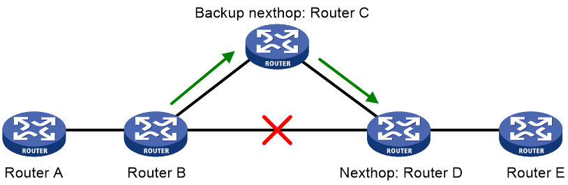
As shown in Figure 9, configure FRR on Router B. OSPFv3 FRR automatically calculates a backup next hop or specifies a backup next hop by using a routing policy. When the primary link fails, OSPFv3 directs packets to the backup next hop. At the same time, OSPFv3 calculates the shortest path based on the new network topology. It forwards packets over the path after network convergence.
You can configure OSPFv3 FRR to calculate a backup next hop by using the loop free alternate (LFA) algorithm, or specify a backup next hop by using a routing policy.
Configuring OSPFv3 FRR to use the LFA algorithm to calculate a backup next hop
Restrictions and guidelines
Do not use the fast-reroute lfa command together with the vlink-peer command.
Procedure
1. Enter system view.
system-view
2. Enter interface view.
interface interface-type interface-number
3. (Optional.) Disable LFA on an interface.
ospfv3 fast-reroute lfa-backup exclude
By default, the interface on which LFA is enabled can be selected as a backup interface.
4. Return to system view.
quit
5. Enter OSPFv3 view.
ospfv3 [ process-id | vpn-instance vpn-instance-name ] *
6. Enable OSPFv3 FRR to use the LFA algorithm to calculate a backup next hop.
fast-reroute lfa [ abr-only | ecmp-shared ]
By default, OSPFv3 FRR is disabled.
If abr-only is specified, the route to the ABR is selected as the backup path.
Configuring OSPFv3 FRR to use a backup next hop in a routing policy
About this task
Before you perform this task, use the apply ipv6 fast-reroute backup-interface command to specify a backup next hop in the routing policy to be used. For more information about the apply ipv6 fast-reroute backup-interface command and routing policy configuration, see "Configuring routing policies."
Procedure
1. Enter system view.
system-view
2. Enter interface view.
interface interface-type interface-number
3. (Optional.) Disable LFA on an interface.
ospfv3 fast-reroute lfa-backup exclude
By default, the interface is enabled with LFA and it can be selected as a backup interface.
4. Return to system view.
quit
5. Enter OSPFv3 view.
ospfv3 [ process-id | vpn-instance vpn-instance-name ] *
6. Configure OSPFv3 FRR to use a backup next hop in a routing policy.
fast-reroute route-policy route-policy-name
By default, OSPFv3 FRR is disabled.
Setting the priority for FRR backup path selection policies
About this task
OSPFv3 FRR uses specific policies for backup path calculation. This command defines the priority for the backup path selection policy. The higher the value, the higher the priority of the associated backup path selection policy. Changing the backup path selection policy priority can affect the backup path calculation result for OSPFv3 FRR. The backup paths can provide node protection or link protection for traffic, or provide both node protection and link protection.
OSPFv3 FRR supports the following backup path selection policies that are used to generate different topologies for backup path calculation:
· Node protection—OSPFv3 FRR performs backup path calculation after excluding the primary next hop node.
· Lowest cost—OSPFv3 FRR performs backup path calculation after excluding the direct primary link.
If multiple backup path selection policies exist in an OSPFv3 process, the policy with the highest priority is used to calculate the backup path. If the policy fails to calculate the backup path, another policy with higher priority is used. OSPFv3 performs backup path calculation by using the node protection and lowest cost policies as follows:
· If the node protection policy has higher priority and fails to calculate the backup path, OSPFv3 uses the lowest cost policy to calculate the backup path. If the lowest cost policy still fails to calculate the backup path, reliability cannot be ensured upon primary link failure.
· If the lowest cost policy has higher priority and fails to calculate the backup path, OSPFv3 does not perform further backup path calculation with the node protection policy. Reliability cannot be ensured upon primary link failure.
Procedure
1. Enter system view.
system-view
2. Enter OSPFv3 view.
ospfv3 [ process-id | vpn-instance vpn-instance-name ] *
3. Set the priority for a backup path selection policy.
fast-reroute tiebreaker { lowest-cost | node-protecting } preference preference
By default, the priority values of the node-protection and lowest-cost backup path selection policies are 40 and 20, respectively.
Configuring BFD control packet mode for OSPFv3 FRR
About this task
By default, OSPFv3 FRR does not use BFD to detect primary link failures. To speed up OSPFv3 convergence, enable BFD control packet mode for OSPFv3 FRR to detect primary link failures. This mode requires BFD configuration on both OSPFv3 routers on the link.
Procedure
1. Enter system view.
system-view
2. Enter interface view.
interface interface-type interface-number
3. Enable BFD control packet mode for OSPFv3 FRR.
ospfv3 primary-path-detect bfd ctrl [ instance instance-id ]
By default, BFD control packet mode is disabled for OSPFv3 FRR.
Configuring BFD echo packet mode for OSPFv3 FRR
About this task
By default, OSPFv3 FRR does not use BFD to detect primary link failures. To speed up OSPFv3 convergence, enable BFD echo packet mode for OSPFv3 FRR to detect primary link failures. This mode requires BFD configuration on one OSPFv3 router on the link.
Procedure
1. Enter system view.
system-view
2. (Optional.) Configure the source IPv6 address of BFD echo packets.
bfd echo-source-ipv6 ipv6-address
By default, the source IPv6 address of BFD echo packets is not configured.
As a best practice to avoid network congestion caused by massive ICMPv6 redirect packets from the remote end, execute this command and specify a source IPv6 address that is not on the same network segment as any local interface's IP address.
For more information about this command, see High Availability Command Reference.
3. Enter interface view.
interface interface-type interface-number
4. Enable BFD echo packet mode for OSPFv3 FRR.
ospfv3 primary-path-detect bfd echo [ instance instance-id ]
By default, BFD echo packet mode is disabled for OSPFv3 FRR.
Enhancing OSPFv3 security
Configuring OSPFv3 authentication
About this task
OSPFv3 uses keychain authentication to prevent routing information from being leaked and routers from being attacked.
OSPFv3 adds the Authentication Trailer option into outgoing packets, and uses the authentication information in the option to authenticate incoming packets. Only packets that pass the authentication can be received. If a packet fails the authentication, the OSPFv3 neighbor relationship cannot be established.
Restrictions and guidelines
The authentication mode specified for an OSPFv3 interface has a higher priority than the mode specified for the OSPFv3 area to which that OSPFv3 interface belongs.
Configuring OSPFv3 area authentication
1. Enter system view.
system-view
2. Enter OSPFv3 view.
ospfv3 [ process-id | vpn-instance vpn-instance-name ] *
3. Enter OSPFv3 area view.
area area-id
4. Specify an authentication mode for the area. Choose one option as needed:
¡ Configure the area to use HMAC-SHA-256/HMAC-SM3 authentication.
authentication-mode { hmac-sha-256 | hmac-sm3 } key-id { cipher | plain } string
¡ Configure the area to use keychain authentication.
authentication-mode keychain keychain-name
For more information about keychains, see keychain configuration in Security Configuration Guide.
By default, no authentication is performed for the area.
All routers in an area must use the same authentication mode and the same key.
Configuring OSPFv3 interface authentication
1. Enter system view.
system-view
2. Enter interface view.
interface interface-type interface-number
3. Specify an authentication mode for the interface. Choose one option as needed:
¡ Configure the interface to use HMAC-SHA-256/HMAC-SM3 authentication.
ospfv3 authentication-mode { hmac-sha-256 | hmac-sm3 } key-id { cipher | plain } string [ instance instance-id ]
¡ Configure the interface to use keychain authentication.
ospfv3 authentication-mode keychain keychain-name [ instance instance-id ]
For more information about keychains, see keychain configuration in Security Configuration Guide.
By default, no authentication is performed for the interface.
All interfaces on a network must use the same authentication mode and the same key.
Applying an IPsec profile for authenticating OSPFv3 packets
About this task
To protect routing information and prevent attacks, OSPFv3 can authenticate protocol packets by using an IPsec profile. For more information about IPsec profiles, see Security Configuration Guide.
Outbound OSPFv3 packets carry the Security Parameter Index (SPI) defined in the relevant IPsec profile. A device compares the SPI carried in a received packet with the configured IPsec profile. If they match, the device accepts the packet. Otherwise, the device discards the packet and will not establish a neighbor relationship with the sending device.
Restrictions and guidelines for applying an IPsec profile
You can configure an IPsec profile for an area, an interface, a virtual link, or a sham link.
· To implement area-based IPsec protection, configure the same IPsec profile on the routers in the target area.
· To implement interface-based IPsec protection, configure the same IPsec profile on the interfaces between two neighboring routers.
· To implement virtual link-based IPsec protection, configure the same IPsec profile on the two routers connected over the virtual link.
· To implement sham link-based IPsec protection, configure the same IPsec profile on the two routers connected over the sham link. For more information about sham links, see MPLS Configuration Guide.
· If an interface and its area each have an IPsec profile configured, the interface uses its own IPsec profile.
· If a virtual link and area 0 each have an IPsec profile configured, the virtual link uses its own IPsec profile.
· If a sham link and its area have an IPsec profile configured, the sham link uses its own IPsec profile.
Applying an IPsec profile to an area
1. Enter system view.
system-view
2. Enter OSPFv3 view.
ospfv3 [ process-id | vpn-instance vpn-instance-name ] *
3. Enter OSPFv3 area view.
area area-id
4. Apply an IPsec profile to the area.
enable ipsec-profile profile-name
By default, no IPsec profile is applied.
Applying an IPsec profile to an interface
1. Enter system view.
system-view
2. Enter interface view.
interface interface-type interface-number
3. Apply an IPsec profile to the interface.
ospfv3 ipsec-profile profile-name [ instance instance-id ]
By default, no IPsec profile is applied.
Applying an IPsec profile to a virtual link
1. Enter system view.
system-view
2. Enter OSPFv3 view.
ospfv3 [ process-id | vpn-instance vpn-instance-name ] *
3. Enter OSPFv3 area view.
area area-id
4. Apply an IPsec profile to a virtual link.
vlink-peer router-id [ dead seconds | hello seconds | instance instance-id | ipsec-profile profile-name | keychain keychain-name | retransmit seconds | trans-delay seconds ] *
By default, no IPsec profile is applied.
Applying an IPsec profile to a sham link
1. Enter system view.
system-view
2. Enter OSPFv3 view.
ospfv3 [ process-id | vpn-instance vpn-instance-name ] *
3. Enter OSPFv3 area view.
area area-id
4. Apply an IPsec profile to a sham link.
sham-link source-ipv6-address destination-ipv6-address [ cost cost-value | dead dead-interval | hello hello-interval | instance instance-id | ipsec-profile profile-name | keychain keychain-name | retransmit retrans-interval | trans-delay delay ] *
By default, no IPsec profile is applied.
Configuring OSPFv3 logging and SNMP notifications
Enabling logging for neighbor state changes
About this task
With this feature enabled, the router delivers logs about neighbor state changes to its information center. The information center processes logs according to user-defined output rules (whether to output logs and where to output). For more information about the information center, see Network Management and Monitoring Configuration Guide.
Procedure
1. Enter system view.
system-view
2. Enter OSPFv3 view.
ospfv3 [ process-id | vpn-instance vpn-instance-name ] *
3. Enable logging for neighbor state changes.
log-peer-change
By default, this feature is enabled.
Setting the maximum number of OSPFv3 logs
About this task
OSPFv3 logs include route calculation logs, neighbor logs, and LSA aging logs.
Procedure
1. Enter system view.
system-view
2. Enter OSPFv3 view.
ospfv3 [ process-id | vpn-instance vpn-instance-name ] *
3. Set the maximum number of OSPFv3 logs.
event-log { lsa-flush | peer | spf } size count
By default, the maximum number of LSA aging logs, neighbor logs, or route calculation logs is 10.
Configuring OSPFv3 network management
About this task
This task involves the following configurations:
· Bind an OSPFv3 process to MIB so that you can use network management software to manage the specified OSPFv3 process.
· Enable SNMP notifications for OSPFv3 to report important events.
· Set the SNMP notification output interval and the maximum number of SNMP notifications that can be output at each interval.
To report critical OSPFv3 events to an NMS, enable SNMP notifications for OSPFv3. For SNMP notifications to be sent correctly, you must also configure SNMP on the device. For more information about SNMP configuration, see the network management and monitoring configuration guide for the device.
The standard OSPFv3 MIB provides only single-instance MIB objects. To identify multiple OSPFv3 processes in the standard OSPFv3 MIB, you must assign a unique context name to each OSPFv3 process.
Context is a method introduced to SNMPv3 for multiple-instance management. For SNMPv1/v2c, you must specify a community name as a context name for protocol identification.
Procedure
1. Enter system view.
system-view
2. Bind MIB to an OSPFv3 process.
ospfv3 mib-binding process-id
By default, MIB is bound to the process with the smallest process ID.
3. Enable SNMP notifications for OSPFv3.
snmp-agent trap enable ospfv3 [ grhelper-status-change | grrestarter-status-change | if-bad-pkt | if-cfg-error | if-state-change | last-auth-key-expiry | neighbor-state-change | nssatranslator-status-change | virtgrhelper-status-change | virtif-bad-pkt | virtif-cfg-error | virtif-state-change | virtneighbor-state-change ] *
By default, SNMP notifications for OSPFv3 are enabled.
4. Enter OSPFv3 view.
ospfv3 [ process-id | vpn-instance vpn-instance-name ] *
5. Configure an SNMP context for the OSPFv3 process.
snmp context-name context-name
By default, no SNMP context is configured for the OSPFv3 process.
6. (Optional.) Set the SNMP notification output interval and the maximum number of SNMP notifications that can be output at each interval.
snmp trap rate-limit interval trap-interval count trap-number
By default, OSPFv3 outputs a maximum of seven SNMP notifications within 10 seconds.
Display and maintenance commands for OSPFv3
Execute display commands in any view and reset commands in user view.
|
Task |
Command |
|
Display information about the routes to OSPFv3 ABR and ASBR. |
display ospfv3 [ process-id ] abr-asbr |
|
Display summary route information on the OSPFv3 ABR. |
display ospfv3 [ process-id ] [ area area-id ] abr-summary [ ipv6-address prefix-length ] [ verbose ] |
|
Display information about the SPF tree calculated by a flexible algorithm for an OSPFv3 area. |
display ospfv3 [ process-id ] [ area area-id ] flex-algo flex-algo-id spf-tree [ verbose ] |
|
Display information about the FADs received or advertised by a node. |
display ospfv3 [ process-id ] [ area area-id ] global-flex-algo [ algorithm-id flex-algo-id ] |
|
Display summary route information on the OSPFv3 ASBR. |
display ospfv3 [ process-id ] asbr-summary [ ipv6-address prefix-length ] [ verbose ] |
|
Display OSPFv3 log information. |
display ospfv3 [ process-id ] event-log { lsa-flush | peer | spf } |
|
Display information about routes calculated by a flexible algorithm. |
display ospfv3 [ process-id ] flex-algo flex-algo-id routing [ ipv6-address prefix-length ] |
|
Display OSPFv3 process information. |
display ospfv3 [ process-id ] [ verbose ] |
|
Display OSPFv3 GR information. |
display ospfv3 [ process-id ] graceful-restart [ verbose ] |
|
Display OSPFv3 NSR information. |
display ospfv3 [ process-id ] non-stop-routing |
|
Display OSPFv3 interface information. |
display ospfv3 [ process-id ] interface [ interface-type interface-number | verbose ] |
|
Display the configuration for a flexible algorithm on a node. |
display ospfv3 [ process-id ] local-flex-algo [ algorithm-id flex-algo-id ] |
|
Display OSPFv3 LSDB information. |
display ospfv3 [ process-id ] lsdb [ { external | grace | inter-prefix | inter-router | intra-prefix | intra-te | link | network | nssa | router | unknown [ type ] } [ link-state-id ] [ originate-router router-id | self-originate ] | statistics | total | verbose ] |
|
Display OSPFv3 next hop information. |
display ospfv3 [ process-id ] nexthop |
|
Display OSPFv3 neighbor information. |
display ospfv3 [ process-id ] [ area area-id ] peer [ [ interface-type interface-number ] [ verbose ] | peer-router-id | statistics ] |
|
Display OSPFv3 request list information. |
display ospfv3 [ process-id ] [ area area-id ] request-queue [ interface-type interface-number ] [ neighbor-id ] |
|
Display OSPFv3 retransmission list information. |
display ospfv3 [ process-id ] [ area area-id ] retrans-queue [ interface-type interface-number ] [ neighbor-id ] |
|
Display OSPFv3 routing information. |
display ospfv3 [ process-id ] routing [ ipv6-address prefix-length ] |
|
Display OSPFv3 SPF tree information. |
display ospfv3 [ process-id ] [ area area-id ] spf-tree [ verbose ] |
|
Display OSPFv3 statistics. |
display ospfv3 [ process-id ] statistics [ error ] |
|
Display OSPFv3 virtual link information. |
display ospfv3 [ process-id ] vlink |
|
Display global OSPFv3 statistics. |
display ospfv3 global-statistics [ public | vpn-instance vpn-instance-name ] |
|
Restart an OSPFv3 process. |
reset ospfv3 [ process-id ] process [ graceful-restart ] |
|
Restart OSPFv3 route redistribution. |
reset ospfv3 [ process-id ] redistribution |
|
Clear OSPFv3 statistics. |
reset ospfv3 [ process-id ] statistics |
|
Clear OSPFv3 log information. |
reset ospfv3 [ process-id ] event-log [ lsa-flush | peer | spf ] |
OSPFv3 configuration examples
Example: Configuring OSPFv3 stub area
Network configuration
As shown in Figure 10:
· Enable OSPFv3 on all routers.
· Split the AS into three areas.
· Configure Router B and Router C as ABRs to forward routing information between areas.
· Configure Area 2 as a stub area to reduce LSAs in the area without affecting route reachability.

Procedure
1. Configure IPv6 addresses for interfaces. (Details not shown.)
2. Configure basic OSPFv3:
# On Router A, enable OSPFv3 and specify the router ID as 1.1.1.1.
<RouterA> system-view
[RouterA] ospfv3 1
[RouterA-ospfv3-1] router-id 1.1.1.1
[RouterA-ospfv3-1] quit
[RouterA] interface ten-gigabitethernet 3/1/1
[RouterA-Ten-GigabitEthernet3/1/1] ospfv3 1 area 1
[RouterA-Ten-GigabitEthernet3/1/1] quit
[RouterA] interface ten-gigabitethernet 3/1/2
[RouterA-Ten-GigabitEthernet3/1/2] ospfv3 1 area 1
[RouterA-Ten-GigabitEthernet3/1/2] quit
# On Router B, enable OSPFv3 and specify the router ID as 2.2.2.2.
<RouterB> system-view
[RouterB] ospfv3 1
[RouterB-ospfv3-1] router-id 2.2.2.2
[RouterB-ospfv3-1] quit
[RouterB] interface ten-gigabitethernet 3/1/1
[RouterB-Ten-GigabitEthernet3/1/1] ospfv3 1 area 0
[RouterB-Ten-GigabitEthernet3/1/1] quit
[RouterB] interface ten-gigabitethernet 3/1/2
[RouterB-Ten-GigabitEthernet3/1/2] ospfv3 1 area 1
[RouterB-Ten-GigabitEthernet3/1/2] quit
# On Router C, enable OSPFv3 and specify the router ID as 3.3.3.3.
<RouterC> system-view
[RouterC] ospfv3 1
[RouterC-ospfv3-1] router-id 3.3.3.3
[RouterC-ospfv3-1] quit
[RouterC] interface ten-gigabitethernet 3/1/1
[RouterC-Ten-GigabitEthernet3/1/1] ospfv3 1 area 0
[RouterC-Ten-GigabitEthernet3/1/1] quit
[RouterC] interface ten-gigabitethernet 3/1/2
[RouterC-Ten-GigabitEthernet3/1/2] ospfv3 1 area 2
[RouterC-Ten-GigabitEthernet3/1/2] quit
# On Router D, enable OSPFv3 and specify the router ID as 4.4.4.4.
<RouterD> system-view
[RouterD] ospfv3 1
[RouterD-ospfv3-1] router-id 4.4.4.4
[RouterD-ospfv3-1] quit
[RouterD] interface ten-gigabitethernet 3/1/2
[RouterD-Ten-GigabitEthernet3/1/2] ospfv3 1 area 2
[RouterD-Ten-GigabitEthernet3/1/2] quit
# Display OSPFv3 neighbors on Router B.
[RouterB] display ospfv3 peer
OSPFv3 Process 1 with Router ID 2.2.2.2
Area: 0.0.0.0
-------------------------------------------------------------------------
Router ID Pri State Dead-Time InstID Interface
3.3.3.3 1 Full/BDR 00:00:40 0 XGE3/1/1
Area: 0.0.0.1
-------------------------------------------------------------------------
Router ID Pri State Dead-Time InstID Interface
1.1.1.1 1 Full/DR 00:00:40 0 XGE3/1/2
# Display OSPFv3 neighbors on Router C.
[RouterC] display ospfv3 peer
OSPFv3 Process 1 with Router ID 3.3.3.3
Area: 0.0.0.0
-------------------------------------------------------------------------
Router ID Pri State Dead-Time InstID Interface
2.2.2.2 1 Full/DR 00:00:40 0 XGE3/1/1
Area: 0.0.0.2
-------------------------------------------------------------------------
Router ID Pri State Dead-Time InstID Interface
4.4.4.4 1 Full/BDR 00:00:40 0 XGE3/1/2
# Display OSPFv3 neighbors on Router D.
[RouterD] display ospfv3 routing
OSPFv3 Process 1 with Router ID 4.4.4.4
-------------------------------------------------------------------------
I - Intra area route, E1 - Type 1 external route, N1 - Type 1 NSSA route
IA - Inter area route, E2 - Type 2 external route, N2 - Type 2 NSSA route
* - Selected route
*Destination: 2001::/64
Type : IA Area : 0.0.0.2
AdvRouter : 3.3.3.3 Preference : 10
NibID : 0x23000004 Cost : 2
Interface : XGE3/1/2 BkInterface: N/A
Nexthop : FE80::48C0:26FF:FEDA:305
BkNexthop : N/A
Status : Rely
*Destination: 2001:1::/64
Type : IA Area : 0.0.0.2
AdvRouter : 3.3.3.3 Preference : 10
NibID : 0x23000004 Cost : 3
Interface : XGE3/1/2 BkInterface: N/A
Nexthop : FE80::48C0:26FF:FEDA:305
BkNexthop : N/A
Status : Rely
*Destination: 2001:2::/64
Type : I Area : 0.0.0.2
AdvRouter : 4.4.4.4 Preference : 10
NibID : 0x23000002 Cost : 1
Interface : XGE3/1/2 BkInterface: N/A
Nexthop : ::
BkNexthop : N/A
Status : Direct
*Destination: 2001:3::1/128
Type : IA Area : 0.0.0.2
AdvRouter : 3.3.3.3 Preference : 10
NibID : 0x23000004 Cost : 3
Interface : XGE3/1/2 BkInterface: N/A
Nexthop : FE80::48C0:26FF:FEDA:305
BkNexthop : N/A
Status : Rely
Total: 4
Intra area: 1 Inter area: 3 ASE: 0 NSSA: 0
3. Configure Area 2 as a stub area:
# Configure Router D.
[RouterD] ospfv3
[RouterD-ospfv3-1] area 2
[RouterD-ospfv3-1-area-0.0.0.2] stub
[RouterD-ospfv3-1-area-0.0.0.2] quit
[RouterD-ospfv3-1] quit
# Configure Router C, and specify the cost of the default route sent to the stub area as 10.
[RouterC] ospfv3
[RouterC-ospfv3-1] area 2
[RouterC-ospfv3-1-area-0.0.0.2] stub
[RouterC-ospfv3-1-area-0.0.0.2] default-cost 10
# Display OSPFv3 routing table on Router D.
[RouterD] display ospfv3 routing
OSPFv3 Process 1 with Router ID 4.4.4.4
-------------------------------------------------------------------------
I - Intra area route, E1 - Type 1 external route, N1 - Type 1 NSSA route
IA - Inter area route, E2 - Type 2 external route, N2 - Type 2 NSSA route
* - Selected route
*Destination: ::/0
Type : IA Area : 0.0.0.2
AdvRouter : 3.3.3.3 Preference : 10
NibID : 0x23000003 Cost : 11
Interface : XGE3/1/2 BkInterface: N/A
Nexthop : FE80::48C0:26FF:FEDA:305
BkNexthop : N/A
Status : Rely
*Destination: 2001::/64
Type : IA Area : 0.0.0.2
AdvRouter : 3.3.3.3 Preference : 10
NibID : 0x23000003 Cost : 2
Interface : XGE3/1/2 BkInterface: N/A
Nexthop : FE80::48C0:26FF:FEDA:305
BkNexthop : N/A
Status : Rely
*Destination: 2001:1::/64
Type : IA Area : 0.0.0.2
AdvRouter : 3.3.3.3 Preference : 10
NibID : 0x23000003 Cost : 3
Interface : XGE3/1/2 BkInterface: N/A
Nexthop : FE80::48C0:26FF:FEDA:305
BkNexthop : N/A
Status : Rely
*Destination: 2001:2::/64
Type : I Area : 0.0.0.2
AdvRouter : 4.4.4.4 Preference : 10
NibID : 0x23000001 Cost : 1
Interface : XGE3/1/2 BkInterface: N/A
Nexthop : ::
BkNexthop : N/A
Status : Direct
*Destination: 2001:3::1/128
Type : IA Area : 0.0.0.2
AdvRouter : 3.3.3.3 Preference : 10
NibID : 0x23000003 Cost : 3
Interface : XGE3/1/2 BkInterface: N/A
Nexthop : FE80::48C0:26FF:FEDA:305
BkNexthop : N/A
Status : Rely
Total: 5
Intra area: 1 Inter area: 4 ASE: 0 NSSA: 0
The output shows that a default route is added and its cost is the cost of a direct route plus the configured cost.
4. Configure Area 2 as a totally stub area to further reduce the stub area routing table size:
# Configure Area 2 as a totally stub area on Router C.
[RouterC-ospfv3-1-area-0.0.0.2] stub no-summary
# Display OSPFv3 routing table on Router D.
[RouterD] display ospfv3 routing
OSPFv3 Process 1 with Router ID 4.4.4.4
-------------------------------------------------------------------------
I - Intra area route, E1 - Type 1 external route, N1 - Type 1 NSSA route
IA - Inter area route, E2 - Type 2 external route, N2 - Type 2 NSSA route
* - Selected route
*Destination: ::/0
Type : IA Area : 0.0.0.2
AdvRouter : 3.3.3.3 Preference : 10
NibID : 0x23000003 Cost : 11
Interface : XGE3/1/2 BkInterface: N/A
Nexthop : FE80::48C0:26FF:FEDA:305
BkNexthop : N/A
Status : Rely
*Destination: 2001:2::/64
Type : I Area : 0.0.0.2
AdvRouter : 4.4.4.4 Preference : 10
NibID : 0x23000001 Cost : 1
Interface : XGE3/1/2 BkInterface: N/A
Nexthop : ::
BkNexthop : N/A
Status : Direct
Total: 2
Intra area: 1 Inter area: 1 ASE: 0 NSSA: 0
The output shows that route entries are reduced. All indirect routes are removed, except the default route.
Example: Configuring OSPFv3 NSSA area
Network configuration
As shown in Figure 11:
· Configure OSPFv3 on all routers and split the AS into three areas.
· Configure Router B and Router C as ABRs to forward routing information between areas.
· Configure Area 1 as an NSSA area and configure Router A as an ASBR to redistribute static routes into the AS.
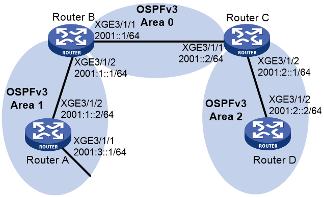
Procedure
1. Configure IPv6 addresses for interfaces. (Details not shown.)
2. Configure basic OSPFv3 (see "Example: Configuring OSPFv3 stub area").
3. Configure Area 1 as an NSSA area:
# Configure Router A.
<RouterA> system-view
[RouterA] ospfv3
[RouterA-ospfv3-1] area 1
[RouterA-ospfv3-1-area-0.0.0.1] nssa
[RouterA-ospfv3-1-area-0.0.0.1] quit
[RouterA-ospfv3-1] quit
# Configure Router B.
<RouterB> system-view
[RouterB] ospfv3
[RouterB-ospfv3-1] area 1
[RouterB-ospfv3-1-area-0.0.0.1] nssa
[RouterB-ospfv3-1-area-0.0.0.1] quit
[RouterB-ospfv3-1] quit
# Display OSPFv3 routing information on Router D.
[RouterD] display ospfv3 1 routing
OSPFv3 Process 1 with Router ID 4.4.4.4
-------------------------------------------------------------------------
I - Intra area route, E1 - Type 1 external route, N1 - Type 1 NSSA route
IA - Inter area route, E2 - Type 2 external route, N2 - Type 2 NSSA route
* - Selected route
*Destination: 2001::/64
Type : IA Area : 0.0.0.2
AdvRouter : 3.3.3.3 Preference : 10
NibID : 0x23000003 Cost : 2
Interface : XGE3/1/2 BkInterface: N/A
Nexthop : FE80::48C0:26FF:FEDA:305
BkNexthop : N/A
Status : Rely
*Destination: 2001:1::/64
Type : IA Area : 0.0.0.2
AdvRouter : 3.3.3.3 Preference : 10
NibID : 0x23000003 Cost : 3
Interface : XGE3/1/2 BkInterface: N/A
Nexthop : FE80::48C0:26FF:FEDA:305
BkNexthop : N/A
Status : Rely
*Destination: 2001:2::/64
Type : I Area : 0.0.0.2
AdvRouter : 4.4.4.4 Preference : 10
NibID : 0x23000001 Cost : 1
Interface : XGE3/1/2 BkInterface: N/A
Nexthop : ::
BkNexthop : N/A
Status : Direct
*Destination: 2001:3::/64
Type : IA Area : 0.0.0.2
AdvRouter : 3.3.3.3 Preference : 10
NibID : 0x23000003 Cost : 4
Interface : XGE3/1/2 BkInterface: N/A
Nexthop : FE80::48C0:26FF:FEDA:305
BkNexthop : N/A
Status : Rely
Total: 4
Intra area: 1 Inter area: 3 ASE: 0 NSSA: 0
4. Configure route redistribution:
# Configure an IPv6 static route, and configure OSPFv3 to redistribute the static route on Router A.
[RouterA] ipv6 route-static 1234:: 64 null 0
[RouterA] ospfv3 1
[RouterA-ospfv3-1] import-route static
[RouterA-ospfv3-1] quit
# Display OSPFv3 routing information on Router D.
[RouterD] display ospfv3 1 routing
OSPFv3 Process 1 with Router ID 4.4.4.4
-------------------------------------------------------------------------
I - Intra area route, E1 - Type 1 external route, N1 - Type 1 NSSA route
IA - Inter area route, E2 - Type 2 external route, N2 - Type 2 NSSA route
* - Selected route
*Destination: 2001::/64
Type : IA Area : 0.0.0.2
AdvRouter : 3.3.3.3 Preference : 10
NibID : 0x23000002 Cost : 2
Interface : XGE3/1/2 BkInterface: N/A
Nexthop : FE80::48C0:26FF:FEDA:305
BkNexthop : N/A
Status : Rely
*Destination: 2001:1::/64
Type : IA Area : 0.0.0.2
AdvRouter : 3.3.3.3 Preference : 10
NibID : 0x23000002 Cost : 3
Interface : XGE3/1/2 BkInterface: N/A
Nexthop : FE80::48C0:26FF:FEDA:305
BkNexthop : N/A
Status : Rely
*Destination: 2001:2::/64
Type : I Area : 0.0.0.2
AdvRouter : 4.4.4.4 Preference : 10
NibID : 0x23000004 Cost : 1
Interface : XGE3/1/2 BkInterface: N/A
Nexthop : ::
BkNexthop : N/A
Status : Direct
*Destination: 2001:3::/64
Type : IA Area : 0.0.0.2
AdvRouter : 3.3.3.3 Preference : 10
NibID : 0x23000002 Cost : 4
Interface : XGE3/1/2 BkInterface: N/A
Nexthop : FE80::48C0:26FF:FEDA:305
BkNexthop : N/A
Status : Rely
*Destination: 1234::/64
Type : E2 Tag : 1
AdvRouter : 2.2.2.2 Preference : 150
NibID : 0x23000001 Cost : 1
Interface : XGE3/1/2 BkInterface: N/A
Nexthop : FE80::48C0:26FF:FEDA:305
BkNexthop : N/A
Status : Normal
Total: 5
Intra area: 1 Inter area: 3 ASE: 1 NSSA: 0
The output shows an AS external route imported from the NSSA area exists on Router D.
Example: Configuring OSPFv3 DR election
Network configuration
As shown in Figure 12:
· Configure router priority 100 for Router A, the highest priority on the network, so it will become the DR.
· Configure router priority 2 for Router C, the second highest priority on the network, so it will become the BDR.
· Configure router priority 0 for Router B, so it cannot become a DR or BDR.
· Router D uses the default router priority 1.
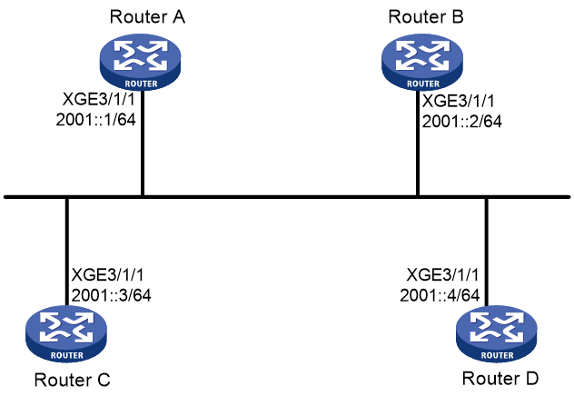
Procedure
1. Configure IPv6 addresses for interfaces. (Details not shown.)
2. Configure basic OSPFv3:
# On Router A, enable OSPFv3, and specify the router ID as 1.1.1.1.
<RouterA> system-view
[RouterA] ospfv3
[RouterA-ospfv3-1] router-id 1.1.1.1
[RouterA-ospfv3-1] quit
[RouterA] interface ten-gigabitethernet 3/1/1
[RouterA-Ten-GigabitEthernet3/1/1] ospfv3 1 area 0
[RouterA-Ten-GigabitEthernet3/1/1] quit
# On Router B, enable OSPFv3, and specify the router ID as 2.2.2.2.
<RouterB> system-view
[RouterB] ospfv3
[RouterB-ospfv3-1] router-id 2.2.2.2
[RouterB-ospfv3-1] quit
[RouterB] interface ten-gigabitethernet 3/1/1
[RouterB-Ten-GigabitEthernet3/1/1] ospfv3 1 area 0
[RouterB-Ten-GigabitEthernet3/1/1] quit
# On Router C, enable OSPFv3, and specify the router ID as 3.3.3.3.
<RouterC> system-view
[RouterC] ospfv3
[RouterC-ospfv3-1] router-id 3.3.3.3
[RouterC-ospfv3-1] quit
[RouterC] interface ten-gigabitethernet 3/1/1
[RouterC-Ten-GigabitEthernet3/1/1] ospfv3 1 area 0
[RouterC-Ten-GigabitEthernet3/1/1] quit
# On Router D, enable OSPFv3, and specify the router ID as 4.4.4.4.
<RouterD> system-view
[RouterD] ospfv3
[RouterD-ospfv3-1] router-id 4.4.4.4
[RouterD-ospfv3-1] quit
[RouterD] interface ten-gigabitethernet 3/1/1
[RouterD-Ten-GigabitEthernet3/1/1] ospfv3 1 area 0
[RouterD-Ten-GigabitEthernet3/1/1] quit
# Display neighbors on Router A. The routers have the same default router priority 1, so Router D (the router with the highest router ID) is elected as the DR, and Router C is the BDR.
[RouterA] display ospfv3 peer
OSPFv3 Process 1 with Router ID 1.1.1.1
Area: 0.0.0.0
-------------------------------------------------------------------------
Router ID Pri State Dead-Time InstID Interface
2.2.2.2 1 2-Way/DROther 00:00:36 0 XGE3/1/1
3.3.3.3 1 Full/BDR 00:00:35 0 XGE3/1/1
4.4.4.4 1 Full/DR 00:00:33 0 XGE3/1/1
# Display neighbors on Router D. The neighbor states are all full.
[RouterD] display ospfv3 peer
OSPFv3 Process 1 with Router ID 4.4.4.4
Area: 0.0.0.0
-------------------------------------------------------------------------
Router ID Pri State Dead-Time InstID Interface
1.1.1.1 1 Full/DROther 00:00:30 0 XGE3/1/1
2.2.2.2 1 Full/DROther 00:00:37 0 XGE3/1/1
3.3.3.3 1 Full/BDR 00:00:31 0 XGE3/1/1
3. Configure router priorities for interfaces:
# Set the router priority to 100 for the interface Ten-GigabitEthernet 3/1/1 of Router A.
[RouterA] interface ten-gigabitethernet 3/1/1
[RouterA-Ten-GigabitEthernet3/1/1] ospfv3 dr-priority 100
[RouterA-Ten-GigabitEthernet3/1/1] quit
# Set the router priority to 0 for the interface Ten-GigabitEthernet 3/1/1 of Router B.
[RouterB] interface ten-gigabitethernet 3/1/1
[RouterB-Ten-GigabitEthernet3/1/1] ospfv3 dr-priority 0
[RouterB-Ten-GigabitEthernet3/1/1] quit
# Set the router priority to 2 for the interface Ten-GigabitEthernet 3/1/1 of Router C.
[RouterC] interface ten-gigabitethernet 3/1/1
[RouterC-Ten-GigabitEthernet3/1/1] ospfv3 dr-priority 2
[RouterC-Ten-GigabitEthernet3/1/1] quit
# Display neighbors on Router A. The output shows that the router priorities have been changed, but the DR and BDR are not changed.
[RouterA] display ospfv3 peer
OSPFv3 Process 1 with Router ID 1.1.1.1
Area: 0.0.0.0
-------------------------------------------------------------------------
Router ID Pri State Dead-Time InstID Interface
2.2.2.2 0 2-Way/DROther 00:00:36 0 XGE3/1/1
3.3.3.3 2 Full/BDR 00:00:35 0 XGE3/1/1
4.4.4.4 1 Full/DR 00:00:33 0 XGE3/1/1
# Display neighbors on Router D.
[RouterD] display ospfv3 peer
OSPFv3 Process 1 with Router ID 4.4.4.4
Area: 0.0.0.0
-------------------------------------------------------------------------
Router ID Pri State Dead-Time InstID Interface
1.1.1.1 100 Full/DROther 00:00:30 0 XGE3/1/1
2.2.2.2 0 Full/DROther 00:00:37 0 XGE3/1/1
3.3.3.3 2 Full/BDR 00:00:31 0 XGE3/1/1
The output shows that the DR is still Router D.
4. Enable DR/BDR election:
# Perform the shutdown and undo shutdown commands on each interface to enable a new DR/BD election. (Details not shown.)
# Display neighbors on Router A. The output shows that Router C becomes the BDR.
[RouterA] display ospfv3 peer
OSPFv3 Process 1 with Router ID 1.1.1.1
Area: 0.0.0.0
-------------------------------------------------------------------------
Router ID Pri State Dead-Time InstID Interface
2.2.2.2 0 Full/DROther 00:00:36 0 XGE3/1/1
3.3.3.3 2 Full/BDR 00:00:35 0 XGE3/1/1
4.4.4.4 1 Full/DROther 00:00:33 0 XGE3/1/1
# Display neighbors on Router D.
[RouterD] display ospfv3 peer
OSPFv3 Process 1 with Router ID 4.4.4.4
Area: 0.0.0.0
-------------------------------------------------------------------------
Router ID Pri State Dead-Time InstID Interface
1.1.1.1 100 Full/DR 00:00:30 0 XGE3/1/1
2.2.2.2 0 2-Way/DROther 00:00:37 0 XGE3/1/1
3.3.3.3 2 Full/BDR 00:00:31 0 XGE3/1/1
The output shows that Router A becomes the DR.
Example: Configuring OSPFv3 route redistribution
Network configuration
As shown in Figure 13:
· Router A, Router B, and Router C are in Area 2.
· OSPFv3 process 1 and OSPFv3 process 2 run on Router B. Router B communicates with Router A and Router C through OSPFv3 process 1 and OSPFv3 process 2.
· Configure OSPFv3 process 2 to redistribute direct routes and the routes from OSPFv3 process 1 on Router B, and set the metric for redistributed routes to 3. Router C can then learn the routes destined for 1::0/64 and 2::0/64, and Router A cannot learn the routes destined for 3::0/64 or 4::0/64.
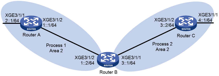
Procedure
1. Configure IPv6 addresses for interfaces. (Details not shown.)
2. Configure basic OSPFv3:
# Enable OSPFv3 process 1 on Router A.
<RouterA> system-view
[RouterA] ospfv3 1
[RouterA-ospfv3-1] router-id 1.1.1.1
[RouterA-ospfv3-1] quit
[RouterA] interface ten-gigabitethernet 3/1/2
[RouterA-Ten-GigabitEthernet3/1/2] ospfv3 1 area 2
[RouterA-Ten-GigabitEthernet3/1/2] quit
[RouterA] interface ten-gigabitethernet 3/1/1
[RouterA-Ten-GigabitEthernet3/1/1] ospfv3 1 area 2
[RouterA-Ten-GigabitEthernet3/1/1] quit
# Enable OSPFv3 process 1 and OSPFv3 process 2 on Router B.
<RouterB> system-view
[RouterB] ospfv3 1
[RouterB-ospfv3-1] router-id 2.2.2.2
[RouterB-ospfv3-1] quit
[RouterB] interface ten-gigabitethernet 3/1/2
[RouterB-Ten-GigabitEthernet3/1/2] ospfv3 1 area 2
[RouterB-Ten-GigabitEthernet3/1/2] quit
[RouterB] ospfv3 2
[RouterB-ospfv3-2] router-id 3.3.3.3
[RouterB-ospfv3-2] quit
[RouterB] interface ten-gigabitethernet 3/1/1
[RouterB-Ten-GigabitEthernet3/1/1] ospfv3 2 area 2
[RouterB-Ten-GigabitEthernet3/1/1] quit
# Enable OSPFv3 process 2 on Router C.
<RouterC> system-view
[RouterC] ospfv3 2
[RouterC-ospfv3-2] router-id 4.4.4.4
[RouterC-ospfv3-2] quit
[RouterC] interface ten-gigabitethernet 3/1/2
[RouterC-Ten-GigabitEthernet3/1/2] ospfv3 2 area 2
[RouterC-Ten-GigabitEthernet3/1/2] quit
[RouterC] interface ten-gigabitethernet 3/1/1
[RouterC-Ten-GigabitEthernet3/1/1] ospfv3 2 area 2
[RouterC-Ten-GigabitEthernet3/1/1] quit
# Display the routing table on Router C.
[RouterC] display ipv6 routing-table
Destinations : 6 Routes : 6
Destination: ::1/128 Protocol : Direct
NextHop : ::1 Preference: 0
Interface : InLoop0 Cost : 0
Destination: 3::/64 Protocol : Direct
NextHop : :: Preference: 0
Interface : XGE3/1/2 Cost : 0
Destination: 3::2/128 Protocol : Direct
NextHop : ::1 Preference: 0
Interface : InLoop0 Cost : 0
Destination: 4::/64 Protocol : Direct
NextHop : :: Preference: 0
Interface : XGE3/1/1 Cost : 0
Destination: 4::1/128 Protocol : Direct
NextHop : ::1 Preference: 0
Interface : InLoop0 Cost : 0
Destination: FE80::/10 Protocol : Direct
NextHop : :: Preference: 0
Interface : NULL0 Cost : 0
3. Configure OSPFv3 route redistribution:
# Configure OSPFv3 process 2 to redistribute direct routes and the routes from OSPFv3 process 1 on Router B, and set the metric for redistributed routes to 3.
[RouterB] ospfv3 2
[RouterB-ospfv3-2] import-route ospfv3 1 cost 3
[RouterB-ospfv3-2] import-route direct cost 3
[RouterB-ospfv3-2] quit
# Display the routing table on Router C.
[RouterC] display ipv6 routing-table
Destinations : 8 Routes : 8
Destination: ::1/128 Protocol : Direct
NextHop : ::1 Preference: 0
Interface : InLoop0 Cost : 0
Destination: 1::/64 Protocol : O_ASE2
NextHop : FE80::200:CFF:FE01:1C03 Preference: 150
Interface : XGE3/1/2 Cost : 3
Destination: 2::/64 Protocol : O_ASE2
NextHop : FE80::200:CFF:FE01:1C03 Preference: 150
Interface : XGE3/1/2 Cost : 3
Destination: 3::/64 Protocol : Direct
NextHop : :: Preference: 0
Interface : XGE3/1/2 Cost : 0
Destination: 3::2/128 Protocol : Direct
NextHop : ::1 Preference: 0
Interface : InLoop0 Cost : 0
Destination: 4::/64 Protocol : Direct
NextHop : :: Preference: 0
Interface : XGE3/1/1 Cost : 0
Destination: 4::1/128 Protocol : Direct
NextHop : ::1 Preference: 0
Interface : InLoop0 Cost : 0
Destination: FE80::/10 Protocol : Direct
NextHop : :: Preference: 0
Interface : NULL0 Cost : 0
Example: Configuring OSPFv3 route summarization
Network configuration
As shown in Figure 14:
· Router A, Router B, and Router C are in Area 2.
· OSPFv3 process 1 and OSPFv3 process 2 run on Router B. Router B communicates with Router A and Router C through OSPFv3 process 1 and OSPFv3 process 2, respectively.
· On Router A, configure IPv6 addresses 2:1:1::1/64, 2:1:2::1/64, and 2:1:3::1/64 for Ten-GigabitEthernet 3/1/1.
· On Router B, configure OSPFv3 process 2 to redistribute direct routes and the routes from OSPFv3 process 1. Router C can then learn the routes destined for 2::/64, 2:1:1::/64, 2:1:2::/64, and 2:1:3::/64.
· On Router B, configure route summarization to advertise only summary route 2::/16 to Router C.

Procedure
1. Configure IPv6 addresses for interfaces. (Details not shown.)
2. Configure OSPFv3:
# Enable OSPFv3 process 1 on Router A.
<RouterA> system-view
[RouterA] ospfv3 1
[RouterA-ospfv3-1] router-id 1.1.1.1
[RouterA-ospfv3-1] quit
[RouterA] interface ten-gigabitethernet 3/1/2
[RouterA-Ten-GigabitEthernet3/1/2] ospfv3 1 area 2
[RouterA-Ten-GigabitEthernet3/1/2] quit
[RouterA] interface ten-gigabitethernet 3/1/1
[RouterA-Ten-GigabitEthernet3/1/1] ipv6 address 2:1:1::1 64
[RouterA-Ten-GigabitEthernet3/1/1] ipv6 address 2:1:2::1 64
[RouterA-Ten-GigabitEthernet3/1/1] ipv6 address 2:1:3::1 64
[RouterA-Ten-GigabitEthernet3/1/1] ospfv3 1 area 2
[RouterA-Ten-GigabitEthernet3/1/1] quit
# Enable OSPFv3 process 1 and OSPFv3 process 2 on Router B.
<RouterB> system-view
[RouterB] ospfv3 1
[RouterB-ospfv3-1] router-id 2.2.2.2
[RouterB-ospfv3-1] quit
[RouterB] interface ten-gigabitethernet 3/1/2
[RouterB-Ten-GigabitEthernet3/1/2] ospfv3 1 area 2
[RouterB-Ten-GigabitEthernet3/1/2] quit
[RouterB] ospfv3 2
[RouterB-ospfv3-2] router-id 3.3.3.3
[RouterB-ospfv3-2] quit
[RouterB] interface ten-gigabitethernet 3/1/1
[RouterB-Ten-GigabitEthernet3/1/1] ospfv3 2 area 2
[RouterB-Ten-GigabitEthernet3/1/1] quit
# Enable OSPFv3 process 2 on Router C.
<RouterC> system-view
[RouterC] ospfv3 2
[RouterC-ospfv3-2] router-id 4.4.4.4
[RouterC-ospfv3-2] quit
[RouterC] interface ten-gigabitethernet 3/1/2
[RouterC-Ten-GigabitEthernet3/1/2] ospfv3 2 area 2
[RouterC-Ten-GigabitEthernet3/1/2] quit
[RouterC] interface ten-gigabitethernet 3/1/1
[RouterC-Ten-GigabitEthernet3/1/1] ospfv3 2 area 2
[RouterC-Ten-GigabitEthernet3/1/1] quit
3. Configure OSPFv3 route redistribution:
# Configure OSPFv3 process 2 to redistribute direct routes and the routes from OSPFv3 process 1 on Router B.
[RouterB] ospfv3 2
[RouterB-ospfv3-2] import-route ospfv3 1
[RouterB-ospfv3-2] import-route direct
[RouterB-ospfv3-2] quit
# Display the routing table on Router C.
[RouterC] display ipv6 routing-table
Destinations : 11 Routes : 11
Destination: ::1/128 Protocol : Direct
NextHop : ::1 Preference: 0
Interface : InLoop0 Cost : 0
Destination: 1::/64 Protocol : O_ASE2
NextHop : FE80::200:CFF:FE01:1C03 Preference: 150
Interface : XGE3/1/2 Cost : 1
Destination: 2::/64 Protocol : O_ASE2
NextHop : FE80::200:CFF:FE01:1C03 Preference: 150
Interface : XGE3/1/2 Cost : 1
Destination: 2:1:1::/64 Protocol : O_ASE2
NextHop : FE80::200:CFF:FE01:1C03 Preference: 150
Interface : XGE3/1/2 Cost : 1
Destination: 2:1:2::/64 Protocol : O_ASE2
NextHop : FE80::200:CFF:FE01:1C03 Preference: 150
Interface : XGE3/1/2 Cost : 1
Destination: 2:1:3::/64 Protocol : O_ASE2
NextHop : FE80::200:CFF:FE01:1C03 Preference: 150
Interface : XGE3/1/2 Cost : 1
Destination: 3::/64 Protocol : Direct
NextHop : 3::2 Preference: 0
Interface : XGE3/1/2 Cost : 0
Destination: 3::2/128 Protocol : Direct
NextHop : ::1 Preference: 0
Interface : InLoop0 Cost : 0
Destination: 4::/64 Protocol : Direct
NextHop : 4::1 Preference: 0
Interface : XGE3/1/1 Cost : 0
Destination: 4::1/128 Protocol : Direct
NextHop : ::1 Preference: 0
Interface : InLoop0 Cost : 0
Destination: FE80::/10 Protocol : Direct
NextHop : :: Preference: 0
Interface : NULL0 Cost : 0
4. Configure ASBR route summarization:
# On Router B, configure OSPFv3 process 2 to advertise a summary route 2::/16.
[RouterB] ospfv3 2
[RouterB-ospfv3-2] asbr-summary 2:: 16
[RouterB-ospfv3-2] quit
# Display the routing table on Router C.
[RouterC] display ipv6 routing-table
Destinations : 8 Routes : 8
Destination: ::1/128 Protocol : Direct
NextHop : ::1 Preference: 0
Interface : InLoop0 Cost : 0
Destination: 1::/64 Protocol : O_ASE2
NextHop : FE80::200:CFF:FE01:1C03 Preference: 150
Interface : XGE3/1/2 Cost : 1
Destination: 2::/16 Protocol : O_ASE2
NextHop : FE80::200:CFF:FE01:1C03 Preference: 150
Interface : XGE3/1/2 Cost : 1
Destination: 3::/64 Protocol : Direct
NextHop : 3::2 Preference: 0
Interface : XGE3/1/2 Cost : 0
Destination: 3::2/128 Protocol : Direct
NextHop : ::1 Preference: 0
Interface : InLoop0 Cost : 0
Destination: 4::/64 Protocol : Direct
NextHop : 4::1 Preference: 0
Interface : XGE3/1/1 Cost : 0
Destination: 4::1/128 Protocol : Direct
NextHop : ::1 Preference: 0
Interface : InLoop0 Cost : 0
Destination: FE80::/10 Protocol : Direct
NextHop : :: Preference: 0
Interface : NULL0 Cost : 0
Example: Configuring OSPFv3 GR
Network configuration
As shown in Figure 15:
· Router A, Router B, and Router C that reside in the same AS and the same OSPFv3 routing domain are GR capable.
· Router A acts as the GR restarter. Router B and Router C act as GR helpers, and synchronize their LSDBs with Router A through GR.
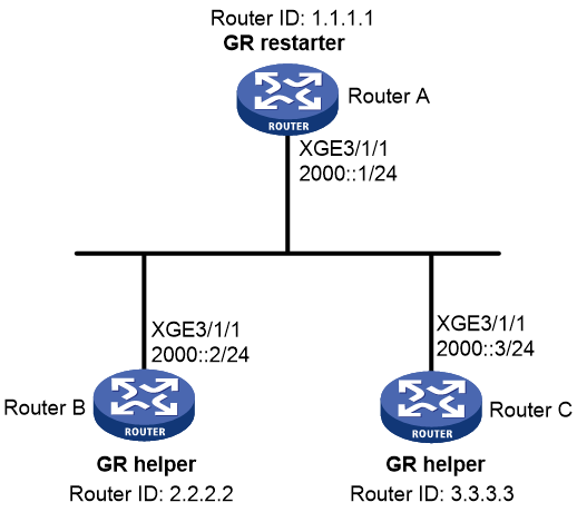
Procedure
1. Configure IPv6 addresses for interfaces. (Details not shown.)
2. Configure basic OSPFv3:
# On Router A, enable OSPFv3 process 1, enable GR, and set the router ID to 1.1.1.1.
<RouterA> system-view
[RouterA] ospfv3 1
[RouterA-ospfv3-1] router-id 1.1.1.1
[RouterA-ospfv3-1] graceful-restart enable
[RouterA-ospfv3-1] quit
[RouterA] interface ten-gigabitethernet 3/1/1
[RouterA-Ten-GigabitEthernet3/1/1] ospfv3 1 area 1
[RouterA-Ten-GigabitEthernet3/1/1] quit
# On Router B, enable OSPFv3 and set the router ID to 2.2.2.2. (By default, GR helper is enabled on a router.)
<RouterB> system-view
[RouterB] ospfv3 1
[RouterB-ospfv3-1] router-id 2.2.2.2
[RouterB-ospfv3-1] quit
[RouterB] interface ten-gigabitethernet 3/1/1
[RouterB-Ten-GigabitEthernet3/1/1] ospfv3 1 area 1
[RouterB-Ten-GigabitEthernet3/1/1] quit
# On Router C, enable OSPFv3 and set the router ID to 3.3.3.3. (By default, GR helper is enabled on a router.)
<RouterC> system-view
[RouterC] ospfv3 1
[RouterC-ospfv3-1] router-id 3.3.3.3
[RouterC-ospfv3-1] quit
[RouterC] interface ten-gigabitethernet 3/1/1
[RouterC-Ten-GigabitEthernet3/1/1] ospfv3 1 area 1
[RouterC-Ten-GigabitEthernet3/1/1] quit
Verifying the configuration
# Perform an active/standby switchover on Router A to trigger an OSPFv3 GR operation. (Details not shown.)
Example: Configuring BFD for OSPFv3
Network configuration
As shown in Figure 16:
· Configure OSPFv3 on Router A, Router B and Router C and configure BFD over the link Router A<—>L2 Switch<—>Router B.
· After the link Router A<—>L2 Switch<—>Router B fails, BFD can quickly detect the failure and notify OSPFv3 of the failure. Then Router A and Router B communicate through Router C.
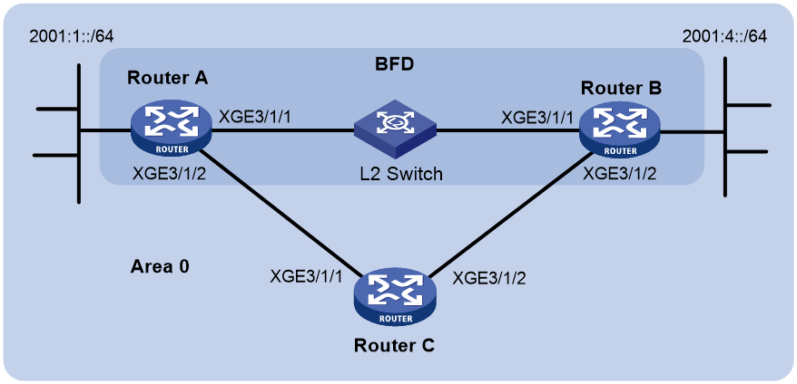
Table 1 Interface and IP address assignment
|
Device |
Interface |
IPv6 address |
|
Router A |
XGE3/1/1 |
2001::1/64 |
|
Router A |
XGE3/1/2 |
2001:2::1/64 |
|
Router B |
XGE3/1/1 |
2001::2/64 |
|
Router B |
XGE3/1/2 |
2001:3::2/64 |
|
Router C |
XGE3/1/1 |
2001:2::2/64 |
|
Router C |
XGE3/1/2 |
2001:3::1/64 |
Procedure
1. Configure IPv6 addresses for interfaces. (Details not shown.)
2. Configure basic OSPFv3:
# Enable OSPFv3 and set the router ID to 1.1.1.1 on Router A.
<RouterA> system-view
[RouterA] ospfv3 1
[RouterA-ospfv3-1] router-id 1.1.1.1
[RouterA-ospfv3-1] quit
[RouterA] interface ten-gigabitethernet 3/1/1
[RouterA-Ten-GigabitEthernet3/1/1] ospfv3 1 area 0
[RouterA-Ten-GigabitEthernet3/1/1] quit
[RouterA] interface ten-gigabitethernet 3/1/2
[RouterA-Ten-GigabitEthernet3/1/2] ospfv3 1 area 0
[RouterA-Ten-GigabitEthernet3/1/2] quit
# Enable OSPFv3 and set the router ID to 2.2.2.2 on Router B.
<RouterB> system-view
[RouterB] ospfv3 1
[RouterB-ospfv3-1] router-id 2.2.2.2
[RouterB-ospfv3-1] quit
[RouterB] interface ten-gigabitethernet 3/1/1
[RouterB-Ten-GigabitEthernet3/1/1] ospfv3 1 area 0
[RouterB-Ten-GigabitEthernet3/1/1] quit
[RouterB] interface ten-gigabitethernet 3/1/2
[RouterB-Ten-GigabitEthernet3/1/2] ospfv3 1 area 0
[RouterB-Ten-GigabitEthernet3/1/2] quit
# Enable OSPFv3 and set the router ID to 3.3.3.3 on Router C.
<RouterC> system-view
[RouterC] ospfv3 1
[RouterC-ospfv3-1] router-id 3.3.3.3
[RouterC-ospfv3-1] quit
[RouterC] interface ten-gigabitethernet 3/1/1
[RouterC-Ten-GigabitEthernet3/1/1] ospfv3 1 area 0
[RouterC-Ten-GigabitEthernet3/1/1] quit
[RouterC] interface ten-gigabitethernet 3/1/2
[RouterC-Ten-GigabitEthernet3/1/2] ospfv3 1 area 0
[RouterC-Ten-GigabitEthernet3/1/2] quit
3. Configure BFD:
# Enable BFD and configure BFD parameters on Router A.
[RouterA] bfd session init-mode active
[RouterA] interface ten-gigabitethernet 3/1/1
[RouterA-Ten-GigabitEthernet3/1/1] ospfv3 bfd enable
[RouterA-Ten-GigabitEthernet3/1/1] bfd min-transmit-interval 500
[RouterA-Ten-GigabitEthernet3/1/1] bfd min-receive-interval 500
[RouterA-Ten-GigabitEthernet3/1/1] bfd detect-multiplier 7
[RouterA-Ten-GigabitEthernet3/1/1] quit
# Enable BFD and configure BFD parameters on Router B.
[RouterB] bfd session init-mode active
[RouterB] interface ten-gigabitethernet 3/1/1
[RouterB-Ten-GigabitEthernet3/1/1] ospfv3 bfd enable
[RouterB-Ten-GigabitEthernet3/1/1] bfd min-transmit-interval 500
[RouterB-Ten-GigabitEthernet3/1/1] bfd min-receive-interval 500
[RouterB-Ten-GigabitEthernet3/1/1] bfd detect-multiplier 6
[RouterB-Ten-GigabitEthernet3/1/1] quit
Verifying the configuration
# Display the BFD information on Router A.
[RouterA] display bfd session
Total sessions: 1 Up sessions: 1 Init mode: Active
IPv6 session working in control packet mode:
Local discr: 1441 Remote discr: 1450
Source IP: FE80::20F:FF:FE00:1202 (link-local address of Ten-GigabitEthernet3/1/1 on Router A)
Destination IP: FE80::20F:FF:FE00:1200 (link-local address of Ten-GigabitEthernet3/1/1 on Router B)
Session state: Up Interface: XGE3/1/1
Hold time: 2319ms
# Display routes destined for 2001:4::0/64 on Router A.
[RouterA] display ipv6 routing-table 2001:4::0 64
Summary Count : 1
Destination: 2001:4::/64 Protocol : O_INTRA
NextHop : FE80::20F:FF:FE00:1200 Preference: 10
Interface : XGE3/1/1 Cost : 1
The output shows that Router A communicates with Router B through Ten-GigabitEthernet 3/1/1. Then the link over Ten-GigabitEthernet 3/1/1 fails.
# Display routes destined for 2001:4::0/64 on Router A.
[RouterA] display ipv6 routing-table 2001:4::0 64
Summary Count : 1
Destination: 2001:4::/64 Protocol : O_INTRA
NextHop : FE80::BAAF:67FF:FE27:DCD0 Preference: 10
Interface : XGE3/1/2 Cost : 2
The output shows that Router A communicates with Router B through Ten-GigabitEthernet 3/1/2.
Example: Configuring OSPFv3 FRR
Network configuration
As shown in Figure 17, Router A, Router B, and Router C reside in the same OSPFv3 domain. Configure OSPFv3 FRR so that when Link A fails, traffic is immediately switched to Link B.
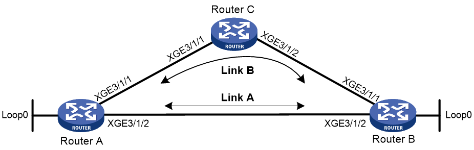
Table 2 Interface and IP address assignment
|
Device |
Interface |
IP address |
Device |
Interface |
IP address |
|
Router A |
XGE3/1/1 |
1::1/64 |
Router B |
XGE3/1/1 |
3::1/64 |
|
|
XGE3/1/2 |
2::1/64 |
|
XGE3/1/2 |
2::2/64 |
|
|
Loop0 |
10::1/128 |
|
Loop0 |
20::1/128 |
|
Router C |
XGE3/1/1 |
1::2/64 |
|
|
|
|
|
XGE3/1/2 |
3::2/64 |
|
|
|
Procedure
1. Configure IPv6 addresses for interfaces on the routers. (Details not shown.)
2. Configure OSPFv3 on the routers to ensure that Router A, Router B, and Router C can communicate with each other at the network layer. (Details not shown.)
3. Configure OSPFv3 FRR:
You can enable OSPFv3 FRR to either calculate a backup next hop by using the LFA algorithm, or specify a backup next hop by using a routing policy.
¡ (Method 1.) Enable OSPFv3 FRR to calculate a backup next hop by using the LFA algorithm:
# Configure Router A.
<RouterA> system-view
[RouterA] ospfv3 1
[RouterA-ospfv3-1] fast-reroute lfa
[RouterA-ospfv3-1] quit
# Configure Router B.
<RouterB> system-view
[RouterB] ospfv3 1
[RouterB-ospfv3-1] fast-reroute lfa
[RouterB-ospfv3-1] quit
¡ (Method 2.) Enable OSPFv3 FRR to specify a backup next hop by using a routing policy:
# Configure Router A.
<RouterA> system-view
[RouterA] ipv6 prefix-list abc index 10 permit 20::1 128
[RouterA] route-policy frr permit node 10
[RouterA-route-policy-frr-10] if-match ipv6 address prefix-list abc
[RouterA-route-policy-frr-10] apply ipv6 fast-reroute backup-interface ten-gigabitethernet 3/1/1 backup-nexthop 1::2
[RouterA-route-policy-frr-10] quit
[RouterA] ospfv3 1
[RouterA-ospfv3-1] fast-reroute route-policy frr
[RouterA-ospfv3-1] quit
# Configure Router B.
<RouterB> system-view
[RouterB] ipv6 prefix-list abc index 10 permit 10::1 128
[RouterB] route-policy frr permit node 10
[RouterB-route-policy-frr-10] if-match ipv6 address prefix-list abc
[RouterB-route-policy-frr-10] apply ipv6 fast-reroute backup-interface ten-gigabitethernet 3/1/1 backup-nexthop 3::2
[RouterB-route-policy-frr-10] quit
[RouterB] ospfv3 1
[RouterB-ospfv3-1] fast-reroute route-policy frr
[RouterB-ospfv3-1] quit
Verifying the configuration
# Display the route 20::1/128 on Router A to view the backup next hop information.
[RouterA] display ipv6 routing-table 20::1 128 verbose
Summary count : 1
Destination: 20::1/128
Protocol: O_INTRA
Process ID: 1
SubProtID: 0x1 Age: 00h03m45s
FlushedAge: 15h28m49s
Cost: 6 Preference: 10
IpPre: N/A QosLocalID: N/A
Tag: 0 State: Active Adv
OrigTblID: 0x0 OrigVrf: default-vrf
TableID: 0xa OrigAs: 0
NibID: 0x23000005 LastAs: 0
AttrID: 0xffffffff
BkAttrID: 0xffffffff Neighbor: ::
Flags: 0x10041 OrigNextHop: FE80::7685:45FF:FEAD:102
Label: NULL RealNextHop: FE80::7685:45FF:FEAD:102
BkLabel: NULL BkNextHop: FE80::34CD:9FF:FE2F:D02
SRLabel: NULL Interface: Ten-GigabitEthernet3/1/2
BkSRLabel: NULL BkInterface: N/A
Tunnel ID: Invalid IPInterface: Ten-GigabitEthernet3/1/2
BkTunnel ID: Invalid BkIPInterface: Ten-GigabitEthernet3/1/1
InLabel: NULL ColorInterface: N/A
SIDIndex: NULL BkColorInterface: N/A
FtnIndex: 0x0 TunnelInterface: N/A
TrafficIndex: N/A BkTunnelInterface: N/A
Connector: N/A PathID: 0x0
UserID: 0x0 SRTunnelID: Invalid
SID Type: N/A NID: Invalid
FlushNID: Invalid BkNID: Invalid
BkFlushNID: Invalid StatFlags: 0x0
SID: N/A
BkSID: N/A
CommBlockLen: 0 Priority: Critical
MemberPort: N/A
# Display the route 10::1/128 on Router B to view the backup next hop information.
[RouterB] display ipv6 routing-table 10::1 128 verbose
Summary count : 1
Destination: 10::1/128
Protocol: O_INTRA
Process ID: 1
SubProtID: 0x1 Age: 00h03m10s
FlushedAge: 15h28m49s
Cost: 1 Preference: 10
IpPre: N/A QosLocalID: N/A
Tag: 0 State: Active Adv
OrigTblID: 0x0 OrigVrf: default-vrf
TableID: 0xa OrigAs: 0
NibID: 0x23000006 LastAs: 0
AttrID: 0xffffffff
BkAttrID: 0xffffffff Neighbor: ::
Flags: 0x10041 OrigNextHop: FE80::34CC:E8FF:FE5B:C02
Label: NULL RealNextHop: FE80::34CC:E8FF:FE5B:C02
BkLabel: NULL BkNextHop: FE80::7685:45FF:FEAD:102
SRLabel: NULL Interface: Ten-GigabitEthernet3/1/2
BkSRLabel: NULL BkInterface: N/A
Tunnel ID: Invalid IPInterface: Ten-GigabitEthernet3/1/2
BkTunnel ID: Invalid BkIPInterface: Ten-GigabitEthernet3/1/1
InLabel: NULL ColorInterface: N/A
SIDIndex: NULL BkColorInterface: N/A
FtnIndex: 0x0 TunnelInterface: N/A
TrafficIndex: N/A BkTunnelInterface: N/A
Connector: N/A PathID: 0x0
UserID: 0x0 SRTunnelID: Invalid
SID Type: N/A NID: Invalid
FlushNID: Invalid BkNID: Invalid
BkFlushNID: Invalid StatFlags: 0x0
SID: N/A
BkSID: N/A
CommBlockLen: 0 Priority: Critical
MemberPort: N/A
Example: Configuring OSPFv3 IPsec profile
Network configuration
As shown in Figure 18, all routers run OSPFv3, and the AS is divided into two areas.
Configure IPsec profiles on the routers to authenticate and encrypt protocol packets.
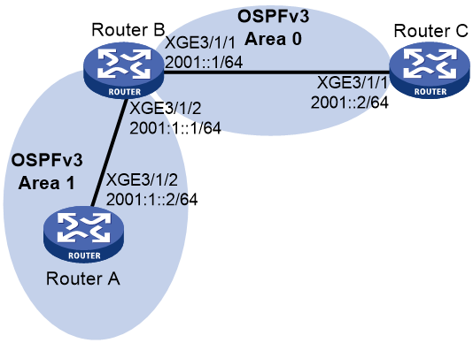
Procedure
1. Configure IPv6 addresses for interfaces. (Details not shown.)
2. Configure OSPFv3 basic features:
# On Router A, enable OSPFv3 and specify the router ID as 1.1.1.1.
<RouterA> system-view
[RouterA] ospfv3 1
[RouterA-ospfv3-1] router-id 1.1.1.1
[RouterA-ospfv3-1] quit
[RouterA] interface ten-gigabitethernet 3/1/2
[RouterA-Ten-GigabitEthernet3/1/2] ospfv3 1 area 1
[RouterA-Ten-GigabitEthernet3/1/2] quit
# On Router B, enable OSPFv3 and specify the router ID as 2.2.2.2.
<RouterB> system-view
[RouterB] ospfv3 1
[RouterB-ospfv3-1] router-id 2.2.2.2
[RouterB-ospfv3-1] quit
[RouterB] interface ten-gigabitethernet 3/1/1
[RouterB-Ten-GigabitEthernet3/1/1] ospfv3 1 area 0
[RouterB-Ten-GigabitEthernet3/1/1] quit
[RouterB] interface ten-gigabitethernet 3/1/2
[RouterB-Ten-GigabitEthernet3/1/2] ospfv3 1 area 1
[RouterB-Ten-GigabitEthernet3/1/2] quit
# On Router C, enable OSPFv3 and specify the router ID as 3.3.3.3.
<RouterC> system-view
[RouterC] ospfv3 1
[RouterC-ospfv3-1] router-id 3.3.3.3
[RouterC-ospfv3-1] quit
[RouterC] interface ten-gigabitethernet 3/1/1
[RouterC-Ten-GigabitEthernet3/1/1] ospfv3 1 area 0
[RouterC-Ten-GigabitEthernet3/1/1] quit
3. Configure OSPFv3 IPsec profiles:
¡ On Router A:
# Create an IPsec transform set named trans.
[RouterA] ipsec transform-set trans
# Specify the encapsulation mode as transport.
[RouterA-ipsec-transform-set-trans] encapsulation-mode transport
# Specify the ESP encryption and authentication algorithms.
[RouterA-ipsec-transform-set-trans] protocol esp
[RouterA-ipsec-transform-set-trans] esp encryption-algorithm aes-cbc-128
[RouterA-ipsec-transform-set-trans] esp authentication-algorithm sha1
[RouterA-ipsec-transform-set-trans] quit
# Create a manual IPsec profile named profile001.
[RouterA] ipsec profile profile001 manual
# Use IPsec transform set trans.
[RouterA-ipsec-profile-manual-profile001] transform-set trans
# Configure the inbound and outbound SPIs for ESP.
[RouterA-ipsec-profile-manual-profile001] sa spi outbound esp 123456
[RouterA-ipsec-profile-manual-profile001] sa spi inbound esp 123456
# Configure the inbound and outbound SA keys for ESP.
[RouterA-ipsec-profile-manual-profile001] sa string-key outbound esp simple abcdefg
[RouterA-ipsec-profile-manual-profile001] sa string-key inbound esp simple abcdefg
[RouterA-ipsec-profile-manual-profile001] quit
¡ On Router B:
# Create an IPsec transform set named trans.
[RouterB] ipsec transform-set trans
# Specify the encapsulation mode as transport.
[RouterB-ipsec-transform-set-trans] encapsulation-mode transport
# Specify the ESP encryption and authentication algorithms.
[RouterB-ipsec-transform-set-trans] protocol esp
[RouterB-ipsec-transform-set-trans] esp encryption-algorithm aes-cbc-128
[RouterB-ipsec-transform-set-trans] esp authentication-algorithm sha1
[RouterB-ipsec-transform-set-trans] quit
# Create a manual IPsec profile named profile001.
[RouterB] ipsec profile profile001 manual
# Use IPsec transform set trans.
[RouterB-ipsec-profile-manual-profile001] transform-set trans
# Configure the inbound and outbound SPIs for ESP.
[RouterB-ipsec-profile-manual-profile001] sa spi outbound esp 123456
[RouterB-ipsec-profile-manual-profile001] sa spi inbound esp 123456
# Configure the inbound and outbound SA keys for ESP.
[RouterB-ipsec-profile-manual-profile001] sa string-key outbound esp simple abcdefg
[RouterB-ipsec-profile-manual-profile001] sa string-key inbound esp simple abcdefg
[RouterB-ipsec-profile-manual-profile001] quit
# Create a manual IPsec profile named profile002.
[RouterB] ipsec profile profile002 manual
# Use IPsec transform set trans.
[RouterB-ipsec-profile-manual-profile002] transform-set trans
# Configure the inbound and outbound SPIs for ESP.
[RouterB-ipsec-profile-manual-profile002] sa spi outbound esp 256
[RouterB-ipsec-profile-manual-profile002] sa spi inbound esp 256
# Configure the inbound and outbound SA keys for ESP.
[RouterB-ipsec-profile-manual-profile002] sa string-key outbound esp simple byebye
[RouterB-ipsec-profile-manual-profile002] sa string-key inbound esp simple byebye
[RouterB-ipsec-profile-manual-profile002] quit
¡ On Router C:
# Create an IPsec transform set named trans.
[RouterC] ipsec transform-set trans
# Specify the encapsulation mode as transport.
[RouterC-ipsec-transform-set-trans] encapsulation-mode transport
# Specify the ESP encryption and authentication algorithms.
[RouterC-ipsec-transform-set-trans] protocol esp
[RouterC-ipsec-transform-set-trans] esp encryption-algorithm aes-cbc-128
[RouterC-ipsec-transform-set-trans] esp authentication-algorithm sha1
[RouterC-ipsec-transform-set-trans] quit
# Create a manual IPsec profile named profile002.
[RouterC] ipsec profile profile002 manual
# Use IPsec transform set trans.
[RouterC-ipsec-profile-manual-profile002] transform-set trans
# Configure the inbound and outbound SPIs for ESP.
[RouterC-ipsec-profile-manual-profile002] sa spi outbound esp 256
[RouterC-ipsec-profile-manual-profile002] sa spi inbound esp 256
# Configure the inbound and outbound SA keys for ESP.
[RouterC-ipsec-profile-manual-profile002] sa string-key outbound esp simple byebye
[RouterC-ipsec-profile-manual-profile002] sa string-key inbound esp simple byebye
[RouterC-ipsec-profile-manual-profile002] quit
4. Apply the IPsec profiles to areas:
# Configure Router A.
[RouterA] ospfv3 1
[RouterA-ospfv3-1] area 1
[RouterA-ospfv3-1-area-0.0.0.1] enable ipsec-profile profile001
[RouterA-ospfv3-1-area-0.0.0.1] quit
[RouterA-ospfv3-1] quit
# Configure Router B.
[RouterB] ospfv3 1
[RouterB-ospfv3-1] area 0
[RouterB-ospfv3-1-area-0.0.0.0] enable ipsec-profile profile002
[RouterB-ospfv3-1-area-0.0.0.0] quit
[RouterB-ospfv3-1] area 1
[RouterB-ospfv3-1-area-0.0.0.1] enable ipsec-profile profile001
[RouterB-ospfv3-1-area-0.0.0.1] quit
[RouterB-ospfv3-1] quit
# Configure Router C.
[RouterC] ospfv3 1
[RouterC-ospfv3-1] area 0
[RouterC-ospfv3-1-area-0.0.0.0] enable ipsec-profile profile002
[RouterC-ospfv3-1-area-0.0.0.0] quit
[RouterC-ospfv3-1] quit
Verifying the configuration
# Verify that OSPFv3 packets between Routers A, B, and C are protected by IPsec. (Details not shown.)
