- Table of Contents
-
- 03-Security Configuration Guide
- 00-Preface
- 01-Security zone configuration
- 02-Security policy configuration
- 03-ASPF configuration
- 04-Session management
- 05-Object group configuration
- 06-IP source guard configuration
- 07-AAA configuration
- 08-802.1X configuration
- 09-User identification configuration
- 10-Password control configuration
- 11-Portal configuration
- 12-MAC authentication configuration
- 13-IPoE configuration
- 14-Public key management
- 15-PKI configuration
- 16-SSH configuration
- 17-SSL configuration
- 18-Connection limit configuration
- 19-Attack detection and prevention configuration
- 20-Server connection detection configuration
- 21-ARP attack protection configuration
- 22-ND attack defense configuration
- 23-uRPF configuration
- 24-IP-MAC binding configuration
- 25-APR configuration
- 26-Keychain configuration
- 27-Crypto engine configuration
- 28-MAC learning through a Layer 3 device configuration
- 29-SMS configuration
- Related Documents
-
| Title | Size | Download |
|---|---|---|
| 01-Security zone configuration | 146.67 KB |
Contents
Security zone-based packet processing rules
Advantages of security policies
Restrictions and guidelines: Security zone configuration
Security zone configuration tasks at a glance
Adding members to a security zone
Specifying a permitted protocol
Specifying the default action for packets between interfaces in the same security zone
Enabling filtering based on virtual service IP address
Display and maintenance commands for security zones
Security zone configuration examples
Example: Configuring security zones
Configuring security zones
About security zones
You can configure security zones to implement security zone-based security management.
Basic concepts
The security zone feature includes the following basic concepts:
· Security zone—A security zone is a collection of interfaces that have the same security requirements.
· System-defined security zones—The device provides the following system-defined security zones: Local, Trust, DMZ, Management, and Untrust. The system creates these security zones automatically when one of following events occurs:
¡ The first command for creating a security zone is executed.
¡ The first command related to creating an interzone policy is executed.
System-defined security zones cannot be deleted.
· DMZ—A demilitarized zone is a network that is separate from the internal network and the external network both logically and physically. Typically, a DMZ contains devices for the public to access, such as the Web servers and FTP servers.
Security zone-based packet processing rules
The following table describes how the device handles packets when security zone-based security management is configured:
|
Packets |
Action |
|
Packets between an interface that is in a security zone and an interface that is not in any security zone |
Discard. |
|
Packets between two interfaces that are in the same security zone |
Discard by default. |
|
Packets between two interfaces that belong to different security zones |
Forward or discard, depending on the matching interzone policy. If no policy is applied or the policy does not exist or does not take effect, the packets are discarded. For more information, see "Creating a zone pair." |
|
Packets between two interfaces that are not in any security zone |
Discard. |
|
Packets originated from or destined for the device itself |
Forward or discard, depending on the matching interzone policy. By default, these packets are discarded. |
Application scenarios
As a best practice, use security zone-based security management if the firewall is connected to multiple network segments or the network topology might change.
The traditional security management technology is based on interfaces. To filter packets, you must apply interzone policies on the inbound and outbound interfaces of a firewall. When the firewall is connected to multiple network segments, deploying interzone policies is time consuming and complicated. If the network topology changes, you might have to reconfigure interzone policies.
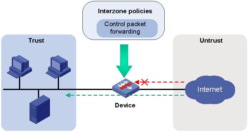
About interzone policies
Interzone policies identify data flows and control packet forwarding based on security zones, as shown in Figure 1. You can assign interfaces with the same security requirements to the same security zone, and assign interfaces with different security requirements to different security zones. For example, you can assign the interface connected to the internal network to security zone trust, and assign the interface connected to the Internet to security zone Untrust. Then, you can deploy interzone policies between the security zones to control packet forwarding.
If the network topology changes, you only need to change interface assignments. You do not need to modify the interzone policies.
Figure 1 Security zones and interzone policies
Interzone policy types
Interzone policies fall in to the following types: packet filtering, ASPF, and security policy. Packet filtering and ASPF can be applied on zone pairs. Security policies are based on security zones and are configured globally.
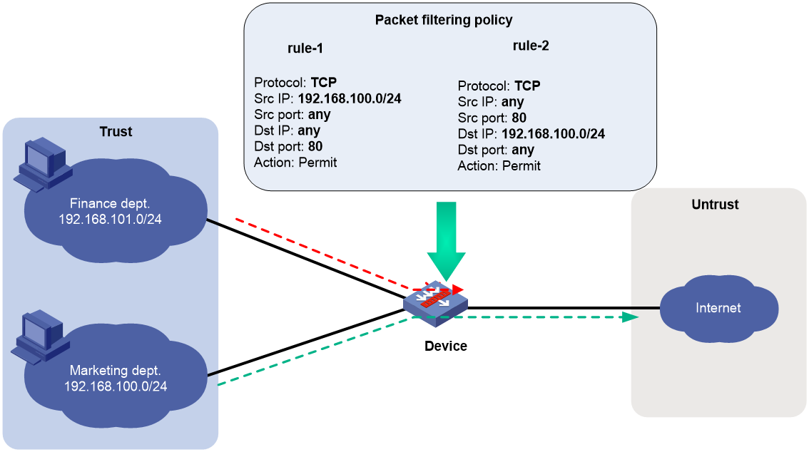
Packet filtering
Packet filtering controls packet forwarding between security zones by using packet quintuple information, including the source IP address, source port number, destination IP address, destination port number, and protocol number. For more information about packet filtering, see ACL configuration in ACL and QoS Configuration Guide.
As shown in Figure 2, to allow only employees in the Marketing department to access the Internet, configure rule-1 and rule-2. The default rule denies access requests from the Finance department. Then, apply packet filtering policies to both directions of the Trust-Untrust zone pair.
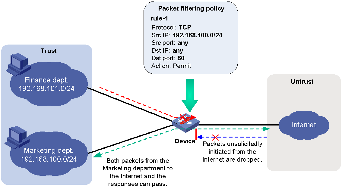
ASPF
Advanced Stateful Packet Filter (ASPF) records information about packets permitted by packet filtering policies to forward responses to the packets between security zones. For more information about ASPF, see "Configuring ASPF."
As shown in Figure 3, to allow only employees in the Marketing department to access the Internet, you can configure rule-1 and ASPF. The default rule denies access requests from the Finance department but also denies responses to packets from the Marketing department. ASPF enables the device to forward responses to packets from the Marketing department to the Marketing department.
Figure 3 Packet filtering and ASPF
Security policy
Security policies are configured globally and take effect globally. They can be used not only to replace packet filtering, but also to control packet forwarding based on users and applications. Security policies can also use DPI application profiles to perform DPI for matching packets. For more information about security policies, see "Configuring security policies."
As shown in Figure 4, to allow only employees in the Marketing department to access the Internet and forbid access to shopping websites, configure a security policy. The security policy can also implement DPI on web pages. The default rule denies access requests from the Finance department.
Figure 4 Security policy application

Advantages of security policies
As described in "Interzone policy types," security policies have the following advantages over the other types of interzone policies:
· More flexible and visible management—Security policies can identify packets based on not only quintuple information but also users.
· Precise and granular management—Security policies can identify packets based on protocols (for example, HTTP) and applications (for example, webpage-based games, videos, and shopping).
· DPI—By partnering with DPI, it can also provide security protection services such as antivirus and intrusion protection.
Restrictions and guidelines: Security zone configuration
Security policies take precedence over packet filtering policies. Packets matching security policies are processed based on the security policies.
Security zone configuration tasks at a glance
To configure security zones, perform the following tasks:
· Adding members to a security zone
· (Optional.) Specifying a permitted protocol
· (Optional.) Specifying the default action for packets between interfaces in the same security zone
· (Optional.) Enabling filtering based on virtual service IP address
Creating a security zone
1. Enter system view.
system-view
2. Create a security zone and enter security zone view.
security-zone name zone-name
By default, the device has the following security zones: Local, Trust, DMZ, Management, and Untrust.
Adding members to a security zone
About this task
A security zone can include member types listed in Table 1.
Table 1 Security zone members and objects that the members identify
|
Security zone member |
Objects that each member identifies |
|
Layer 3 interface: · Layer 3 Ethernet interface · Layer 3 logical interface, such as a Layer 3 subinterface |
All packets received or sent on the interface |
|
Layer 2 interface-VLAN combination |
All packets received or sent on the interface that carry the specified VLAN tag |
|
VLAN |
All packets that carry the specified VLAN tag. This type of security zones applies only to bridge forwarding. For more information about bridge forwarding, see bridge forwarding configuration in Layer 2—LAN Switching Configuration Guide. |
|
IPv4 subnet |
All packets sourced from or destined for the IPv4 subnet. |
|
IPv6 subnet |
All packets sourced from or destined for the IPv6 subnet. |
If a security zone has multiple types of members, a packet is matched in the following order: subnet, interface, and VLAN. The match operation stops when the first matching member is found.
Hardware and feature compatibility
On the default context, only security zone Management has interfaces by default.
The following compatibility matrix shows the default interfaces for security zone Management:
|
F1000 series |
Models |
Default interfaces |
|
F1000-X-G5 series |
F1000-E-G5, F1000-H-G5 |
M-GigabitEthernet 1/0/0 M-GigabitEthernet 1/0/1 |
|
F1000-A-G5, F1000-C-G5, F1000-C-G5-LI, F1000-S-G5 |
M-GigabitEthernet 1/0/0 |
|
|
F1000-X-G3 series |
F1000-A-G3, F1000-C-G3, F1000-E-G3, F1000-S-G3 |
M-GigabitEthernet 1/0/0 M-GigabitEthernet 1/0/1 |
|
F1000-X-G2 series |
F1000-A-G2, F1000-C-G2, F1000-E-G2, F1000-S-G2 |
GigabitEthernet 1/0/0 |
|
F1000-9X0-AI series |
F1000-9390-AI, F1000-9385-AI, F1000-9330-AI, F1000-9320-AI |
M-GigabitEthernet 1/0/0 M-GigabitEthernet 1/0/1 |
|
F1000-9380-AI, F1000-9370-AI, F1000-9360-AI, F1000-9350-AI |
M-GigabitEthernet 1/0/0 |
|
|
F1000-990-AI, F1000-980-AI, F1000-970-AI, F1000-960-AI, F1000-950-AI, F1000-930-AI, F1000-920-AI |
GigabitEthernet 1/0/0 |
|
|
F1000-910-AI, F1000-905-AI |
GigabitEthernet 1/0/0 GigabitEthernet 1/0/2 |
|
|
F1000-C83X0 series |
F1000-C8395, F1000-C8330 |
M-GigabitEthernet 1/0/0 M-GigabitEthernet 1/0/1 |
|
F1000-C8390, F1000-C8385, F1000-C8380, F1000-C8370, F1000-C8360, F1000-C8350 |
M-GigabitEthernet 1/0/0 |
|
|
F1000-C81X0 series |
F1000-C8180, F1000-C8170, F1000-C8160 |
GigabitEthernet 1/0/0 |
|
F1000-C8150, F1000-C8130, F1000-C8120, F1000-C8110 |
GigabitEthernet 1/0/0 GigabitEthernet 1/0/2 |
|
|
F1000-7X0-HI series |
F1000-770-HI, F1000-750-HI, F1000-740-HI |
M-GigabitEthernet 1/0/0 |
|
F1000-730-HI |
M-GigabitEthernet 1/0/0 M-GigabitEthernet 1/0/1 |
|
|
F1000-720-HI, F1000-710-HI |
GigabitEthernet 1/0/0 GigabitEthernet 1/0/2 |
|
|
F1000-C-X series |
F1000-C-EI, F1000-C-HI |
GigabitEthernet 1/0/0 |
|
F1000-C-XI, F1000-E-XI |
M-GigabitEthernet 1/0/0 |
|
|
F1000-V series |
F1000-E-VG |
GigabitEthernet 1/0/0 |
|
F1000-S-VG |
GigabitEthernet 1/0/0 GigabitEthernet 1/0/2 |
|
|
SecBlade IV |
LSPM6FWD8, LSQM2FWDSC8 |
GigabitEthernet 1/0/1 |
|
F100 series |
Models |
Default interfaces |
|
F100-X-G5 series |
F100-A-G5 |
M-GigabitEthernet 1/0/0 M-GigabitEthernet 1/0/1 |
|
F100-C-G5, F100-M-G5, F100-S-G5 |
GigabitEthernet 1/0/0 GigabitEthernet 1/0/2 |
|
|
F100-E-G5 |
M-GigabitEthernet 1/0/0 |
|
|
F100-X-G3 series |
F100-A-G3, F100-E-G3 |
GigabitEthernet 1/0/0 |
|
F100-C-G3, F100-M-G3, F100-S-G3 |
GigabitEthernet 1/0/0 GigabitEthernet 1/0/2 |
|
|
F100-X-G2 series |
F100-A-G2, F100-E-G2 |
GigabitEthernet 1/0/0 |
|
F100-C-G2, F100-M-G2, F100-S-G2 |
GigabitEthernet 1/0/0 GigabitEthernet 1/0/2 |
|
|
F100-WiNet series |
F100-A91-WiNet |
M-GigabitEthernet 1/0/0 |
|
F100-A81-WiNet |
M-GigabitEthernet 1/0/0 M-GigabitEthernet 1/0/1 |
|
|
F100-A80-WiNet |
GigabitEthernet 1/0/0 |
|
|
F100-C80-WiNet, F100-C60-WiNet, F100-C50-WiNet, F100-S80-WiNet |
GigabitEthernet 1/0/0 GigabitEthernet 1/0/2 |
|
|
F100-C-A series |
F100-C-A6, F100-C-A5, F100-C-A3, F100-C-A2, F100-C-A1 |
GigabitEthernet 1/0/0 GigabitEthernet 1/0/2 |
|
F100-C-A6-WL, F100-C-A5-W, F100-C-A3-W |
GigabitEthernet 1/0/0 |
|
|
F100-X-XI series |
F100-A-EI, F100-A-HI, F100-A-SI, F100-E-EI |
GigabitEthernet 1/0/0 |
|
F100-C-EI, F100-C-HI, F100-C-XI, F100-S-HI, F100-S-XI |
GigabitEthernet 1/0/0 GigabitEthernet 1/0/2 |
Procedure
1. Enter system view.
system-view
2. Enter security zone view.
security-zone name zone-name
3. Add members to the security zone.
Choose one option as needed:
¡ Add a Layer 3 Ethernet interface.
import interface layer3-interface-type layer3-interface-number
By default, a security zone does not have Layer 3 Ethernet interface members.
You can perform this step multiple times to add multiple Layer 3 Ethernet interface members.
¡ Add Layer 2 interface-VLAN combinations.
import interface layer2-interface-type layer2-interface-number vlan vlan-list
By default, a security zone does not have Layer 2 interface-VLAN combination members.
You can perform this step multiple times to add multiple Layer 2 interface-VLAN combination members.
¡ Add VLANs.
import vlan vlan-list
By default, a security zone does not have VLAN members.
You can perform this step multiple times to add multiple VLAN members.
¡ Add an IPv4 subnet.
import ip ip-address { mask-length | mask } [ vpn-instance vpn-instance-name ]
By default, a security zone does not have IPv4 subnet members.
You can perform this step multiple times to add multiple IPv4 subnet members.
¡ Add an IPv6 subnet.
import ipv6 ipv6-address prefix-length [ vpn-instance vpn-instance-name ]
By default, a security zone does not have IPv6 subnet members.
You can perform this step multiple times to add multiple IPv6 subnet members.
Specifying a permitted protocol
About this task
By default, the device permits packets only between security zones Local and Management. It denies packets between security zone Local and other security zones. To permit packets of the specified protocols between security zone Local and other security zones, you can specify permitted protocols on interfaces or configure interzone policies.
After you specify a permitted protocol on an interface, the device will permit packets of the specified protocol from the device that is connected to the interface. The packets will not be limited based on security policies or traffic policies.
You can configure the manage command multiple times to specify multiple permitted protocols.
Procedure
1. Enter system view.
system-view
2. Enter interface view.
interface interface-type interface-number
3. Specifying a permitted protocol.
manage { { http | https | ping | ssh | telnet } { inbound | outbound } | { netconf-http | netconf-https | netconf-ssh | snmp } inbound }
By default, no permitted protocols are specified. The device permits packets only from other devices that are connected through interfaces in security zone Management.
Creating a zone pair
About this task
A zone pair has a source security zone and a destination security zone. The device examines received first data packets and uses zone pairs to identify data flows. Then, the device uses interzone policies applied to the matching zone pairs to process the data flows.
You can use the zone-pair security source any destination any command to define the any-to-any zone pair. This zone pair matches all packets from one security zone to another security zone. A zone pair between specific security zones has a higher priority than the any-to-any zone pair.
For packets between the Management and Local security zones, the device uses only interzone policies applied to the zone pairs of the two security zones. By default, the device forwards packets between the Management and Local zones.
Procedure
1. Enter system view.
system-view
2. Create a zone pair and enter zone pair view.
zone-pair security source { source-zone-name | any } destination { destination-zone-name | any }
Specifying the default action for packets between interfaces in the same security zone
About this task
The system uses the default action for packets that are exchanged between interfaces in the same security zone in the following situations:
· A zone pair from the security zone to the security zone itself is not configured.
· A zone pair from the security zone to the security zone itself is configured, but no interzone policy is applied to the zone pair.
Hardware and feature compatibility
|
F1000 series |
Models |
Feature compatibility |
|
F1000-X-G5 series |
F1000-A-G5, F1000-C-G5, F1000-C-G5-LI, F1000-S-G5 |
No |
|
F1000-E-G5, F1000-H-G5 |
Yes |
|
|
F1000-X-G3 series |
F1000-A-G3, F1000-C-G3, F1000-E-G3, F1000-S-G3 |
Yes |
|
F1000-X-G2 series |
F1000-A-G2, F1000-C-G2, F1000-E-G2, F1000-S-G2 |
Yes |
|
F1000-9X0-AI series |
F1000-9390-AI, F1000-9385-AI, F1000-990-AI, F1000-980-AI, F1000-970-AI, F1000-960-AI, F1000-950-AI, F1000-930-AI, F1000-920-AI, F1000-910-AI, F1000-905-AI |
Yes |
|
F1000-9380-AI, F1000-9370-AI, F1000-9360-AI, F1000-9350-AI, F1000-9330-AI, F1000-9320-AI |
No |
|
|
F1000-C83X0 series |
F1000-C8395, F1000-C8390 |
Yes |
|
F1000-C8370, F1000-C8360, F1000-C8350, F1000-C8385, F1000-C8380, F1000-C8330 |
No |
|
|
F1000-C81X0 series |
F1000-C8180, F1000-C8170, F1000-C8160, F1000-C8150, F1000-C8130, F1000-C8120, F1000-C8110 |
Yes |
|
F1000-7X0-HI series |
F1000-770-HI, F1000-750-HI, F1000-740-HI, F1000-730-HI |
No |
|
F1000-720-HI, F1000-710-HI |
Yes |
|
|
F1000-C-X series |
F1000-C-EI, F1000-C-HI |
Yes |
|
F1000-C-XI, F1000-E-XI |
No |
|
|
F1000-V series |
F1000-E-VG, F1000-S-VG |
Yes |
|
SecBlade IV |
LSPM6FWD8, LSQM2FWDSC8 |
Yes |
|
F100 series |
Models |
Feature compatibility |
|
F100-X-G5 series |
F100-E-G5, F100-A-G5, F100-C-G5, F100-M-G5, F100-S-G5 |
Yes |
|
F100-X-G3 series |
F100-A-G3, F100-E-G3, F100-C-G3, F100-M-G3, F100-S-G3 |
Yes |
|
F100-X-G2 series |
F100-A-G2, F100-E-G2, F100-C-G2, F100-M-G2, F100-S-G2 |
Yes |
|
F100-WiNet series |
F100-A80-WiNet, F100-C80-WiNet, F100-C60-WiNet, F100-C50-WiNet, F100-S80-WiNet |
Yes |
|
F100-A91-WiNet, F100-A81-WiNet |
No |
|
|
F100-C-A series |
F100-C-A6, F100-C-A5, F100-C-A3, F100-C-A2, F100-C-A1, F100-C-A6-WL, F100-C-A5-W, F100-C-A3-W |
Yes |
|
F100-X-XI series |
F100-A-EI, F100-A-HI, F100-A-SI, F100-E-EI, F100-C-EI, F100-C-HI, F100-C-XI, F100-S-HI, F100-S-XI |
Yes |
Procedure
1. Enter system view.
system-view
2. Specify the default action for packets exchanged between interfaces in the same security zone.
¡ Set the default action to permit.
security-zone intra-zone default permit
¡ Set the default action to deny.
undo security-zone intra-zone default permit
By default, the default action is deny.
Enabling filtering based on virtual service IP address
About this task
This feature enables the device to filter packets from external networks to internal servers by virtual service IP address in scenarios where server load balancing is deployed. By default, this feature is disabled. Before matching each of the packets against ACLs, the device translates the destination IP address (the virtual service IP address) to the real server IP address. For more information about packet filtering, see ACL configuration in ACL and QoS Configuration Guide.
Procedure
1. Enter system view.
system-view
2. Enable filtering based on virtual service IP address for zone pairs.
zone-pair vsip-filter enable
By default, filtering based on virtual service IP address is disabled.
Display and maintenance commands for security zones
Execute display commands in any view.
|
Task |
Command |
|
Display security zone information. |
display security-zone [ name zone-name ] |
|
Display zone pair information. |
display zone-pair security |
Security zone configuration examples
Example: Configuring security zones
Network configuration
As shown in Figure 5, a security protection device (Device) connects the corporate network to the Internet. The corporate network needs to provide Web services for only internal users.
To ensure corporate network security, configure the device as follows:
· Assign GigabitEthernet 1/0/1, GigabitEthernet 1/0/2, and GigabitEthernet 1/0/3 to security zones Trust, DMZ, and Untrust, respectively.
· Configure zone pairs and apply interzone policies to control access as follows:
¡ Allow internal users to access the Web server and the Internet.
¡ Forbid external users to access the internal network and the Web server.
¡ Forbid the Web server to access the internal network.

Procedure
1. Assign IP address to the interfaces.
# Assign an IP address to GigabitEthernet 1/0/1.
<Device> system-view
[Device] interface gigabitethernet 1/0/1
[Device-GigabitEthernet1/0/1] ip address 1.1.1.1 255.255.255.0
[Device-GigabitEthernet1/0/1] quit
# Assign IP addresses to other interfaces in the same way. (Details not shown.)
2. Add interfaces to security zones.
[Device] security-zone name trust
[Device-security-zone-Trust] import interface gigabitethernet 1/0/1
[Device-security-zone-Trust] quit
[Device] security-zone name dmz
[Device-security-zone-DMZ] import interface gigabitethernet 1/0/2
[Device-security-zone-DMZ] quit
[Device] security-zone name untrust
[Device-security-zone-Untrust] import interface gigabitethernet 1/0/3
[Device-security-zone-Untrust] quit
3. Configure ACLs.
# Configure ACL 3001 to allow internal hosts to access the Internet.
[Device] acl advanced 3001
[Device-acl-ipv4-adv-3500] rule permit ip source 1.1.1.0 0.0.0.255 destination 3.3.3.0 0.0.0.255
[Device-acl-ipv4-adv-3500] quit
# Configure ACL 3002 to allow internal hosts to access the Web server.
[Device] acl advanced 3002
[Device-acl-ipv4-adv-3002] rule permit ip source 1.1.1.0 0.0.0.255 destination 2.2.2.0 0.0.0.255
[Device-acl-ipv4-adv-3500] quit
4. Configure zone pairs.
# Create a zone pair with the source security zone Trust and destination security zone Untrust. Apply ACL 3001 to the zone pair.
[Device] zone-pair security source trust destination untrust
[Device-zone-pair-security-Trust-Untrust] packet-filter 3001
[Device-zone-pair-security-Trust-Untrust] quit
# Create a zone pair with the source security zone Trust and destination security zone DMZ. Apply ACL 3002 to the zone pair.
[Device] zone-pair security source trust destination dmz
[Device-zone-pair-security-Trust-DMZ] packet-filter 3002
[Device-zone-pair-security-Trust-DMZ] quit
Verifying the configuration
# Verify that internal hosts can access the Internet and the Web server. (Details not shown.)
# Verify that access requests initiated from the Internet and the DMZ zone to the internal network are denied. (Details not shown.)
