- Table of Contents
- Related Documents
-
| Title | Size | Download |
|---|---|---|
| 02-SRv6 configuration | 490.00 KB |
Directing traffic to an SRv6 tunnel
SR microloop avoidance after a network failure
SR microloop avoidance after a failure recovery
Restrictions: Hardware compatibility with SRv6
Using IGP to advertise SRv6 SIDs
Configuring a BGP-EPE SRv6 peer set
Specifying an SID list for an SRv6 tunnel interface
Configuring a service class for an SRv6 tunnel interface
Enabling BFD echo-mode detection on an SRv6 tunnel interface
Configuring traffic forwarding
Configuring a static route to direct traffic to an SRv6 tunnel
Configuring automatic static route advertisement to direct traffic to an SRv6 tunnel
Configuring automatic IGP route advertisement to direct traffic to an SRv6 tunnel
Disabling an interface from participating in TI-LFA calculation
Configuring SR microloop avoidance
Display and maintenance commands for SRv6
Example: Configuring SRv6 that uses End SIDs
Example: Configuring SRv6 that uses End.X SIDs
Example: Configuring IPv6 IS-IS TI-LFA FRR
Configuring SRv6
About SRv6
Segment Routing (SR) is a source routing technology. The source node selects a path for packet forwarding, and then encodes the path in the packet header as an ordered list of segments. Each segment is identified by the Segment Identifier (SID). The SR nodes along the path forward the packets based on the SIDs in the packets. Only the source node needs to maintain the path status.
IPv6 Segment Routing (SRv6) uses IPv6 addresses as SIDs to forward packets.
Basic concepts
SR node
An SR node is a node that supports the SRv6 feature. The ingress node (source node) selects a path for packet forwarding, encodes the path as an ordered SID list in the routing extension header. The transit nodes forward the packets based on the SID list. The egress node removes the routing extension header and forwards the packets to the destination.
SID
SRv6 supports SRv6 SIDs that have specific functions.
An SRv6 SID is in the format of IPv6 address, but the IPv6 address does not belong to any interface on any device.
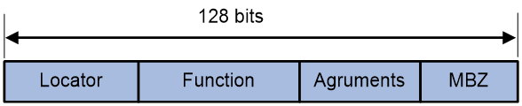
As shown in Figure 1, an SRv6 SID contains the Locator, Function, Arguments, and Must be zero (MBZ) portions.
· Locator—Identifies the network segment of the SID. The locator of an SRv6 SID must be unique in the SR domain.
· Function—Contains an opcode that identifies the network function of an SID. An SR node will execute the function in the SRv6 SID Function field of an SRv6 packet after it receives that SRv6 packet.
· Arguments—Defines flow and service parameters for SRv6 packets.
· MBZ—When the total number of bits in the Locator, Function, and Arguments portions is less than 128 bits, the remaining bits are padded with 0s.
According to the functions of SRv6 SIDs, SRv6 SIDs are divided into the following categories:
· End SID—Identifies the prefix of a destination address in the network.
· End.X SID—Identifies a link in the network.
· End.DT4 SID—Identifies an IPv4 VPN in the network. The function of an End.DT4 SID is decapsulating packets and searching the routing table of the corresponding IPv4 VPN instance to forward the packets. End.DT4 SIDs are applicable to MPLS L3VPN and EVPN L3VPN scenarios.
· End.DT6 SID—Identifies an IPv6 VPN in the network. The function of an End.DT6 SID is decapsulating packets and searching the routing table of the corresponding IPv6 VPN instance to forward the packets. End.DT6 SIDs are applicable to IPv6 MPLS L3VPN and IPv6 EVPN L3VPN scenarios.
· End.DT46 SID—Identifies an IPv4 or IPv6 VPN in the network.
· End.DX4 SID—Identifies an IPv4 next hop in the network. The function of an End.DX4 SID is decapsulating packets and forwarding the decapsulated IPv4 packets out of the Layer 3 interface bound to the SID to a specific next hop. End.DX4 SIDs are applicable to MPLS L3VPN over SRv6, EVPN L3VPN over SRv6, and public network IPv4 over SRv6 scenarios.
· End.DX6 SID—Identifies an IPv6 next hop in the network. The function of an End.DX6 SID is decapsulating packets and forwarding the decapsulated IPv6 packets out of the Layer 3 interface bound to the SID to a specific next hop. End.DX6 SIDs are applicable to MPLS L3VPN over SRv6, EVPN L3VPN over SRv6, and public network IPv6 over SRv6 scenarios.
· End.OP SID—Applies to the SRv6 OAM scenario. For more information about End.OP SIDs, see "Configuring SRv6 OAM."
Use IGP to advertise SRv6 SIDs for an SR node. The other SR nodes will generate route entries of that SR node based on the advertised information.
SRv6 SID flavors
Use SRv6 SID flavors to change the forwarding behaviors of SRv6 SIDs in order to meet multiple service requirements. The following SRv6 SID flavors are supported:
· Penultimate Segment POP of the SRH (PSP)—The penultimate SRv6 node removes the SRH to reduce the workload of the end SRv6 node and improve the forwarding efficiency. The end SRv6 node does not read the SRH, and it only looks up the local SID table for the destination IPv6 address of packets to forward the packets.
· NO PSP—The penultimate SRv6 node does not remove the SRH.
Local SID forwarding table
An SRv6-enabled node maintains a local SID forwarding table that records the SRv6 SIDs generated on the local node. The local SID forwarding table has the following functions:
· Stores local generated SRv6 SID forwarding information.
· Stores SRv6 SID operation types.
Segment List
A Segment List is an ordered list of SIDs, which is also referred to as a Segment Identifier (SID) list in this document. The SR nodes forward packets based on the SIDs in the order that they are arranged in the SID list.
SRv6 tunnel
An SRv6 tunnel is a virtual point-to-point connection established between the SRv6 ingress node and egress node. IPv6 packets are encapsulated at the ingress node and de-encapsulated at the egress node.
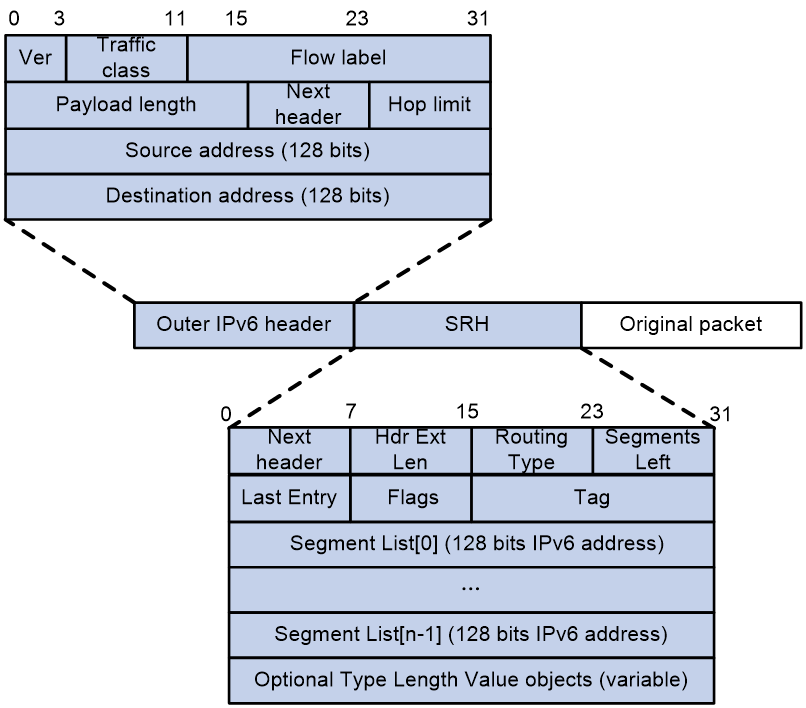
SRv6 packet format
An outer IPv6 header and a Segment Routing Header (SRH) are added to the original Layer 3 data packet to form an SRv6 packet.
As shown in Figure 2, the value for the Next Header field is 43 in the outer IPv6 header, which indicates that the header next to the IPv6 header is a routing extension header. The value for the Routing Type field in the routing extension header is 4, which indicates that the routing extension header is an SRH. The SRH header contains the following fields:
· 8-bit Next Header—Identifies the type of the header next to the SRH.
· 8-bit Hdr Ext Len—Length of the SRH header in 8-octet units, not including the first 8 octets.
· 8-bit Routing Type—The value for this field is 4, which represents SRH.
· 8-bit Segments Left—Contains the index of the next segment to inspect in the Segment List. The Segments Left field is set to n-1 where n is the number of segments in the Segment List. Segments Left is decremented at each segment.
· 8-bit Last Entry—Contains the index of the first SID in the path used to forward the packet.
· 8-bit Flags—Contains flags.
· 16-bit Tag—Tags a packet as part of a class or group of packets, for example, packets sharing the same set of properties.
· Segment List—Contains 128-bit IPv6 addresses representing the ordered segments. The Segment List is encoded starting from the last segment of the path. The first element of the segment list (Segment List [0]) contains the last segment of the path, the second element (Segment List [1]) contains the penultimate segment of the path and so on. The number enclosed in a pair of brackets is the index of a segment.
SRv6 packet forwarding
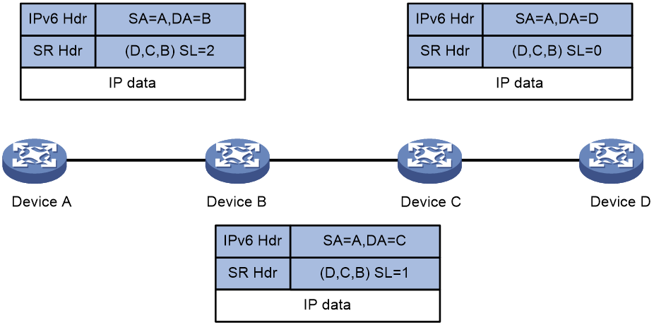
As shown in Figure 3, an IPv6 packet is forwarded through an SRv6 tunnel as follows:
1. Upon receiving an IPv6 packet, Device A finds in the routing table that the outgoing interface is an SRv6 tunnel interface. The packet is delivered to the tunnel interface.
2. The SRv6 tunnel interface encapsulates the IPv6 packet as follows:
¡ Adds an SRH header. The Segments Left (SL) value is the number of segments minus one. The path from ingress to egress has three segments, so the SL value is set to 2. The encapsulated SID list is Segment List [0]=D, Segment List [1]=C, Segment List [2]=B. The Segment List is encoded starting from the last segment of the path to the first segment of the path.
¡ Adds an outer IPv6 header. The source address is the tunnel source, and the destination address is determined by the SL value. On Device A, the SL value is 2, which points to the IPv6 address of Device B, so the destination address is the IPv6 address of Device B.
3. Device A searches the routing table for the destination address in the newly encapsulated IPv6 header, and forwards the packet to Device B.
4. Device B first checks the destination address and SID type in the outer IPv6 header.
¡ If the SID type is End.X, the device obtains the output interface and next hop information based on the End.X SID.
¡ If the SID is not End.X, the device does not perform any operation.
Then, the device checks the SL value in the SRH header and decreases the value by one. Then, the device searches for the IPv6 address pointed by Segment List [1] and uses the IPv6 address of Device C to replace the destination address of the outer IPv6 header.
5. Device B performs one of the following operations depending on the SID type:
¡ For an End.X SID, the device forwards the encapsulated packet to Device C based on the obtained output interface and next hop information.
¡ For an SID of the other type, the device searches the routing table for the destination address in the outer IPv6 header and forwards the packet to Device C.
6. Device C performs the same operations as what Device B has done in steps 4 and 5, and then forwards the packet to Device D.
7. Device D checks the SL value in the SRH header and finds that the value has decreased to 0. The device performs the following operations:
a. De-encapsulates the packet by removing the outer IPv6 header and the SRH header.
b. Forwards the original IP data packet to the destination based on the destination address.
Figure 3 SRv6 tunnel packet forwarding
Directing traffic to an SRv6 tunnel
After an SRv6 tunnel is established, traffic is not forwarded on the tunnel automatically. You must direct the traffic to the tunnel by configuring a static route or automatic route advertisement.
Static routing
You can direct traffic to an SRv6 tunnel by creating a static route that reaches the destination through the tunnel interface on the source node. This is the easiest way to implement SRv6 tunnel forwarding. When traffic to multiple networks is to be forwarded through the SRv6 tunnel, you must configure multiple static routes, resulting in increased configuration and maintenance workloads.
For more information about static routing, see Layer 3—IP Routing Configuration Guide.
Automatic route advertisement
Automatic route advertisement distributes the SRv6 tunnel to the IGP (OSPF or IS-IS), so the SRv6 tunnel can participate in IGP route calculation. Automatic route advertisement is easy to configure and maintain.
Automatic route advertisement can be implemented by using the following methods:
· IGP shortcut—Also known as AutoRoute Announce. It considers the SRv6 tunnel as a link that directly connects the tunnel ingress node and the egress node. Only the ingress node uses the SRv6 tunnel during IGP route calculation.
· Forwarding adjacency—Considers the SRv6 tunnel as a link that directly connects the tunnel ingress node and the egress node, and advertises the link to the network through an IGP. Every node in the network uses the SRv6 tunnel during IGP route calculation.
|
|
IMPORTANT: Only IGP shortcut is supported in the current software version. |
As shown in Figure 4, an SRv6 tunnel exists from Device D to Device C. IGP shortcut enables only the ingress node Device D to use the SRv6 tunnel in IGP route calculation. Device A cannot use this tunnel to reach Device C. With forwarding adjacency enabled, Device A can learn this SRv6 tunnel and transfer traffic to Device C by forwarding the traffic to Device D.
Figure 4 IGP shortcut and forwarding adjacency diagram
BGP-EPE
IGP for SRv6 cannot advertise SRv6 SIDs across ASs. To advertise SRv6 SIDs across ASs, use BGP Egress Peer Engineering (BGP-EPE).
BGP-EPE can allocate BGP peer SIDs to inter-AS segments.
· If the device has established BGP LS peer relationship with a network controller, it advertises the peer SIDs to the network controller through extended BGP LS messages. Then, the controller orchestrates the IGP SIDs and BGP peer SIDs to realize optimal inter-AS traffic forwarding.
· If the device has not established BGP LS peer relationship with a network controller, it advertises the peer SIDs to a BGP peer through BGP LS messages. When a device that has established BGP LS peer relationship with a network controller receives the peer SIDs, it advertises the peer SIDs to the network controller through BGP LS messages.
BGP-EPE supports automatic peer SID allocation and static peer SID allocation. As shown in Figure 5, BGP-EPE can allocate the following peer SIDs:
· PeerNode SID—Identifies a peer node. BGP-EPE allocates a PeerNode SID to each BGP session. If the device establishes EBGP peer relationship with a peer through a loopback interface, it might have multiple physical links to reach the peer. In this case, the PeerNode SID for this peer is associated with multiple output interfaces. Traffic destined for this peer based on the PeerNode SID will be distributed among these output interfaces.
· PeerAdj SID—Identifies an adjacency link that can reach a peer node. If the device establishes EBGP peer relationship with a peer through a loopback interface, it might have multiple physical links to reach the peer. Each link is allocated a PeerAdj SID. When the device forwards traffic based on a PeerAdj SID, the traffic is forwarded out of the interface that is attached to the link identified by the PeerAdj SID.
· PeerNode-Adj SID—Identifies a peer node and identifies one or multiple adjacency links that can reach a peer node.
· PeerSet SID—Identifies a group of peer nodes in a BGP-EPE SRv6 peer set. A PeerSet SID corresponds to multiple PeerNode SIDs and PeerAdj SIDs. When the device forwards traffic based on a PeerSet SID, it distributes the traffic among multiple peers.
Figure 5 BGP-EPE network diagram
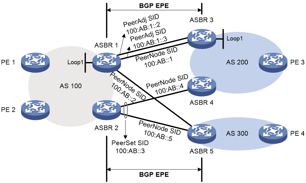
As shown in Figure 5, BGP-EPE allocates peer SIDs as follows:
· ASBR 1 and ASBR 3 have two direct physical links. They establish EBGP peer relationship through loopback interfaces. On ASBR 1, BGP-EPE allocates PeerNode SID 100:AB::1 to ASBR 3 and allocates PeerAdj SIDs 100:AB:1::2 and 100:AB:1::3 to the physical links. When ASBR 1 forwards traffic to ASBR 3 based on the PeerNode SID, the two physical links load share the traffic.
· EBGP peer relationship has been established between ASBR 1 and ASBR 5, between ARBR 2 and ASBR 4, and between ASBR 2 and ASBR 5 through directly connected physical interfaces. On ASBR 1, BGP-EPE allocates PeerNode SID 100:AB::2 to ASBR 5. On ASBR 2, BGP-EPE allocates PeerNode SIDs 100:AB::4 and 100:AB::5 to ASBR 4 and ASBR 5, respectively.
· ASBR 4 and ASBR 5 each has established EBGP peer relationship with ASBR 2. On ASBR 2, peers ASBR 4 and ASBR 5 are added to a peer set. BGP-EPE allocates PeerSet SID 100:AB::3 to the peer set. When ASBR 2 forwards traffic based on the PeerSet SID, the traffic is distributed to both ASBR 4 and ASBR 5 for load sharing.
The SIDs allocated to peers by BGP-EPE are not advertised to the peers. Route types used by the peers do not affect BGP-EPE.
TI-LFA FRR
Topology-Independent Loop-Free Alternate Fast Re-Route (TI-LFA FRR) provides link and node protection for SRv6 tunnels. When a link or node fails, TI-LFA FRR switches the traffic to the backup path to ensure continuous data forwarding.
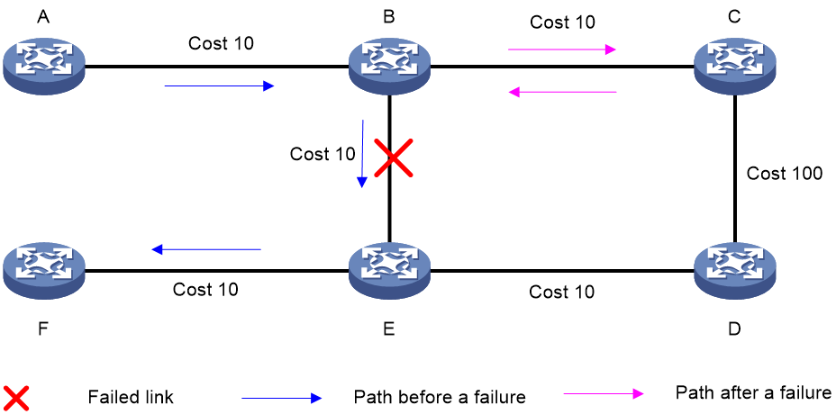
TI-LFA FRR background
As shown in Figure 6, node A sends data packets to node F. When the link between node B and node E fails, node B forwards the data packets to node C. The cost of the link between node C and node D is 100 (which is greater than the cost of the link between node C and node D) and the routes on node C have not converged. As a result, node C determines that the next hop of the optimal path to reach node F is node B. Then, node C forwards the data packets back to node B, which causes a loop.
Figure 6 TI-LFA application scenario
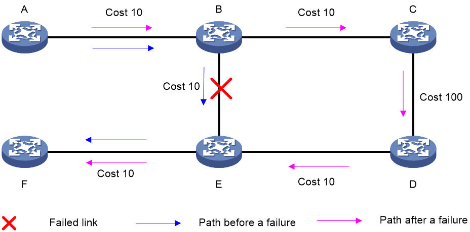
To resolve this issue, deploy TI-FLA on the SRv6 network. As shown in Figure 7, when the link between node B and node E fails, node B uses the backup path calculated by TI-LFA to forward the data packets along the B->C->D->E path.
Figure 7 TI-LFA forwarding network diagram
TI-LFA FRR concepts
· P space—Use the source node of the protected link as the root to establish a shortest path tree. All nodes that are reachable from the source node without passing the protected link form the P space. Nodes in the P space are called P nodes.
· Extended P space—Use the source node of the protected link and its neighbors as the roots to establish shortest path trees. All nodes that are reachable from the source node or one of its neighbors without passing the protected link form the extended P space. The P space is a subset of the extended P space.
· Q space—Use the destination node of the protected link as the root to establish a reverse shortest path tree. All nodes that are reachable from the root node without passing the protected link form the Q space. Nodes in the Q space are called Q nodes.
· Repair list—A constraint path used to indicate how a P node reaches a Q node when the P space and Q space do not have common nodes. The repair list contains the following SRv6 SIDs:
¡ SRv6 SIDs of P nodes.
¡ SRv6 SIDs from P nodes to nearest Q nodes.
TI-LFA FRR protection types
The following TI-LFA traffic protection types are available:
· Link protection—Protects traffic that traverses a specific link.
· Node protection—Protects traffic that traverses a specific node.
Node protection takes precedence over link protection.
TI-LFA FRR path calculation
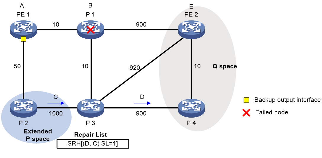
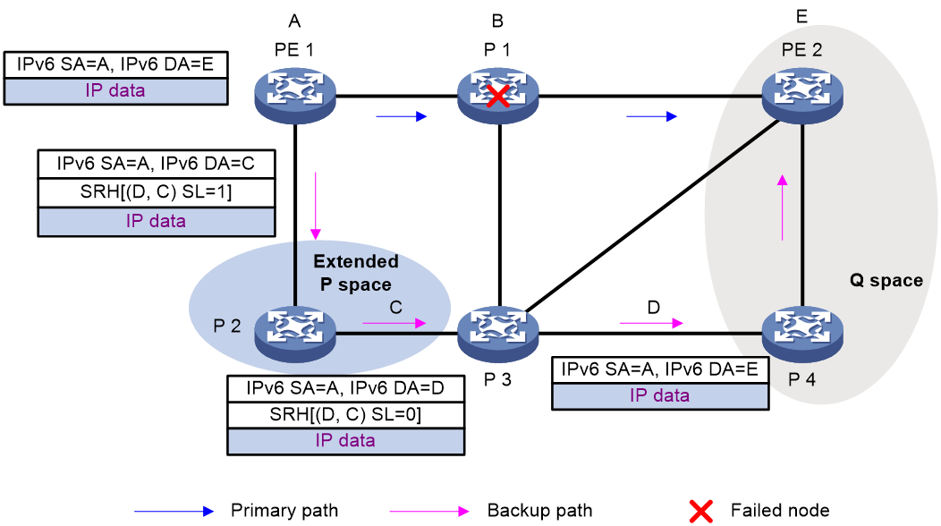
As shown in Figure 8, PE 1 is the source node. P 1 is the faulty node. PE 2 is the destination node. The numbers on links represent the link costs. A data flow traverses PE 1, P 1, and PE 2. To protect data against P 1 failure, TI-LFA FRR calculates the extended P space, Q space, shortest path tree converged after P 1 fails, repair list, and backup output interface, and creates the backup forwarding entry.
TI-LFA FRR calculates the backup path by using the following steps:
1. Calculates the extended P space: P 2.
2. Calculates the Q space: PE 2 and P 4.
3. Calculates the shortest path tree converged after P 1 fails: PE 1 --> P 2 --> P 4 --> PE 2.
4. Calculates the repair list: End.X SID C of the link between P 2 and P 3 and End.X SID D of the link between P 3 and P 4.
5. Calculates the backup output interface, that is, the output interface to the next hop after the link from PE 1 to P 1 fails.
TI-LFA FRR forwarding process
After TI-LFA FRR finishes backup path calculation, traffic will be switched to the backup path in response to a primary path failure.
As shown in Figure 9, P 2 is a P node and P 4 and PE 2 are Q nodes. When the next hop on the primary path (P 1) fails, TI-LFA FRR switches the traffic to the backup path. The following are the detailed steps:
1. PE 1 looks up the IPv6 routing table for the destination IPv6 address of a packet and finds that the next hop is P 2. PE 1 encapsulates the packet according to the repair list.
¡ Adds an SRH header. The SID list is Segment List [0]=D and Segment List [1]=C. The SIDs are arranged from the farthest node to the nearest node.
¡ Adds an outer IPv6 header. The source address is address A on source node PE 1 and the destination address is the address pointed by SL. Because the SL is 1, the destination address is C as pointed by Segment List [1].
2. After P2 receives the packet, it performs the following operations:
a. Checks the SL value in the SRH header and decreases the value by 1.
b. Searches for the address pointed by Segment List [0] and finds that the address is End.X SID D between P 3 and P 4.
c. Replaces the destination address in the outer IPv6 header with End.X SID D.
d. Obtains the output interface and next hop according to End.X SID C and forwards the encapsulated packet to P 3.
3. After P3 receives the packet, it performs the following operations:
a. Checks the SL value in the SRH header and finds that the SL value is 0.
b. Decapsulates the packet.
c. Obtains the output interface and next hop according to End.X SID D and forwards the packet to P 4.
4. After P4 receives the packet, it searches the IP routing table for the destination IP address of the packet and forwards the packet to PE 2.
Figure 9 Data forwarding over the TI-LFA FRR backup path
SR microloop avoidance after a network failure
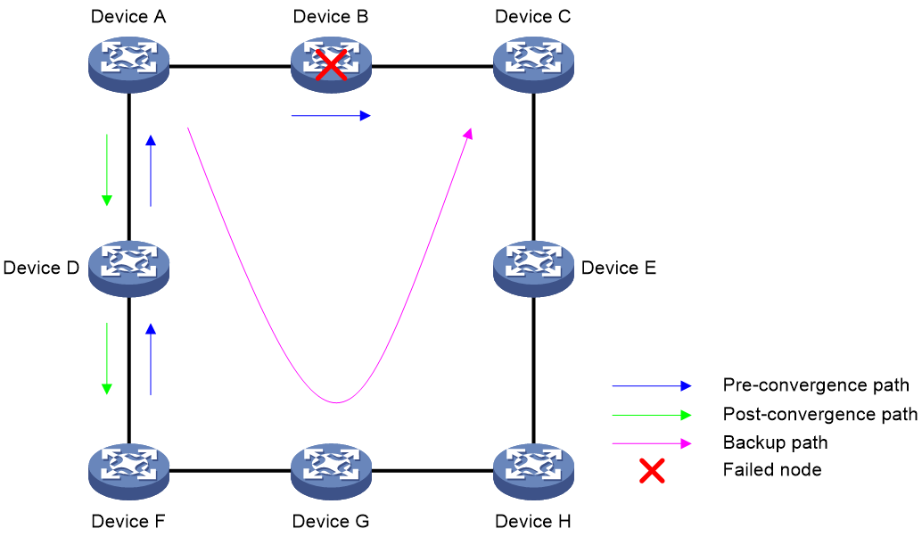
As shown in Figure 10, when Device B fails, traffic to Device C will be switched to the backup path calculated by TI-LFA. After Device A finishes route convergence, traffic will be switched to the post-convergence path. If Device D and Device F have not finished route convergence and still forward traffic along the pre-convergence path, a loop is formed between Device A and Device F. The loop exists until Device D and Device F finish route convergence.
SR microloop avoidance can resolve this issue. After you configure TI-LFA, Device A first switches traffic to the backup path calculated by TI-LFA when Device B fails. Then, Device A waits for Device D and Device F to finish route convergence before starting route convergence. After Device A also finishes route convergence, Device A switches the traffic to the converged route.
Figure 10 Diagram for SR microloop avoidance after a network failure
SR microloop avoidance after a failure recovery
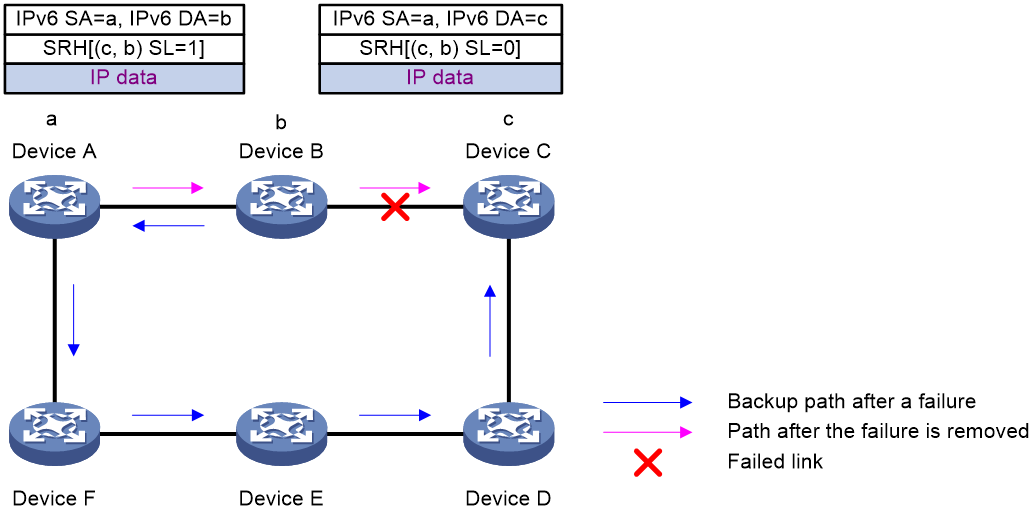
As shown in Figure 11, before the link between Device B and Device C recovers, traffic traverses along the backup path. After the link recovers, Device A forwards the traffic to Device B if Device A finishes route convergence before Device B. With route convergence unfinished, Device B still forwards the traffic along the backup path. A loop is formed between Device A and Device B.
SR microloop avoidance can resolve this issue. After the link recovers, SR microloop avoidance automatically calculates the optimal path from Device A to Device C and forwards traffic along the path. To forward a packet along the newly calculated path, Device A adds, for example, the adjacency SID from Device B to Device C, to the packet and then sends the packet to Device B. Then, Device B forwards the packet to Device C based on the path information.
Upon expiration of the microloop avoidance RIB-update-delay timer and completion of route convergence on Device B, Device A does not add path information to packets anymore. It will forward packets to Device C as usual.
Figure 11 Diagram for SR microloop avoidance after a failure recovery
Protocols and standards
· draft-previdi-6man-segment-routing-header
· draft-ietf-6man-segment-routing-header
· draft-filsfils-spring-segment-routing
· draft-filsfils-spring-srv6-network-programming
Restrictions: Hardware compatibility with SRv6
|
Hardware |
SRv6 compatibility |
|
MSR810, MSR810-W, MSR810-W-DB, MSR810-LM, MSR810-W-LM, MSR810-10-PoE, MSR810-LM-HK, MSR810-W-LM-HK, MSR810-LM-CNDE-SJK, MSR810-CNDE-SJK |
Yes |
|
MSR810-LMS, MSR810-LUS |
No |
|
MSR810-LMS-EA, MSR810-LME |
Yes |
|
MSR1004S-5G |
Yes |
|
MSR2600-6-X1, MSR2600-10-X1, MSR2600-15-X1 |
Yes |
|
MSR 2630 |
Yes |
|
MSR3600-28, MSR3600-51 |
Yes |
|
MSR3600-28-SI, MSR3600-51-SI |
No |
|
MSR3600-28-X1, MSR3600-28-X1-DP, MSR3600-51-X1, MSR3600-51-X1-DP |
Yes |
|
MSR3610-I-DP, MSR3610-IE-DP, MSR3610-IE-ES, MSR3610-IE-EAD, MSR-EAD-AK770, MSR3610-I-IG, MSR3610-IE-IG |
Yes |
|
MSR3610-X1, MSR3610-X1-DP, MSR3610-X1-DC, MSR3610-X1-DP-DC, MSR3620-X1, MSR3640-X1 |
Yes |
|
MSR3610, MSR3620, MSR3620-DP, MSR3640, MSR3660 |
Yes |
|
MSR3610-G, MSR3620-G |
Yes |
|
MSR3640-X1-HI |
Yes |
|
Hardware |
SRv6 compatibility |
|
MSR810-W-WiNet, MSR810-LM-WiNet |
Yes |
|
MSR830-4LM-WiNet |
Yes |
|
MSR830-5BEI-WiNet, MSR830-6EI-WiNet, MSR830-10BEI-WiNet |
Yes |
|
MSR830-6BHI-WiNet, MSR830-10BHI-WiNet |
Yes |
|
MSR2600-6-WiNet, MSR2600-10-X1-WiNet |
Yes |
|
MSR2630-WiNet |
Yes |
|
MSR3600-28-WiNet |
Yes |
|
MSR3610-X1-WiNet |
Yes |
|
MSR3610-WiNet, MSR3620-10-WiNet, MSR3620-DP-WiNet, MSR3620-WiNet, MSR3660-WiNet |
Yes |
|
Hardware |
SRv6 compatibility |
|
MSR2630-XS |
Yes |
|
MSR3600-28-XS |
Yes |
|
MSR3610-XS |
Yes |
|
MSR3620-XS |
Yes |
|
MSR3610-I-XS |
Yes |
|
MSR3610-IE-XS |
Yes |
|
MSR3620-X1-XS |
Yes |
|
MSR3640-XS |
Yes |
|
MSR3660-XS |
Yes |
|
Hardware |
SRv6 compatibility |
|
MSR810-LM-GL |
Yes |
|
MSR810-W-LM-GL |
Yes |
|
MSR830-6EI-GL |
Yes |
|
MSR830-10EI-GL |
Yes |
|
MSR830-6HI-GL |
Yes |
|
MSR830-10HI-GL |
Yes |
|
MSR1004S-5G-GL |
Yes |
|
MSR2600-6-X1-GL |
Yes |
|
MSR3600-28-SI-GL |
No |
SRv6 tasks at a glance
To configure SRv6, perform the following tasks:
2. Using IGP to advertise SRv6 SIDs
This task is required in an inter-AS network.
Perform the following tasks on the source node of an SRv6 tunnel:
b. Specifying an SID list for an SRv6 tunnel interface
c. (Optional.) Configuring a service class for an SRv6 tunnel interface
d. (Optional.) Enabling BFD echo-mode detection on an SRv6 tunnel interface
5. (Optional.) Configuring traffic forwarding
6. (Optional.) Configuring TI-LFA FRR
7. (Optional.) Configuring the SRv6 path MTU
Prerequisites for SRv6
Before you configure an SRv6 tunnel, perform the following tasks:
· Determine the ingress node, transit nodes, and egress node of the SRv6 tunnel.
· Plan the IPv6 address of each SR node.
Configuring an SRv6 SID
About this task
An SRv6 SID is in the format of IPv6 address and it contains 128 bits. An SRv6 SID contains the Locator, Function, and Args portions.
· The Locator portion is determined by the ipv6-prefix ipv6-address prefix-length parameter. The portion length is determined by the prefix-length argument. A locator is an IPv6 subnet. All IPv6 addresses in the subnet can be used as SRv6 SIDs.
· The Function portion contains an opcode. The opcode can be a static opcode or a dynamic opcode.
¡ Static opcode—Manually configured by using the opcode command. SRv6 SIDs generated based on a static opcode are static SRv6 SID. The length of a static opcode is determined by the static static-length option, and it determines the number of static SRv6 SIDs on the locator.
¡ Dynamic opcode—Dynamically allocated by IGP or BGP. SRv6 SIDs generated based on a dynamic opcode are dynamic SRv6 SID. When dynamically allocating SRv6 SIDs, IGP or BGP applies for SIDs outside the static opcode range to avoid SRv6 SID conflicts.
· The Args portion contains traffic flow and service information. This portion is determined by the args args-length option.
The length of a dynamic opcode is calculated by using the following formula: dynamic-length = 128 - (prefix-length + static-length + args-length).
A static SRv6 SID is generated based on the following formula: static SRv6 SID = ipv6-prefix + 0 + opcode + 0.
· The ipv6-prefix portion represents the IPv6 prefix specified by using theipv6-address and prefix-length arguments in the locator command. The number of bits occupied by the IPv6 prefix is configured by using the prefix-length argument.
· The number of bits occupied by 0s (following the ipv6-prefix portion) is the value of the dynamic-length argument.
· The opcode portion represents the opcode. The number of bits occupied by the opcode is configured by using the static-length argument in the locator command.
· The number of bits occupied by 0s (following the opcode portion) is the value of the args-length argument.
A dynamic SRv6 SID is generated based on the following formula: dynamic SRv6 SID = ipv6-prefix + dynamic + 0.
· The ipv6-prefix portion represents the IPv6 prefix specified by using the ipv6-address and prefix-length arguments in the locator command. The number of bits occupied by the IPv6 prefix is configured by using the prefix-length argument.
· The dynamic portion is dynamically allocated by IGP or BGP. The number of bits occupied by this portion is the value of the dynamic-length argument.
· The number of bits occupied by 0s is the sum value of the static-length and args-length arguments.
For example, in the locator test1 ipv6-prefix 100:200:DB8:ABCD:: 64 static 24 args 32 command:
· The Locator portion is 100:200:DB8:ABCD::. This portion occupies 64 bits.
· The static opcode occupies 24 bits.
· The Args portion occupies 32 bits.
· The dynamic opcode occupies 8 bits.
The static SRv6 SID range and dynamic SRv6 SID range are as follows:
· The start static SRv6 SID is 100:200:DB8:ABCD:0:1::.
· The end static SRv6 SID is 100:200:DB8:ABCD:FF:FFFF::.
· The start dynamic SRv6 SID is 100:200:DB8:ABCD:100::.
· The end dynamic SRv6 SID is 100:200:DB8:ABCD:FFFF:FFFF::.
Restrictions and guidelines
Each locator must have a unique name.
Do not configure the same IPv6 address prefix and prefix length for different locators. In addition, the IPv6 address prefixes of different locators cannot overlap.
You cannot disable SRv6 or delete a locator in SRv6 view if the locator has dynamic SRv6 SIDs that are being used.
Procedure
1. Enter system view.
system-view
2. Enable SRv6 and enter SRv6 view.
segment-routing ipv6
3. Configure a locator and enter SRv6 locator view.
locator locator-name [ ipv6-prefix ipv6-address prefix-length [ args args-length | static static-length ] * ]
4. Configure an opcode. Perform one of the following tasks:
¡ Configure an End SID.
opcode opcode end [ no-psp ]
¡ Configure an End.X SID.
opcode opcode end-x interface interface-type interface-number nexthop nexthop-ipv6-address [ no-psp ]
¡ Configure an End.DT4 SID.
opcode opcode end-dt4 [ vpn-instance vpn-instance-name [ evpn ] ]
The specified VPN instance must exist. An End.DT4 SID cannot be configured in different VPN instances.
¡ Configure an End.DT6 SID.
opcode opcode end-dt6 [ vpn-instance vpn-instance-name [ evpn ] ]
The specified VPN instance must exist. An End.DT6 SID cannot be configured in different VPN instances.
¡ Configure an End.DT46 SID.
opcode opcode end-dt46 [ vpn-instance vpn-instance-name [ evpn ] ]
The specified VPN instance must exist. An End.DT46 SID cannot be configured in different VPN instances.
¡ Configure an End.DX4 SID.
opcode opcode end-dx4 interface interface-type interface-number nexthop nexthop-ipv4-address [ vpn-instance vpn-instance-name [ evpn ] ]
The specified VPN instance must exist. An End.DX4 SID cannot be configured with different output interfaces or next hops.
¡ Configure an End.DX6 SID.
opcode opcode end-dx6 interface interface-type interface-number nexthop nexthop-ipv6-address [ vpn-instance vpn-instance-name [ evpn ] ]
The specified VPN instance must exist. An End.DX6 SID cannot be configured with different output interfaces or next hops.
¡ Configure an End.OP SID.
opcode opcode end-op
Using IGP to advertise SRv6 SIDs
About this task
Use an IGP protocol to advertise the SRv6 SID of a locator by applying the locator to the IGP protocol.
Prerequisites
If IS-IS is used to advertise SRv6 SIDs, make sure the cost style of IS-IS is wide, compatible, or wide-compatible. For more information about the cost styles of IS-IS, see Layer 3—IP Routing Configuration Guide.
Using IS-IS to advertise SRv6 SIDs
1. Enter system view.
system-view
2. Enter IS-IS process view.
isis [ process-id ] [ vpn-instance vpn-instance-name ]
3. Enter IS-IS IPv6 address family view.
address-family ipv6 [ unicast ]
4. Apply a locator to IS-IS IPv6 address family.
segment-routing ipv6 locator locator-name [ level-1 | level-2 ] [ auto-sid-disable ]
By default, no locators are applied to IS-IS IPv6 address family.
Repeat this command to apply multiple locators to IS-IS IPv6 address family for the family to advertise multiple SRv6 SIDs.
Using OSPFv3 to advertise SRv6 SIDs
1. Enter system view.
system-view
2. Enter OSPFv3 process view.
ospfv3 [ process-id | vpn-instance vpn-instance-name ] *
3. Apply a locator to the OSPFv3 process.
segment-routing ipv6 locator locator-name [ auto-sid-disable ]
By default, no locators are applied to an OSPFv3 process.
Repeat this command to apply multiple locators to the OSPFv3 process for the process to advertise multiple SRv6 SIDs.
Configuring BGP-EPE
Enabling SRv6 BGP-EPE
About this task
BGP-EPE allocates BGP peer SIDs to inter-AS segments. The device advertises the peer SIDs to a network controller through BGP LS messages. The controller orchestrates the IGP SIDs and BGP peer SIDs to realize optimal inter-AS traffic forwarding.
With this feature, the device can allocate SRv6 SIDs to its connected BGP peers or peer groups to identify its connected BGP peers or links.
Restrictions and guidelines
If you do not specify any parameters for the peer egress-engineering srv6 command, the device will dynamically allocate SRv6 SIDs to peers. The SRv6 SIDs belong to the locator specified by using the segment-routing ipv6 egress-engineering locator command in BGP instance view.
When you use the peer egress-engineering srv6 command for a peer, follow these restrictions and guidelines:
· If you use this command to specify multiple locators for that peer, only the most recent configuration takes effect.
· If you use this command to specify multiple static SRv6 SIDs and the SIDs belong to different types, all types of SRv6 SIDs can take effect. For the same type of SRv6 SIDs, only the most recent configuration takes effect.
If you specify a static SRv6 SID for a peer, the specified static SRv6 SID must belong to the locator specified by using the segment-routing ipv6 egress-engineering locator command in BGP instance view.
The static SRv6 SIDs specified by using the following commands cannot be the same:
· peer egress-engineering srv6.
· egress-engineering srv6 peer-set.
Procedure
1. Enter system view.
system-view
2. Enter BGP instance view.
bgp as-number [ instance instance-name ]
3. Enable SRv6 BGP-EPE.
peer group-name egress-engineering srv6
peer ipv6-address [ prefix-length ] egress-engineering srv6 [ locator locator-name | static-sid { psp psp-sid | no-psp-usp no-psp-usp-sid } * ]
By default, SRv6 BGP-EPE is disabled.
Applying a locator to BGP-EPE
About this task
Perform this task to restrict the range of End.X SIDs that can be allocated to BGP-EPE SRv6 peer sets and BGP-EPE-enabled peers in a BGP instance. All static SRv6 SIDs configured for the BGP-EPE SRv6 peer sets and peers must belong to the locator specified by performing this task.
Restrictions and guidelines
To dynamically allocate End.X SIDs from the specified locator:
· Do not configure a static SRv6 SID when you create a BGP-EPE SRv6 peer set by using the egress-engineering srv6 peer-set command.
· Do not specify a locator or configure a static SRv6 SID when you enable SRv6 BGP-EPE for a peer by using the peer egress-engineering srv6 command.
Procedure
1. Enter system view.
system-view
2. Enter BGP instance view.
bgp as-number [ instance instance-name ]
3. Apply a locator to BGP-EPE.
segment-routing ipv6 egress-engineering locator locator-name
By default, no locator is applied to BGP-EPE.
Configuring a BGP-EPE SRv6 peer set
About this task
If the device establishes BGP peer relationship with multiple devices, perform this task to add the peer devices to a peer set and allocate a PeerSet SID to the peer set. When the device forwards traffic based on the PeerSet SID, it distributes the traffic among the peers for load sharing.
Prerequisites
Enable SRv6 BGP-EPE on all peers that will be added to the BGP-EPE SRv6 peer set.
Use the segment-routing ipv6 egress-engineering locator command in BGP instance view to apply a locator to BGP-EPE.
· If automatic SID allocation is used, the device dynamically allocates an SRv6 SID to the BGP-EPE SRv6 peer set from the specified locator.
· If you specify a static SRv6 SID for the BGP-EPE SRv6 peer set, the specified static SRv6 SID must belong to the specified locator.
If you execute the egress-engineering srv6 peer-set command to specify multiple SRv6 SIDs for one peer set, the effective configuration depends on whether the SRv6 SIDs are the same type.
· If all the SRv6 SIDs belong to the same type, only the most recent configuration takes effect.
· If the SRv6 SIDs belong to different types, the configuration for all the SRv6 SID types takes effect. For the SRv6 SIDs that belong to the same type, only the most recent configuration takes effect. Make sure each SRv6 SID is unique among all the SRv6 SID types.
The static SRv6 SIDs configured by using the following commands cannot be the same:
· egress-engineering srv6 peer-set.
· peer egress-engineering srv6.
Procedure
1. Enter system view.
system-view
2. Enter BGP instance view.
bgp as-number [ instance instance-name ]
3. Create a BGP-EPE SRv6 peer set.
egress-engineering srv6 peer-set peer-set-name [ static-sid { psp psp-sid | no-psp-usp no-psp-usp-sid } * ]
4. Add a peer to the BGP-EPE SRv6 peer set.
peer { ipv6-address [ prefix-length ] } peer-set srv6-peer-set-name
By default, no peers are added to a BGP-EPE SRv6 peer set.
To change the BGP-EPE SRv6 peer set for a peer, you must first use undo peer peer-set command to remove that peer from the original BGP-EPE SRv6 peer set.
Configuring SRv6 tunneling
Configuring an SID list
About this task
An SR node is uniquely identified by an SID index in an SID list. The SID list forms a forwarding path. The SR nodes in the list are arranged by SID index in ascending sort order. When the device encapsulates the Segment List, SRv6 automatically assigns a segment index to each SR node based on their SID indexes. The smallest SID index corresponds to the largest segment index, and the largest SID index corresponds to the smallest segment index.
Restrictions and guidelines
If you do not specify an SID index for an SR node, SRv6 automatically assigns an SID index to the node. The assigned SID index is the largest index that has been assigned plus an increment.
Make sure the node nearest to the source node is assigned the smallest SID index. The nearer a node is to the source node, the smaller the SID index value of the node must be.
If changing settings for an SID list will cause the tunnel that uses this SID list to go down, the device does not issue the changed settings until route convergence is complete.
Procedure
1. Enter system view.
system-view
2. Create an SID list and enter its view.
ipv6 segment-routing sid-list list-name
3. Configure an SR node in the SID list.
sid [ index index-number ] ipv6-address
To make the node reachable by other nodes, configure IGP on the node to advertise the SRv6 SID of the node.
Specifying an SID list for an SRv6 tunnel interface
1. Enter system view.
system-view
2. Create an SRv6 tunnel interface and enter its view.
interface tunnel tunnel-number mode sr ipv6
3. Specify an SID list for the tunnel interface.
tunnel sid-list list-name [ backup ]
By default, no SID lists are specified for an SRv6 tunnel interface.
Configuring a service class for an SRv6 tunnel interface
About this task
Class Based Tunnel Selection (CBTS) compares the service class value of the traffic with the service class values of SRv6 tunnels. CBTS uses the following rules to select a tunnel to forward the traffic:
· If the traffic matches an SRv6 tunnel, CBTS uses this tunnel.
· If the traffic matches multiple SRv6 tunnels, CBTS selects a tunnel based on the flow forwarding mode set on the tunnel interface.
¡ If flow-based forwarding is set, CBTS randomly selects a matching tunnel for packets of the same flow.
¡ If packet-based forwarding is set, CBTS uses all matching tunnels to load share the packets.
· If the traffic does not match any SRv6 tunnels, CBTS selects an SRv6 tunnel from all tunnels with a service class value smaller than the traffic. Among these tunnels, the one with the largest service class value is used. If all SRv6 tunnels have a service class value greater than the traffic, CBTS uses the tunnel with the smallest service class value.
Procedure
1. Enter system view.
system-view
2. Enter SRv6 tunnel interface view.
interface tunnel tunnel-number [ mode sr ipv6 ]
3. Configure a service class for the tunnel interface.
service-class class-value
By default, no service class is configured for an SRv6 tunnel interface.
Enabling BFD echo-mode detection on an SRv6 tunnel interface
About this task
Perform this task on an SRv6 tunnel interface to use BFD sessions for quick link connectivity detection of the SRv6 tunnel. If a link failure is detected along the path, the device can quickly handle the issue, for example, it can direct the traffic to the backup path to ensure traffic forwarding continuity.
If the BFD session of a path is down, the path is unavailable. If the BFD session of a path is up, the path is available.
Procedure
1. Enter system view.
system-view
2. Configure the source IPv6 address of BFD echo packets.
bfd echo-source-ipv6 ipv6-address
By default, no source IPv6 address is configured for BFD echo packets.
As a best practice, do not configure the source IPv6 address to be on the same network segment as any local interfaces. If you configure such a source IPv6 address, a large number of ICMPv6 redirect packets might be sent from the peer, resulting in link congestion. For more information about this command, see BFD in High Availability Configuration Guide.
3. Enter SRv6 tunnel interface view.
interface tunnel tunnel-number [ mode sr ipv6 ]
4. Enable BFD echo-mode detection.
tunnel bfd enable echo
By default, BFD echo-mode detection is disabled on an SRv6 tunnel interface.
Configuring traffic forwarding
Configuring a static route to direct traffic to an SRv6 tunnel
For information about the command to configure a static route, see Layer 3—IP Routing Command Reference. The interface specified in this command must be an SRv6 tunnel interface.
Configuring automatic static route advertisement to direct traffic to an SRv6 tunnel
About this task
Perform this task on an SRv6 tunnel interface to create a static route whose destination address and output interface are the tunnel destination address and the tunnel interface, respectively.
Procedure
1. Enter system view.
system-view
2. Enter SRv6 tunnel interface view.
interface tunnel tunnel-number [ mode sr ipv6 ]
3. Configure automatic static route advertisement.
tunnel route-static [ preference preference-value ]
By default, automatic static route advertisement is not configured.
Configuring automatic IGP route advertisement to direct traffic to an SRv6 tunnel
About this task
To direct traffic to an SRv6 tunnel, you can distribute the SRv6 tunnel to the IGP and make the SRv6 tunnel participate in IGP route calculation. To achieve these purposes, deploy the following functionalities:
· IPv6 router ID.
The IPv6 router ID determines the source and destination addresses of the SRv6 tunnel distributed to the IGP. The destination address of the SRv6 tunnel must be the same as the IPv6 router ID of the destination node.
Configuring an IPv6 route ID on a router also enables the IPv6 TE feature on that router. After the SRv6 tunnel participates in IGP route calculation, traffic can be directed to the SRv6 tunnel.
· Automatic route advertisement.
This functionality distributes the SRv6 tunnel to the IGP and makes the SRv6 tunnel participate in IGP route calculation.
Restrictions and guidelines for directing traffic to an SRv6 tunnel
The IPv6 router ID must be unique in the IPv6 network.
To avoid routing loops in a ring topology when a link on the SRv6 tunnel is down, set the SIDs in the SID list of the SRv6 tunnel to have 128-bit prefixes. IGP does not set the output interface of a host route to the SRv6 tunnel interface.
Prerequisites for directing traffic to an SRv6 tunnel
Before you configure the IPv6 router ID for IS-IS, make sure the cost style of IS-IS is wide, compatible, or wide-compatible. For more information about the cost styles of IS-IS, see Layer 3—IP Routing Configuration Guide.
Before you configure automatic route advertisement, you must enable IPv6 capability for the IGP protocol on the SRv6 tunnel interface.
Configuring the IPv6 router ID and enabling IPv6 TE
1. Enter system view.
system-view
2. Enter IS-IS view.
isis [ process-id ] [ vpn-instance vpn-instance-name ]
3. Enter IS-IS IPv6 address family view.
address-family ipv6 [ unicast ]
4. Configure the IPv6 router ID for IS-IS and enable IPv6 TE.
router-id ipv6-address
By default, no IPv6 router ID is configured for IS-IS and IPv6 TE is disabled.
Configuring IGP shortcut
1. Enter system view.
system-view
2. Enter SRv6 tunnel interface view.
interface tunnel tunnel-number mode sr ipv6
3. Enable IGP shortcut.
srv6 igp shortcut [ isis | ospf ]
By default, IGP shortcut is disabled.
Only IS-IS supports IGP shortcut in the current software version.
4. Assign a metric to the SRv6 tunnel.
srv6 igp metric { absolute value | relative value }
By default, the metric of an SRv6 tunnel equals its IGP metric.
Configuring TI-LFA FRR
TI-LFA FRR tasks at a glance
To configure TI-LFA FRR, perform the following tasks:
2. (Optional.) Disabling an interface from participating in TI-LFA calculation
On the source node, disable TI-LFA on the route's output interface to the next hop on the primary path.
3. (Optional.) Configuring SR microloop avoidance
Enabling TI-LFA FRR
Enabling IPv6 IS-IS TI-LFA FRR
1. Enter system view.
system-view
2. Enter IS-IS view.
isis process-id
3. Enter IS-IS IPv6 unicast address family view.
address-family ipv6
4. Enable LFA FRR for IPv6 IS-IS.
fast-reroute lfa [ level-1 | level-2 ]
By default, LFA FRR is disabled for IPv6 IS-IS.
5. Enable TI-LFA FRR for IPv6 IS-IS.
fast-reroute ti-lfa [ per-prefix ] [ route-policy route-policy-name | host ] [ level-1 | level-2 ]
By default, TI-LFA FRR is disabled for IPv6 IS-IS.
Enabling OSPFv3 TI-LFA FRR
1. Enter system view.
system-view
2. Enter OSPFv3 view.
ospfv3 [ process-id | vpn-instance vpn-instance-name ] *
3. Enable LFA FRR for OSPFv3.
fast-reroute { lfa [ abr-only ] | route-policy route-policy-name }
By default, LFA FRR is disabled for OSPFv3.
4. Enable TI-LFA FRR for OSPFv3.
fast-reroute ti-lfa [ per-prefix ] [ route-policy route-policy-name | host ]
By default, TI-LFA FRR is disabled for OSPFv3.
Disabling an interface from participating in TI-LFA calculation
Disabling an IPv6 IS-IS interface from participating in TI-LFA calculation
1. Enter system view.
system-view
2. Enter the view of IPv6 IS-IS interface.
interface interface-type interface-number
3. Disable the interface from participating in TI-LFA calculation.
isis ipv6 fast-reroute ti-lfa disable [ level-1 | level-2 ]
By default, an IPv6 IS-IS interface participates in TI-LFA calculation.
Disabling an OSPFv3 interface from participating in TI-LFA calculation
1. Enter system view.
system-view
2. Enter the view of OSPFv3 interface.
interface interface-type interface-number
3. Disable the interface from participating in TI-LFA calculation.
ospfv3 fast-reroute ti-lfa disable [ instance instance-id ]
By default, an OSPFv3 interface participates in TI-LFA calculation.
Configuring SR microloop avoidance
About this task
SR microloop avoidance provides microloop avoidance after both a network failure and a failure recovery.
After a network failure occurs or recovers, route convergence occurs on relevant network devices. Because of nonsimultaneous convergence on network devices, microloops might be formed. After you configure SR microloop avoidance, the devices will forward traffic along the specified path before route convergence is finished on all the relevant network devices. Because the forwarding path is independent of route convergence, microloops are avoided.
To ensure sufficient time for IGP to complete route convergence, set the SR microloop avoidance RIB-update-delay time. Before the timer expires, faulty relevant devices will forward traffic along the specified path. Upon expiration of the timer and completion of IGP route convergence, traffic will traverse along the IGP-calculated path.
Configuring IPv6 IS-IS SR microloop avoidance
1. Enter system view.
system-view
2. Enter IS-IS view.
isis process-id
3. Enter IS-IS IPv6 unicast address family view.
address-family ipv6
4. Enable SR microloop avoidance for IPv6 IS-IS.
segment-routing microloop-avoidance enable [ level-1 | level-2 ]
By default, SR microloop avoidance is disabled for IPv6 IS-IS.
5. (Optional.) Set the SR microloop avoidance RIB-update-delay time.
segment-routing microloop-avoidance rib-update-delay delay-time [ level-1 | level-2 ]
By default, the SR microloop avoidance RIB-update-delay time is 5000 ms.
Configuring OSPFv3 SR microloop avoidance
1. Enter system view.
system-view
2. Enter OSPFv3 process view.
ospfv3 [ process-id | vpn-instance vpn-instance-name ] *
3. Enable SR microloop avoidance for OSPFv3.
segment-routing microloop-avoidance enable
By default, SR microloop avoidance is disabled for OSPFv3.
4. (Optional.) Set the SR microloop avoidance RIB-update-delay time.
segment-routing microloop-avoidance rib-update-delay delay-time
By default, the SR microloop avoidance RIB-update-delay time is 5000 ms.
Configuring the SRv6 path MTU
About this task
This task specifies the maximum bytes that can be contained in an SRv6 tunneled packets.
The transit nodes do not fragment SRv6 tunneled packets. If a packet is larger than the MTU of the output interface, the packet will be discarded. If the MTU is too small, the bandwidth is not sufficiently used. To address these issues, configure an appropriate SRv6 path MTU.
Procedure
1. Enter system view.
system-view
2. Enter SRv6 view.
segment-routing ipv6
3. Configure the SRv6 path MTU.
path-mtu mtu-value
By default, the SRv6 path MTU is 1500 bytes.
Display and maintenance commands for SRv6
Execute display commands in any view.
|
Task |
Command |
|
Display BGP-EPE information for IPv6 peers. |
display bgp [ instance instance-name ] egress-engineering ipv6 [ ipv6-address ] |
|
Display information about BGP-EPE SRv6 peer sets. |
display bgp egress-engineering srv6 peer-set [ srv6-peer-set-name ] |
|
Display SID list information. |
display ipv6 segment-routing sid-list [ list-name ] |
|
Display IS-IS SRv6 capability information. |
display isis segment-routing ipv6 capability [ level-1 | level-2 ] [ process-id ] |
|
Display IS-IS SRv6 locator routing information. |
display isis segment-routing ipv6 locator [ ipv6-address prefix-length ] [ [ level-1 | level-2 ] | verbose ] * [ process-id ] |
|
Display IS-IS SRv6 tunnel interface information. |
display isis srv6 tunnel [ level-1 | level-2 ] [ process-id ] |
|
Display OSPFv3 SRv6 capability information. |
display ospfv3 [ process-id ] segment-routing ipv6 capability |
|
Display OSPFv3 SRv6 tunnel interface information. |
display ospfv3 [ process-id ] srv6 tunnel [ interface-number ] |
|
Display SRv6 forwarding entries. |
In standalone mode: display segment-routing ipv6 forwarding [ entry-id ] In IRF mode: display segment-routing ipv6 forwarding [ entry-id ] [ slot slot-number ] |
|
Display information about the SRv6 local SID forwarding table. |
display segment-routing ipv6 local-sid { end | end-b6encaps | end-dt4 | end-dt46 | end-dt6 | end-dx4 | end-dx6 | end-op | end-x } [ sid ] |
|
Display SRv6 locator information. |
display segment-routing ipv6 locator [ locator-name ] |
SRv6 configuration examples
Example: Configuring SRv6 that uses End SIDs
Network configuration
As shown in Figure 12, run OSPFv3 on Router A, Router B, and Router C. Set up an SRv6 tunnel between Router A and Router C.

Table 1 Interface and IP address assignment
|
Device |
Interface |
IP address |
Device |
Interface |
IP address |
|
Router A |
Loop0 |
1::9/128 |
Router C |
Loop0 |
5::9/128 |
|
|
GE1/0/2 |
1::1/64 |
|
GE1/0/2 |
2::2/64 |
|
Router B |
Loop0 |
2::9/128 |
|
|
|
|
|
GE1/0/1 |
1::2/64 |
|
|
|
|
|
GE1/0/2 |
2::1/64 |
|
|
|
Procedure
1. Configure IPv6 addresses and masks for the interfaces. (Details not shown.)
2. Configure OSPFv3 to advertise routes for the interfaces, including the loopback interfaces. (Details not shown.)
Execute the display ipv6 routing-table command on each router to verify that they have obtained routes to reach one another, including the host routes of loopback interfaces.
3. Configure Router A:
# Configure SRv6 End SIDs.
[RouterA] segment-routing ipv6
[RouterA-segment-routing-ipv6] locator aa ipv6-prefix 100:1::1 120 static 8
[RouterA-segment-routing-ipv6-locator-aa] opcode 1 end
[RouterA-segment-routing-ipv6-locator-aa] quit
[RouterA-segment-routing-ipv6] quit
# Configure OSPFv3 to advertise the SRv6 SIDs.
[RouterA] ospfv3 1
[RouterA-ospfv3-1] segment-routing ipv6 locator aa
[RouterA-ospfv3-1] quit
# Configure SID list a and specify Router B and Router C as nodes in the list.
[RouterA] ipv6 segment-routing sid-list a
[RouterA-srv6-sid-list-a] sid 200:1::1
[RouterA-srv6-sid-list-a] sid 300:1::1
[RouterA-srv6-sid-list-a] quit
# Create SRv6 tunnel interface Tunnel 0 on Router A. Specify Loopback 0 as the source interface, specify the IP address of Loopback 0 on Router C as the destination, configure an IPv6 address for the tunnel interface, and apply SID list a to the SRv6 tunnel.
[RouterA] interface tunnel 0 mode sr ipv6
[RouterA-Tunnel0] source loopback 0
[RouterA-Tunnel0] destination 5::9
[RouterA-Tunnel0] ipv6 address 6::6 64
[RouterA-Tunnel0] tunnel sid-list a
[RouterA-Tunnel0] quit
# Configure a static route to direct traffic destined for Router C to the SRv6 tunnel.
[RouterA] ipv6 route-static 99::1 64 tunnel 0
4. Configure Router B:
# Configure SRv6 End SIDs.
[RouterB] segment-routing ipv6
[RouterB-segment-routing-ipv6] locator bb ipv6-prefix 200:1::1 120 static 8
[RouterB-segment-routing-ipv6-locator-bb] opcode 1 end
[RouterB-segment-routing-ipv6-locator-bb] quit
[RouterB-segment-routing-ipv6] quit
# Configure OSPFv3 to advertise the SRv6 SIDs.
[RouterB] ospfv3 1
[RouterB-ospfv3-1] segment-routing ipv6 locator bb
[RouterB-ospfv3-1] quit
5. Configure Router C:
# Configure SRv6 End SIDs.
[RouterC] segment-routing ipv6
[RouterC-segment-routing-ipv6] locator cc ipv6-prefix 300:1::1 120 static 8
[RouterC-segment-routing-ipv6-locator-cc] opcode 1 end
[RouterC-segment-routing-ipv6-locator-cc] quit
[RouterC-segment-routing-ipv6] quit
# Configure OSPFv3 to advertise the SRv6 SIDs.
[RouterC] ospfv3 1
[RouterC-ospfv3-1] segment-routing ipv6 locator cc
[RouterC-ospfv3-1] quit
# Configure an SID list, SRv6 tunnel, and static route on Router C in the same way as the settings are configured on Router A. The SID list, SRv6 tunnel, and static route on Router C are from Router C to Router A. (Details not shown.)
Verifying the configuration
# Verify the SID list information on Router A.
[RouterA] display ipv6 segment-routing sid-list
SID list name: a
SID information:
SID index Address
5 200:1::1
9 300:1::1
SID list usage on tunnels:
Tunnel number SID list role
0 Primary
Verify that the traffic destined for 99::1 is forwarded through the SRv6 tunnel.
[Router A] display ipv6 fib 99::1
FIB entry count: 1
Flag:
U:Usable G:Gateway H:Host B:Blackhole D:Dynamic S:Static
R:Relay F:FRR
Destination: 99:: Prefix length: 64
Nexthop : :: Flags: US
Time stamp : 0x10 Label: Null
Interface : Tun0 Token: Invalid
Example: Configuring SRv6 that uses End.X SIDs
Network configuration
As shown in Figure 13, run OSPFv3 on Router A, Router B, and Router C. Set up an SRv6 tunnel between Router A and Router C.
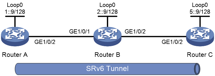
Table 2 Interface and IP address assignment
|
Device |
Interface |
IP address |
Device |
Interface |
IP address |
|
Router A |
Loop0 |
1::9/128 |
Router C |
Loop0 |
5::9/128 |
|
|
GE1/0/2 |
1::1/64 |
|
GE1/0/2 |
2::2/64 |
|
Router B |
Loop0 |
2::9/128 |
|
|
|
|
|
GE1/0/1 |
1::2/64 |
|
|
|
|
|
GE1/0/2 |
2::1/64 |
|
|
|
Procedure
1. Configure IPv6 addresses and masks for the interfaces. (Details not shown.)
2. Configure OSPFv3 to advertise routes for the interfaces, including the loopback interfaces. (Details not shown.)
Execute the display ipv6 routing-table command on each router to verify that they have obtained routes to reach one another, including the host routes of loopback interfaces.
3. Configure Router A:
# Configure SRv6 End.X SIDs.
[RouterA] segment-routing ipv6
[RouterA-segment-routing-ipv6] locator a1 ipv6-prefix 100:1::1:0 120 static 8
[RouterA-segment-routing-ipv6-locator-a1] opcode 1 end-x interface gigabitethernet 1/0/2 nexthop 1::2
[RouterA-segment-routing-ipv6-locator-a1] quit
[RouterA-segment-routing-ipv6] quit
# Configure OSPFv3 to advertise the SRv6 SIDs.
[RouterA] ospfv3 1
[RouterA-ospfv3-1] segment-routing ipv6 locator a1
[RouterA-ospfv3-1] quit
# Configure SID list A and specify Router B and Router C as nodes in the list.
[RouterA] ipv6 segment-routing sid-list A
[RouterA-srv6-sid-list-A] sid 200:1::1:1
[RouterA-srv6-sid-list-A] sid 300:1::1:1
[RouterA-srv6-sid-list-A] quit
# Create SRv6 tunnel interface Tunnel 0 on Router A. Specify Loopback 0 as the source interface, specify the IP address of Loopback 0 on Router C as the destination, configure an IPv6 address for the tunnel interface, and apply SID list A to the SRv6 tunnel.
[RouterA] interface tunnel 0 mode sr ipv6
[RouterA-Tunnel0] source loopback 0
[RouterA-Tunnel0] destination 5::9
[RouterA-Tunnel0] ipv6 address 7::7 64
[RouterA-Tunnel0] tunnel sid-list A
[RouterA-Tunnel0] quit
# Configure a static route to direct traffic destined for Router C to the SRv6 tunnel.
[RouterA] ipv6 route-static 199::1 64 tunnel 0
4. Configure Router B:
# Configure SRv6 End.X SIDs.
[RouterB] segment-routing ipv6
[RouterB-segment-routing-ipv6] locator b1 ipv6-prefix 200:1::1:0 120 static 8
[RouterB-segment-routing-ipv6-locator-b1] opcode 1 end-x interface gigabitethernet 1/0/2 nexthop 2::2
[RouterB-segment-routing-ipv6-locator-b1] quit
[RouterB-segment-routing-ipv6] quit
# Configure OSPFv3 to advertise the SRv6 SIDs.
[RouterB] ospfv3 1
[RouterB-ospfv3-1] segment-routing ipv6 locator b1
[RouterB-ospfv3-1] quit
5. Configure Router C:
# Configure SRv6 End SIDs.
[RouterC] segment-routing ipv6
[RouterC-segment-routing-ipv6] locator c1 ipv6-prefix 300:1::1:0 120 static 8
[RouterC-segment-routing-ipv6-locator-c1] opcode 1 end
[RouterC-segment-routing-ipv6-locator-c1] quit
[RouterC-segment-routing-ipv6] quit
# Configure OSPFv3 to advertise the SRv6 SIDs.
[RouterC] ospfv3 1
[RouterC-ospfv3-1] segment-routing ipv6 locator c1
[RouterC-ospfv3-1] quit
# Configure an SID list, SRv6 tunnel, and static route on Router C in the same way as the settings are configured on Router A. The SID list, SRv6 tunnel, and static route on Router C are from Router C to Router A. (Details not shown.)
Verifying the configuration
# Verify the SID list information on Router A.
[RouterA] display ipv6 segment-routing sid-list
SID list name: A
SID information:
SID index Address
5 200:1::1:1
9 300:1::1:1
SID list usage on tunnels:
Tunnel number SID list role
0 Primary
Verify that the traffic destined for 199::1 is forwarded through the SRv6 tunnel.
[Router A] display ipv6 fib 199::1
FIB entry count: 1
Flag:
U:Usable G:Gateway H:Host B:Blackhole D:Dynamic S:Static
R:Relay F:FRR
Destination: 199:: Prefix length: 64
Nexthop : :: Flags: US
Time stamp : 0x17 Label: Null
Interface : Tun0 Token: Invalid
Example: Configuring IPv6 IS-IS TI-LFA FRR
Network configuration
As shown in Figure 14, complete the following tasks to implement TI-LFA FRR:
· Configure IPv6 IS-IS on Device A, Device B, Device C, and Device D to achieve network level connectivity.
· Configure IS-IS SRv6 on Device A, Device B, Device C, and Device D.
· Configure TI-LFA FRR to remove the loop on Link B and to implement fast traffic switchover to Link B when Link A fails.
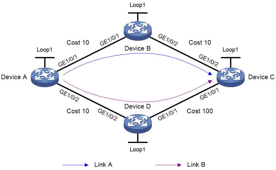
Table 3 Interface and IP address assignment
|
Device |
Interface |
IP address |
Device |
Interface |
IP address |
|
Device A |
Loop1 |
1::1/128 |
Device B |
Loop1 |
2::2/128 |
|
|
GE1/0/1 |
2000:1::1/64 |
|
GE1/0/1 |
2000:1::2/64 |
|
|
GE1/0/2 |
2000:4::1/64 |
|
GE1/0/2 |
2000:2::2/64 |
|
Device C |
Loop1 |
3::3/128 |
Device D |
Loop1 |
4::4/128 |
|
|
GE1/0/1 |
2000:3::3/64 |
|
GE1/0/1 |
2000:3::4/64 |
|
|
GE1/0/2 |
2000:2::3/64 |
|
GE1/0/2 |
2000:4::4/64 |
Procedure
1. Configure IPv6 addresses and prefixes for interfaces. (Details not shown.)
2. Configure Device A:
# Configure IPv6 IS-IS to achieve network level connectivity and set the IS-IS cost style to wide.
<DeviceA> system-view
[DeviceA] isis 1
[DeviceA-isis-1] network-entity 00.0000.0000.0001.00
[DeviceA-isis-1] cost-style wide
[DeviceA-isis-1] address-family ipv6
[DeviceA-isis-1-ipv6] quit
[DeviceA-isis-1] quit
[DeviceA] interface gigabitethernet 1/0/1
[DeviceA-GigabitEthernet1/0/1] isis ipv6 enable 1
[DeviceA-GigabitEthernet1/0/1] isis cost 10
[DeviceA-GigabitEthernet1/0/1] quit
[DeviceA] interface gigabitethernet 1/0/2
[DeviceA-GigabitEthernet1/0/2] isis ipv6 enable 1
[DeviceA-GigabitEthernet1/0/2] isis cost 10
[DeviceA-GigabitEthernet1/0/2] quit
[DeviceA] interface loopback 1
[DeviceA-LoopBack1] isis ipv6 enable 1
[DeviceA-LoopBack1] quit
# Enable SRv6 and configure a locator.
[DeviceA] segment-routing ipv6
[DeviceA-segment-routing-ipv6] locator aaa ipv6-prefix 11:: 64 static 32
[DeviceA-segment-routing-ipv6-locator-aaa] quit
[DeviceA-segment-routing-ipv6] quit
# Configure IPv6 IS-IS TI-LFA FRR.
[DeviceA] isis 1
[DeviceA-isis-1] address-family ipv6
[DeviceA-isis-1-ipv6] fast-reroute lfa
[DeviceA-isis-1-ipv6] fast-reroute ti-lfa
[DeviceA-isis-1-ipv6] quit
[DeviceA-isis-1] quit
# Apply the locator to the IPv6 IS-IS process.
[DeviceA] isis 1
[DeviceA-isis-1] address-family ipv6
[DeviceA-isis-1-ipv6] segment-routing ipv6 locator aaa
[DeviceA-isis-1-ipv6] quit
[DeviceA-isis-1] quit
3. Configure Device B:
# Configure IPv6 IS-IS to achieve network level connectivity and set the IS-IS cost style to wide.
<DeviceB> system-view
[DeviceB] isis 1
[DeviceB-isis-1] network-entity 00.0000.0000.0002.00
[DeviceB-isis-1] cost-style wide
[DeviceB-isis-1] address-family ipv6
[DeviceB-isis-1-ipv6] quit
[DeviceB-isis-1] quit
[DeviceB] interface gigabitethernet 1/0/1
[DeviceB-GigabitEthernet1/0/1] isis ipv6 enable 1
[DeviceB-GigabitEthernet1/0/1] isis cost 10
[DeviceB-GigabitEthernet1/0/1] quit
[DeviceB] interface gigabitethernet 1/0/2
[DeviceB-GigabitEthernet1/0/2] isis ipv6 enable 1
[DeviceB-GigabitEthernet1/0/2] isis cost 10
[DeviceB-GigabitEthernet1/0/2] quit
[DeviceB] interface loopback 1
[DeviceB-LoopBack1] isis ipv6 enable 1
[DeviceB-LoopBack1] quit
# Enable SRv6 and configure a locator.
[DeviceB] segment-routing ipv6
[DeviceB-segment-routing-ipv6] locator bbb ipv6-prefix 22:: 64 static 32
[DeviceB-segment-routing-ipv6-locator-bbb] quit
[DeviceB-segment-routing-ipv6] quit
# Configure IPv6 IS-IS TI-LFA FRR.
[DeviceB] isis 1
[DeviceB-isis-1] address-family ipv6
[DeviceB-isis-1-ipv6] fast-reroute lfa
[DeviceB-isis-1-ipv6] fast-reroute ti-lfa
# Apply the locator to the IPv6 IS-IS process.
[DeviceB-isis-1-ipv6] segment-routing ipv6 locator bbb
[DeviceB-isis-1-ipv6] quit
[DeviceB-isis-1] quit
4. Configure Device C:
# Configure IPv6 IS-IS to achieve network level connectivity and set the IS-IS cost style to wide.
<DeviceC> system-view
[DeviceC] isis 1
[DeviceC-isis-1] network-entity 00.0000.0000.0003.00
[DeviceC-isis-1] cost-style wide
[DeviceC-isis-1] address-family ipv6
[DeviceC-isis-1-ipv6] quit
[DeviceC-isis-1] quit
[DeviceC] interface gigabitethernet 1/0/1
[DeviceC-GigabitEthernet1/0/1] isis ipv6 enable 1
[DeviceC-GigabitEthernet1/0/1] isis cost 10
[DeviceC-GigabitEthernet1/0/1] quit
[DeviceC] interface gigabitethernet 1/0/2
[DeviceC-GigabitEthernet1/0/2] isis ipv6 enable 1
[DeviceC-GigabitEthernet1/0/2] isis cost 100
[DeviceC-GigabitEthernet1/0/2] quit
[DeviceC] interface loopback 1
[DeviceC-LoopBack1] isis ipv6 enable 1
[DeviceC-LoopBack1] quit
# Enable SRv6 and configure a locator.
[DeviceC] segment-routing ipv6
[DeviceC-segment-routing-ipv6] locator ccc ipv6-prefix 33:: 64 static 32
[DeviceC-segment-routing-ipv6-locator-ccc] quit
[DeviceC-segment-routing-ipv6] quit
# Configure IPv6 IS-IS TI-LFA FRR.
[DeviceC] isis 1
[DeviceC-isis-1] address-family ipv6
[DeviceC-isis-1-ipv6] fast-reroute lfa
[DeviceC-isis-1-ipv6] fast-reroute ti-lfa
# Apply the locator to the IPv6 IS-IS process.
[DeviceC-isis-1-ipv6] segment-routing ipv6 locator ccc
[DeviceC-isis-1-ipv6] quit
[DeviceC-isis-1] quit
5. Configure Device D:
# Configure IPv6 IS-IS to achieve network level connectivity and set the IS-IS cost style to wide.
<DeviceD> system-view
[DeviceD] isis 1
[DeviceD-isis-1] network-entity 00.0000.0000.0004.00
[DeviceD-isis-1] cost-style wide
[DeviceD-isis-1] address-family ipv6
[DeviceD-isis-1-ipv6] quit
[DeviceD-isis-1] quit
[DeviceD] interface gigabitethernet 1/0/1
[DeviceD-GigabitEthernet1/0/1] isis ipv6 enable 1
[DeviceD-GigabitEthernet1/0/1] isis cost 100
[DeviceD-GigabitEthernet1/0/1] quit
[DeviceD] interface gigabitethernet 1/0/2
[DeviceD-GigabitEthernet1/0/2] isis ipv6 enable 1
[DeviceD-GigabitEthernet1/0/2] isis cost 10
[DeviceD-GigabitEthernet1/0/2] quit
[DeviceD] interface loopback 1
[DeviceD-LoopBack1] isis ipv6 enable 1
[DeviceD-LoopBack1] quit
# Enable SRv6 and configure a locator.
[DeviceD] segment-routing ipv6
[DeviceD-segment-routing-ipv6] locator ddd ipv6-prefix 44:: 64 static 32
[DeviceD-segment-routing-ipv6-locator-ddd] quit
[DeviceD-segment-routing-ipv6] quit
# Configure IPv6 IS-IS TI-LFA FRR.
[DeviceD] isis 1
[DeviceD-isis-1] address-family ipv6
[DeviceD-isis-1-ipv6] fast-reroute lfa
[DeviceD-isis-1-ipv6] fast-reroute ti-lfa
# Apply the locator to the IPv6 IS-IS process.
[DeviceD-isis-1-ipv6] segment-routing ipv6 locator ddd
[DeviceD-isis-1-ipv6] quit
[DeviceD-isis-1] quit
Verifying the configuration
# Display IPv6 IS-IS routing information for 3::3/128.
[DeviceA] display isis route ipv6 3::3 128 verbose
Route information for IS-IS(1)
------------------------------
Level-1 IPv6 forwarding table
-----------------------------
IPv6 dest : 3::3/128
Flag : R/L/- Cost : 20
Admin tag : - Src count : 2
Nexthop : FE80::4449:7CFF:FEE0:206
Interface : GE1/0/1
TI-LFA:
Interface : GE1/0/2
BkNextHop : FE80::4449:91FF:FE42:407
LsIndex : 0x80000001
Backup label stack(top->bottom): {44::1:0:1}
Nib ID : 0x24000006
Flags: D-Direct, R-Added to Rib, L-Advertised in LSPs, U-Up/Down Bit Set
The output shows TI-LFA backup next hop information.
