- Table of Contents
- Related Documents
-
| Title | Size | Download |
|---|---|---|
| 03-SRv6 TE policy configuration | 343.69 KB |
Contents
Traffic steering to an SRv6 TE policy
SRv6 TE policy forwarding procedure
Restrictions: Hardware compatibility with SRv6-TE policy
SRv6 TE policy tasks at a glance
Configuring SRv6 TE policy attributes
Shutting down an SRv6 TE policy
Configuring BGP to advertise BGP IPv6 SR policy routes
Restrictions and guidelines for BGP IPv6 SR policy routes advertisement
Enabling BGP to advertise BGP IPv6 SR policy routes
Configuring BGP to redistribute BGP IPv6 SR policy routes
Enabling advertising BGP IPv6 SR policy routes to EBGP peers
Configuring BGP to control BGP IPv6 SR policy route selection and advertisement
Configuring SRv6 TE policy traffic steering
Configuring the SRv6 TE policy traffic steering mode
Configuring color-based traffic steering
Configuring tunnel policy-based traffic steering
Configuring DSCP-based traffic steering
Enabling SBFD for SRv6 TE policies
Configuring the BFD echo packet mode for SRv6 TE policies
Enabling hot standby for SRv6 TE policies
Configuring path switchover and deletion delays for SRv6 TE policies
Configuring the TTL processing mode of SRv6 TE policies
Configuring traffic forwarding statistics for SRv6 TE policies
Specifying the packet encapsulation type preferred in optimal route selection
Display and maintenance commands for SRv6 TE policies
SRv6 TE policy configuration examples
Example: Configuring SRv6 TE policy-based forwarding
Configuring SRv6 TE policies
About SRv6 TE policies
IPv6 Segment Routing Traffic Engineering (SRv6 TE) policies apply to scenarios where multiple paths exist between a source node and a destination node on an SRv6 network. The device can use an SRv6 TE policy to flexibly steer traffic to a proper forwarding path.
SRv6 TE policy identification
An SRv6 TE policy is identified by the following items:
· BSID—SID of the ingress node (source node).
· Color—Color attribute for the forwarding path. You can use the color attribute to distinguish an SRv6 TE policy from other SRv6 TE policies that are configured for the same source and destination nodes.
· Endpoint—IPv6 address of the destination node.
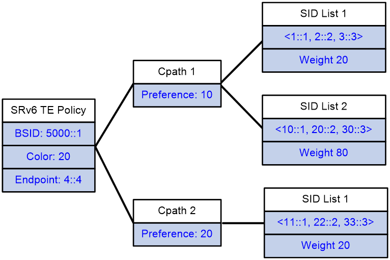
SRv6 TE policy contents
As show in Figure 1, an SRv6 TE policy consists of candidate paths with different preferences. Each candidate path can have one or multiple subpaths identified by segment lists (also called SID lists).
· Candidate path
An SRv6 TE policy can have multiple candidate paths. Candidate paths are uniquely identified by their preference values. An SRv6 TE policy chooses a candidate path from all its candidate paths based on the preference values to forward traffic.
Two SRv6 TE policies cannot share the same candidate path.
· SID list
A SID list is a list of SIDs that indicates a packet forwarding path. Each SID is the IPv6 address of a node on the forwarding path.
A candidate path can have a single SID list or multiple SID lists that use different weight values. After an SRv6 TE policy chooses a candidate path with multiple SID lists, the traffic will be load shared among the SID lists based on weight values.
Figure 1 SRv6 TE policy contents
SRv6 TE policy creation
An SRv6 TE policy can be created in the following modes:
· Manual configuration from CLI
In this method, you need to manually configure the candidate settings for the SRv6 TE policy, such as candidate path preferences, SID lists and weights.
· Learning from an BGP IPv6 SR policy route
To support SRv6 TE policy, MP-BGP defines the BGP IPv6 SR address family and the SRv6 TE policy Network Layer Reachability Information (NLRI). The SRv6 TE policy NLRI is called the BGP IPv6 SR policy route (or BGP IPv6 SR policy). An BGP IPv6 SR policy route contains SRv6 TE policy settings, including the BSID, color, endpoint, candidate preferences, SID lists, and SID list weights.
The device can advertise its local SRv6 TE policy settings to its BGP IPv6 SR policy peer through an BGP IPv6 SR policy route. The peer device can create an SRv6 TE policy according to the received SRv6 TE policy settings.
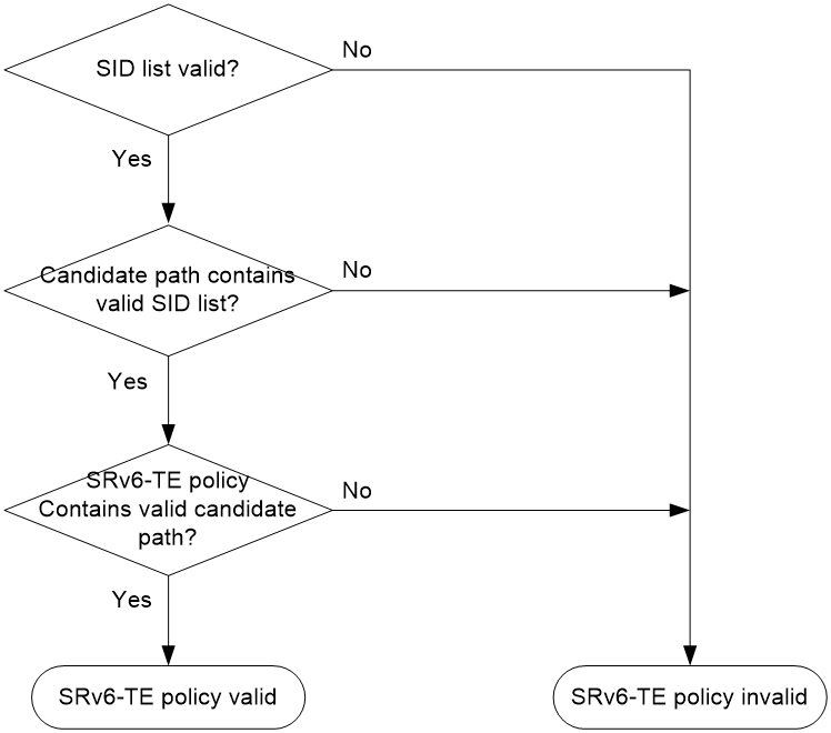
SRv6 TE policy validity
An SRv6 TE policy must be valid in order to ensure successful traffic forwarding.
The following describes the rules for identifying the validity of an SRv6 TE policy:
1. An SRv6 TE policy is valid only if it has valid candidate paths.
2. A candidate path is valid only if it has a valid SID list.
3. A SID list is valid if none of the following situations exists:
¡ The SID list is empty.
¡ The weight of the SID list is 0.
¡ An SR node and the first IPv6 address in the SID list cannot reach each other.
Figure 2 SRv6 TE policy validity determination
Traffic steering to an SRv6 TE policy
The following modes are available to steer traffic to an SRv6 TE policy:
· BSID—If the destination IPv6 address of a received packet is the BSID of an SRv6 TE policy, the device uses the SRv6 TE policy to forward the packet.
· Color—The device searches for an SRv6 TE policy that has the same color and endpoint address as the color and nexthop address of a BGP route. If a matching SRv6 TE policy exists, the device recurse the BGP route to that SRv6 TE policy. Then, when the device receives packets that match the BGP route, it forwards the packets through the SRv6 TE policy.
· Tunnel policy—In an MPLS L3VPN, EVPN L3VPN, EVPN VPLS, or EVPN VPWS network, use an SRv6 TE policy as the public tunnel to carry the packets of a VPN instance. For more information about the tunnel policy configuration, see MPLS Configuration Guide.
· DSCP—Create color-to-DSCP mappings for an SRv6 TE policy group, and create a tunnel policy that binds a destination IP address to the SRv6 TE policy group. Upon receiving a packet with the specified destination address, the device searches for the SRv6 TE policy containing the color value mapped to the DSCP value of the packet. The device will use the SRv6 TE policy to forward the packet.
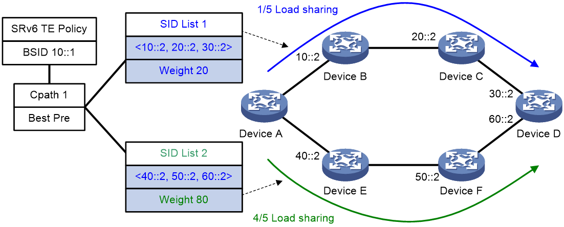
SRv6 TE policy path selection
After traffic is steered in to an SRv6 TE policy, the SRv6 TE policy selects a forwarding path for the traffic as follows:
1. Selects the valid candidate path that has the highest preference.
2. Performs Weighted ECMP (WECMP) load sharing among the SID lists of the selected candidate path. The load of SID list x is equal to Weight x/(Weight 1 + Weight 2 + … + Weight n).
For example, as shown in Figure 3, Device A first selects a valid SRv6 TE policy by BSID. Then, the device selects a candidate path by preference. The candidate path has two valid SID lists: SID list 1 and SID list 2. The weight value of SID list 1 is 20 and the weight value of SID list 2 is 80. One fifth of the traffic will be forwarded through the subpath identified by SID list 1. Four fifth of the traffic will be forwarded through the subpath identified by SID list 2.
Figure 3 SRv6 TE policy path selection
SRv6 TE policy forwarding procedure
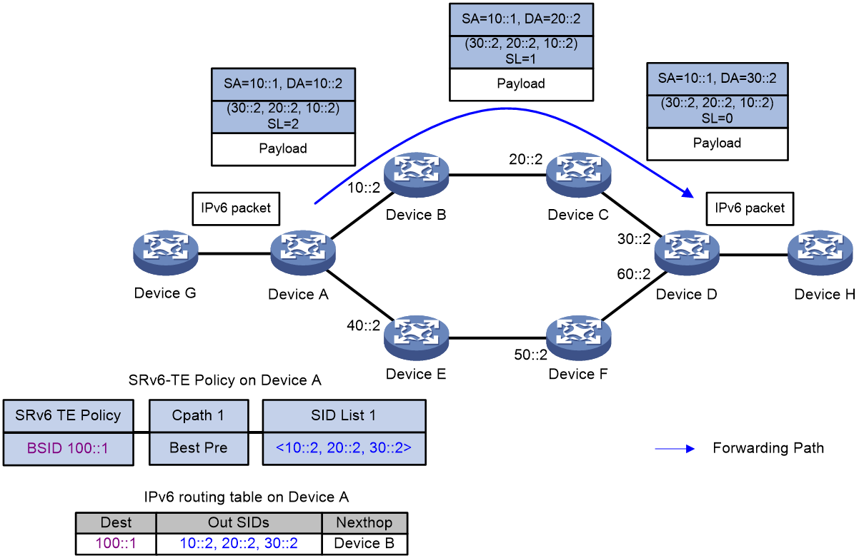
As shown in Figure 4, the SRv6 TE policy forwarding procedure is as follows (BSID-based traffic steering as an example):
1. After Device A receives a packet with destination address 100::1, it searches its IPv6 routing table and determines that the address is a BSID. Then, Device A encapsulates the packet with an SRH header according to the SRv6 TE policy of the BSID. The SRH header contains SID list {10::2, 20::2, 30::2}, where 10::2 is the SID for Device B, 20::2 is the SID for Device C, and 30::2 is the SID for Device D.
2. Device A forward the packet to the next hop Device B.
3. After Device B receives the packet, it obtains the next hop Device C from the SRH, and then forwards the packet to Device C.
4. After Device C receives the packet, it obtains the next hop Device D from the SRH, and then forwards the packet to Device D.
5. After Device D receives the packet, it identifies that the SL value is 0 in the SRH. So Device D decapsulates the packet. Device D deletes the SRH header and forwards the packet according to the destination address of the packet.
Figure 4 SRv6 TE policy forwarding diagram
SBFD for SRv6 TE policy
An SRv6 TE policy cannot maintain its status by exchanging messages between devices. You can configure seamless BFD (SBFD) to verify the connectivity of an SRv6 TE policy to implement fast failover in milliseconds.
As shown in Figure 5, configure an SRv6 TE policy on Device A and use SBFD to detect the SRv6 TE policy. The detection process is as follows:
1. The source node (Device A, the initiator) and sends SBFD packets that encapsulate the SID lists of the primary and backup candidate paths of the SRv6 TE policy.
2. After the destination node (Device E, the reflector) receives an SBFD packets, it checks whether the remote discriminator carried the packet is the same as the local discriminator. If yes, the reflector sends the SBFD response packet to the initiator by using the IPv6 routing table. If no, the reflector drops the SBFD packet.
3. If the source node can receive the SBFD response within the detection timeout time, it determines the corresponding SID list (forwarding path) of the SRv6 TE policy is available. If no response is received, the device determines that the SID list is faulty. If all the SID lists for the primary path are faulty, SBFD triggers a primary-to-back path switchover.
Figure 5 SBFD for SRv6 TE policy procedure
|
|
NOTE: Because SBFD responses are forwarded according to the IPv6 routing table lookup, all SBFD sessions for the SRv6 TE policies that have the same source and destination nodes use the same path to send responses. A failure of the SBFD response path will cause all the SBFD sessions to be down and consequentially traffic cannot be forwarded through the SRv6 TE policies. |
SRv6 TE policy hot standby
If an SRv6 TE policy has multiple valid candidate paths, the device chooses the candidate path with the greatest preference value. If the chosen path fails, the SRv6 TE policy must select another candidate path. During path reselection, packet loss might occur and thus affect service continuity.
The SRv6 TE hot standby feature can address this issue. This feature takes the candidate path with the greatest preference value as the primary path and that with the second greatest preference value as the backup path in hot standby state. As shown in Figure 6, when the forwarding paths corresponding to all SID lists of the primary path fails, the standby path immediately takes over to minimize service interruption.
Figure 6 SRv6 TE policy hot standby
You can configure both the hot standby and SBFD features for an SR-TE policy. Use SBFD to detect the availability of the primary and standby paths specified for hot standby. If all SID lists of the primary path become unavailable, the standby path takes over and a path recalculation is performed. The standby path becomes the new primary path, and a new standby path is selected. If both the primary and standby paths fail, the SR-TE policy will calculate new primary and standby paths.
Restrictions: Hardware compatibility with SRv6-TE policy
|
Hardware |
SRv6-TE policy compatibility |
|
MSR810, MSR810-W, MSR810-W-DB, MSR810-LM, MSR810-W-LM, MSR810-10-PoE, MSR810-LM-HK, MSR810-W-LM-HK, MSR810-LM-CNDE-SJK, MSR810-CNDE-SJK |
Yes |
|
MSR810-LMS, MSR810-LUS |
No |
|
MSR810-LMS-EA, MSR810-LME |
Yes |
|
MSR1004S-5G |
Yes |
|
MSR2600-6-X1, MSR2600-10-X1, MSR2600-15-X1 |
Yes |
|
MSR 2630 |
Yes |
|
MSR3600-28, MSR3600-51 |
Yes |
|
MSR3600-28-SI, MSR3600-51-SI |
No |
|
MSR3600-28-X1, MSR3600-28-X1-DP, MSR3600-51-X1, MSR3600-51-X1-DP |
Yes |
|
MSR3610-I-DP, MSR3610-IE-DP, MSR3610-IE-ES, MSR3610-IE-EAD, MSR-EAD-AK770, MSR3610-I-IG, MSR3610-IE-IG |
Yes |
|
MSR3610-X1, MSR3610-X1-DP, MSR3610-X1-DC, MSR3610-X1-DP-DC, MSR3620-X1, MSR3640-X1 |
Yes |
|
MSR3610, MSR3620, MSR3620-DP, MSR3640, MSR3660 |
Yes |
|
MSR3610-G, MSR3620-G |
Yes |
|
MSR3640-X1-HI |
Yes |
|
Hardware |
SRv6-TE policy compatibility |
|
MSR810-W-WiNet, MSR810-LM-WiNet |
Yes |
|
MSR830-4LM-WiNet |
Yes |
|
MSR830-5BEI-WiNet, MSR830-6EI-WiNet, MSR830-10BEI-WiNet |
Yes |
|
MSR830-6BHI-WiNet, MSR830-10BHI-WiNet |
Yes |
|
MSR2600-6-WiNet, MSR2600-10-X1-WiNet |
Yes |
|
MSR2630-WiNet |
Yes |
|
MSR3600-28-WiNet |
Yes |
|
MSR3610-X1-WiNet |
Yes |
|
MSR3610-WiNet, MSR3620-10-WiNet, MSR3620-DP-WiNet, MSR3620-WiNet, MSR3660-WiNet |
Yes |
|
Hardware |
SRv6-TE policy compatibility |
|
MSR2630-XS |
Yes |
|
MSR3600-28-XS |
Yes |
|
MSR3610-XS |
Yes |
|
MSR3620-XS |
Yes |
|
MSR3610-I-XS |
Yes |
|
MSR3610-IE-XS |
Yes |
|
MSR3620-X1-XS |
Yes |
|
MSR3640-XS |
Yes |
|
MSR3660-XS |
Yes |
|
Hardware |
SRv6-TE policy compatibility |
|
MSR810-LM-GL |
Yes |
|
MSR810-W-LM-GL |
Yes |
|
MSR830-6EI-GL |
Yes |
|
MSR830-10EI-GL |
Yes |
|
MSR830-6HI-GL |
Yes |
|
MSR830-10HI-GL |
Yes |
|
MSR1004S-5G-GL |
Yes |
|
MSR2600-6-X1-GL |
Yes |
|
MSR3600-28-SI-GL |
No |
SRv6 TE policy tasks at a glance
To configure an SRv6 TE policy, perform the following tasks:
1. Configuring IGP-based SID advertisement
Perform this task on each SRv6 node. For more information, see "Configuring IPv6 Segment Routing."
3. Configuring an SRv6 TE policy
b. Configuring SRv6 TE policy attributes
c. (Optional.) Shutting down an SRv6 TE policy
d. Configuring a candidate path
4. (Optional.) Configuring BGP to advertise BGP IPv6 SR policy routes
a. Enabling BGP to advertise BGP IPv6 SR policy routes
b. Configuring BGP to redistribute BGP IPv6 SR policy routes
c. (Optional.) Enabling advertising BGP IPv6 SR policy routes to EBGP peers
d. (Optional.) Enabling Router ID filtering
e. (Optional.) Configuring BGP to control BGP IPv6 SR policy route selection and advertisement
f. (Optional.) Maintaining BGP sessions
5. Configuring SRv6 TE policy traffic steering
6. (Optional.) Configuring high availability features for SRv6 TE policy
¡ Enabling SBFD for SRv6 TE policies
¡ Configuring the BFD echo packet mode for SRv6 TE policies
¡ Enabling hot standby for SRv6 TE policies
¡ Configuring path switchover and deletion delays for SRv6 TE policies
7. (Optional.) Configuring the TTL processing mode of SRv6 TE policies
8. (Optional.) Configuring traffic forwarding statistics for SRv6 TE policies
9. (Optional.) Specifying the packet encapsulation type preferred in optimal route selection
Configuring a SID list
About this task
After you add nodes to a SID list, the system will sort the nodes in ascending order of node index. The node with the smallest index represents the next hop of the source node on the forwarding path.
Procedure
1. Enter system view.
system-view
2. Enable SRv6 and enter SRv6 view.
segment-routing ipv6
By default, SRv6 is disabled.
3. Create and enter the SRv6 TE view.
traffic-engineering
4. Create a SID list and enter its view.
segment-list segment-list-name
5. Add a node to the SID list.
index index-number ipv6 ipv6-address
Creating an SRv6 TE policy
1. Enter system view.
system-view
2. Enter SRv6 view.
segment-routing ipv6
3. Enter SRv6 TE view.
traffic-engineering
4. Create an SRv6 TE policy and enter its view.
policy policy-name
Configuring SRv6 TE policy attributes
About this task
An SRv6 TE policy is identified by the following items: BSID, color, and endpoint.
You can bind a BSID to the policy manually, or set only the color and endpoint attributes of the policy so the system automatically assigns a BSID to the policy. If you use both methods, the manually bound BSID takes effect.
Restrictions and guidelines
The configured BSID must be on the locator specified for SRv6 TE policies in SRv6 TE view. Otherwise, the SRv6 TE policy cannot forward packets. For more information about the locator configuration, see "Configuring IPv6 Segment Routing."
Different SRv6 TE policies cannot have the same color or endpoint IP address.
Procedure
1. Enter system view.
system-view
2. Enter SRv6 view.
segment-routing ipv6
3. Enter SRv6 TE view.
traffic-engineering
4. Specify a locator for SRv6 TE.
srv6-policy locator locator-name
By default, no locator is specified for SRv6 TE.
5. Enter SRv6 TE policy view.
policy policy-name
6. Configure a BSID for the policy.
binding-sid ipv6 ipv6-address
7. Set the color and endpoint attributes.
color color-value end-point ipv6 ipv6-address
By default, the color and endpoint attributes of an SRv6 TE policy are not configured.
Shutting down an SRv6 TE policy
About this task
This feature controls the administrative state of an SRv6 TE policy.
If multiple SRv6 TE policies exist on the device, you can shut down unnecessary SRv6 TE policies to prevent them from affecting traffic forwarding.
Procedure
1. Enter system view.
system-view
2. Enter SRv6 view.
segment-routing ipv6
3. Enter SRv6 TE view.
traffic-engineering
4. Enter SRv6 TE policy view.
policy policy-name
5. Shut down the SRv6 TE policy.
shutdown
By default, an SRv6 TE policy is not administratively shut down.
Configuring a candidate path
1. Enter system view.
system-view
2. Enter SRv6 view.
segment-routing ipv6
3. Enter SRv6 TE view.
traffic-engineering
4. Enter SRv6 TE policy view.
policy policy-name
5. Create and enter SRv6 TE policy candidate path view.
candidate-paths
6. Set the preference for a candidate path and enter SRv6 TE policy path preference view.
preference preference-value
By default, no candidate path preferences are set.
Each preference represents a candidate path.
7. Specify an explicit path for the candidate path.
explicit segment-list segment-list-name [ weight weight-value ]
A candidate path can have multiple SID lists.
Configuring BGP to advertise BGP IPv6 SR policy routes
Restrictions and guidelines for BGP IPv6 SR policy routes advertisement
For more information about BGP commands, see Layer 3—IP Routing Commands.
Enabling BGP to advertise BGP IPv6 SR policy routes
1. Enter system view.
system-view
2. Configure a global router ID.
router id router-id
By default, no global router ID is configured.
3. Enable a BGP instance and enter its view.
bgp as-number [ instance instance-name ]
By default, BGP is disabled and no BGP instances exist.
4. Configure a peer or peer group.
peer { group-name | ipv6-address [ prefix-length ] } as-number as-number
5. Create the BGP IPv6 SR policy address family and enter its view.
address-family ipv6 sr-policy
6. Enable BGP to exchange SRv6 TE policy routing information with the peer or peer group.
peer { group-name | ipv6-address [ prefix-length ] } enable
By default, the device cannot use BGP to exchange SRv6 TE policy routing information with a peer or peer group.
Configuring BGP to redistribute BGP IPv6 SR policy routes
About this task
After you configure BGP to redistribute BGP IPv6 SR policy routes, the system will redistribute the local BGP IPv6 SR policy routes to the BGP routing table and advertise the routes to peers. Then, the peers can forward traffic based on the SRv6 TE policy.
Procedure
1. Enter system view.
system-view
2. Enter BGP instance view.
bgp as-number [ instance instance-name ]
3. Enter BGP IPv6 SR policy address family view.
address-family ipv6 sr-policy
4. Enable BGP to redistribute routes from SRv6 TE policies.
import-route sr-policy
By default, BGP does not redistribute BGP IPv6 SR policy routes.
Enabling advertising BGP IPv6 SR policy routes to EBGP peers
About this task
By default, BGP IPv6 SR policy routes are advertised among IBGP peers. To advertise BGP IPv6 SR policy routes to EBGP peers, you must perform this task to enable the advertisement capability.
Procedure
1. Enter system view.
system-view
2. Enter BGP instance view.
bgp as-number [ instance instance-name ]
3. Enter BGP IPv6 SR policy address family view.
address-family ipv6 sr-policy
4. Enable advertising BGP IPv6 SR policy routes to EBGP peers.
advertise ebgp enable
By default, BGP IPv6 SR policy routes are not advertised to EBGP peers.
Enabling Router ID filtering
About this task
For the device to process only part of the received BGP IPv6 SR policy routes, you can perform this task to enable filtering the routes by Router ID.
This feature enables the device to check the Route Target attribute of a received BGP IPv6 SR policy route. The device accepts the route only if the Route Target attribute contains the Router ID of the local device.
Restrictions and guidelines
To use Router ID filtering, make sure you add Route Target attributes to BGP IPv6 SR policy routes properly by using routing policy or other methods. Otherwise, Router ID filtering might learn or drop BGP IPv6 SR policy routes incorrectly.
Procedure
1. Enter system view.
system-view
2. Enter BGP instance view.
bgp as-number [ instance instance-name ]
3. Enter BGP IPv6 SR policy address family view.
address-family ipv6 sr-policy
4. Enable Router ID filtering.
router-id filter
By default, Router ID filtering is disabled.
Configuring BGP to control BGP IPv6 SR policy route selection and advertisement
1. Enter system view.
system-view
2. Enter BGP instance view.
bgp as-number [ instance instance-name ]
3. Enter BGP IPv6 SR policy address family view.
address-family ipv6 sr-policy
4. Specify the local router as the next hop for routes sent to a peer or peer group.
peer { group-name | ipv6-address [ prefix-length ] } next-hop-local
By default, BGP sets the local router as the next hop for all routes sent to an EBGP peer or peer group. BGP does not set the local router as the next hop for routes sent to an IBGP peer or peer group.
5. Allow a local AS number to exist in the AS_PATH attribute of routes from a peer or peer group, and to set the number of times the local AS number can appear.
peer { group-name | ipv6-address [ prefix-length ] } allow-as-loop [ number ]
By default, the local AS number is not allowed to exist in the AS_PATH attribute of routes from a peer or peer group.
6. Specify a preferred value for routes received from a peer or peer group.
peer { group-name | ipv6-address [ prefix-length ] } preferred-value value
By default, the preferred value is 0 for routes received from a peer or peer group.
7. Set the maximum number of routes that can be received from a peer or peer group.
peer { group-name | ipv6-address [ prefix-length ] } route-limit prefix-number [ { alert-only | discard | reconnect reconnect-time } | percentage-value ] *
By default, the number of routes that can be received from a peer or peer group is not limited.
8. Configure the device as a route reflector and specify a peer or peer group as a client.
peer { group-name | ipv6-address [ prefix-length ] } reflect-client
By default, neither the route reflector nor the client is configured.
9. Specify an IPv6 prefix list to filter routes received from or advertised to a peer or peer group.
peer { group-name | ipv6-address [ prefix-length ] } prefix-list ipv6-prefix-list-name { export | import }
By default, no prefix list based filtering is configured.
10. Apply a routing policy to routes incoming from or outgoing to a peer or peer group.
peer { group-name | ipv6-address [ prefix-length ] } route-policy route-policy-name { export | import }
By default, no routing policy is applied to routes incoming from or outgoing to a peer or peer group.
11. Advertise the COMMUNITY attribute to a peer or peer group.
peer { group-name | ipv6-address [ prefix-length ] } advertise-community
By default, no COMMUNITY attribute is advertised to any peers or peer groups.
12. Advertise the extended community attribute to a peer or peer group.
peer { group-name | ipv6-address [ prefix-length ] } advertise-ext-community
By default, no extended community attribute is advertised to any peers or peer groups.
13. Assign a peer or peer group a high priority in BGP route selection.
peer { group-name | ipv6-address [ prefix-length ] } high-priority
By default, a peer or peer group does not have a high priority in BGP route selection.
Maintaining BGP sessions
To maintain BGP sessions, execute the following commands in user view:
· Reset BGP sessions for the BGP IPv6 SR policy address family.
reset bgp [ instance instance-name ] { as-number | ipv6-address [ prefix-length ] | all | external | group group-name | internal } ipv6 sr-policy
· Soft-reset BGP sessions for the BGP IPv6 SR policy address family.
refresh bgp [ instance instance-name ] { ipv6-address [ prefix-length ] | all | external | group group-name | internal } { export | import } ipv6 sr-policy
Configuring SRv6 TE policy traffic steering
Configuring the SRv6 TE policy traffic steering mode
Restrictions and guidelines
This feature does not take effect on L2VPN networks.
Prerequisites
To use color-based traffic steering, you need to add the color extended community to IPv6 unicast routes by using routing policy or other methods. For information about the routing policy configuration, see Layer 3—IP Routing Configuration Guide.
To use tunnel policy-based traffic steering, you need to configure a bound tunnel, preferred tunnel, or load sharing tunnel policy that uses an SRv6 TE policy. For more information about the tunnel policy configuration, see MPLS Configuration Guide.
Procedure
1. Enter system view.
system-view
2. Enter BGP instance view.
bgp as-number [ instance instance-name ]
3. Configure the traffic steering mode for SRv6 TE policies.
sr-policy steering { disable | policy-based }
By default, the device steering data packets to SRv6 TE policies based on colors of the packets.
If you specify the policy-based keyword, the device steers traffic to an SRv6 TE policy based on the bound policy, color, and load sharing tunnel policy in a descending order of priority.
Configuring color-based traffic steering
1. Enter system view.
system-view
2. Enter routing policy node view.
route-policy route-policy-name { deny | permit } node node-number
3. Set the color extended community attribute for BGP routes.
apply extcommunity color color [ additive ]
By default, no color extended community attribute is set for BGP routes.
4. Return to system view.
quit
5. Enter BGP instance view.
bgp as-number [ instance instance-name ]
6. Enter a BGP address family view as needed:
¡ Enter BGP IPv4 unicast address family view.
address-family ipv4 [ unicast ]
¡ Enter BGP IPv6 unicast address family view
address-family ipv6 [ unicast ]
¡ Enter BGP VPNv4 address family view.
address-family vpnv4
¡ Enter BGP VPNv6 address family view.
address-family vpnv6
¡ Enter BGP EVPN address family view.
address-family l2vpn evpn
7. Apply the routing policy to filter routes advertised to or received from a peer or peer group.
peer { group-name | ipv6-address [ prefix-length ] } route-policy route-policy-name { export | import }
By default, no routing policy is applied to a peer or peer group.
Configuring tunnel policy-based traffic steering
Configuring a tunnel policy
1. Enter system view.
system-view
2. Create a tunnel policy and enter tunnel policy view.
tunnel-policy tunnel-policy-name [ default ]
3. Configure the tunnel policy. Choose the following tasks as needed:
¡ Specify an SRv6 TE policy to be bound with the specified destination IPv6 address.
binding-destination dest-ipv6-address srv6-policy { name policy-name | end-point ipv6 ipv6-address color color-value } [ ignore-destination-check ] [ down-switch ]
By default, no SRv6 TE policy is specified for a tunnel policy.
¡ Specify an SRv6 TE policy as a preferred tunnel of the tunnel policy.
preferred-path srv6-policy name sr-policy-name
By default, no preferred tunnel is specified for a tunnel policy.
¡ Configuring SRv6 TE policy load sharing for the tunnel policy.
select-seq srv6-policy load-balance-number number
By default, no load sharing tunnel policy is configured.
For more information about the tunnel policy commands, see MPLS Command Reference.
Specifying the tunnel policy for a VPN instance
1. Enter system view.
system-view
2. Enter a VPN instance view as needed.
¡ Enter VPN instance view.
ip vpn-instance vpn-instance-name
¡ Execute the following commands in sequence to enter VPN instance IPv4 address family view:
ip vpn-instance vpn-instance-name
address-family ipv4
¡ Execute the following commands in sequence to enter VPN instance IPv6 address family view:
ip vpn-instance vpn-instance-name
address-family ipv6
3. Specify a tunnel policy for the VPN instance.
tnl-policy tunnel-policy-name
By default, no tunnel policy is specified for a VPN instance.
For more information about this command, see MPLS L3VPN commands in MPLS Command Reference.
Configuring DSCP-based traffic steering
About this task
Each SRv6 TE policy in an SRv6 TE policy group has a different color attribute value. By configuring color-to-DSCP mappings for an SRv6 TE policy group, you associate DSCP values to SRv6 TE policies. This allows IPv6 packets containing a specific DSCP value to be steered to the corresponding SRv6 TE policy for further forwarding.
Restrictions and guidelines
You can map the color values of only valid SRv6 TE policies to DSCP values.
You can configure color-to-DSCP mappings separately for the IPv4 address family and IPv6 address family. For a specific address family, a DSCP value can be mapped to only one color value.
Use the color match dscp default command to specify the default SRv6 TE policy for an address family. If no SRv6 TE policy in an SRv6 TE policy group matches a specific DSCP value, the default SRv6 TE policy is used to forward packets containing the DSCP value. Only one default SRv6 TE policy can be specified for an address family.
When the device receives an IPv4 or IPv6 packet that does not match any color-to-DSCP mapping, the device selects a valid SRv6 TE policy for the packet in the following order:
1. The default SRv6 TE policy specified for the same address family as the packet.
2. The default SRv6 TE policy specified for the other address family.
3. The SRv6 TE policy mapped to the smallest DSCP value in the same address family as the packet.
4. The SRv6 TE policy mapped to the smallest DSCP value in the other address family.
Procedure
1. Enter system view.
system-view
2. Enter SRv6 view.
segment-routing ipv6
3. Enter SRv6 TE view.
traffic-engineering
4. Create an SRv6 TE policy group and enter its view.
policy-group group-id
5. Configure the endpoint IPv6 address for the SRv6 TE policy group.
end-point ipv6 ipv6-address
By default, no endpoint IPv6 address is configured for the SRv6 TE policy group.
The SRv6 TE policy corresponding to each color value in the SRv6 TE policy group must use the same endpoint IPv6 address as the SRv6 TE policy group.
6. Create color-to-DSCP mappings for the SRv6 TE policy group.
color color-value match dscp { ipv4 | ipv6 } dscp-value-list
color color-value match dscp { ipv4 | ipv6 } default
By default, no color-to-DSCP mappings are created for the SRv6 TE policy group.
DSCP-based traffic steering cannot function if no color-to-DSCP mappings are created.
7. Return to system view.
quit
8. Create a tunnel policy and enter tunnel policy view.
tunnel-policy tunnel-policy-name [ default ]
9. Bind the SRv6 TE policy group to a destination IP address.
binding-destination dest-ip-address sr-policy group sr-policy-group-id [ ignore-destination-check ] [ down-switch ]
By default, a tunnel policy does not bind any SRv6 TE policy group to a destination IP address.
For more information about the command, see tunnel policy commands in MPLS Command Reference.
Enabling SBFD for SRv6 TE policies
Restrictions and guidelines
You can enable SBFD for all SRv6 TE policies globally in SRv6 TE view or for a specific SRv6 TE policy in SRv6 TE policy view. The policy-specific configuration takes precedence over the global configuration. An SRv6 TE policy uses the global configuration only when it has no policy-specific configuration.
The remote discriminator specified in this command must be the same as that specified in the sbfd local-discriminator command on the reflector. Otherwise, the reflector will not send responses to the initiator.
The device supports the echo packet mode BFD and the SBFD for an SRv6 TE policy. If both modes are configured for the same SRv6 TE policy, the SBFD takes effect.
Procedure
1. Enter system view.
system-view
2. Configure the source IPv6 address used by the initiator to send SBFD packets.
sbfd source-ipv6 ipv6-address
By default, no source IPv6 address is configured for SBFD packets.
3. Enter SRv6 view.
segment-routing ipv6
4. Enter SRv6 TE view.
traffic-engineering
5. Enable SBFD for all SRv6 TE policies and configure the SBFD session parameters.
srv6-policy sbfd remote remote-id [ template template-name ] [ backup-template backup-template-name ]
By default, SBFD is disabled for all SRv6 TE policies.
6. Enter SRv6 TE policy view.
policy policy-name
7. Configure SBFD for the SRv6 TE policy.
sbfd { disable | enable [ remote remote-id ] [ template template-name ] [ backup-template backup-template-name ] [ oam-sid sid ] }
By default, SBFD is not configured for an SRv6 TE policy.
Configuring the BFD echo packet mode for SRv6 TE policies
Restrctions and guidelines
You can configure the echo packet mode BFD for all SRv6 TE policies globally in SRv6 TE view or for a specific SRv6 TE policy in SRv6 TE policy view. The policy-specific configuration takes precedence over the global configuration. An SRv6 TE policy uses the global configuration only when it has no policy-specific configuration.
The device supports the echo packet mode BFD and the SBFD for an SRv6 TE policy. If both modes are configured for the same SRv6 TE policy, the SBFD takes effect.
Procedure
1. Enter system view.
system-view
2. Enter SRv6 view.
segment-routing ipv6
3. Enter SRv6 TE view.
traffic-engineering
4. Enable echo packet mode BFD for all SRv6 TE policies and configure the BFD session parameters.
srv6-policy bfd echo source-ipv6 ipv6-address [ template template-name ] [ backup-template backup-template-name ]
By default, the echo packet mode BFD is disabled for all SRv6 TE policies.
5. Enter SRv6 TE policy view.
policy policy-name
6. Configure the echo packet mode BFD for the SRv6 TE policy.
bfd echo { disable | enable [ source-ipv6 ipv6-address ] [ template template-name ] [ backup-template backup-template-name ] [ oam-sid sid ] }
By default, the echo packet mode BFD is not configured for an SRv6 TE policy. An SRv6 TE policy uses the echo BFD settings configured in SRv6 TE view.
Enabling hot standby for SRv6 TE policies
Restrictions and guidelines
You can enable hot standby for all SRv6 TE policies globally in SRv6 TE view or for a specific SRv6 TE policy in SRv6 TE policy view. The policy-specific configuration takes precedence over the global configuration. An SRv6 TE policy uses the global configuration only when it has no policy-specific configuration.
Procedure
1. Enter system view.
system-view
2. Enter SRv6 view.
segment-routing ipv6
3. Enter SRv6 TE view.
traffic-engineering
4. Enable hot standby for all SRv6 TE policies.
srv6-policy backup hot-standby enable
By default, hot standby is disabled for all SRv6 TE policies.
5. Enter SRv6 TE policy view.
policy policy-name
6. Configure hot standby for the SRv6 TE policy.
backup hot-standby { disable | enable }
By default, hot standby is not configured for an SRv6 TE policy, and the hot standby configuration in SRv6 TE view applies.
Configuring path switchover and deletion delays for SRv6 TE policies
About this task
The switchover delay and deletion delay mechanism is used to avoid traffic forwarding failure during a forwarding path (SID list) switchover.
When updating an SRv6 TE policy forwarding path, the device first establishes the new forwarding path before it deletes the old one. During the new path setup process, the device uses the old path to forward traffic until the switchover delay timer expires. When the switchover delay timer expires, the device switches traffic to the new path. The old path is deleted when the deletion delay timer expires.
Procedure
1. Enter system view.
system-view
2. Enter SRv6 view.
segment-routing ipv6
3. Enter SRv6 TE view.
traffic-engineering
4. Configure the switchover delay time and deletion delay time for the SRv6 TE policy forwarding path.
srv6-policy switch-delay switch-delay-time delete-delay delete-delay-time
By default, the switchover delay time and deletion delay time for the SRv6 TE policy forwarding path is 5000 milliseconds and 20000 milliseconds, respectively.
Configuring the TTL processing mode of SRv6 TE policies
About this task
An SRv6 TE policy used as a public tunnel supports the following TTL processing modes:
· Uniform—When the ingress node adds a new IPv6 header to an IP packet, it copies the TTL value of the original IP packet to the Hop Limit field of the new IPv6 header. Each node on the SRv6 TE policy forwarding path decreases the Hop Limit value in the new IPv6 header by 1. The node that de-encapsulates the packet copies the remaining Hop Limit value back to the original IP packet when it removes the new IPv6 header. The TTL value can reflect how many hops the packet has traversed in the public network. The tracert facility can show the real path along which the packet has traveled.
· Pipe—When the ingress node adds a new IPv6 header to an IP packet, it does not copy the TTL value of the original IP packet to the Hop Limit field of the new IPv6 header. It sets the Hop Limit value in the new IPv6 header to 255. Each node on the SRv6 TE policy forwarding path decreases the Hop Limit value in the new IPv6 header by 1. The node that de-encapsulates the packet does not change the IPv6 TTL value according to the remaining Hop Limit value in the new IPv6 header. Therefore, the public network nodes are invisible to user networks, and the tracert facility cannot show the real path in the public network.
Procedure
1. Enter system view.
system-view
2. Enter SRv6 view.
segment-routing ipv6
3. Configure the TTL processing mode of SRv6 TE policies.
ttl-mode { pipe | uniform }
By default, the TTL processing mode of SRv6 TE policies is pipe.
Configuring traffic forwarding statistics for SRv6 TE policies
About this task
This feature collects statistics on the traffic forwarded by SRv6 TE policies.
Restrictions and guidelines
You can configure traffic forwarding statistics for all SRv6 TE policies globally in SRv6 TE view or for a specific SRv6 TE policy in SRv6 TE policy view. The policy-specific configuration takes precedence over the global configuration. An SRv6 TE policy uses the global configuration only when it has no policy-specific configuration.
Procedure
1. Enter system view.
system-view
2. Enter SRv6 view.
segment-routing ipv6
3. Enter SRv6 TE view.
traffic-engineering
4. Enable traffic forwarding statistics for all SRv6 TE policies.
srv6-policy forwarding statistics [ service-class ] enable
By default, traffic forwarding statistics is disabled for all SRv6 TE policies.
If you specify the service-class keyword, in addition to statistics of total traffic forwarded through the SRv6 TE policy tunnel, the command collects traffic statistics for each service class.
5. (Optional.) Set the traffic forwarding statistics interval for all SRv6 TE policies.
srv6-policy forwarding statistics interval interval
By default, the SRv6 TE policy forwarding statistics interval is 30 seconds.
6. Enter SRv6 TE policy view.
policy policy-name
7. Configure traffic forwarding statistics for the SRv6 TE policy.
forwarding statistics { disable | [ service-class ] enable }
By default, an SRv6 TE policy uses the traffic forwarding statistics configuration in SRv6 TE view.
If you specify the service-class keyword, in addition to statistics of total traffic forwarded through the SRv6 TE policy tunnel, the command collects traffic statistics for each service class.
Specifying the packet encapsulation type preferred in optimal route selection
About this task
As shown in Figure 7, PE 4 is the RR, and it establishes an IBGP connection with PE 1, PE 2, and PE 3, respectively. PE 1 and PE 3 support SRv6. PE 2 does not support SRv6. Both an MPLS L3VPN connection and an EVPN L3VPN over SRv6 connection exist between PE 1 and PE 3.
In this case, you can perform this task to specify the preferred encapsulation type (SRv6 encapsulation or MPLS encapsulation) for BGP optimal route selection in the L3VPN. Then, BGP prefers the routes with the specified encapsulation type when routes have the same Preferred-value and LOCAL_PREF attributes. The subsequent route selection steps are the same as those in the original BGP route select procedure. For more information about BGP route selection, see BGP overview in Layer 3—IP Routing Configuration Guide.
Figure 7 MPLS L3VPN and EVPN L3VPN over SRv6 coexist
Procedure
1. Enter system view.
system-view
2. Enter BGP instance view.
bgp as-number [ instance instance-name ]
3. Enter BGP-VPN instance view.
ip vpn-instance vpn-instance-name
4. Specify the packet encapsulation type preferred in optimal route selection.
bestroute encap-type { mpls | srv6 }
By default, BGP does not select optimal routes according to the packet encapsulation type.
Display and maintenance commands for SRv6 TE policies
Execute display commands in any view. Execute reset commands in user view.
|
Task |
Command |
|
Display BGP peer or peer group information. |
display bgp [ instance instance-name ] peer ipv6 [ sr-policy ] [ ipv6-address prefix-length | { ipv6-address | group-name group-name } log-info | [ ipv6-address ] verbose ] |
|
Display BGP IPv6 SR policy routing information. |
display bgp [ instance instance-name ] routing-table ipv6 sr-policy [ sr-policy-prefix [ advertise-info ] | peer ipv6-address { advertised-routes | received-routes } [ statistics ] | statistics ] |
|
Display BGP peer group information for SRv6 TE policies. |
display bgp [ instance instance-name ] group ipv6 sr-policy [ group-name group-name ] |
|
Display BFD update group information for SRv6 TE policies. |
display bgp [ instance instance-name ] update-group ipv6 sr-policy [ ipv6-address ] |
|
Display BFD information for SRv6 TE policies. |
display segment-routing ipv6 te bfd [ down | policy { { color color-value | end-point ipv6 ipv6-address } * | name policy-name } | up ] |
|
Display SRv6 TE forwarding information. |
display segment-routing ipv6 te forwarding [ policy { name policy-name | { color color-value | end-point ipv6 ipv6-address } * } ] [ verbose ] |
|
Display SRv6 TE policy information. |
display segment-routing ipv6 te policy [ name policy-name | down | up | { color color-value | end-point ipv6 ip-address } * ] |
|
Display information about the most recent down event for SRv6 TE policies. |
display segment-routing ipv6 te policy last-down-reason [ binding-sid bsid | color color-value endpoint ipv6 ipv6-address | policy-name policy-name ] |
|
Display SRv6 TE policy statistics. |
display segment-routing ipv6 te policy statistics |
|
Display status information about SRv6 TE policies. |
display segment-routing ipv6 te policy status [ policy-name policy-name ] |
|
Display information about SRv6 TE policy groups. |
display segment-routing ipv6 te policy-group [ group-id ] [ verbose ] |
|
Display SBFD information for SRv6 TE policies. |
display segment-routing ipv6 te sbfd [ down | policy { { color color-value | end-point ipv6 ipv6-address } * | name policy-name } | up ] |
|
Display SRv6 TE SID list information. |
display segment-routing ipv6 te segment-list [ name seglist-name | id id-value ] |
|
Clear traffic forwarding statistics of SRv6 TE policies. |
reset segment-routing ipv6 te forwarding statistics |
SRv6 TE policy configuration examples
Example: Configuring SRv6 TE policy-based forwarding
Network configuration
As shown in Figure 8, perform the following tasks on the devices to implement SRv6 TE policy-based forwarding over a specific path:
· Configure Device A through Device D to run IS-IS to implement Layer 3 connectivity.
· Configure basic SRv6 on Device A through Device D.
· Configure an SRv6 TE policy on Device A to forward user packets along path Device A > Device B > Device C > Device D.
|
Device |
Interface |
IP address |
Device |
Interface |
IP address |
|
Device A |
Loop1 |
1::1/128 |
Device B |
Loop1 |
2::2/128 |
|
|
GE1/0/1 |
1000::1/64 |
|
GE1/0/1 |
1000::2/64 |
|
|
GE1/0/2 |
4000::1/64 |
|
GE1/0/2 |
2000::2/64 |
|
Device C |
Loop1 |
3::3/128 |
Device D |
Loop1 |
4::4/128 |
|
|
GE1/0/1 |
3000::3/64 |
|
GE1/0/1 |
3000::4/64 |
|
|
GE1/0/2 |
2000::3/64 |
|
GE1/0/2 |
4000::4/64 |
Procedure
1. Configure IP addresses and masks for interfaces. (Details not shown.)
2. Configure Device A:
# Configure an SRv6 SID list.
[DeviceA] segment-routing ipv6
[DeviceA-segment-routing-ipv6] locator a ipv6-prefix 5000:: 64 static 32
[DeviceA-segment-routing-ipv6-locator-a] opcode 1 end
[DeviceA-segment-routing-ipv6-locator-a] quit
[DeviceA-segment-routing-ipv6] traffic-engineering
[DeviceA-srv6-te] srv6-policy locator a
[DeviceA-srv6-te] segment-list s1
[DeviceA-srv6-te-sl-s1] index 10 ipv6 6000::1
[DeviceA-srv6-te-sl-s1] index 20 ipv6 7000::1
[DeviceA-srv6-te-sl-s1] index 30 ipv6 8000::1
[DeviceA-srv6-te-sl-s1] quit
# Create an SRv6 TE policy and set the attributes.
[DeviceA-srv6-te] policy p1
[DeviceA-srv6-te-policy-p1] binding-sid ipv6 5000::2
[DeviceA-srv6-te-policy-p1] color 10 end-point ipv6 4::4
[DeviceA-srv6-te-policy-p1] candidate-paths
[DeviceA-srv6-te-policy-p1-path] preference 10
[DeviceA-srv6-te-policy-p1-path-pref-10] explicit segment-list s1
[DeviceA-srv6-te-policy-p1-path-pref-10] quit
[DeviceA-srv6-te-policy-p1-path] quit
[DeviceA-srv6-te-policy-p1] quit
[DeviceA-srv6-te] quit
[DeviceA-segment-routing-ipv6] quit
# Configure IS-IS and set the IS-IS cost style to wide.
<DeviceA> system-view
[DeviceA] isis 1
[DeviceA-isis-1] network-entity 00.0000.0000.0001.00
[DeviceA-isis-1] cost-style wide
[DeviceA-isis-1] address-family ipv6 unicast
[DeviceA-isis-1-ipv6] segment-routing ipv6 locator a
[DeviceA-isis-1-ipv6] quit
[DeviceA-isis-1] quit
[DeviceA] interface gigabitethernet 1/0/1
[DeviceA-GigabitEthernet1/0/1] isis ipv6 enable 1
[DeviceA-GigabitEthernet1/0/1] quit
[DeviceA] interface gigabitethernet 1/0/2
[DeviceA-GigabitEthernet1/0/2] isis ipv6 enable 1
[DeviceA-GigabitEthernet1/0/2] quit
[DeviceA] interface loopback 1
[DeviceA-LoopBack1] isis ipv6 enable 1
[DeviceA-LoopBack1] quit
3. Configure Device B:
# Configure the SRv6 End.SID.
[DeviceB] segment-routing ipv6
[DeviceB-segment-routing-ipv6] locator b ipv6-prefix 6000:: 64 static 32
[DeviceB-segment-routing-ipv6-locator-b] opcode 1 end
[DeviceB-segment-routing-ipv6-locator-b] quit
[DeviceB-segment-routing-ipv6] quit
# Configure IS-IS and set the IS-IS cost style to wide.
<DeviceB> system-view
[DeviceB] isis 1
[DeviceB-isis-1] network-entity 00.0000.0000.0002.00
[DeviceB-isis-1] cost-style wide
[DeviceB-isis-1] address-family ipv6 unicast
[DeviceB-isis-1-ipv6] segment-routing ipv6 locator b
[DeviceB-isis-1-ipv6] quit
[DeviceB-isis-1] quit
[DeviceB] interface gigabitethernet 1/0/1
[DeviceB-GigabitEthernet1/0/1] isis ipv6 enable 1
[DeviceB-GigabitEthernet1/0/1] quit
[DeviceB] interface gigabitethernet 1/0/2
[DeviceB-GigabitEthernet1/0/2] isis ipv6 enable 1
[DeviceB-GigabitEthernet1/0/2] quit
[DeviceB] interface loopback 1
[DeviceB-LoopBack1] isis ipv6 enable 1
[DeviceB-LoopBack1] quit
4. Configure Device C:
# Configure the SRv6 End.SID.
[DeviceC] segment-routing ipv6
[DeviceC-segment-routing-ipv6] locator c ipv6-prefix 7000:: 64 static 32
[DeviceC-segment-routing-ipv6-locator-c] opcode 1 end
[DeviceC-segment-routing-ipv6-locator-c] quit
[DeviceC-segment-routing-ipv6] quit
# Configure IS-IS and set the IS-IS cost style to wide.
<DeviceC> system-view
[DeviceC] isis 1
[DeviceC-isis-1] network-entity 00.0000.0000.0003.00
[DeviceC-isis-1] cost-style wide
[DeviceC-isis-1] address-family ipv6 unicast
[DeviceC-isis-1-ipv6] segment-routing ipv6 locator c
[DeviceC-isis-1-ipv6] quit
[DeviceC-isis-1] quit
[DeviceC] interface gigabitethernet 1/0/1
[DeviceC-GigabitEthernet1/0/1] isis ipv6 enable 1
[DeviceC-GigabitEthernet1/0/1] quit
[DeviceC] interface gigabitethernet 1/0/2
[DeviceC-GigabitEthernet1/0/2] isis ipv6 enable 1
[DeviceC-GigabitEthernet1/0/2] quit
[DeviceC] interface loopback 1
[DeviceC-LoopBack1] isis ipv6 enable 1
[DeviceC-LoopBack1] quit
5. Configure Device D:
# Configure the SRv6 End.SID.
[DeviceD] segment-routing ipv6
[DeviceD-segment-routing-ipv6] locator d ipv6-prefix 8000:: 64 static 32
[DeviceD-segment-routing-ipv6-locator-d] opcode 1 end
[DeviceD-segment-routing-ipv6-locator-d] quit
[DeviceD-segment-routing-ipv6] quit
# Configure IS-IS and set the IS-IS cost style to wide.
<DeviceD> system-view
[DeviceD] isis 1
[DeviceD-isis-1] network-entity 00.0000.0000.0004.00
[DeviceD-isis-1] cost-style wide
[DeviceD-isis-1] address-family ipv6 unicast
[DeviceD-isis-1-ipv6] segment-routing ipv6 locator d
[DeviceD-isis-1-ipv6] quit
[DeviceD-isis-1] quit
[DeviceD] interface gigabitethernet 1/0/1
[DeviceD-GigabitEthernet1/0/1] isis ipv6 enable 1
[DeviceD-GigabitEthernet1/0/1] quit
[DeviceD] interface gigabitethernet 1/0/2
[DeviceD-GigabitEthernet1/0/2] isis ipv6 enable 1
[DeviceD-GigabitEthernet1/0/2] quit
[DeviceD] interface loopback 1
[DeviceD-LoopBack1] isis ipv6 enable 1
[DeviceD-LoopBack1] quit
Verifying the configuration
# Display SRv6 TE policy information on Device A.
[DeviceA] display segment-routing ipv6 te policy
Name/ID: p1/0
Color: 10
Endpoint: 4::4
Name from BGP:
BSID:
Mode: Explicit Type: Type_2 Request state: Succeeded
Current BSID: 5000::2 Explicit BSID: 5000::1 Dynamic BSID: -
Reference counts: 4
Flags: A/BS/NC
Status: Up
AdminStatus: Not configured
Up time: 2020-04-02 16:08:03
Down time: 2020-04-02 16:03:48
Hot backup: Not configured
Statistics: Not configured
SBFD: Not configured
BFD Echo: Not configured
Forwarding index: 2150629377
Service-class: -
Candidate paths state: Configured
Candidate paths statistics:
CLI paths: 1 BGP paths: 0 PCEP paths: 0
Candidate paths:
Preference : 10
CPathName:
Instance ID: 0 ASN: 0 Node address: 0.0.0.0
Peer address: ::
Optimal: Y Flags: V/A
Explicit SID list:
ID: 1 Name: s1
Weight: 1 Forwarding index: 2149580801
State: Up State(SBFD): Down
The output shows that the SRv6 TE policy is in up state. The device can use the SRv6 TE policy to forward packets.
# Display SRv6 TE forwarding information on Device A.
[DeviceA] display segment-routing ipv6 te forwarding verbose
Total forwarding entries: 1
Policy name/ID: p1/0
Binding SID: 5000::2
Policy forwarding index: 2150629377
Main path:
Seglist ID: 1
Seglist forwarding index: 2149580801
Weight: 1
Outgoing forwarding index: 2148532225
Interface: GE1/0/1
Nexthop: FE80::54CB:70FF:FE86:316
Path ID: 0
SID list: {6000::1, 7000::1, 8000::1}
# Display SRv6 forwarding information on Device A.
[DeviceA] display segment-routing ipv6 forwarding
Total SRv6 forwarding entries: 3
Flags: T - Forwarded through a tunnel
N - Forwarded through the outgoing interface to the nexthop IP address
A - Active forwarding information
B - Backup forwarding information
ID FWD-Type Flags Forwarding info
--------------------------------------------------------------------------------
2148532225 SRv6PSIDList NA GE1/0/1
FE80::54CB:70FF:FE86:316
{6000::1, 7000::1, 8000::1}
2149580801 SRv6PCPath TA 2148532225
2150629377 SRv6Policy TA 2149580801
