- Table of Contents
-
- 12-Security Configuration Guide
- 00-Preface
- 01-Security zone configuration
- 02-AAA configuration
- 03-802.1X configuration
- 04-MAC authentication configuration
- 05-Portal configuration
- 06-Port security configuration
- 07-User profile configuration
- 08-Password control configuration
- 09-Keychain configuration
- 10-Public key management
- 11-PKI configuration
- 12-IPsec configuration
- 13-Group domain VPN configuration
- 14-SSH configuration
- 15-SSL configuration
- 16-SSL VPN configuration
- 17-ASPF configuration
- 18-APR configuration
- 19-mGRE configuration
- 20-Session management
- 21-Connection limit configuration
- 22-Object group configuration
- 23-Object policy configuration
- 24-Security policy configuration
- 25-Attack detection and prevention configuration
- 26-IP source guard configuration
- 27-ARP attack protection configuration
- 28-ND attack defense configuration
- 29-uRPF configuration
- 30-Crypto engine configuration
- 31-FIPS configuration
- 32-Application account auditing configuration
- Related Documents
-
| Title | Size | Download |
|---|---|---|
| 25-Attack detection and prevention configuration | 542.39 KB |
Contents
Configuring attack detection and prevention
About attack detection and prevention
Attacks that the device can prevent
Address object group blacklist
Address object group whitelist
Attack detection and prevention tasks at a glance
Configuring and applying an attack defense policy
Creating an attack defense policy
Configuring a single-packet attack defense policy
Configuring a scanning attack defense policy
Configuring a flood attack defense policy
Configuring an HTTP slow attack defense policy
Configuring attack detection exemption
Applying an attack defense policy to an interface
Applying an attack defense policy to the device
Enabling log non-aggregation for single-packet attack events
Enabling the top attack statistics ranking feature
Configuring TCP client verification
Configuring DNS client verification
Configuring DNS response verification
Configuring HTTP client verification
Configuring SIP client verification
Configuring the IP blacklist feature
Configuring the address object group blacklist
Configuring the address object group whitelist
Configuring login attack prevention
Display and maintenance commands for attack detection and prevention
Attack detection and prevention configuration examples
Example: Configuring interface-based attack detection and prevention
Example: Configuring the source IP blacklist
Example: Configuring the destination IP blacklist
Example: Configuring address object group blacklist
Example: Configuring address object group whitelist
Example: Configuring interface-based TCP client verification
Example: Configuring interface-based DNS client verification
Example: Configuring interface-based HTTP client verification
Example: Configuring interface-based SIP client verification
Configuring attack detection and prevention
About attack detection and prevention
Attack detection and prevention enables a device to detect attacks by inspecting arriving packets, and to take prevention actions to protect a private network. Prevention actions include logging, packet dropping, blacklisting, and client verification.
Attacks that the device can prevent
This section describes the attacks that the device can detect and prevent.
Single-packet attacks
Single-packet attacks are also known as malformed packet attacks. An attacker typically launches single-packet attacks by using the following methods:
· An attacker sends defective packets to a device, which causes the device to malfunction or crash.
· An attacker sends normal packets to a device, which interrupts connections or probes network topologies.
· An attacker sends a large number of forged packets to a target device, which consumes network bandwidth and causes denial of service (DoS).
Table 1 lists the single-packet attack types that the device can detect and prevent.
Table 1 Types of single-packet attacks
|
Single-packet attack |
Description |
|
ICMP redirect |
An attacker sends ICMP redirect messages to modify the victim's routing table. The victim cannot forward packets correctly. |
|
ICMP destination unreachable |
An attacker sends ICMP destination unreachable messages to cut off the connections between the victim and its destinations. |
|
ICMP type |
A receiver responds to an ICMP packet according to its type. An attacker sends forged ICMP packets of a specific type to affect the packet processing of the victim. |
|
ICMPv6 type |
A receiver responds to an ICMPv6 packet according to its type. An attacker sends forged ICMPv6 packets of specific types to affect the packet processing of the victim. |
|
Land |
An attacker sends the victim a large number of TCP SYN packets, which contain the victim's IP address as the source and destination IP addresses. This attack exhausts the half-open connection resources on the victim, and locks the victim's system. |
|
Large ICMP packet |
An attacker sends large ICMP packets to crash the victim. Large ICMP packets can cause memory allocation error and crash the protocol stack. |
|
Large ICMPv6 packet |
An attacker sends large ICMPv6 packets to crash the victim. Large ICMPv6 packets can cause memory allocation error and crash the protocol stack. |
|
IP option |
An attacker builds IP datagrams with certain option types and sends them to probe the network topology. |
|
IP option abnormal |
An attacker sends IP datagrams in which the IP options are abnormal. This attack intends to probe the network topology. The target system will break down if it is incapable of processing error packets. |
|
IP fragment |
An attacker sends the victim an IP datagram with an offset no larger than 5, which causes the victim to malfunction or crash. |
|
IP impossible packet |
An attacker sends IP packets whose source IP address is the same as the destination IP address, which causes the victim to malfunction. |
|
Tiny fragment |
An attacker makes the fragment size small enough to force Layer 4 header fields into the second fragment. These fragments can pass the packet filtering because they do not hit any match. |
|
Smurf |
An attacker sends an ICMP echo request to target networks. In these requests, the destination IP address is a network or broadcast address of a Class A, B, or C subnet, and the source IP address is the victim's IP address. Every receiver on the target networks will send an ICMP echo reply to the victim. The victim will be flooded with replies, and will be unable to provide services. Network congestion might occur. |
|
TCP flag |
An attacker sends packets with defective TCP flags to probe the operating system of the target host. Different operating systems process unconventional TCP flags differently. The target system will break down if it processes this type of packets incorrectly. |
|
Traceroute |
An attacker uses traceroute tools to probe the topology of the victim network. |
|
WinNuke |
An attacker sends Out-Of-Band (OOB) data to the TCP port 139 (NetBIOS) on the victim that runs Windows system. The malicious packets contain an illegal Urgent Pointer, which causes the victim's operating system to crash. |
|
UDP bomb |
An attacker sends a malformed UDP packet. The length value in the IP header is larger than the IP header length plus the length value in the UDP header. When the target system processes the packet, a buffer overflow can occur, which causes a system crash. |
|
UDP Snork |
An attacker sends a UDP packet with destination port 135 (the Microsoft location service) and source port 135, 7, or 19. This attack causes an NT system to exhaust its CPU. |
|
UDP Fraggle |
An attacker sends a large number of packets with source UDP port 7 and destination UDP port 19 (UDP chargen port) to a network. These packets use the victim's IP address as the source IP address. Replies will flood the victim, resulting in DoS. |
|
Teardrop |
An attacker sends a stream of overlapping fragments. The victim will crash when it tries to reassemble the overlapping fragments. |
|
Ping of death |
An attacker sends the victim an ICMP echo request larger than 65535 bytes that violates the IP protocol. When the victim reassembles the packet, a buffer overflow can occur, which causes a system crash. |
|
IPv6 extension header |
An attack sends the victim a packet with IPv6 extension headers. |
|
IPv6 ext header abnormal |
An attacker sends IPv6 packets with disordered or repeated IPv6 extension headers to the target. |
|
IPv6 ext header exceed |
An attacker sends IPv6 packets with IPv6 extension headers exceeding the upper limit to the target. |
Scanning attacks
Scanning is a preintrusion activity used to prepare for intrusion into a network. The scanning allows the attacker to find a way into the target network and to disguise the attacker's identity.
Attackers use scanning tools to probe a network, find vulnerable hosts, and discover services that are running on the hosts. Attackers can use the information to launch attacks.
The device can detect and prevent the IP sweep and port scan attacks. If an attacker performs port scanning from multiple hosts to the target host, distributed port scan attacks occur.
Flood attacks
An attacker launches a flood attack by sending a large number of forged requests to the victim in a short period of time. The victim is too busy responding to these forged requests to provide services for legal users, and a DoS attack occurs.
The device can detect and prevent the following types of flood attacks.
SYN flood attack
A SYN flood attacker exploits the TCP three-way handshake characteristics and makes the victim unresponsive to legal users. An attacker sends a large number of SYN packets with forged source addresses to a server. This causes the server to open a large number of half-open connections and respond to the requests. However, the server will never receive the expected ACK packets. The server is unable to accept new incoming connection requests because all of its resources are bound to half-open connections.
ACK flood attack
An ACK packet is a TCP packet only with the ACK flag set. Upon receiving an ACK packet from a client, the server must search half-open connections for a match.
An ACK flood attacker sends a large number of ACK packets to the server. This causes the server to be busy searching for half-open connections, and the server is unable to process packets for normal services.
SYN-ACK flood attack
Upon receiving a SYN-ACK packet, the server must search for the matching SYN packet it has sent. A SYN-ACK flood attacker sends a large number of SYN-ACK packets to the server. This causes the server to be busy searching for SYN packets, and the server is unable to process packets for normal services.
FIN flood attack
FIN packets are used to shut down TCP connections.
A FIN flood attacker sends a large number of forged FIN packets to a server. The victim might shut down correct connections, or be unable to provide services because it is busy searching for matching connections.
RST flood attack
RST packets are used to abort TCP connections when TCP connection errors occur.
An RST flood attacker sends a large number of forged RST packets to a server. The victim might shut down correct connections, or be unable to provide services because it is busy searching for matching connections.
DNS flood attack
The DNS server processes and replies all DNS queries that it receives.
A DNS flood attacker sends a large number of forged DNS queries. This attack consumes the bandwidth and resources of the DNS server, which prevents the server from processing and replying legal DNS queries.
DNS response flood attack
The DNS client processes all DNS responses that it receives.
A DNS response flood attacker sends a large number of forged DNS responses. This attack consumes the bandwidth and resources of the DNS client, which prevents the client from processing legal DNS responses.
HTTP flood attack
Upon receiving an HTTP GET or POST request, the HTTP server performs complex operations, including character string searching, database traversal, data reassembly, and format switching. These operations consume a large amount of system resources.
An HTTP flood attacker sends a large number of HTTP GET or POST requests that exceed the processing capacity of the HTTP server, which causes the server to crash.
SIP flood attack
After receiving a SIP INVITE packet from a SIP client, the server must allocate resources to establish and trace the session with the SIP client.
A SIP flood attacker sends a large number of fake INVITE request packets at a rate exceeding the processing capacity of the SIP server, which causes the server to crash. For more information about SIP, see Voice Configuration Guide.
ICMP flood attack
An ICMP flood attacker sends ICMP request packets, such as ping packets, to a host at a fast rate. Because the target host is busy replying to these requests, it is unable to provide services.
ICMPv6 flood attack
An ICMPv6 flood attacker sends ICMPv6 request packets, such as ping packets, to a host at a fast rate. Because the target host is busy replying to these requests, it is unable to provide services.
UDP flood attack
A UDP flood attacker sends UDP packets to a host at a fast rate. These packets consume a large amount of the target host's bandwidth, so the host cannot provide other services.
TCP fragment attack
An attacker launches TCP fragment attacks by sending attack TCP fragments defined in RFC 1858:
· First fragments in which the TCP header is smaller than 20 bytes.
· Non-first fragments with a fragment offset of 8 bytes (FO=1).
Typically, packet filter detects the source and destination IP addresses, source and destination ports, and transport layer protocol of the first fragment of a TCP packet. If the first fragment passes the detection, all subsequent fragments of the TCP packet are allowed to pass through.
Because the first fragment of attack TCP packets does not hit any match in the packet filter, the subsequent fragments can all pass through. After the receiving host reassembles the fragments, a TCP fragment attack occurs.
To prevent TCP fragment attacks, enable TCP fragment attack prevention to drop attack TCP fragments.
Login DoS attack
In a login DoS attack, a malicious user can attempt to interfere with the normal operations of a device by flooding it with login requests. These requests consume the authentication resources, which makes the device unable to allow legal users to log in.
You can configure login attack prevention to prevent the login DoS attacks. This feature blocks user login attempts for a period of time after the user fails the maximum number of successive login attempts.
Login dictionary attack
The login dictionary attack is an automated process to attempt to log in by trying all possible passwords from a pre-arranged list of values (the dictionary). Multiple login attempts can occur in a short period of time.
You can configure the login delay feature to slow down the login dictionary attacks. This feature enables the device to delay accepting another login request after detecting a failed login attempt for a user.
HTTP slow attack
An attacker exploits the HTTP connection mechanism to establish a connection to an HTTP server and hold the connection for a long time in order to exhaust the server resources. The following types of HTTP slow attacks are commonly used:
· Slow headers—An attacker uses the HTTP GET or POST method to connect to the server. The HTTP header does not contain two CRLF sequences that mark the end of the header. In subsequent communication, the attacker sends packets to the server regularly with other HTTP header fields filled to keep the connection alive. The server is expecting the header end markers and maintains the connection for a long time.
· Slow POST—This type of attack occurs in one of the following conditions:
¡ An attacker sends an HTTP POST request to submit data to the server and sets the Content-Length field to a greater value. In subsequent payload transisthmian, the attacker sends a small number of data each time to maintain the connection. The server keeps expecting the payload data from the attacker without releasing the connection.
¡ An attacker sends an HTTP packet in chunked transfer encoding. If the HTTP packet is not ended with a zero-length chunk, the server is expecting the payload data from the attacker without releasing the connection.
To prevent HTTP slow attacks, configure HTTP slow attack detection and prevention. This feature detects such attacks and adds attacker addresses to the blacklist. Packets with source addresses on the blacklist are dropped.
Blacklist feature
IP blacklist
The IP blacklist feature uses the source or destination IP addresses to filter packets.
· Source IP blacklist—Blocks packets if the source IP address of the packets matches a source IP blacklist entry.
· Destination IP blacklist—Blocks packets if the destination IP address of the packets matches a destination IP blacklist entry.
Compared with ACL-based packet filtering, IP blacklist filtering is simpler and provides effective screening at a faster speed.
Address object group blacklist
The address object group blacklist feature is an attack prevention method that filters packets by address object group. The address object group blacklist feature must be used together with the address object group feature. An address object group is a set of IP address objects. For more information about address object groups, see "Configuring object groups." Compared with IP blacklist filtering, address object group blacklist filtering performs access control for subnets and improves the filtering usability.
Address object group whitelist
The address object group whitelist feature exempts packets from the whitelisted address object group from attack detection. Packets from the whitelisted address object group are directly forwarded whether they are attack packets or not. The address object group whitelist feature must be used together with the address object group feature. An address object group is a set of IP address objects. For more information about address object groups, see "Configuring object groups."
Client verification
TCP client verification
The TCP client verification feature protects TCP servers against the following flood attacks:
· SYN.
· ACK.
· SYN-ACK.
· FIN.
· RST.
The TCP client verification feature enables a TCP proxy on the device.
TCP client verification can operate in the following modes:
· Safe reset—Enables unidirectional TCP proxy for packets only from TCP connection initiators. The unidirectional TCP proxy is sufficient for most scenarios because attacks are often seen from clients.
As shown in Figure 1, if packets from TCP clients pass through the proxy device, but the packets from servers do not, only the safe reset mode can be used.
Figure 1 Safe reset mode application
· SYN cookie—Enables bidirectional TCP proxy for TCP clients and servers.
As shown in Figure 2, if packets from clients and servers pass through the TCP proxy device, either safe reset or SYN cookie can be used.
Figure 2 Safe reset/SYN cookie mode application

TCP proxy in safe reset mode
As shown in Figure 3, the safe reset mode functions as follows:
1. After receiving a SYN packet destined for a protected server, the TCP proxy sends back a SYN ACK packet with an invalid sequence number.
2. If the TCP proxy receives an RST packet from the client, the client is verified as legitimate.
3. The TCP proxy adds the client's IP address to the trusted IP list. The client initiates the connection again and the TCP proxy directly forwards the TCP packets to the server.
The safe reset mode requires that TCP clients comply with the TCP protocol suite. The TCP proxy will deny a legitimate client to access the server if the client does not comply with the TCP protocol suite.
With client verification, the TCP connection establishment takes more time than normal TCP connection establishment.
Figure 3 TCP proxy in safe reset mode
TCP proxy in SYN cookie mode
As shown in Figure 4, SYN cookie mode requires two TCP connections to be established as follows:
1. After receiving a SYN packet from a client to a protected server, the TCP proxy sends back a SYN ACK packet with the window size 0. If the client responds with an ACK packet, the client is verified as legitimate. The proxy device establishes a TCP connection with the client.
2. The TCP proxy device establishes a connection with the server through a new three-way handshake that has a different window size. This connection uses a different sequence number from the connection between the client and proxy device.
In SYN cookie mode, the TCP proxy is the server proxy that communicates with clients and the client proxy that communicates with server. Choose this mode when the following requirements are met:
· The TCP proxy device is deployed on the key path that passes through the ingress and egress of the protected server.
· All packets exchanged between clients and server pass through the TCP proxy device.
Figure 4 TCP proxy in SYN cookie mode
DNS client verification
The DNS client verification feature protects DNS servers against DNS flood attacks. It is configured on the device where packets from the DNS clients to the DNS servers pass through. The device with DNS client verification feature configured is called a DNS client authenticator.
As shown in Figure 5, the DNS client verification functions as follows:
1. Upon receiving a UDP DNS query destined for a protected server, the DNS client authenticator responds with a DNS truncate (TC) packet. The DNS truncate packet requires the client to initiate a query in a TCP packet.
2. When the authenticator receives a DNS query in a TCP SYN packet to port 53 from the client, the authenticator responds with a SYN-ACK packet that contains an incorrect sequence number.
3. When the authenticator receives a RST packet from the client, the authenticator verifies the client as legitimate.
4. The authenticator adds the client's IP address to the trusted IP list and forwards the trusted client's subsequent packets to the server.
Figure 5 DNS client verification process
The DNS client verification feature requires that clients use the standard TCP/IP protocol suite and DNS protocol. Legitimate clients that use non-standard protocols will be verified as illegitimate by the DNS client authenticator.
With client verification, the first DNS resolution takes more time than normal DNS resolution.
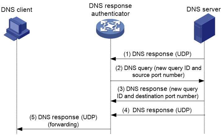
DNS response verification
The DNS response verification feature protects DNS clients against DNS response flood attacks. It is configured on the device where packets from the DNS servers to the DNS clients pass through. The device with DNS response verification feature configured is called a DNS response authenticator.
As shown in Figure 6, the DNS response verification functions as follows:
1. Upon receiving a UDP DNS response destined for a protected client, the DNS response authenticator sends back a DNS query packet with the locally generated query ID and port number.
2. After receiving the DNS query, a valid DNS server responds with a DNS response that contains a new query ID and destination port.
3. The DNS response authenticator verifies the query ID and destination port in the response. If the query ID and destination port are the same as the query ID and port number the authenticator has sent, the DNS server passes verification. The authenticator will forward subsequent packets from the server.
Figure 6 DNS response verification process
HTTP client verification
The HTTP client verification feature protects HTTP servers against HTTP flood attacks. It is configured on the device where HTTP GET or POST request packets from the HTTP clients to the HTTP servers pass through. A device with HTTP client verification feature configured is called an HTTP client authenticator.
GET request-based verification
As shown in Figure 7, the HTTP client authenticator uses HTTP GET requests to verify the HTTP client as follows:
1. Upon receiving a SYN packet destined for a protected HTTP server, the HTTP client authenticator performs TCP client verification in SYN cookie mode. If the client passes the TCP client verification, a TCP connection is established between the client and the authenticator. For more information about TCP client verification, see "TCP client verification."
2. When the authenticator receives an HTTP GET packet from the client, it performs the first redirect verification. The authenticator records the client information and responds with an HTTP Redirect packet. The HTTP Redirect packet contains a redirect URI and requires the client to terminate the TCP connection.
3. After receiving the HTTP Redirect packet, the client terminates the TCP connection and then establishes a new TCP connection with the authenticator.
4. When the authenticator receives the HTTP GET packet, it performs the second redirection verification. The authenticator verifies the following information:
¡ The client has passed the first redirection verification.
¡ The URI in the HTTP GET packet is the redirect URI.
5. If the client passes the second redirection verification, the authenticator adds its IP address to the trusted IP list, and responds a Redirect packet. The Redirect packet contains the URI that the client originally carried and requires the client to terminate the TCP connection.
6. The authenticator directly forwards the trusted client's subsequent packets to the server.
Figure 7 HTTP client verification process

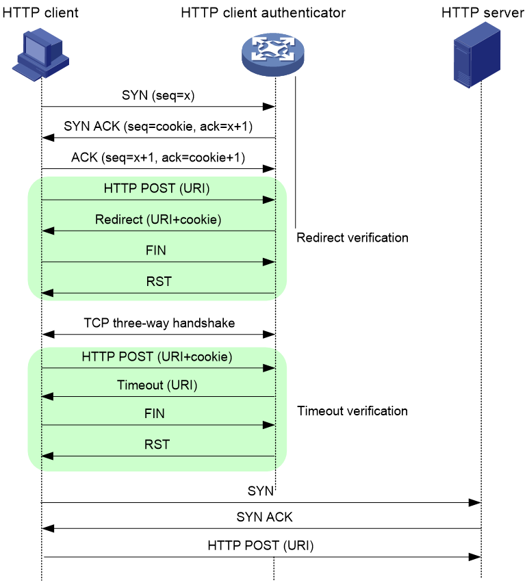
POST request-based verification
As shown in Figure 8, the HTTP client authenticator uses HTTP POST requests to verify the HTTP client as follows:
1. Upon receiving a SYN packet destined for a protected HTTP server, the HTTP client authenticator performs TCP client verification in SYN Cookie mode. If the client passes the TCP client verification, a TCP connection is established between the client and the authenticator. For more information about TCP client verification, see "TCP client verification."
2. When the authenticator receives an HTTP POST request from the client, it performs the redirect verification. The authenticator records the client information and responds with an HTTP Redirect packet. The HTTP Redirect packet contains a redirect URI and the Set-Cookie header, and requires the client to terminate the TCP connection.
3. After receiving the HTTP Redirect packet, the client terminates the TCP connection and then establishes a new TCP connection with the authenticator.
4. When the authenticator receives the HTTP POST request, it performs the timeout verification. The authenticator verifies the following information:
¡ The client has passed the redirection verification.
¡ The HTTP POST request contains a valid cookie.
5. If the client passes the timeout verification, the authenticator adds its IP address to the trusted IP list, and responds with an HTTP Timeout packet. The Timeout packet contains the URI that the client originally carried and requires the client to terminate the TCP connection.
6. The authenticator directly forwards the trusted client's subsequent packets to the server.
Figure 8 POST request-based verification process
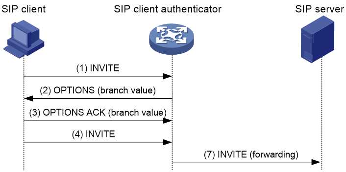
SIP client verification
The SIP client verification feature protects SIP servers against SIP flood attacks. It is configured on the device where SIP INVITE request packets from the SIP clients to the SIP servers pass through. A device with the SIP client verification feature configured is called an SIP client authenticator.
As shown in Figure 9, the SIP client verification functions as follows:
1. Upon receiving a UDP INVITE packet destined for a protected server, the SIP client authenticator sends back an OPTIONS packet with a branch value.
2. After receiving the OPTIONS packet, the client sends an OPTIONS ACK to the SIP client authenticator.
3. When receiving the OPTIONS ACK, the SIP client authenticator verifies the branch value in the OPTIONS ACK.
¡ If the branch value in the OPTIONS ACK is the same as the branch value in the OPTIONS packet that the SIP client authenticator has sent, the client passes verification. The authenticator will forward subsequent packets from the client.
¡ If the branch value in the OPTIONS ACK is different from the branch value in the OPTIONS packet that the SIP client authenticator has sent, the client fails verification. The authenticator drops packets from the client.
Figure 9 SIP client verification process
Attack detection and prevention tasks at a glance
To configure attack detection and prevention, perform the following tasks:
1. Configuring and applying an attack defense policy
a. Creating an attack defense policy
b. Configuring an attack defense policy
Choose the following tasks as needed:
- Configuring a single-packet attack defense policy
- Configuring a scanning attack defense policy
- Configuring a flood attack defense policy
- Configuring an HTTP slow attack defense policy
c. (Optional.) Configuring attack detection exemption
d. Applying an attack defense policy
Choose the following tasks as needed:
- Applying an attack defense policy to an interface
- Applying an attack defense policy to the device
2. (Optional.) Enabling log non-aggregation for single-packet attack events
3. (Optional.) Enabling the top attack statistics ranking feature
4. (Optional.) Configuring client verification
Use this feature separately or jointly with a flood attack defense policy.
¡ Configuring TCP client verification
¡ Configuring DNS client verification
¡ Configuring HTTP client verification
¡ Configuring SIP client verification
5. (Optional.) Configuring the blacklist feature
Use this feature separately or jointly with a scanning attack defense policy.
¡ Configuring the IP blacklist feature
¡ Configuring the address object group blacklist
6. (Optional.) Configuring the address object group whitelist
7. (Optional.) Configuring the login attack prevention feature
Typically, this feature is separately used.
¡ Configuring login attack prevention
Configuring and applying an attack defense policy
Creating an attack defense policy
About this task
An attack defense policy contains a set of attack detection and prevention configuration.
To configure attack defense configuration such as detection signatures and protection actions, you must first create an attack defense policy and enter its view.
Restrictions and guidelines
|
|
CAUTION: The default thresholds for triggering attack prevention might not be appropriate for your network. Set appropriate thresholds according to the actual application scenarios. Small thresholds might affect the Internet or webpage access speed. Large thresholds might make your network vulnerable to attacks. |
Procedure
1. Enter system view.
system-view
2. Create an attack defense policy and enter its view.
attack-defense policy policy-name
Configuring a single-packet attack defense policy
About this task
Apply the single-packet attack defense policy to the interface that is connected to the external network.
Single-packet attack detection inspects incoming packets based on the packet signature. If an attack packet is detected, the device can take the following actions:
· Output logs (the default action).
· Drop attack packets.
You can also configure the device to not take any actions.
Restrictions and guidelines
The logging keyword enables the attack detection and prevention module to log single-packet attack events and send log messages to the information center.
With the information center, you can set log message filtering and output rules, including output destinations.
The information center can output single-packet attack logs to any destinations except the console and the monitor terminal. If you configure the console or monitor terminal as an output destination, the output destination setting will not take effect.
To view single-packet attack logs stored on the device, use the display logbuffer command. Make sure you do not disable log output to the log buffer, which is enabled by default.
For more information about configuring the information center, see Network Management and Monitoring Configuration Guide.
Procedure
1. Enter system view.
system-view
2. Enter attack defense policy view.
attack-defense policy policy-name
3. Configure signature detection for specific single-packet attack types, and specify the actions against the attacks.
¡ Configure signature detection for well-known single-packet attacks, and specify the actions against the attacks.
signature detect { fraggle | fragment | impossible | land | large-icmp | large-icmpv6 | smurf | snork | tcp-all-flags | tcp-fin-only | tcp-invalid-flags | tcp-null-flag | tcp-syn-fin | tiny-fragment | traceroute | udp-bomb | winnuke } [ action { { drop | logging } * | none } ]
signature detect { ip-option-abnormal | ping-of-death | teardrop } action { drop | logging } *
¡ Configure signature detection for ICMP packet attacks, and specify the actions against the attacks.
signature detect icmp-type { icmp-type-value | address-mask-reply | address-mask-request | destination-unreachable | echo-reply | echo-request | information-reply | information-request | parameter-problem | redirect | source-quench | time-exceeded | timestamp-reply | timestamp-request } [ action { { drop | logging } * | none } ]
¡ Configure signature detection for ICMPv6 packet attacks, and specify the actions against the attacks.
signature detect icmpv6-type { icmpv6-type-value | destination-unreachable | echo-reply | echo-request | group-query | group-reduction | group-report | packet-too-big | parameter-problem | time-exceeded } [ action { { drop | logging } * | none } ]
¡ Configure signature detection for IP option attacks, and specify the actions against the attacks.
signature detect ip-option { option-code | internet-timestamp | loose-source-routing | record-route | route-alert | security | stream-id | strict-source-routing } [ action { { drop | logging } * | none } ]
¡ Configure signature detection for IPv6 extension header attacks, and specify the actions against the attacks.
signature detect ipv6-ext-header ext-header-value [ action { { drop | logging } * | none } ]
¡ Configure signature detection for abnormal IPv6 extension header attacks, and specify the actions against the attacks.
signature detect ipv6-ext-header-abnormal [ action { { drop | logging } * | none } ]
¡ Configure signature detection for IPv6 extension header exceeded attacks, and specify the actions against the attacks.
signature detect ipv6-ext-header-exceed [ limit limit-value ] [ action { { drop | logging } * | none } ]
By default, signature detection is not configured for single-packet attacks.
4. (Optional.) Set the maximum length of safe ICMP or ICMPv6 packets.
signature { large-icmp | large-icmpv6 } max-length length
By default, the maximum length of safe ICMP or ICMPv6 packets is 4000 bytes.
5. (Optional.) Specify the actions against single-packet attacks of a specific level.
signature level { high | info | low | medium } action { { drop | logging } * | none }
The default action is logging for single-packet attacks of the informational and low levels.
The default actions are logging and drop for single-packet attacks of the medium and high levels.
6. (Optional.) Enable signature detection for single-packet attacks of a specific level.
signature level { high | info | low | medium } detect
By default, signature detection is disabled for all levels of single-packet attacks.
Configuring a scanning attack defense policy
About this task
Apply a scanning attack defense policy to the interface that is connected to the external network.
Scanning attack detection inspects the incoming packet rate of connections to the target system. If a source initiates connections at a rate equal to or exceeding the pre-defined threshold, the device can take the following actions:
· Output logs.
· Drop subsequent packets from the IP address of the attacker.
· Add the attacker's IP address to the IP blacklist.
If logging is specified for IP sweep and port scan attacks, the system outputs logs for only IP sweep attacks when both the IP sweep and port scan attack thresholds are reached.
Restrictions and guidelines
To blacklist the attackers, you must enable the blacklist feature globally or on the interface where the defense policy is applied. For more information about the blacklist, see "Configuring the IP blacklist feature."
The logging keyword enables the attack detection and prevention module to log scanning attack events and send log messages to the information center.
With the information center, you can set log message filtering and output rules, including output destinations.
The information center can output scanning attack logs to any destinations except the console and the monitor terminal. If you configure the console or monitor terminal as an output destination, the output destination setting will not take effect.
To view scanning attack logs stored on the device, use the display logbuffer command. Make sure you do not disable log output to the log buffer, which is enabled by default.
For more information about configuring the information center, see Network Management and Monitoring Configuration Guide.
Procedure
1. Enter system view.
system-view
2. Enter attack defense policy view.
attack-defense policy policy-name
3. Configure scanning attack detection.
scan detect level { { high | low | medium } | user-defined { port-scan-threshold threshold-value | ip-sweep-threshold threshold-value } * [ period period-value ] } action { { block-source [ timeout minutes ] | drop } | logging } *
By default, scanning attack detection is not configured.
Configuring a flood attack defense policy
About this task
Apply a flood attack defense policy to the interface that is connected to the external network to protect internal servers.
Flood attack detection monitors the rate at which connections are initiated to the internal servers.
The device supports the following flood attack prevention types:
· Source-based flood attack prevention—Monitors the receiving rate of packets on a per-source IP basis. When the receiving rate of packets originating from an IP address keeps reaching or exceeding the threshold, the device enters prevention state and takes the specified defensive actions. Supported defensive actions include logging and dropping packets that originate from this IP address. When the rate drops below the silence threshold (three-fourths of the threshold), the device returns to the attack detection state.
· Destination-based flood attack prevention—Monitors the receiving rate of packets on a per-destination IP basis. When the receiving rate of packets destined for an IP address keeps reaching or exceeding the threshold, the device enters prevention state and takes the specified actions. Supported defensive actions include logging, dropping subsequent packets destined for this IP address, and client verification. When the rate drops below the silence threshold (three-fourths of the threshold), the device returns to the attack detection state.
An appropriate threshold can effectively prevent attacks. If the global threshold for triggering flood attack prevention is too low, false positives might occur, causing performance degradation or packet loss. If the global threshold is too high, false negatives might occur, making the network defenseless. Therefore, it is a good practice to enable the threshold learning feature for the device to automatically learn the global threshold. This feature allows the device to learn the global threshold based on the traffic flows in the network as follows:
1. Monitors the packet receiving rate in the network.
2. Calculates the global threshold based on the peak rate learned within the threshold learning duration.
You can choose to manually apply the learned threshold or configure the device to automatically apply the learned threshold.
The threshold learning feature includes the following modes:
· One-time learning—The device performs threshold learning only once.
· Periodic learning—The device performs threshold learning at intervals. The most recent learned threshold always takes effect.
Restrictions and guidelines for flood attack detection and prevention
If a device has multiple service cards, the global trigger threshold you set takes effect on each service card. The global trigger threshold of the device is the product of multiplying the value you set by the service card quantity.
You can configure flood attack detection and prevention for a specific IP address. Only destination-based flood attack prevention supports specifying IP addresses in the current software version. For non-specific IP addresses, the device uses the global attack prevention settings.
The logging keyword enables the attack detection and prevention module to log flood attack events and send log messages to the information center.
With the information center, you can set log message filtering and output rules, including output destinations.
The information center can output flood attack logs to any destinations except the console and the monitor terminal. If you configure the console or monitor terminal as an output destination, the output destination setting will not take effect.
To view flood attack logs stored on the device, use the display logbuffer command. Make sure you do not disable log output to the log buffer, which is enabled by default.
For more information about configuring the information center, see Network Management and Monitoring Configuration Guide.
Configuring a SYN flood attack defense policy
1. Enter system view.
system-view
2. Enter attack defense policy view.
attack-defense policy policy-name
3. Enable global SYN flood attack detection.
syn-flood detect non-specific
By default, global SYN flood attack detection is disabled.
4. Set the global threshold for triggering source-based SYN flood attack prevention.
syn-flood source-threshold threshold-value
The default setting is 10000.
5. Set the global threshold for triggering destination-based SYN flood attack prevention.
syn-flood threshold threshold-value
The default setting is 10000.
6. Specify global actions against SYN flood attacks.
syn-flood action { client-verify | drop | logging } *
By default, no global action is specified for SYN flood attacks.
7. Configure IP address-specific SYN flood attack detection.
syn-flood detect { ip ipv4-address | ipv6 ipv6-address } [ vpn-instance vpn-instance-name ] [ threshold threshold-value ] [ action { { client-verify | drop | logging } * | none } ]
By default, IP address-specific SYN flood attack detection is not configured.
Configuring an ACK flood attack defense policy
1. Enter system view.
system-view
2. Enter attack defense policy view.
attack-defense policy policy-name
3. Enable global ACK flood attack detection.
ack-flood detect non-specific
By default, global ACK flood attack detection is disabled.
4. Set the global threshold for triggering source-based ACK flood attack prevention.
ack-flood source-threshold threshold-value
The default setting is 40000.
5. Set the global threshold for triggering destination-based ACK flood attack prevention.
ack-flood threshold threshold-value
The default setting is 40000.
6. Specify global actions against ACK flood attacks.
ack-flood action { client-verify | drop | logging } *
By default, no global action is specified for ACK flood attacks.
7. Configure IP address-specific ACK flood attack detection.
ack-flood detect { ip ipv4-address | ipv6 ipv6-address } [ vpn-instance vpn-instance-name ] [ threshold threshold-value ] [ action { { client-verify | drop | logging } * | none } ]
By default, IP address-specific ACK flood attack detection is not configured.
Configuring a SYN-ACK flood attack defense policy
1. Enter system view.
system-view
2. Enter attack defense policy view.
attack-defense policy policy-name
3. Enable global SYN-ACK flood attack detection.
syn-ack-flood detect non-specific
By default, global SYN-ACK flood attack detection is disabled.
4. Set the global threshold for triggering source-based SYN-ACK flood attack prevention.
syn-ack-flood source-threshold threshold-value
The default setting is 10000.
5. Set the global threshold for triggering destination-based SYN-ACK flood attack prevention.
syn-ack-flood threshold threshold-value
The default setting is 10000.
6. Specify global actions against SYN-ACK flood attacks.
syn-ack-flood action { client-verify | drop | logging }*
By default, no global action is specified for SYN-ACK flood attacks.
7. Configure IP address-specific SYN-ACK flood attack detection.
syn-ack-flood detect { ip ipv4-address | ipv6 ipv6-address } [ vpn-instance vpn-instance-name ] [ threshold threshold-value ] [ action { { client-verify | drop | logging } * | none } ]
By default, IP address-specific SYN-ACK flood attack detection is not configured.
Configuring a FIN flood attack defense policy
1. Enter system view.
system-view
2. Enter attack defense policy view.
attack-defense policy policy-name
3. Enable global FIN flood attack detection.
fin-flood detect non-specific
By default, global FIN flood attack detection is disabled.
4. Set the global threshold for triggering source-based FIN flood attack prevention.
fin-flood source-threshold threshold-value
The default setting is 10000.
5. Set the global threshold for triggering destination-based FIN flood attack prevention.
fin-flood threshold threshold-value
The default setting is 10000.
6. Specify global actions against FIN flood attacks.
fin-flood action { client-verify | drop | logging } *
By default, no global action is specified for FIN flood attacks.
7. Configure IP address-specific FIN flood attack detection.
fin-flood detect { ip ipv4-address | ipv6 ipv6-address } [ vpn-instance vpn-instance-name ] [ threshold threshold-value ] [ action { { client-verify | drop | logging } * | none } ]
By default, IP address-specific FIN flood attack detection is not configured.
Configuring an RST flood attack defense policy
1. Enter system view.
system-view
2. Enter attack defense policy view.
attack-defense policy policy-name
3. Enable global RST flood attack detection.
rst-flood detect non-specific
By default, global RST flood attack detection is disabled.
4. Set the global threshold for triggering source-based RST flood attack prevention.
rst-flood source-threshold threshold-value
The default setting is 10000.
5. Set the global threshold for triggering destination-based RST flood attack prevention.
rst-flood threshold threshold-value
The default setting is 10000.
6. Specify global actions against RST flood attacks.
rst-flood action { client-verify | drop | logging } *
By default, no global action is specified for RST flood attacks.
7. Configure IP address-specific RST flood attack detection.
rst-flood detect { ip ipv4-address | ipv6 ipv6-address } [ vpn-instance vpn-instance-name ] [ threshold threshold-value ] [ action { { client-verify | drop | logging } * | none } ]
By default, IP address-specific RST flood attack detection is not configured.
Configuring an ICMP flood attack defense policy
1. Enter system view.
system-view
2. Enter attack defense policy view.
attack-defense policy policy-name
3. Enable global ICMP flood attack detection.
icmp-flood detect non-specific
By default, global ICMP flood attack detection is disabled.
4. Set the global threshold for triggering source-based ICMP flood attack prevention.
icmp-flood source-threshold threshold-value
The default setting is 10000.
5. Set the global threshold for triggering destination-based ICMP flood attack prevention.
icmp-flood threshold threshold-value
The default setting is 10000.
6. Specify global actions against ICMP flood attacks.
icmp-flood action { drop | logging } *
By default, no global action is specified for ICMP flood attacks.
7. Configure IP address-specific ICMP flood attack detection.
icmp-flood detect ip ip-address [ vpn-instance vpn-instance-name ] [ threshold threshold-value ] [ action { { drop | logging } * | none } ]
By default, IP address-specific ICMP flood attack detection is not configured.
Configuring an ICMPv6 flood attack defense policy
1. Enter system view.
system-view
2. Enter attack defense policy view.
attack-defense policy policy-name
3. Enable global ICMPv6 flood attack detection.
icmpv6-flood detect non-specific
By default, global ICMPv6 flood attack detection is disabled.
4. Set the global threshold for triggering source-based ICMPv6 flood attack prevention.
icmpv6-flood source-threshold threshold-value
The default setting is 10000.
5. Set the global threshold for triggering destination-based ICMPv6 flood attack prevention.
icmpv6-flood threshold threshold-value
The default setting is 10000.
6. Specify global actions against ICMPv6 flood attacks.
icmpv6-flood action { drop | logging } *
By default, no global action is specified for ICMPv6 flood attacks.
7. Configure IP address-specific ICMPv6 flood attack detection.
icmpv6-flood detect ipv6 ipv6-address [ vpn-instance vpn-instance-name ] [ threshold threshold-value ] [ action { { drop | logging } * | none } ]
By default, IP address-specific ICMPv6 flood attack detection is not configured.
Configuring a UDP flood attack defense policy
1. Enter system view.
system-view
2. Enter attack defense policy view.
attack-defense policy policy-name
3. Enable global UDP flood attack detection.
udp-flood detect non-specific
By default, global UDP flood attack detection is disabled.
4. Set the global threshold for triggering source-based UDP flood attack prevention.
udp-flood source-threshold threshold-value
The default setting is 10000.
5. Set the global threshold for triggering destination-based UDP flood attack prevention.
udp-flood threshold threshold-value
The default setting is 10000.
6. Specify global actions against UDP flood attacks.
udp-flood action { drop | logging } *
By default, no global action is specified for UDP flood attacks.
7. Configure IP address-specific UDP flood attack detection.
udp-flood detect { ip ipv4-address | ipv6 ipv6-address } [ vpn-instance vpn-instance-name ] [ threshold threshold-value ] [ action { { drop | logging } * | none } ]
By default, IP address-specific UDP flood attack detection is not configured.
Configuring a DNS flood attack defense policy
1. Enter system view.
system-view
2. Enter attack defense policy view.
attack-defense policy policy-name
3. Enable global DNS flood attack detection.
dns-flood detect non-specific
By default, global DNS flood attack detection is disabled.
4. Set the global threshold for triggering source-based DNS flood attack prevention.
dns-flood source-threshold threshold-value
The default setting is 10000.
5. Set the global threshold for triggering destination-based DNS flood attack prevention.
dns-flood threshold threshold-value
The default setting is 10000.
6. (Optional.) Specify the global ports to be protected against DNS flood attacks.
dns-flood port port-list
By default, DNS flood attack prevention protects port 53.
7. Specify global actions against DNS flood attacks.
dns-flood action { client-verify | drop | logging } *
By default, no global action is specified for DNS flood attacks.
8. Configure IP address-specific DNS flood attack detection.
dns-flood detect { ip ipv4-address | ipv6 ipv6-address } [ vpn-instance vpn-instance-name ] [ port port-list ] [ threshold threshold-value ] [ action { { client-verify | drop | logging } * | none } ]
By default, IP address-specific DNS flood attack detection is not configured.
Configuring a DNS response flood attack defense policy
1. Enter system view.
system-view
2. Enter attack defense policy view.
attack-defense policy policy-name
3. Enable global DNS response flood attack detection.
dns-reply-flood detect non-specific
By default, global DNS response flood attack detection is disabled.
4. Set the global threshold for triggering source-based DNS response flood attack prevention.
dns-reply-flood source-threshold threshold-value
The default setting is 10000.
5. Set the global threshold for triggering destination-based DNS response flood attack prevention.
dns-reply-flood threshold threshold-value
The default setting is 10000.
6. (Optional.) Specify the global ports to be protected against DNS response flood attacks.
dns-reply-flood port port-list
By default, DNS response flood attack prevention protects port 53.
7. Specify global actions against DNS response flood attacks.
dns-reply-flood action { client-verify | drop | logging } *
By default, no global action is specified for DNS response flood attacks.
8. Configure IP address-specific DNS response flood attack detection.
dns-reply-flood detect { ip ipv4-address | ipv6 ipv6-address } [ vpn-instance vpn-instance-name ] [ port port-list ] [ threshold threshold-value ] [ action { { client-verify | logging } * | none } ]
By default, IP address-specific DNS response flood attack detection is not configured.
Configuring an HTTP flood attack defense policy
1. Enter system view.
system-view
2. Enter attack defense policy view.
attack-defense policy policy-name
3. Enable global HTTP flood attack detection.
http-flood detect non-specific
By default, global HTTP flood attack detection is disabled.
4. Set the global threshold for triggering source-based HTTP flood attack prevention.
http-flood source-threshold threshold-value
The default setting is 10000.
5. Set the global threshold for triggering destination-based HTTP flood attack prevention.
http-flood threshold threshold-value
The default setting is 10000.
6. (Optional.) Specify the global ports to be protected against HTTP flood attacks.
http-flood port port-list
By default, HTTP flood attack prevention protects port 80.
7. Specify global actions against HTTP flood attacks.
http-flood action { client-verify | drop | logging } *
By default, no global action is specified for HTTP flood attacks.
8. Configure IP address-specific HTTP flood attack detection.
http-flood detect { ip ipv4-address | ipv6 ipv6-address } [ vpn-instance vpn-instance-name ] [ port port-list ] [ threshold threshold-value ] [ action { { client-verify | drop | logging } * | none } ]
By default, IP address-specific HTTP flood attack detection is not configured.
Configuring a SIP flood attack defense policy
1. Enter system view.
system-view
2. Enter attack defense policy view.
attack-defense policy policy-name
3. Enable global SIP flood attack detection.
sip-flood detect non-specific
By default, global SIP flood attack detection is disabled.
4. Set the global threshold for triggering source-based SIP flood attack prevention.
sip-flood source-threshold threshold-value
The default setting is 10000.
5. Set the global threshold for triggering destination-based SIP flood attack prevention.
sip-flood threshold threshold-value
The default setting is 10000.
6. (Optional.) Specify the global ports to be protected against SIP flood attacks.
sip-flood port port-list
By default, SIP flood attack prevention protects port 5060.
7. Specify global actions against SIP flood attacks.
sip-flood action { client-verify | drop | logging } *
By default, no global action is specified for SIP flood attacks.
8. Configure IP address-specific SIP flood attack detection.
sip-flood detect { ip ipv4-address | ipv6 ipv6-address } [ vpn-instance vpn-instance-name ] [ port port-list ] [ threshold threshold-value ] [ action { { client-verify | drop | logging } * | none } ]
By default, IP address-specific SIP flood attack detection is not configured.
Configuring threshold learning for flood attack prevention
1. Enter system view.
system-view
2. Enter attack defense policy view.
attack-defense policy policy-name
3. Enable the threshold learning feature for flood attack prevention.
threshold-learn enable
By default, the threshold learning feature for flood attack prevention is disabled.
4. (Optional.) Set the threshold learning mode.
¡ To set the one-time learning mode:
threshold-learn
mode once
¡ To set the periodic learning mode:
threshold-learn
mode periodic
By default, the one-time learning mode is used.
5. (Optional.) Set the threshold learning duration.
threshold-learn duration duration
By default, the threshold learning duration is 1440 minutes.
6. (Optional.) Set the threshold learning interval.
threshold-learn interval interval
By default, the threshold learning interval is 1440 minutes.
Skip this step for the one-time learning mode.
7. (Optional.) Set the threshold learning tolerance value.
threshold-learn tolerance-value tolerance-value
By default, the threshold learning tolerance is 50, in percentage.
Skip this step if auto application of the learned threshold is disabled.
8. (Optional.) Enable auto application of the learned threshold.
threshold-learn auto-apply enable
By default, auto application of the learned threshold is disabled.
9. Apply the most recent threshold that the device has learned.
threshold-learn apply
This command does not take effect when auto application of the learned threshold is enabled.
Configuring an HTTP slow attack defense policy
About this task
The device enters HTTP slow attack detection state when the number of HTTP concurrent connections reaches the detection triggering threshold. If the device receives an HTTP slow attack packet later, an HTTP slow attack occurs. When the number of HTTP slow attack packets exceeds the threshold within the detection period, the device takes defensive actions.
HTTP slow attack defensive actions include logging the attack events and blacklisting IP addresses of attackers.
Restrictions and guidelines
To use blacklisting as a defensive action, enable the blacklist feature.
As a best practice, specify port 80 as the global port to be protected against HTTP slow attacks. If you specify other ports by using the http-slow-attack port command, make sure these ports are used for HTTP communication. If the specified ports are not used for HTTP communication, the device resources will be wasted in inspecting non-HTTP slow attack packets.
Procedure
1. Enter system view.
system-view
2. Enter attack defense policy view.
attack-defense policy policy-name
3. Enable global HTTP slow attack detection.
http-slow-attack detect non-specific
By default, global HTTP slow attack detection is disabled.
4. Set the global thresholds for triggering HTTP slow attack prevention.
http-slow-attack threshold [ alert-number alert-number | content-length content-length | payload-length payload-length | packet-number packet-number ]*
By default, thresholds for HTTP concurrent connections, the Content-Length field value, payload size, and abnormal packets are 5000, 10000, 50, and 10, respectively.
5. Set the global HTTP slow attack detection period.
http-slow-attack period period
By default, the global HTTP slow attack detection period is 60 seconds.
6. (Optional.) Specify the global ports to be protected against HTTP slow attacks.
http-slow-attack port port-list
By default, HTTP slow attack prevention protects port 80.
7. Specify global actions against HTTP slow attacks.
http-slow-attack action { block-source [ timeout minutes ] | logging } *
By default, no global action is specified for HTTP slow attacks.
8. Configure IP address-specific HTTP slow attack detection.
http-slow-attack detect { ip ipv4-address | ipv6 ipv6-address } [ vpn-instance vpn-instance-name ] [ port port-list ] [ threshold { alert-number alert-number | content-length content-length | payload-length payload-length | packet-number packet-number }* ] [ period period ] [ action { block-source [ timeout minutes ] | logging }* ]
By default, IP address-specific HTTP slow attack detection is not configured.
Configuring attack detection exemption
About this task
The attack defense policy uses the ACL to identify exempted packets. The policy does not check the packets permitted by the ACL. You can configure the ACL to identify packets from trusted servers. The exemption feature reduces the false alarm rate and improves packet processing efficiency. For example, the attack defense policy identifies multicast packets with the same source addresses and different destination addresses as scanning attack packets (for example, OSPF or PIM packets). You can configure an ACL to exempt such packets from attack detection.
Restrictions and guidelines
If an ACL is used for attack detection exemption, only the following match criteria in the ACL permit rules take effect:
· Source IP address.
· Destination IP address.
· Source port.
· Destination port.
· Protocol.
· L3VPN instance.
· The fragment keyword for matching non-first fragments.
Procedure
1. Enter system view.
system-view
2. Enter attack defense policy view.
attack-defense policy policy-name
3. Configure attack detection exemption.
exempt acl [ ipv6 ] { acl-number | name acl-name }
By default, attack detection exemption is not configured.
Applying an attack defense policy to an interface
1. Enter system view.
system-view
2. Enter system view.
interface interface-type interface-number
3. Apply an attack defense policy to the interface.
attack-defense apply policy policy-name
By default, no attack defense policy is applied to the interface.
Applying an attack defense policy to the device
About this task
An attack defense policy applied to the device itself rather than the interfaces detects packets destined for the device and prevents attacks targeted at the device.
Applying an attack defense policy can improve the efficiency of processing attack packets destined for the device.
If a device and its interfaces have attack defense policies applied, a packet destined for the device is processed as follows:
1. The policy applied to the receiving interface processes the packet.
2. If the packet is not dropped by the receiving interface, the policy applied to the device processes the packet.
Procedure
1. Enter system view.
system-view
2. Apply an attack defense policy to the device.
attack-defense local apply policy policy-name
By default, no attack defense policy is applied to the device.
Enabling log non-aggregation for single-packet attack events
About this task
Log aggregation aggregates multiple logs generated during a period of time and sends one log. Logs that are aggregated must have the following attributes in common:
· Attacks are detected on the same interface or are destined for the device.
· Attack type.
· Attack defense action.
· Source and destination IP addresses.
· VPN instance to which the victim IP address belongs.
Restrictions and guidelines
As a best practice, do not disable log aggregation. A large number of logs will consume the display resources of the console.
Procedure
1. Enter system view.
system-view
2. Enable log non-aggregation for single-packet attack events.
attack-defense signature log non-aggregate
By default, log non-aggregation is disabled for single-packet attack events.
Enabling the top attack statistics ranking feature
About this task
This feature collects statistics about dropped attack packets based on attacker, victim, and attack type and ranks the top attack statistics by attacker and victim. To display the top attack statistics rankings, use the display attack-defense top-attack-statistics command.
Procedure
1. Enter system view.
system-view
2. Enable the top attack statistics ranking feature.
attack-defense top-attack-statistics enable
By default, the top attack statistics ranking feature is disabled.
Configuring TCP client verification
About this task
Configure TCP client verification on the interface that is connected to the external network. TCP client verification protects internal TCP servers against TCP flood attacks, including the following flood attacks:
· SYN.
· SYN-ACK.
· RST.
· FIN.
· ACK.
IP addresses protected by TCP client verification can be manually added or automatically learned:
· You can manually add protected IP addresses. The device performs client verification when it receives the first SYN packet destined for a protected IP address.
· The TCP client verification can automatically add victims' IP addresses to the protected IP list when collaborating with flood attack detection. Make sure client-verify is specified as the flood attack prevention action. For more information, see "Configuring a flood attack defense policy."
If a TCP client is verified legitimate in safe reset mode, the device adds the client's IP address to the trusted IP list. The device directly forwards TCP packets from trusted IP addresses.
Procedure
1. Enter system view.
system-view
2. (Optional.) Specify an IP address to be protected by the TCP client verification feature.
client-verify tcp protected { ip destination-ip-address | ipv6 destination-ipv6-address } [ vpn-instance vpn-instance-name ] [ port port-number ]
3. Enter interface view.
interface interface-type interface-number
4. Enable TCP client verification.
¡ Set the safe reset mode.
client-verify tcp enable mode safe-reset
¡ Set the SYN cookie mode.
client-verify tcp enable [ mode syn-cookie ]
By default, TCP client verification is disabled.
Configuring DNS client verification
About this task
Configure DNS client verification on the interface that is connected to the external network. The DNS client verification protects internal DNS servers against DNS flood attacks.
IP addresses protected by DNS client verification can be manually added or automatically learned:
· You can manually add protected IP addresses. The device performs client verification when it receives the first DNS query destined for a protected IP address.
· The DNS client verification can automatically add victims' IP addresses to the protected IP list when collaborating with DNS flood attack detection. Make sure client-verify is specified as the DNS flood attack prevention action. For more information, see "Configuring a DNS flood attack defense policy."
If a DNS client is verified legitimate, the device adds the client's IP address to the trusted IP list. The device directly forwards DNS packets from trusted IP addresses.
Procedure
1. Enter system view.
system-view
2. (Optional.) Specify an IP address to be protected by the DNS client verification feature.
client-verify dns protected { ip destination-ip-address | ipv6 destination-ipv6-address } [ vpn-instance vpn-instance-name ] [ port port-number ]
3. Enterinterface view.
interface interface-type interface-number
4. Enable DNS client verification.
client-verify dns enable
By default, DNS client verification is disabled.
Configuring DNS response verification
About this task
Configure DNS response verification on the interface that is connected to the external network. The DNS response verification protects internal DNS clients against DNS response flood attacks.
IP addresses protected by DNS response verification can be manually added or automatically learned:
· You can manually add protected IP addresses. The device performs response verification when it receives the first DNS response destined for a protected IP address.
· The DNS response verification can automatically add victims' IP addresses to the protected IP list when collaborating with DNS response flood attack detection. Make sure client-verify is specified as the DNS response flood attack prevention action. For more information, see "Configuring a DNS response flood attack defense policy."
If a DNS server is verified legitimate, the device adds the client's IP address to the trusted IP list. The device directly forwards DNS responses from trusted IP addresses.
Restrictions and guidelines
The DNS response verification feature requires that servers use the standard TCP/IP protocol suite and DNS protocol. Legitimate servers that use non-standard protocols will be verified as illegitimate by the DNS response authenticator.
Procedure
1. Enter system view.
system-view
2. (Optional.) Specify an IP address to be protected by the DNS response verification feature.
Client-verify dns-reply protected { ip destination-ip-address | ipv6 destination-ipv6-address } [ vpn-instance vpn-instance-name ] [ port port-number ]
3. Enter interface view.
interface interface-type interface-number
4. Enable DNS response verification.
client-verify dns-reply enable
By default, DNS response verification is disabled.
Configuring HTTP client verification
About this task
Configure HTTP client verification on the interface that is connected to the external network. The HTTP client verification protects internal HTTP servers against HTTP flood attacks.
IP addresses protected by HTTP client verification can be manually added or automatically learned:
· You can manually add protected IP addresses. The device performs client verification when it receives the first HTTP GET or POST packet destined for a protected IP address.
· The HTTP client verification can automatically add victims' IP addresses to the protected IP list when collaborating with HTTP flood attack detection. Make sure client-verify is specified as the HTTP flood attack prevention action. For more information, see "Configuring an HTTP flood attack defense policy."
If an HTTP client is verified legitimate, the device adds the client's IP address to the trusted IP list. The device directly forwards HTTP packets from trusted IP addresses.
Procedure
1. Enter system view.
system-view
2. (Optional.) Specify an IP address to be protected by the HTTP client verification feature.
client-verify http protected { ip destination-ip-address | ipv6 destination-ipv6-address } [ vpn-instance vpn-instance-name ] [ port port-number ]
3. Enter interface view.
interface interface-type interface-number
4. Enable HTTP client verification.
client-verify http enable
By default, HTTP client verification is disabled.
Configuring SIP client verification
About this task
Configure SIP client verification on the interface that is connected to the external network. The SIP client verification protects internal SIP servers against SIP flood attacks.
IP addresses protected by SIP client verification can be manually added or automatically learned:
· You can manually add protected IP addresses. The device performs client verification when it receives the first INVITE packet destined for a protected IP address.
· The SIP client verification can automatically add victims' IP addresses to the protected IP list when collaborating with SIP flood attack detection. Make sure client-verify is specified as the SIP flood attack prevention action. For more information, see "Configuring a SIP flood attack defense policy."
If a SIP client is verified legitimate, the device adds the client's IP address to the trusted IP list. The device directly forwards SIP packets from trusted IP addresses.
Restrictions and guidelines
A legitimate SIP client might not pass the client verification if packets sent by the SIP client do not contain complete header information due to fragmentation.
Procedure
1. Enter system view.
system-view
2. (Optional.) Specify an IP address to be protected by the SIP client verification feature.
client-verify sip protected { ip destination-ip-address | ipv6 destination-ipv6-address } [ vpn-instance vpn-instance-name ] [ port port-number ]
3. Enter interface view.
interface interface-type interface-number
4. Enable SIP client verification.
client-verify sip enable
By default, SIP client verification is disabled.
Configuring the IP blacklist feature
About this task
The IP blacklist feature filters packets sourced from or destined for IP addresses in blacklist entries. If the global blacklist feature is enabled, the blacklist feature is enabled on all interfaces.
You can manually add source or destination IP blacklist entries. When creating such an entry, you can set an aging time for it. Entries without the aging time do not age out unless you delete them manually.
The device can automatically add source IP blacklist entries when collaborating with scanning attack detection. Each dynamically learned source IP blacklist entry has an aging time, which is user configurable. Make sure the block-source keyword is specified as the scanning attack prevention action. For more information about the scanning attack detection and prevention, see "Configuring a scanning attack defense policy."
Procedure
1. Enter system view.
system-view
2. (Optional.) Add an IP blacklist entry.
¡ Add a source IPv4 blacklist entry.
blacklist ip source-ip-address [ vpn-instance vpn-instance-name ] [ ds-lite-peer ds-lite-peer-address ] [ timeout minutes ]
¡ Add a source IPv6 blacklist entry.
blacklist ipv6 source-ipv6-address [ vpn-instance vpn-instance-name ] [ timeout minutes ]
¡ Add a destination IPv4 blacklist entry.
blacklist destination-ip destination-ip-address [ vpn-instance vpn-instance-name ] [ timeout minutes ]
¡ Add a destination IPv6 blacklist entry.
blacklist destination-ipv6 destination -ipv6-address [ vpn-instance vpn-instance-name ] [ timeout minutes ]
3. (Optional.) Enable logging for the blacklist feature.
blacklist logging enable
By default, logging is disabled for the blacklist feature.
4. Enable the blacklist feature. Choose one option as needed:
¡ Enable the global blacklist feature.
blacklist global enable
By default, the global blacklist feature is disabled.
¡ Execute the following commands in sequence to enable the blacklist feature on an interface:
interface interface-type interface-number
blacklist enable
By default, the blacklist feature is disabled on the interface.
Configuring the address object group blacklist
About this task
This feature filters packets sourced from the subnets specified in the blacklisted address object group.
Hardware and feature compatibility
|
Hardware |
Feature compatibility |
|
MSR810, MSR810-W, MSR810-W-DB, MSR810-LM, MSR810-W-LM, MSR810-10-PoE, MSR810-LM-HK, MSR810-W-LM-HK, MSR810-LM-CNDE-SJK, MSR810-CNDE-SJK |
Yes |
|
MSR810-LMS, MSR810-LUS |
No |
|
MSR810-LMS-EA, MSR810-LME |
Yes |
|
MSR1004S-5G |
Yes |
|
MSR2600-6-X1, MSR2600-10-X1 |
Yes |
|
MSR 2630 |
Yes |
|
MSR3600-28, MSR3600-51 |
Yes |
|
MSR3600-28-SI, MSR3600-51-SI |
Yes |
|
MSR3600-28-X1, MSR3600-28-X1-DP, MSR3600-51-X1, MSR3600-51-X1-DP |
Yes |
|
MSR3610-I-DP, MSR3610-IE-DP, MSR3610-IE-ES, MSR3610-IE-EAD, MSR-EAD-AK770, MSR3610-I-IG, MSR3610-IE-IG |
Yes |
|
MSR3610-X1, MSR3610-X1-DP, MSR3610-X1-DC, MSR3610-X1-DP-DC, MSR3620-X1, MSR3640-X1 |
Yes |
|
MSR 3610, MSR 3620, MSR 3620-DP, MSR 3640, MSR 3660 |
Yes |
|
MSR3610-G, MSR3620-G |
Yes |
|
MSR3640-X1-HI |
Yes |
|
Hardware |
Feature compatibility |
|
MSR810-W-WiNet, MSR810-LM-WiNet |
Yes |
|
MSR830-4LM-WiNet |
Yes |
|
MSR830-5BEI-WiNet, MSR830-6EI-WiNet, MSR830-10BEI-WiNet |
Yes |
|
MSR830-6BHI-WiNet, MSR830-10BHI-WiNet |
Yes |
|
MSR2600-6-WiNet, MSR2600-10-X1-WiNet |
Yes |
|
MSR2630-WiNet |
Yes |
|
MSR3600-28-WiNet |
Yes |
|
MSR3610-X1-WiNet |
Yes |
|
MSR3610-WiNet, MSR3620-10-WiNet, MSR3620-DP-WiNet, MSR3620-WiNet, MSR3660-WiNet |
Yes |
|
Hardware |
Feature compatibility |
|
MSR2630-XS |
Yes |
|
MSR3600-28-XS |
Yes |
|
MSR3610-XS |
Yes |
|
MSR3620-XS |
Yes |
|
MSR3610-I-XS |
Yes |
|
MSR3610-IE-XS |
Yes |
|
MSR3620-X1-XS |
Yes |
|
MSR3640-XS |
Yes |
|
MSR3660-XS |
Yes |
|
Hardware |
Feature compatibility |
|
MSR810-LM-GL |
Yes |
|
MSR810-W-LM-GL |
Yes |
|
MSR830-6EI-GL |
Yes |
|
MSR830-10EI-GL |
Yes |
|
MSR830-6HI-GL |
Yes |
|
MSR830-10HI-GL |
Yes |
|
MSR1004S-5G-GL |
Yes |
|
MSR2600-6-X1-GL |
Yes |
|
MSR3600-28-SI-GL |
Yes |
Restrictions and guidelines
An address object group can only be manually added to or deleted from the blacklist.
The address object group blacklist feature must be used together with the address object group feature. For more information about address object groups, see "Configuring object groups."
Procedure
1. Enter system view.
system-view
2. Add an address object group to the blacklist.
blacklist object-group object-group-name
By default, no address object group is on the blacklist.
3. Enable the blacklist feature. Choose one option as needed:
¡ Enable the global blacklist feature.
blacklist global enable
By default, the global blacklist feature is disabled.
¡ Enter interface view and enable the blacklist feature on the interface.
interface interface-type interface-number
blacklist enable
By default, the blacklist feature is disabled on the interface.
Configuring the address object group whitelist
About this task
This feature exempts packets sourced from the subnets specified in the whitelisted address object group from attack detection.
Hardware and feature compatibility
|
Hardware |
Feature compatibility |
|
MSR810, MSR810-W, MSR810-W-DB, MSR810-LM, MSR810-W-LM, MSR810-10-PoE, MSR810-LM-HK, MSR810-W-LM-HK, MSR810-LM-CNDE-SJK, MSR810-CNDE-SJK |
Yes |
|
MSR810-LMS, MSR810-LUS |
No |
|
MSR810-LMS-EA, MSR810-LME |
Yes |
|
MSR1004S-5G |
Yes |
|
MSR2600-6-X1, MSR2600-10-X1 |
Yes |
|
MSR 2630 |
Yes |
|
MSR3600-28, MSR3600-51 |
Yes |
|
MSR3600-28-SI, MSR3600-51-SI |
Yes |
|
MSR3600-28-X1, MSR3600-28-X1-DP, MSR3600-51-X1, MSR3600-51-X1-DP |
Yes |
|
MSR3610-I-DP, MSR3610-IE-DP, MSR3610-IE-ES, MSR3610-IE-EAD, MSR-EAD-AK770, MSR3610-I-IG, MSR3610-IE-IG |
Yes |
|
MSR3610-X1, MSR3610-X1-DP, MSR3610-X1-DC, MSR3610-X1-DP-DC, MSR3620-X1, MSR3640-X1 |
Yes |
|
MSR 3610, MSR 3620, MSR 3620-DP, MSR 3640, MSR 3660 |
Yes |
|
MSR3610-G, MSR3620-G |
Yes |
|
MSR3640-X1-HI |
Yes |
|
Hardware |
Feature compatibility |
|
MSR810-W-WiNet, MSR810-LM-WiNet |
Yes |
|
MSR830-4LM-WiNet |
Yes |
|
MSR830-5BEI-WiNet, MSR830-6EI-WiNet, MSR830-10BEI-WiNet |
Yes |
|
MSR830-6BHI-WiNet, MSR830-10BHI-WiNet |
Yes |
|
MSR2600-6-WiNet, MSR2600-10-X1-WiNet |
Yes |
|
MSR2630-WiNet |
Yes |
|
MSR3600-28-WiNet |
Yes |
|
MSR3610-X1-WiNet |
Yes |
|
MSR3610-WiNet, MSR3620-10-WiNet, MSR3620-DP-WiNet, MSR3620-WiNet, MSR3660-WiNet |
Yes |
|
Hardware |
Feature compatibility |
|
MSR2630-XS |
Yes |
|
MSR3600-28-XS |
Yes |
|
MSR3610-XS |
Yes |
|
MSR3620-XS |
Yes |
|
MSR3610-I-XS |
Yes |
|
MSR3610-IE-XS |
Yes |
|
MSR3620-X1-XS |
Yes |
|
MSR3640-XS |
Yes |
|
MSR3660-XS |
Yes |
|
Hardware |
Feature compatibility |
|
MSR810-LM-GL |
Yes |
|
MSR810-W-LM-GL |
Yes |
|
MSR830-6EI-GL |
Yes |
|
MSR830-10EI-GL |
Yes |
|
MSR830-6HI-GL |
Yes |
|
MSR830-10HI-GL |
Yes |
|
MSR1004S-5G-GL |
Yes |
|
MSR2600-6-X1-GL |
Yes |
|
MSR3600-28-SI-GL |
Yes |
Restrictions and guidelines
An address object group can only be manually added to or deleted from the whitelist.
The address object group whitelist feature must be used together with the address object group feature. For more information about address object groups, see "Configuring object groups."
Procedure
1. Enter system view.
system-view
2. Add an address object group to the whitelist.
whitelist object-group object-group-name
By default, no address object group is added to the whitelist.
3. Enable the whitelist feature. Choose one option as needed:
¡ Enable the global whitelist feature.
whitelist global enable
By default, the global whitelist feature is disabled.
¡ Enter interface view and enable the whitelist feature on the interface.
interface interface-type interface-number
whitelist enable
By default, the whitelist feature is disabled on the interface.
Configuring login attack prevention
About this task
The login attack prevention feature detects a login DoS attack if a user fails the maximum number of successive login attempts. The feature triggers the blacklist feature to add the user's IP to the blacklist. Following login attempts from the user is blocked for the block period. For login attack prevention to take effect, you must enable the global blacklist feature.
This feature can effectively prevent login DoS attacks.
Hardware and feature compatibility
|
Hardware |
Feature compatibility |
|
MSR810, MSR810-W, MSR810-W-DB, MSR810-LM, MSR810-W-LM, MSR810-10-PoE, MSR810-LM-HK, MSR810-W-LM-HK, MSR810-LM-CNDE-SJK, MSR810-CNDE-SJK |
No |
|
MSR810-LMS, MSR810-LUS |
Yes |
|
MSR810-LMS-EA, MSR810-LME |
No |
|
MSR1004S-5G |
Yes |
|
MSR2600-6-X1, MSR2600-10-X1 |
Yes |
|
MSR 2630 |
Yes |
|
MSR3600-28, MSR3600-51 |
Yes |
|
MSR3600-28-SI, MSR3600-51-SI |
Yes |
|
MSR3600-28-X1, MSR3600-28-X1-DP, MSR3600-51-X1, MSR3600-51-X1-DP |
Yes |
|
MSR3610-I-DP, MSR3610-IE-DP, MSR3610-IE-ES, MSR3610-IE-EAD, MSR-EAD-AK770, MSR3610-I-IG, MSR3610-IE-IG |
Yes |
|
MSR3610-X1, MSR3610-X1-DP, MSR3610-X1-DC, MSR3610-X1-DP-DC, MSR3620-X1, MSR3640-X1 |
Yes |
|
MSR 3610, MSR 3620, MSR 3620-DP, MSR 3640, MSR 3660 |
Yes |
|
MSR3610-G, MSR3620-G |
Yes |
|
MSR3640-X1-HI |
Yes |
|
Hardware |
Feature compatibility |
|
MSR810-W-WiNet, MSR810-LM-WiNet |
Yes |
|
MSR830-4LM-WiNet |
Yes |
|
MSR830-5BEI-WiNet, MSR830-6EI-WiNet, MSR830-10BEI-WiNet |
Yes |
|
MSR830-6BHI-WiNet, MSR830-10BHI-WiNet |
Yes |
|
MSR2600-6-WiNet, MSR2600-10-X1-WiNet |
Yes |
|
MSR2630-WiNet |
Yes |
|
MSR3600-28-WiNet |
Yes |
|
MSR3610-X1-WiNet |
Yes |
|
MSR3610-WiNet, MSR3620-10-WiNet, MSR3620-DP-WiNet, MSR3620-WiNet, MSR3660-WiNet |
Yes |
|
Hardware |
Feature compatibility |
|
MSR2630-XS |
Yes |
|
MSR3600-28-XS |
Yes |
|
MSR3610-XS |
Yes |
|
MSR3620-XS |
Yes |
|
MSR3610-I-XS |
Yes |
|
MSR3610-IE-XS |
Yes |
|
MSR3620-X1-XS |
Yes |
|
MSR3640-XS |
Yes |
|
MSR3660-XS |
Yes |
|
Hardware |
Feature compatibility |
|
MSR810-LM-GL |
No |
|
MSR810-W-LM-GL |
No |
|
MSR830-6EI-GL |
Yes |
|
MSR830-10EI-GL |
Yes |
|
MSR830-6HI-GL |
Yes |
|
MSR830-10HI-GL |
Yes |
|
MSR1004S-5G-GL |
Yes |
|
MSR2600-6-X1-GL |
Yes |
|
MSR3600-28-SI-GL |
Yes |
Procedure
1. Enter system view.
system-view
2. Enable login attack prevention.
attack-defense login enable
By default, login attack prevention is disabled.
3. Set the maximum number of successive login failures.
attack-defense login max-attempt max-attempt
The default value is three.
4. Set the block period during which a login attempt is blocked.
attack-defense login block-timeout minutes
The default value is 60 minutes.
5. Enable the global blacklist feature.
blacklist global enable
By default, the global blacklist feature is disabled.
Enabling the login delay
About this task
The login delay feature delays the device from accepting a login request from a user after the user fails a login attempt. This feature can slow down login dictionary attacks.
The login delay feature is independent of the login attack prevention feature.
Procedure
1. Enter system view.
system-view
2. Enable the login delay feature.
attack-defense login reauthentication-delay seconds
By default, the login delay feature is disabled. The device does not delay accepting a login request from a user who has failed a login attempt.
Display and maintenance commands for attack detection and prevention
Use the display commands in any view and the reset commands in user view.
To display and maintain attack detection and prevention:
|
Task |
Command |
|
Display flood attack detection and prevention statistics for an IPv4 address. |
In standalone mode: display attack-defense { ack-flood | dns-flood | dns-reply-flood | fin-flood | flood | http-flood | icmp-flood | rst-flood | sip-flood | syn-ack-flood | syn-flood | udp-flood } statistics ip [ ip-address [ vpn vpn-instance-name ] ] [ interface interface-type interface-number | local ] [ count ] In IRF mode: display attack-defense { ack-flood | dns-flood | dns-reply-flood | fin-flood | flood | http-flood | icmp-flood | rst-flood | sip-flood | syn-ack-flood | syn-flood | udp-flood } statistics ip [ ip-address [ vpn vpn-instance-name ] ] [ [ interface interface-type interface-number | local ] [ slot slot-number ] ] [ count ] |
|
Display flood attack detection and prevention statistics for an IPv6 address. |
In standalone mode: display attack-defense { ack-flood | dns-flood | dns-reply-flood | fin-flood | flood | http-flood | icmpv6-flood | rst-flood | sip-flood | syn-ack-flood | syn-flood | udp-flood } statistics ipv6 [ ipv6-address [ vpn vpn-instance-name ] ] [ interface interface-type interface-number | local ] [ count ] In IRF mode: display attack-defense { ack-flood | dns-flood | dns-reply-flood | fin-flood | flood | http-flood | icmpv6-flood | rst-flood | sip-flood | syn-flood | syn-ack-flood | udp-flood } statistics ipv6 [ ipv6-address [ vpn vpn-instance-name ] ] [ [ interface interface-type interface-number | local ] [ slot slot-number ] ] [ count ] |
|
Display statistics about IPv4 HTTP slow attack detection and prevention. |
In standalone mode: display attack-defense http-slow-attack statistics ip [ ip-address [ vpn-instance vpn-instance-name ] ] [ interface { interface-type interface-number | interface-name } | local ] [ count ] In IRF mode: display attack-defense http-slow-attack statistics ip [ ip-address [ vpn-instance vpn-instance-name ] ] [ [ interface { interface-type interface-number | interface-name } | local ] [ slot slot-number ] ] [ count ] |
|
Display statistics about IPv6 HTTP slow attack detection and prevention. |
In standalone mode: display attack-defense http-slow-attack statistics ipv6 [ ipv6-address [ vpn-instance vpn-instance-name ] ] [ interface { interface-type interface-number | interface-name } | local ] [ count ] In IRF mode: display attack-defense http-slow-attack statistics ipv6 [ ipv6-address [ vpn-instance vpn-instance-name ] ] [ [ interface { interface-type interface-number | interface-name } | local ] [ slot slot-number ] ] [ count ] |
|
Display attack defense policy configuration. |
display attack-defense policy [ policy-name ] |
|
Display information about IPv4 addresses protected by flood attack detection and prevention. |
In standalone mode: display attack-defense policy policy-name { ack-flood | dns-flood | dns-reply-flood | fin-flood | flood | http-flood | icmp-flood | rst-flood | sip-flood | syn-ack-flood | syn-flood | udp-flood } ip [ ip-address [ vpn vpn-instance-name ] ] [ count ] In IRF mode: display attack-defense policy policy-name { ack-flood | dns-flood | dns-reply-flood | fin-flood | flood | http-flood | icmp-flood | rst-flood | sip-flood | syn-ack-flood | syn-flood | udp-flood } ip [ ip-address [ vpn vpn-instance-name ] ] [ slot slot-number ] [ count ] |
|
Display information about IPv6 addresses protected by flood attack detection and prevention. |
In standalone mode: display attack-defense policy policy-name { ack-flood | dns-flood | dns-reply-flood | fin-flood | flood | http-flood | icmpv6-flood | rst-flood | sip-flood | syn-ack-flood | syn-flood | udp-flood } ipv6 [ ipv6-address [ vpn vpn-instance-name ] ] [ count ] In IRF mode: display attack-defense policy policy-name { ack-flood | dns-flood | dns-reply-flood | fin-flood | flood | http-flood | icmpv6-flood | rst-flood | sip-flood | syn-ack-flood | syn-flood | udp-flood } ipv6 [ ipv6-address [ vpn vpn-instance-name ] ] [ slot slot-number ] ] [ count ] |
|
Display information about IPv4 scanning attackers. |
In standalone mode: display attack-defense scan attacker ip [ interface interface-type interface-number | local ] [ count ] In IRF mode: display attack-defense scan attacker ip [ [ interface interface-type interface-number | local ] [ slot slot-number ] ] [ count ] |
|
Display information about IPv6 scanning attackers. |
In standalone mode: display attack-defense scan attacker ipv6 [ interface interface-type interface-number | local ] [ count ] In IRF mode: display attack-defense scan attacker ipv6 [ [ interface interface-type interface-number | local ] [ slot slot-number ] ] [ count ] |
|
Display attack detection and prevention statistics on an interface. |
In standalone mode: display attack-defense statistics interface interface-type interface-number In IRF mode: display attack-defense statistics interface interface-type interface-number [ slot slot-number ] |
|
Display attack detection and prevention statistics for the device. |
In standalone mode: display attack-defense statistics local In IRF mode: display attack-defense statistics local [ slot slot-number ] |
|
Display top 10 attack statistics. |
display attack-defense top-attack-statistics { last-1-hour | last-24-hours | last-30-days } [ by-attacker | by-type | by-victim ] |
|
Display destination IPv4 blacklist entries. |
In standalone mode: display blacklist destination-ip [ destination-ip-address [ vpn-instance vpn-instance-name ] ] [ count ] In IRF mode: display blacklist destination-ip [ destination-ip-address [ vpn-instance vpn-instance-name ] ] [ slot slot-number ] [ count ] |
|
Display destination IPv6 blacklist entries. |
In standalone mode: display blacklist destination-ipv6 [ destination-ipv6-address [ vpn-instance vpn-instance-name ] ] [ count ] In IRF mode: display blacklist destination-ipv6 [ destination-ipv6-address [ vpn-instance vpn-instance-name ] ] [ slot slot-number ] [ count ] |
|
Display source IPv4 blacklist entries. |
In standalone mode: display blacklist ip [ source-ip-address [ vpn-instance vpn-instance-name ] [ ds-lite-peer ds-lite-peer-address ] | count ] In IRF mode: display blacklist ip [ source-ip-address [ vpn-instance vpn-instance-name ] [ ds-lite-peer ds-lite-peer-address ] ] [ slot slot-number ] [ count ] |
|
Display source IPv6 blacklist entries. |
In standalone mode: display blacklist ipv6 [ source-ipv6-address [ vpn-instance vpn-instance-name ] | count ] In IRF mode: display blacklist ipv6 [ source-ipv6-address [ vpn-instance vpn-instance-name ] ] [ slot slot-number ] [ count ] |
|
Display protected IPv4 addresses for client verification. |
In standalone mode: display client-verify { dns | dns-reply | http | sip | tcp } protected ip [ ip-address [ vpn vpn-instance-name ] ] [ port port-number ] [ count ] In IRF mode: display client-verify { dns | dns-reply | http | sip | tcp } protected ip [ ip-address [ vpn vpn-instance-name ] ] [ port port-number ] [ slot slot-number ] [ count ] |
|
Display protected IPv6 addresses for client verification. |
In standalone mode: display client-verify { dns | dns-reply | http | sip | tcp } protected ipv6 [ ipv6-address [ vpn vpn-instance-name ] ] [ port port-number ] [ count ] In IRF mode: display client-verify { dns | dns-reply | http | sip | tcp } protected ipv6 [ ipv6-address [ vpn vpn-instance-name ] ] [ port port-number ] [ slot slot-number ] [ count ] |
|
Display trusted IPv4 addresses for client verification. |
In standalone mode: display client-verify { dns | dns-reply | http | sip | tcp } trusted ip [ ip-address [ vpn vpn-instance-name ] ] [ count ] In IRF mode: display client-verify { dns | dns-reply | http | sip | tcp } trusted ip [ ip-address [ vpn vpn-instance-name ] ] [ slot slot-number ] [ count ] |
|
Display trusted IPv6 addresses for client verification. |
In standalone mode: display client-verify { dns | dns-reply | http | sip | tcp } trusted ipv6 [ ipv6-address [ vpn vpn-instance-name ] ] [ count ] In IRF mode: display client-verify { dns | dns-reply | http | sip | tcp } trusted ipv6 [ ipv6-address [ vpn vpn-instance-name ] ] [ slot slot-number ] ] [ count ] |
|
Display statistics about packets that match the address object groups on the whitelist. |
In standalone mode: display whitelist object-group [ object-group-name ] In IRF mode: display whitelist object-group [ object-group-name ] [ slot slot-number ] |
|
Clear flood attack detection and prevention statistics. |
reset attack-defense policy policy-name flood protected { ip | ipv6 } statistics |
|
Clear attack detection and prevention statistics for an interface. |
reset attack-defense statistics interface interface-type interface-number |
|
Clear attack detection and prevention statistics for the device. |
reset attack-defense statistics local |
|
Clear top 10 attack statistics. |
reset attack-defense top-attack-statistics |
|
Delete dynamic destination IPv4 blacklist entries. |
reset blacklist destination-ip { destination-ip-address [ vpn-instance vpn-instance-name ] | all } |
|
Delete dynamic destination IPv6 blacklist entries. |
reset blacklist destination-ipv6{ destination-ipv6-address [ vpn-instance vpn-instance-name ] | all } |
|
Delete dynamic source IPv4 blacklist entries. |
reset blacklist ip { source-ip-address [ vpn-instance vpn-instance-name ] [ ds-lite-peer ds-lite-peer-address ] | all } |
|
Delete dynamic source IPv6 blacklist entries. |
reset blacklist ipv6 { source-ipv6-address [ vpn-instance vpn-instance-name ] | all } |
|
Clear blacklist statistics. |
reset blacklist statistics |
|
Clear protected IP statistics for client verification. |
reset client-verify { dns | dns-reply | http | sip | tcp } protected { ip | ipv6 } statistics |
|
Clear the trusted IP list for client verification. |
reset client-verify { dns | dns-reply | http | sip | tcp } trusted { ip | ipv6 } |
|
Clear statistics about packets that match the address object groups on the whitelist. |
reset whitelist statistics |
Attack detection and prevention configuration examples
Example: Configuring interface-based attack detection and prevention
Network configuration
As shown in Figure 10, the router is the gateway for the internal network.
Configure an attack defense policy and apply the policy to GigabitEthernet 1/0/2 to meet the following requirements:
· Provide low-level scanning attack detection for internal hosts and servers. If a scanning attack is detected, log the attack and keep the attacker on the blacklist for 10 minutes.
· Protect internal hosts and servers against smurf attacks. If a smurf attack is detected, log the attack.
· Protect the internal server against SYN flood attacks. If the number of SYN packets sent to the server per second reaches or exceeds 5000, log the attack and drop subsequent packets.
· Protect the internal server against HTTP slow attacks. The router enters HTTP slow attack detection state when the number of HTTP concurrent connections to port 80 and 8080 exceeds 3000. When the router receives more than 10 HTTP slow attack packets within 60 seconds, the device generates a log and adds the attack source to the IP blacklist.
Procedure
# Configure IP addresses for the interfaces on the router. (Details not shown.)
# Enable the global blacklist feature.
<Router> system-view
[Router] blacklist global enable
# Create attack defense policy a1.
[Router] attack-defense policy a1
# Configure signature detection for smurf attacks, and specify logging as the prevention action.
[Router-attack-defense-policy-a1] signature detect smurf action logging
# Configure low-level scanning attack detection, specify logging and block-source as the prevention actions, and set the blacklist entry aging time to 10 minutes.
[Router-attack-defense-policy-a1] scan detect level low action logging block-source timeout 10
# Configure SYN flood attack detection for 10.1.1.2, set the attack prevention triggering threshold to 5000, and specify logging and drop as the prevention actions.
[Router-attack-defense-policy-a1] syn-flood detect ip 10.1.1.2 threshold 5000 action logging drop
[Router-attack-defense-policy-a1] quit
# Configure HTTP slow attack detection for 10.1.1.2. Specify protected ports as 80 and 8080, set the HTTP concurrent connection threshold to 3000, the Content-Length field value threshold to 10000, payload size threshold to 20, and abnormal packet threshold to 10. Specify logging and black-source as the prevention actions.
[Router-attack-defense-policy-a1] http-slow-attack detect ip 10.1.1.2 port 80 8080 threshold alert-number 3000 content-length 10000 payload-length 20 packet-number 10 action logging block-source
# Apply attack defense policy a1 to GigabitEthernet 1/0/2.
[Router] interface gigabitethernet 1/0/2
[Router-GigabitEthernet1/0/2] attack-defense apply policy a1
[Router-GigabitEthernet1/0/2] quit
Verifying the configuration
# Verify that attack defense policy a1 is successfully configured.
[Router] display attack-defense policy a1
Attack-defense Policy Information
--------------------------------------------------------------------------
Policy name : a1
Applied list : GE1/0/2
--------------------------------------------------------------------------
Exempt IPv4 ACL : Not configured
Exempt IPv6 ACL : Not configured
--------------------------------------------------------------------------
Actions: CV-Client verify BS-Block source L-Logging D-Drop N-None
Signature attack defense configuration:
Signature name Defense Level Actions
Fragment Disabled low L
Impossible Disabled medium L,D
Teardrop Disabled medium L,D
Tiny fragment Disabled low L
IP option abnormal Disabled medium L,D
Smurf Enabled medium L
Traceroute Disabled low L
Ping of death Disabled medium L,D
Large ICMP Disabled info L
Max length 4000 bytes
Large ICMPv6 Disabled info L
Max length 4000 bytes
TCP invalid flags Disabled medium L,D
TCP null flag Disabled medium L,D
TCP all flags Disabled medium L,D
TCP SYN-FIN flags Disabled medium L,D
TCP FIN only flag Disabled medium L,D
TCP Land Disabled medium L,D
Winnuke Disabled medium L,D
UDP Bomb Disabled medium L,D
UDP Snork Disabled medium L,D
UDP Fraggle Disabled medium L,D
IP option record route Disabled info L
IP option internet timestamp Disabled info L
IP option security Disabled info L
IP option loose source routing Disabled info L
IP option stream ID Disabled info L
IP option strict source routing Disabled info L
IP option route alert Disabled info L
ICMP echo request Disabled info L
ICMP echo reply Disabled info L
ICMP source quench Disabled info L
ICMP destination unreachable Disabled info L
ICMP redirect Disabled info L
ICMP time exceeded Disabled info L
ICMP parameter problem Disabled info L
ICMP timestamp request Disabled info L
ICMP timestamp reply Disabled info L
ICMP information request Disabled info L
ICMP information reply Disabled info L
ICMP address mask request Disabled info L
ICMP address mask reply Disabled info L
ICMPv6 echo request Disabled info L
ICMPv6 echo reply Disabled info L
ICMPv6 group membership query Disabled info L
ICMPv6 group membership report Disabled info L
ICMPv6 group membership reduction Disabled info L
ICMPv6 destination unreachable Disabled info L
ICMPv6 time exceeded Disabled info L
ICMPv6 parameter problem Disabled info L
ICMPv6 packet too big Disabled info L
IPv6 extension header abnormal Disabled Info L
IPv6 extension header exceeded Disabled Info L
Limit 7
Scan attack defense configuration:
Defense : Enabled
Level : low
Actions : L,BS(10)
Flood attack defense configuration:
Flood type Global dest/src thres(pps) Global actions Service ports Non-specific
DNS flood 1000/1000 - 53 Disabled
DNS reply flood 1000/1000 - - Disabled
HTTP flood 1000/1000 - 80 Disabled
SIP flood 1000/1000 - 5060 Disabled
SYN flood 1000/1000 80 - Enabled
ACK flood 1000/1000 - - Disabled
SYN-ACK flood 1000/1000 - - Disabled
RST flood 1000/1000 - - Disabled
FIN flood 1000/1000 - - Disabled
UDP flood 1000/1000 - - Disabled
ICMP flood 1000/1000 - - Disabled
ICMPv6 flood 1000/1000 - - Disabled
Flood attack defense for protected IP addresses:
Address VPN instance Flood type Thres(pps) Actions Ports
10.1.1.2 -- SYN-FLOOD 5000 L,D -
HTTP slow attack defense configuration:
Non-specific: Disabled
Global threshold:
Alert-number: 5000
Content-length: 10000
Payload-length: 50
Packet-number: 10
Global period: 60 seconds
Global actions: -
Ports: 80
Threshold: AN-Alert number,CL-Content length,PL-Payload length,PN-Packet number
HTTP slow attack defense configuration for protected IP addresses:
Address VPN instance Threshold(AN/CL/PL/PN) Period Actions Ports
10.1.1.2 -- 3000,10000,20,10 60 L,BS(10) 80,8080
# Verify that the attack detection and prevention takes effect on GigabitEthernet 1/0/2.
[Router] display attack-defense statistics interface gigabitethernet 1/0/2
Attack policy name: a1
Scan attack defense statistics:
AttackType AttackTimes Dropped
Port scan 2 0
IP sweep 3 0
Distribute port scan 1 0
Flood attack defense statistics:
AttackType AttackTimes Dropped
SYN flood 1 5000
Signature attack defense statistics:
AttackType AttackTimes Dropped
Smurf 1 0
HTTP slow attack defense statistics:
AttackType AttackTimes
HTTP slow attack 2
# Verify dynamic IPv4 blacklist entries.
[Router] display blacklist ip
IP address VPN instance DS-Lite tunnel peer Type TTL(sec) Dropped
5.5.5.5 -- -- Dynamic 600 353452
Example: Configuring the source IP blacklist
Network configuration
As shown in Figure 11, configure source IP blacklist entries on the router to block packets from the attacker Host D permanently and from Host C for 50 minutes.
Procedure
# Configure IP addresses for the interfaces on the router. (Details not shown.)
# Enable the global blacklist feature.
<Router> system-view
[Router] blacklist global enable
# Add a source IPv4 blacklist entry for Host D.
[Router] blacklist ip 5.5.5.5
# Add a source IPv4 blacklist entry for Host C and set the blacklist entry aging time to 50 minutes.
[Router] blacklist ip 192.168.1.4 timeout 50
Verifying the configuration
# Verify that the source IPv4 blacklist entries are successfully added.
<Router> display blacklist ip
IP address VPN instance DS-Lite tunnel peer Type TTL(sec) Dropped
5.5.5.5 -- -- Manual Never 0
192.168.1.4 -- -- Manual 2989 0
# Verify that the router drops packets from Host D. (Details not shown.)
# Execute the undo blacklist ip 5.5.5.5 command and verify that the router forwards packets from Host D. (Details not shown.)
# Verify that the router drops packets from Host C for 50 minutes and forwards packets from Host C after 50 minutes. (Details not shown.)
Example: Configuring the destination IP blacklist
Network configuration
As shown in Figure 12, configure destination IP blacklist entries on the router to block packets destined for Host A permanently and block packets destined for Host B for 50 minutes.
Procedure
# Assign IP addresses to interfaces. (Details not shown.)
# Enable the global blacklist feature.
<Router> system-view
[Router] blacklist global enable
# Add a destination IPv4 blacklist entry for Host A.
[Router] blacklist destination-ip 192.168.1.2
# Add a destination IPv4 blacklist entry for Host B and set the blacklist entry aging time to 50 minutes.
[Router] blacklist destination-ip 192.168.1.3 timeout 50
Verifying the configuration
# Verify that the destination IPv4 blacklist entries are successfully added.
[Router] display blacklist destination-ip
IP address VPN instance Type TTL(sec) Dropped
192.168.1.2 -- Manual Never 0
192.168.1.3 -- Manual 2989 0
# Verify that the router drops packets destined for Host A. (Details not shown.)
# Execute the undo blacklist destination-ip 192.168.1.2 command and verify that the router forwards packets to Host A. (Details not shown.)
# Verify that the router drops packets destined for Host B for 50 minutes and forwards packets to Host B after 50 minutes. (Details not shown.)
Example: Configuring address object group blacklist
Network configuration
As shown in Figure 13, configure the address object group blacklist feature on the router to block all packets from subnet 5.5.5.0/24 to prevent attacks from the subnet.

Procedure
# Configure IP addresses for the interfaces on the router. (Details not shown.)
# Enable the global blacklist feature.
<Router> system-view
[Router] blacklist global enable
# Create IPv4 address object group obj1. Configure an IPv4 address object with subnet 5.5.5.0/24.
[Router] object-group ip address obj1
[Router-obj-grp-ip-obj1] network subnet 5.5.5.0 24
[Router] quit
# Add IPv4 address object group obj1 to the blacklist.
[Router] blacklist object-group obj1
Verifying the configuration
# Verify that the router drops all packets from subnet 5.5.5.0/24 unless you execute the undo blacklist object-group command on the router. (Details not shown.)
Example: Configuring address object group whitelist
Network configuration
As shown in Figure 14, configure the address object group whitelist feature on the router to allow all packets from subnet 5.5.5.0/24 to pass through.
Procedure
# Configure IP addresses for the interfaces on the router. (Details not shown.)
# Enable the global whitelist feature.
<Router> system-view
[Router] whitelist global enable
# Create IPv4 address object group obj1. Configure an IPv4 address object with subnet 5.5.5.0/24.
[Router] object-group ip address obj1
[Router-obj-grp-ip-obj1] network subnet 5.5.5.0 24
[Router] quit
# Add IPv4 address object group obj1 to the whitelist.
[Router] whitelist object-group obj1
Verifying the configuration
# Verify that the router allows all packets from subnet 5.5.5.0/24 to pass through unless you execute the undo whitelist object-group command on the router. (Details not shown.)
Example: Configuring interface-based TCP client verification
Network configuration
As shown in Figure 15, configure TCP client verification in SYN cookie mode on the router to protect the internal servers against SYN flood attacks.
Figure 15 Network diagram

Procedure
# Configure IP addresses for the interfaces on the router. (Details not shown.)
# Create attack defense policy a1.
<Router> system-view
[Router] attack-defense policy a1
# Enable global SYN flood attack detection.
[Router-attack-defense-policy-a1] syn-flood detect non-specific
# Set the global threshold for triggering SYN flood attack prevention to 10000.
[Router-attack-defense-policy-a1] syn-flood threshold 10000
# Specify logging and client-verify as the global actions against SYN flood attacks.
[Router-attack-defense-policy-a1] syn-flood action logging client-verify
[Router-attack-defense-policy-a1] quit
# Apply attack defense policy a1 to GigabitEthernet 1/0/1.
[Router] interface gigabitethernet 1/0/1
[Router-GigabitEthernet1/0/1] attack-defense apply policy a1
[Router-GigabitEthernet1/0/1] quit
# Enable TCP client verification in SYN cookie mode on GigabitEthernet 1/0/1.
[Router] interface gigabitethernet 1/0/1
[Router-GigabitEthernet1/0/1] client-verify tcp enable mode syn-cookie
[Router-GigabitEthernet1/0/1] quit
Verifying the configuration
# Launch a SYN flood attack. (Details not shown.)
# Verify that the victim's IP address is added to the protected IP list for TCP client verification.
[Router] display client-verify tcp protected ip
IP address VPN instance Port Type Requested Trusted
192.168.1.10 -- any Dynamic 20 12
Example: Configuring interface-based DNS client verification
Network configuration
As shown in Figure 16, configure DNS client verification on the router to protect internal servers against DNS flood attacks.
Procedure
# Configure IP addresses for the interfaces on the router. (Details not shown.)
# Create attack defense policy a1.
<Router> system-view
[Router] attack-defense policy a1
# Enable global DNS flood attack detection.
[Router-attack-defense-policy-a1] dns-flood detect non-specific
# Set the global threshold for triggering DNS flood attack prevention to 10000.
[Router-attack-defense-policy-a1] dns-flood threshold 10000
# Specify logging and client-verify as the global actions against DNS flood attacks.
[Router-attack-defense-policy-a1] dns-flood action logging client-verify
[Router-attack-defense-policy-a1] quit
# Apply attack defense policy a1 to GigabitEthernet 1/0/1.
[Router] interface gigabitethernet 1/0/1
[Router-GigabitEthernet1/0/1] attack-defense apply policy a1
[Router-GigabitEthernet1/0/1] quit
# Enable DNS client verification on GigabitEthernet 1/0/1.
[Router] interface gigabitethernet 1/0/1
[Router-GigabitEthernet1/0/1] client-verify dns enable
[Router-GigabitEthernet1/0/1] quit
Verifying the configuration
# Launch a DNS flood attack. (Details not shown.)
# Verify that the victim's IP address is added to the protected IP list for DNS client verification.
[Router] display client-verify dns protected ip
IP address VPN instance Port Type Requested Trusted
192.168.1.10 -- 53 Dynamic 20 12
Example: Configuring interface-based HTTP client verification
Network configuration
As shown in Figure 17, configure HTTP client verification on the router to protect internal servers against HTTP flood attacks.

Procedure
# Configure IP addresses for the interfaces on the router. (Details not shown.)
# Create attack defense policy a1.
<Router> system-view
[Router] attack-defense policy a1
# Enable global HTTP flood attack detection.
[Router-attack-defense-policy-a1] http-flood detect non-specific
# Set the global threshold to 10000 for triggering HTTP flood attack prevention.
[Router-attack-defense-policy-a1] http-flood threshold 10000
# Specify logging and client-verify as the global actions against HTTP flood attacks.
[Router-attack-defense-policy-a1] http-flood action logging client-verify
[Router-attack-defense-policy-a1] quit
# Apply attack defense policy a1 to GigabitEthernet 1/0/1.
[Router] interface gigabitethernet 1/0/1
[Router-GigabitEthernet1/0/1] attack-defense apply policy a1
[Router-GigabitEthernet1/0/1] quit
# Enable HTTP client verification on GigabitEthernet 1/0/1.
[Router] interface gigabitethernet 1/0/1
[Router-GigabitEthernet1/0/1] client-verify http enable
[Router-GigabitEthernet1/0/1] quit
Verifying the configuration
# Launch an HTTP flood attack. (Details not shown.)
# Verify that the victim's IP address is added to the protected IP list for HTTP client verification.
[Router] display client-verify http protected ip
IP address VPN instance Port Type Requested Trusted
192.168.1.10 -- 8080 Dynamic 20 12
Example: Configuring interface-based SIP client verification
Network configuration
As shown in Figure 18, configure SIP client verification on the router to protect internal servers against SIP flood attacks.

Procedure
# Configure IP addresses for the interfaces on the router. (Details not shown.)
# Create attack defense policy a1.
<Router> system-view
[Router] attack-defense policy a1
# Enable global SIP flood attack detection.
[Router-attack-defense-policy-a1] sip-flood detect non-specific
# Set the global threshold to 10000 for triggering SIP flood attack prevention.
[Router-attack-defense-policy-a1] sip-flood threshold 10000
# Specify logging and client-verify as the global actions against SIP flood attacks.
[Router-attack-defense-policy-a1] sip-flood action logging client-verify
[Router-attack-defense-policy-a1] quit
# Apply attack defense policy a1 to GigabitEthernet 1/0/1.
[Router] interface gigabitethernet 1/0/1
[Router-GigabitEthernet1/0/1] attack-defense apply policy a1
# Enable SIP client verification on GigabitEthernet 1/0/1.
[Router-GigabitEthernet1/0/1] client-verify sip enable
[Router-GigabitEthernet1/0/1] quit
Verifying the configuration
# Launch a SIP flood attack. (Details not shown.)
# Verify that the victim's IP address is added to the protected IP list for SIP client verification.
[Router] display client-verify sip protected ip
IP address VPN instance Port Type Requested Trusted
192.168.1.10 -- 5060 Dynamic 20 12
