- Table of Contents
-
- 12-Security Configuration Guide
- 00-Preface
- 01-Security zone configuration
- 02-AAA configuration
- 03-802.1X configuration
- 04-MAC authentication configuration
- 05-Portal configuration
- 06-Port security configuration
- 07-User profile configuration
- 08-Password control configuration
- 09-Keychain configuration
- 10-Public key management
- 11-PKI configuration
- 12-IPsec configuration
- 13-Group domain VPN configuration
- 14-SSH configuration
- 15-SSL configuration
- 16-SSL VPN configuration
- 17-ASPF configuration
- 18-APR configuration
- 19-mGRE configuration
- 20-Session management
- 21-Connection limit configuration
- 22-Object group configuration
- 23-Object policy configuration
- 24-Security policy configuration
- 25-Attack detection and prevention configuration
- 26-IP source guard configuration
- 27-ARP attack protection configuration
- 28-ND attack defense configuration
- 29-uRPF configuration
- 30-Crypto engine configuration
- 31-FIPS configuration
- 32-Application account auditing configuration
- Related Documents
-
| Title | Size | Download |
|---|---|---|
| 19-mGRE configuration | 273.49 KB |
Restrictions: Hardware compatibility with mGRE
Restrictions and guidelines: mGRE configuration
Configuring IPsec for an mGRE tunnel
Display and maintenance commands for mGRE
Example: Configuring a full-mesh mGRE network
Example: Configuring an NHS-NHC mGRE network
Example: Configuring an IPsec-protected full-mesh mGRE network
Example: Configuring an IPsec-protected NHS-NHC mGRE network
Example: Configuring a full-mesh mGRE network with NAT traversal
Configuring mGRE
About mGRE
Multipoint Generic Routing Encapsulation (mGRE) is a dynamic VPN technology that uses the Next Hop Resolution Protocol (NHRP).
Traditional GRE tunnels for a VPN are static and require manual configuration and maintenance, resulting in poor extensibility. If branches of an enterprise access the public network by using dynamic IP addresses, it is difficult to set GRE tunnels between the branches.
mGRE can dynamically establish tunnels for the branches, because NHRP can dynamically map the private IP address of a branch to its public IP address.
mGRE network model
An mGRE network uses the client/server model. It has the following types of nodes:
· NHRP server (NHS)—The hub device in the mGRE network. The NHS is the routing information exchange center. It is also the data forwarding center in a NHS-NHC network.
· NHRP client (NHC)—A spoke device in the mGRE network. Typically, it is the gateway of a branch network. An NHC does not forward data received from other mGRE nodes.
mGRE works with the public IP addresses of interfaces connected to the Internet on NHCs and NHSs and the private IP addresses of mGRE tunnel interfaces. An NHC registers its public and private addresses with the NHS and it registers its public address whenever the public address changes. An NHC obtains the new public address of a peer NHC from the NHS through NHRP, so the two NHCs can establish an mGRE tunnel over the Internet.
mGRE networks support the following types of networking:
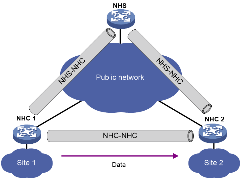
· Full-mesh network—As shown in Figure 1, NHCs can establish tunnels between each other for direct communication. The NHS acts as the routing information exchange center.
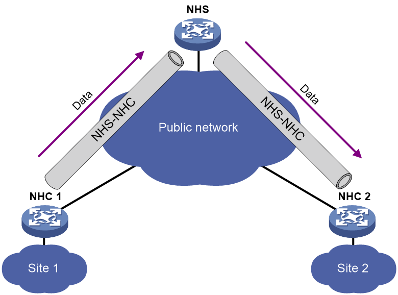
· Hub-spoke network—Also called an NHS-NHC network. As shown in Figure 2, NHCs cannot establish tunnels between each other. Instead, they establish tunnels with the NHS. The NHS forwards data for the NHCs. The NHS acts as both the routing information exchange center and the data forwarding center.
mGRE operation procedure
The mGRE operation includes the following phases:
· Registration.
· Tunnel establishment.
· Route learning and packet forwarding.
Registration
As shown in Figure 3, the registration process is as follows:
1. The NHC sends a registration request to the NHS.
A registration request contains an NHC's public address, private address, connected private subnet, NHRP packet authentication key, and GRE key.
2. After the NHS receives the request, it performs the NHRP packet authentication key and GRE key matching. If both keys are matched, registration succeeds. The NHS sends a registration success message to the NHC.

Tunnel establishment
An mGRE tunnel is established as follows:
· NHC-NHS tunnel establishment process:
An NHC-NHS tunnel is established in the registration process. During registration, the NHC-NHS tunnel is in initialization state. After registration succeeds, the NHC-NHS tunnel is established.
An NHC-NHS tunnel is permanent. An NHC can establish permanent tunnels to any number of NHSs.
· NHC-NHC tunnel establishment process:
a. In a full-mesh network, when an NHC receives a data packet but finds no tunnel for forwarding the packet, the NHC (initiator) sends an address resolution request to the NHS.
b. After receiving the request, the NHS looks up the local NHRP mapping table to find the peer NHC (responder) and forwards the request to the peer NHC.
c. After receiving the request, the peer NHC creates a temporary tunnel and sends an address resolution response to the initiator.
An NHC-NHC tunnel is dynamic. If no data is exchanged within the NHC-NHC tunnel idle timeout, the tunnel will be deleted.
An NHC-NHC tunnel can traverse a NAT gateway. The tunnel can be established when the tunnel initiator, receiver, or both ends reside behind the NAT gateway.
Route learning and packet forwarding
mGRE nodes learn private routes by using dynamic routing protocols.
Dynamic routing must be configured for all private networks and mGRE tunnel interfaces to ensure IP connectivity among the private networks. From the perspective of private networks, an mGRE tunnel is a link that connects different private networks. A dynamic routing protocol discovers neighbors and updates routes over mGRE tunnels, and establishes a routing table.
When an NHC receives a packet destined for a remote private network, it performs the following operations:
1. Searches the routing table for the next hop address to the target private network.
2. Looks up the local NHRP mapping table to obtain the public address that corresponds to the next hop address.
3. Uses the public address as the tunnel destination address to encapsulate the packet.
4. Sends the encapsulated packet to the peer NHC over the mGRE tunnel.
Restrictions: Hardware compatibility with mGRE
|
Hardware |
mGRE compatibility |
|
MSR810, MSR810-W, MSR810-W-DB, MSR810-LM, MSR810-W-LM, MSR810-10-PoE, MSR810-LM-HK, MSR810-W-LM-HK, MSR810-LM-CNDE-SJK, MSR810-CNDE-SJK |
Yes |
|
MSR810-LMS, MSR810-LUS |
Yes |
|
MSR810-LMS-EA, MSR810-LME |
Yes |
|
MSR1004S-5G |
Yes |
|
MSR2600-6-X1, MSR2600-10-X1, MSR2600-15-X1 |
Yes |
|
MSR 2630 |
Yes |
|
MSR3600-28, MSR3600-51 |
Yes |
|
MSR3600-28-SI, MSR3600-51-SI |
No |
|
MSR3600-28-X1, MSR3600-28-X1-DP, MSR3600-51-X1, MSR3600-51-X1-DP |
Yes |
|
MSR3610-I-DP, MSR3610-IE-DP, MSR3610-IE-ES, MSR3610-IE-EAD, MSR-EAD-AK770, MSR3610-I-IG, MSR3610-IE-IG |
Yes |
|
MSR3610-X1, MSR3610-X1-DP, MSR3610-X1-DC, MSR3610-X1-DP-DC, MSR3620-X1, MSR3640-X1 |
Yes |
|
MSR 3610, MSR 3620, MSR 3620-DP, MSR 3640, MSR 3660 |
Yes |
|
MSR3610-G, MSR3620-G |
Yes |
|
MSR3640-X1-HI |
Yes |
|
Hardware |
mGRE compatibility |
|
MSR810-W-WiNet, MSR810-LM-WiNet |
Yes |
|
MSR830-4LM-WiNet |
Yes |
|
MSR830-5BEI-WiNet, MSR830-6EI-WiNet, MSR830-10BEI-WiNet |
Yes |
|
MSR830-6BHI-WiNet, MSR830-10BHI-WiNet |
Yes |
|
MSR2600-6-WiNet, MSR2600-10-X1-WiNet |
Yes |
|
MSR2630-WiNet |
Yes |
|
MSR3600-28-WiNet |
Yes |
|
MSR3610-X1-WiNet |
Yes |
|
MSR3610-WiNet, MSR3620-10-WiNet, MSR3620-DP-WiNet, MSR3620-WiNet, MSR3660-WiNet |
Yes |
|
Hardware |
mGRE compatibility |
|
MSR2630-XS |
Yes |
|
MSR3600-28-XS |
Yes |
|
MSR3610-XS |
Yes |
|
MSR3620-XS |
Yes |
|
MSR3610-I-XS |
Yes |
|
MSR3610-IE-XS |
Yes |
|
MSR3620-X1-XS |
Yes |
|
MSR3640-XS |
Yes |
|
MSR3660-XS |
Yes |
|
Hardware |
mGRE compatibility |
|
MSR810-LM-GL |
Yes |
|
MSR810-W-LM-GL |
Yes |
|
MSR830-6EI-GL |
Yes |
|
MSR830-10EI-GL |
Yes |
|
MSR830-6HI-GL |
Yes |
|
MSR830-10HI-GL |
Yes |
|
MSR1004S-5G-GL |
Yes |
|
MSR2600-6-X1-GL |
Yes |
|
MSR3600-28-SI-GL |
No |
Restrictions and guidelines: mGRE configuration
To set up an mGRE network, first configure the NHSs and then the NHCs.
The device can act only as an NHC. It cannot act as an NHS.
mGRE tasks at a glance
To configure mGRE, perform the following tasks:
7. (Optional.) Configuring IPsec for an mGRE tunnel
Configuring an mGRE tunnel
Restrictions and guidelines
The public address of an NHC can be statically configured or dynamically assigned. The private address of an NHC must be statically configured.
You must configure the same GRE key or configure no key on both ends of a tunnel.
On the device, you must configure different GRE keys for mGRE tunnel interfaces that have the same source address or source interface.
For more information about the GRE key and tunnel interfaces, see GRE and tunneling configuration in Layer 3—IP Services Configuration Guide.
Procedure
1. Enter system view.
system-view
2. Create an mGRE tunnel interface and enter its view.
interface tunnel number mode mgre
3. Configure a private address for the tunnel interface.
ip address ip-address { mask | mask-length } [ sub ]
By default, no private address is configured for a tunnel interface.
4. Configure a source address or source interface for the tunnel interface.
source { ip-address | interface-type interface-number }
By default, no source address or source interface is configured for a tunnel interface.
If you specify a source address, it is used as the source IP address of tunneled packets.
If you specify a source interface, the primary IP address of this interface is used as the source IP address of tunneled packets.
5. Configure an NHRP packet authentication key.
nhrp authentication { cipher | simple } string
By default, no NHRP packet authentication key is configured. NHRP nodes do not authenticate NHRP packets received from each other.
6. Configure an NHRP network ID for the mGRE tunnel.
nhrp network-id number
By default, an mGRE tunnel does not have an NHRP network ID.
7. Configure the holdtime for NHRP mapping entries.
nhrp holdtime seconds
By default, the holdtime of NHRP mapping entries is 7200 seconds.
After the holdtime expires, the NHC automatically deletes the NHRP mapping entries and re-registers to the NHS.
8. Configure an NHS private-to-public address mapping.
nhrp nhs nhs-address nbma nbma-address
By default, no NHS private-to-public address mappings are configured.
9. (Optional.) Configure a GRE key for the tunnel interface.
gre key key
By default, no GRE key is configured for an mGRE tunnel interface.
10. (Optional.) Set the DF bit for tunneled packets.
tunnel dfbit enable
By default, the DF bit is not set. Tunneled packets can be fragmented for forwarding.
Configuring routing
NHCs support dynamic routing protocols of OSPF, RIP, and BGP.
When you configure routing for mGRE client, following these restrictions and guidelines:
|
Network type |
Routing protocols |
Remarks |
|
Full-mesh network |
RIP |
Not supported. |
|
OSPF |
You must specify the OSPF interface network type as broadcast. |
|
|
BGP |
You need to configure routing policies. Ensure that the local NHC learns a route to the remote private network, and the route's next hop address is the address of the remote NHC. |
|
|
NHS-NHC network |
RIP |
You must use the RIP-2 multicast mode and disable the split horizon feature for NHS nodes |
|
OSPF |
You must specify the OSPF interface network type as p2mp. |
|
|
BGP |
You need to configure routing policies. Ensure that the local NHC learns a route to the remote private network, and the route's next hop address is the address of the NHS. |
For more information about the routing protocols and routing policy configuration, see RIP, OSPF, BGP, and routing policy in Layer 3—IP Routing Configuration Guide.
Configuring IPsec for an mGRE tunnel
The device supports protecting mGRE tunnel data and control packets by using IPsec profiles.
To configure IPsec for an mGRE tunnel:
11. Configure an IPsec transform set to specify the security protocol, authentication and encryption algorithms, and encapsulation mode.
12. Configure an IKE-based IPsec profile.
13. Apply the IKE-based IPsec profile to the mGRE tunnel interface.
For more information about IPsec configuration, see "Configuring IPsec."
Display and maintenance commands for mGRE
Execute display commands in any view and reset commands in user view.
|
Task |
Command |
|
Display mGRE session information. |
display mgre session [ interface tunnel interface-number [ peer ipv4-address ] ] [ verbose ] |
|
Display information about NHRP mapping entries. |
display nhrp map [ interface tunnel interface-number [ peer ipv4-address ] ] [ verbose ] |
|
Display NHRP packet statistics for tunnel interfaces. |
display nhrp statistics [ interface tunnel interface-number ] |
|
Reset mGRE sessions. |
reset mgre session [ interface tunnel interface-number [ peer ipv4-address ] ] |
|
Clear mGRE session statistics. |
reset mgre statistics [ interface tunnel interface-number [ peer ipv4-address ] ] |
|
Clear NHRP packet statistics for tunnel interfaces. |
reset nhrp statistics [ interface tunnel interface-number ] |
mGRE configuration examples
Example: Configuring a full-mesh mGRE network
Network configuration
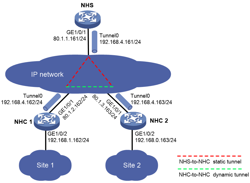
As shown in Figure 4, construct a full-mesh mGRE network. The NHS manages and maintains information for each node.
Set up permanent (static) mGRE tunnels between the NHS and NHCs. Set up temporary (dynamic) mGRE tunnels between NHCs when they need to communicate with each other.
Procedure
1. Configure NHC 1:
# Configure an IP address for GigabitEthernet 1/0/1.
<NHC1> system-view
[NHC1] interface gigabitethernet 1/0/1
[NHC1-GigabitEthernet1/0/1] ip address 80.1.2.162 255.255.255.0
[NHC1-GigabitEthernet1/0/1] quit
# Configure an IP address for GigabitEthernet 1/0/2.
[NHC1] interface gigabitethernet 1/0/2
[NHC1-GigabitEthernet1/0/2] ip address 192.168.1.162 255.255.255.0
[NHC1-GigabitEthernet1/0/2] quit
# Configure an IP address for mGRE tunnel interface Tunnel0.
[NHC1] interface tunnel0 mode mgre
[NHC1-Tunnel0] ip address 192.168.4.162 255.255.255.0
# Specify the OSPF interface network type as broadcast.
[NHC1-Tunnel0] ospf network-type broadcast
# Enable OSPF for the tunnel interface.
[NHC1-Tunnel0] ospf 1 area 0.0.0.1
# Specify GigabitEthernet 1/0/1 as the source interface of the mGRE tunnel.
[NHC1-Tunnel0] source gigabitethernet 1/0/1
# Set the GRE key to 100000.
[NHC1-Tunnel0] gre key 100000
# Set the NHRP network ID to 9.
[NHC1-Tunnel0] nhrp network-id 9
# Configure the NHRP packet authentication key as a plaintext string of 12345678.
[NHC1-Tunnel0] nhrp authentication simple 12345678
# Set the holdtime of NHRP mapping entries to 3600 seconds.
[NHC1-Tunnel0] nhrp holdtime 3600
# Configure an NHS private-to-public address mapping.
[NHC1-Tunnel0] nhrp nhs 192.168.4.161 nbma 80.1.1.161
[NHC1-Tunnel0] quit
# Configure basic OSPF.
[NHC1] ospf 1
[NHC1-ospf-1] area 0.0.0.1
[NHC1-ospf-1-area-0.0.0.1] network 192.168.4.0 0.0.0.255
[NHC1-ospf-1-area-0.0.0.1] network 192.168.1.0 0.0.0.255
[NHC1-ospf-1-area-0.0.0.1] quit
2. Configure NHC 2:
# Configure an IP address for GigabitEthernet 1/0/1.
<NHC2> system-view
[NHC2] interface gigabitethernet 1/0/1
[NHC2-GigabitEthernet1/0/1] ip address 80.1.3.163 255.255.255.0
[NHC2-GigabitEthernet1/0/1] quit
# Configure an IP address for GigabitEthernet 1/0/2.
[NHC2] interface gigabitethernet 1/0/2
[NHC2-GigabitEthernet1/0/2] ip address 192.168.0.163 255.255.255.0
[NHC2-GigabitEthernet1/0/2] quit
# Configure an IP address for mGRE tunnel interface Tunnel0.
[NHC2] interface tunnel0 mode mgre
[NHC2-Tunnel0] ip address 192.168.4.163 255.255.255.0
# Specify the OSPF interface network type as broadcast.
[NHC2-Tunnel0] ospf network-type broadcast
# Enable OSPF for the tunnel interface.
[NHC2-Tunnel0] ospf 1 area 0.0.0.1
# Specify GigabitEthernet 1/0/1 as the source interface of the mGRE tunnel.
[NHC2-Tunnel0] source gigabitethernet 1/0/1
# Set the GRE key to 100000.
[NHC2-Tunnel0] gre key 100000
# Set the NHRP network ID to 9.
[NHC2-Tunnel0] nhrp network-id 9
# Configure the NHRP packet authentication key as a plaintext string of 12345678.
[NHC2-Tunnel0] nhrp authentication simple 12345678
# Set the holdtime of NHRP mapping entries to 3600 seconds.
[NHC2-Tunnel0] nhrp holdtime 3600
# Configure an NHS private-to-public address mapping.
[NHC2-Tunnel0] nhrp nhs 192.168.4.161 nbma 80.1.1.161
[NHC2-Tunnel0] quit
# Configure basic OSPF.
[NHC2] ospf 1
[NHC2-ospf-1] area 0.0.0.1
[NHC2-ospf-1-area-0.0.0.1] network 192.168.4.0 0.0.0.255
[NHC2-ospf-1-area-0.0.0.1] network 192.168.0.0 0.0.0.255
[NHC2-ospf-1-area-0.0.0.1] quit
Verifying the configuration
# Display detailed information about the NHRP mapping table on NHC 1.
[NHC1] display nhrp map verbose
Interface : Tunnel0
Destination/mask : 192.168.4.161/24
Next hop : 192.168.4.161
Creation time : 00:11:21
Expiration time : never expire
Type : static
Flags : up
NBMA address : 80.1.1.161
# Display brief information about the mGRE session on NHC 1.
[NHC1] display mgre session
Interface : Tunnel0
Number of sessions: 1
Peer NBMA address Peer protocol address Type State State duration
80.1.1.161 192.168.4.161 C-S Succeeded 00:09:42
The output indicates that NHC 1 has established a permanent tunnel with the NHS. The output on NHC 2 is similar.
# Ping the private address 192.168.4.163 of NHC 2 from NHC 1.
[NHC1] ping 192.168.4.163
Ping 192.168.4.163 (192.168.4.163): 56 data bytes, press CTRL_C to break
56 bytes from 192.168.4.163: icmp_seq=0 ttl=255 time=3.314 ms
56 bytes from 192.168.4.163: icmp_seq=1 ttl=255 time=2.786 ms
56 bytes from 192.168.4.163: icmp_seq=2 ttl=255 time=2.317 ms
56 bytes from 192.168.4.163: icmp_seq=3 ttl=255 time=3.060 ms
56 bytes from 192.168.4.163: icmp_seq=4 ttl=255 time=2.258 ms
--- Ping statistics for 192.168.4.163 ---
5 packets transmitted, 5 packets received, 0.0% packet loss
round-trip min/avg/max/std-dev = 2.258/2.747/3.314/0.411 ms
# Display detailed information about the NHRP mapping table on NHC 1.
[NHC1] display nhrp map verbose
Interface : Tunnel0
Destination/mask : 192.168.4.161/24
Next hop : 192.168.4.161
Creation time : 01:10:25
Expiration time : never expire
Type : static
Flags : up
NBMA address : 80.1.1.161
Interface : Tunnel0
Destination/mask : 192.168.4.163/32
Next hop : 192.168.4.163
Creation time : 00:00:24
Expiration time : 00:01:36
Type : cached
Flags : used up
NBMA address : 80.1.3.163
# Display brief information about the mGRE session on NHC 1.
[NHC1] display mgre session
Interface : Tunnel0
Number of sessions: 2
Peer NBMA address Peer protocol address Type State State duration
80.1.1.161 192.168.4.161 C-S Succeeded 00:10:28
80.1.3.163 192.168.4.163 C-C Succeeded 00:00:32
The output indicates that NHC 1 has established a permanent tunnel with the NHS and a temporary tunnel with NHC 2. The output on NHC 2 is similar.
Example: Configuring an NHS-NHC mGRE network
Network configuration
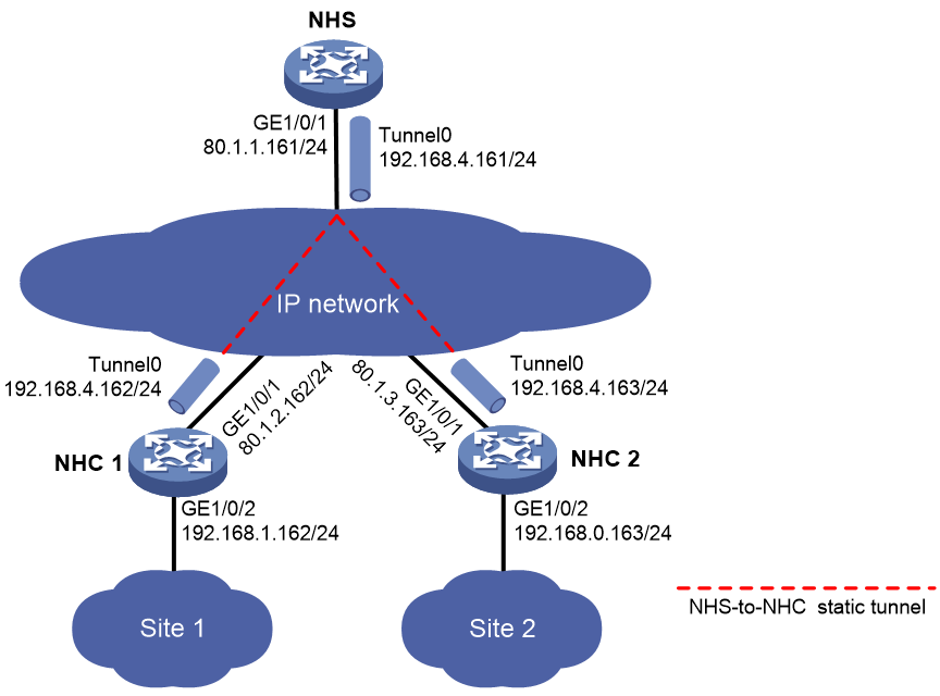
As shown in Figure 5, construct an NHC-NHS mGRE network. The NHS manages and maintains information for each node and forwards packets between NHCs.
Set up permanent (static) mGRE tunnels between the NHS and NHCs.

Procedure
1. Configure NHC 1:
# Configure an IP address for GigabitEthernet 1/0/1.
<NHC1> system-view
[NHC1] interface gigabitethernet 1/0/1
[NHC1-GigabitEthernet1/0/1] ip address 80.1.2.162 255.255.255.0
[NHC1-GigabitEthernet1/0/1] quit
# Configure an IP address for GigabitEthernet 1/0/2.
[NHC1] interface gigabitethernet 1/0/2
[NHC1-GigabitEthernet1/0/2] ip address 192.168.1.162 255.255.255.0
[NHC1-GigabitEthernet1/0/2] quit
# Configure an IP address for mGRE tunnel interface Tunnel0.
[NHC1] interface tunnel0 mode mgre
[NHC1-Tunnel0] ip address 192.168.4.162 255.255.255.0
# Specify the OSPF interface network type as P2MP.
[NHC1-Tunnel0] ospf network-type p2mp
# Enable OSPF for the tunnel interface.
[NHC1-Tunnel0] ospf 1 area 0.0.0.1
# Specify GigabitEthernet 1/0/1 as the source interface of the mGRE tunnel.
[NHC1-Tunnel0] source gigabitethernet 1/0/1
# Set the GRE key to 100000.
[NHC1-Tunnel0] gre key 100000
# Set the NHRP network ID to 9.
[NHC1-Tunnel0] nhrp network-id 9
# Configure the NHRP packet authentication key as a plaintext string of 12345678.
[NHC1-Tunnel0] nhrp authentication simple 12345678
# Set the holdtime of NHRP mapping entries to 3600 seconds.
[NHC1-Tunnel0] nhrp holdtime 3600
# Configure an NHS private-to-public address mapping.
[NHC1-Tunnel0] nhrp nhs 192.168.4.161 nbma 80.1.1.161
[NHC1-Tunnel0] quit
# Configure basic OSPF.
[NHC1] ospf 1
[NHC1-ospf-1] area 0.0.0.1
[NHC1-ospf-1-area-0.0.0.1] network 192.168.4.0 0.0.0.255
[NHC1-ospf-1-area-0.0.0.1] network 192.168.1.0 0.0.0.255
[NHC1-ospf-1-area-0.0.0.1] quit
2. Configure NHC 2:
# Configure an IP address for GigabitEthernet 1/0/1.
<NHC2> system-view
[NHC2] interface gigabitethernet 1/0/1
[NHC2-GigabitEthernet1/0/1] ip address 80.1.3.163 255.255.255.0
[NHC2-GigabitEthernet1/0/1] quit
# Configure an IP address for GigabitEthernet 1/0/2.
[NHC2] interface gigabitethernet 1/0/2
[NHC2-GigabitEthernet1/0/2] ip address 192.168.0.163 255.255.255.0
[NHC2-GigabitEthernet1/0/2] quit
# Configure an IP address for mGRE tunnel interface Tunnel0.
[NHC2] interface tunnel0 mode mgre
[NHC2-Tunnel0] ip address 192.168.4.163 255.255.255.0
# Specify the OSPF interface network type as P2MP.
[NHC2-Tunnel0] ospf network-type p2mp
# Enable OSPF for the tunnel interface.
[NHC2-Tunnel0] ospf 1 area 0.0.0.1
# Specify GigabitEthernet 1/0/1 as the source interface of the mGRE tunnel.
[NHC2-Tunnel0] source gigabitethernet 1/0/1
# Set the GRE key to 100000.
[NHC2-Tunnel0] gre key 100000
# Set the NHRP network ID to 9.
[NHC2-Tunnel0] nhrp network-id 9
# Configure the NHRP packet authentication key as a plaintext string of 12345678.
[NHC2-Tunnel0] nhrp authentication simple 12345678
# Set the holdtime of NHRP mapping entries to 3600 seconds.
[NHC2-Tunnel0] nhrp holdtime 3600
# Configure an NHS private-to-public address mapping.
[NHC2-Tunnel0] nhrp nhs 192.168.4.161 nbma 80.1.1.161
[NHC2-Tunnel0] quit
# Configure basic OSPF.
[NHC2] ospf 1
[NHC2-ospf-1] area 0.0.0.1
[NHC2-ospf-1-area-0.0.0.1] network 192.168.4.0 0.0.0.255
[NHC2-ospf-1-area-0.0.0.1] network 192.168.0.0 0.0.0.255
[NHC2-ospf-1-area-0.0.0.1] quit
Verifying the configuration
# Display detailed information about the NHRP mapping table on NHC 1.
[NHC1] display nhrp map verbose
Interface : Tunnel0
Destination/mask : 192.168.4.161/24
Next hop : 192.168.4.161
Creation time : 07:50:32
Expiration time : never expire
Type : static
Flags : up
NBMA address : 80.1.1.161
# Display brief information about the mGRE session on NHC 1.
[NHC1] display mgre session
Interface : Tunnel0
Number of sessions: 1
Peer NBMA address Peer protocol address Type State State duration
80.1.1.161 192.168.4.161 C-S Succeeded 07:49:14
The output indicates that NHC 1 has established a permanent tunnel with the NHS. The output on NHC 2 is similar.
# On NHC 1, ping Site 1 and Site 2. The ping operation succeeds.
[NHC1] ping -a 192.168.1.162 192.168.0.163
Ping 192.168.0.163 (192.168.0.163) from 192.168.1.162: 56 data bytes, press CTRL_C to break
56 bytes from 192.168.0.163: icmp_seq=0 ttl=254 time=10.000 ms
56 bytes from 192.168.0.163: icmp_seq=1 ttl=254 time=17.000 ms
56 bytes from 192.168.0.163: icmp_seq=2 ttl=254 time=14.000 ms
56 bytes from 192.168.0.163: icmp_seq=3 ttl=254 time=7.000 ms
56 bytes from 192.168.0.163: icmp_seq=4 ttl=254 time=7.000 ms
--- Ping statistics for 192.168.0.163 ---
5 packets transmitted, 5 packets received, 0.0% packet loss
round-trip min/avg/max/std-dev = 7.000/11.000/17.000/3.950 ms
Example: Configuring an IPsec-protected full-mesh mGRE network
Network configuration
As shown in Figure 6, construct a full-mesh mGRE network. The NHS manages and maintains information for each node.
Set up permanent (static) mGRE tunnels between the NHS and NHCs. Set up temporary (dynamic) mGRE tunnels between NHCs when they need to communicate with each other.
Configure IPsec to protect the mGRE tunnels.

Procedure
1. Configure NHC 1:
# Configure an IP address for GigabitEthernet 1/0/1.
<NHC1> system-view
[NHC1] interface gigabitethernet 1/0/1
[NHC1-GigabitEthernet1/0/1] ip address 80.1.2.162 255.255.255.0
[NHC1-GigabitEthernet1/0/1] quit
# Configure an IP address for GigabitEthernet 1/0/2.
[NHC1] interface gigabitethernet 1/0/2
[NHC1-GigabitEthernet1/0/2] ip address 192.168.1.162 255.255.255.0
[NHC1-GigabitEthernet1/0/2] quit
# Configure an IP address for mGRE tunnel interface Tunnel0.
[NHC1] interface tunnel0 mode mgre
[NHC1-Tunnel0] ip address 192.168.4.162 255.255.255.0
# Specify the OSPF interface network type as broadcast.
[NHC1-Tunnel0] ospf network-type broadcast
# Set the OSPF interface DR priority to 0.
[NHC1-Tunnel0] ospf dr-priority 0
# Enable OSPF for the tunnel interface.
[NHC1-Tunnel0] ospf 1 area 0.0.0.1
# Specify GigabitEthernet 1/0/1 as the source interface of the mGRE tunnel.
[NHC1-Tunnel0] source gigabitethernet 1/0/1
# Set the GRE key to 100000.
[NHC1-Tunnel0] gre key 100000
# Set the NHRP network ID to 9.
[NHC1-Tunnel0] nhrp network-id 9
# Configure the NHRP packet authentication key as a plaintext string of 12345678.
[NHC1-Tunnel0] nhrp authentication simple 12345678
# Set the holdtime of NHRP mapping entries to 3600 seconds.
[NHC1-Tunnel0] nhrp holdtime 3600
# Configure an NHS private-to-public address mapping.
[NHC1-Tunnel0] nhrp nhs 192.168.4.161 nbma 80.1.1.161
[NHC1-Tunnel0] quit
# Configure basic OSPF.
[NHC1] ospf 1
[NHC1-ospf-1] area 0.0.0.1
[NHC1-ospf-1-area-0.0.0.1] network 192.168.4.0 0.0.0.255
[NHC1-ospf-1-area-0.0.0.1] network 192.168.1.0 0.0.0.255
[NHC1-ospf-1-area-0.0.0.1] quit
# Configure an IPsec transform set named aa. Specify the encryption algorithm as 56-bit DES and authentication algorithm as HMAC-SHA1.
[NHC1] ipsec transform-set aa
[NHC1-ipsec-transform-set-aa] esp encryption-algorithm des-cbc
[NHC1-ipsec-transform-set-aa] esp authentication-algorithm sha1
[NHC1-ipsec-transform-set-aa] quit
# Create IKE keychain 1.
[NHC1] ike keychain 1
# Configure the pre-shared key used with the peer 80.1.1.161 as a plaintext string of 12345678.
[NHC1-ike-keychain-1] pre-shared-key address 80.1.1.161 24 key simple 12345678
# Configure the pre-shared key used with the peer 80.1.3.163 as a plaintext string of 12345678.
[NHC1-ike-keychain-1] pre-shared-key address 80.1.3.163 24 key simple 12345678
[NHC1-ike-keychain-1] quit
# Create an IKE profile named abc.
[NHC1] ike profile abc
# Specify IKE keychain 1 for the IKE profile.
[NHC1-ike-profile-abc] keychain 1
[NHC1-ike-profile-abc] quit
# Create an IKE-based IPsec profile named abc.
[NHC1] ipsec profile abc isakmp
# Specify IPsec transform set aa for the IPsec profile.
[NHC1-ipsec-profile-isakmp-abc] transform-set aa
# Specify IKE profile abc for the IPsec profile.
[NHC1-ipsec-profile-isakmp-abc] ike-profile abc
[NHC1-ipsec-profile-isakmp-abc] quit
# Apply IPsec profile abc to the mGRE tunnel interface.
[NHC1] interface tunnel0 mode mgre
[NHC1-Tunnel0] tunnel protection ipsec profile abc
[NHC1-Tunnel0] quit
2. Configure NHC 2:
# Configure an IP address for GigabitEthernet 1/0/1.
<NHC2> system-view
[NHC2] interface gigabitethernet 1/0/1
[NHC2-GigabitEthernet1/0/1] ip address 80.1.3.163 255.255.255.0
[NHC2-GigabitEthernet1/0/1] quit
# Configure an IP address for GigabitEthernet 1/0/2.
[NHC2] interface gigabitethernet 1/0/2
[NHC2-GigabitEthernet1/0/2] ip address 192.168.0.163 255.255.255.0
[NHC2-GigabitEthernet1/0/2] quit
# Configure an IP address for mGRE tunnel interface Tunnel0.
[NHC2] interface tunnel0 mode mgre
[NHC2-Tunnel0] ip address 192.168.4.163 255.255.255.0
# Specify the OSPF interface network type as broadcast.
[NHC2-Tunnel0] ospf network-type broadcast
# Set the OSPF interface DR priority to 0.
[NHC2-Tunnel0] ospf dr-priority 0
# Enable OSPF for the tunnel interface.
[NHC2-Tunnel0] ospf 1 area 0.0.0.1
# Specify GigabitEthernet 1/0/1 as the source interface of the mGRE tunnel.
[NHC2-Tunnel0] source gigabitethernet 1/0/1
# Set the GRE key to 100000.
[NHC2-Tunnel0] gre key 100000
# Set the NHRP network ID to 9.
[NHC2-Tunnel0] nhrp network-id 9
# Configure the NHRP packet authentication key as a plaintext string of 12345678.
[NHC2-Tunnel0] nhrp authentication simple 12345678
# Set the holdtime of NHRP mapping entries to 3600 seconds.
[NHC2-Tunnel0] nhrp holdtime 3600
# Configure an NHS private-to-public address mapping.
[NHC2-Tunnel0] nhrp nhs 192.168.4.161 nbma 80.1.1.161
[NHC2-Tunnel0] quit
# Configure basic OSPF.
[NHC2] ospf 1
[NHC2-ospf-1] area 0.0.0.1
[NHC2-ospf-1-area-0.0.0.1] network 192.168.4.0 0.0.0.255
[NHC2-ospf-1-area-0.0.0.1] network 192.168.0.0 0.0.0.255
[NHC2-ospf-1-area-0.0.0.1] quit
# Configure an IPsec transform set named aa. Specify the encryption algorithm as 56-bit DES and authentication algorithm as HMAC-SHA1.
[NHC2] ipsec transform-set aa
[NHC2-ipsec-transform-set-aa] esp encryption-algorithm des-cbc
[NHC2-ipsec-transform-set-aa] esp authentication-algorithm sha1
[NHC2-ipsec-transform-set-aa] quit
# Create IKE keychain 1.
[NHC2] ike keychain 1
# Configure the pre-shared key used with the peer 80.1.1.161 as a plaintext string of 12345678.
[NHC2-ike-keychain-1] pre-shared-key address 80.1.1.161 24 key simple 12345678
# Configure the pre-shared key used with the peer 80.1.2.162 as a plaintext string of 12345678.
[NHC2-ike-keychain-1] pre-shared-key address 80.1.2.162 24 key simple 12345678
[NHC2-ike-keychain-1] quit
# Create an IKE profile named abc.
[NHC2] ike profile abc
# Specify IKE keychain 1 for the IKE profile.
[NHC2-ike-profile-abc] keychain 1
[NHC2-ike-profile-abc] quit
# Create an IKE-based IPsec profile named abc.
[NHC2] ipsec profile abc isakmp
# Specify IPsec transform set aa for the IPsec profile.
[NHC2-ipsec-profile-isakmp-abc] transform-set aa
# Specify IKE profile abc for the IPsec profile.
[NHC2-ipsec-profile-isakmp-abc] ike-profile abc
[NHC2-ipsec-profile-isakmp-abc] quit
# Apply IPsec profile abc to the mGRE tunnel interface.
[NHC2] interface tunnel0 mode mgre
[NHC2-Tunnel0] tunnel protection ipsec profile abc
[NHC2-Tunnel0] quit
Verifying the configuration
# Display detailed information about the NHRP mapping table on NHC 1.
[NHC1] display nhrp map verbose
Interface : Tunnel0
Destination/mask : 192.168.4.161/24
Next hop : 192.168.4.161
Creation time : 00:30:51
Expiration time : never expire
Type : static
Flags : up ipsec
NBMA address : 80.1.1.161
# Display brief information about the mGRE session on NHC 1.
[NHC1] display mgre session
Interface : Tunnel0
Number of sessions: 1
Peer NBMA address Peer protocol address Type State State duration
80.1.1.161 192.168.4.161 C-S Succeeded 00:09:42
The output indicates that NHC 1 has established a permanent tunnel with the NHS. The output on NHC 2 is similar.
# Ping the private address 192.168.4.163 of NHC 2 from NHC 1.
[NHC1] ping 192.168.4.163
Ping 192.168.4.163 (192.168.4.163): 56 data bytes, press CTRL_C to break
56 bytes from 192.168.4.163: icmp_seq=0 ttl=255 time=3.314 ms
56 bytes from 192.168.4.163: icmp_seq=1 ttl=255 time=2.786 ms
56 bytes from 192.168.4.163: icmp_seq=2 ttl=255 time=2.317 ms
56 bytes from 192.168.4.163: icmp_seq=3 ttl=255 time=3.060 ms
56 bytes from 192.168.4.163: icmp_seq=4 ttl=255 time=2.258 ms
--- Ping statistics for 192.168.4.163 ---
5 packets transmitted, 5 packets received, 0.0% packet loss
round-trip min/avg/max/std-dev = 2.258/2.747/3.314/0.411 ms
# Display detailed information about the NHRP mapping table on NHC 1.
[NHC1] display nhrp map verbose
Interface : Tunnel0
Destination/mask : 192.168.4.161/24
Next hop : 192.168.4.161
Creation time : 01:10:25
Expiration time : never expire
Type : static
Flags : up ipsec
NBMA address : 80.1.1.161
Interface : Tunnel0
Destination/mask : 192.168.4.163/32
Next hop : 192.168.4.163
Creation time : 00:00:24
Expiration time : 00:01:36
Type : cached
Flags : used up ipsec
NBMA address : 80.1.3.163
# Display brief information about the mGRE session on NHC 1.
[NHC1] display mgre session
Interface : Tunnel0
Number of sessions: 2
Peer NBMA address Peer protocol address Type State State duration
80.1.1.161 192.168.4.161 C-S Succeeded 00:10:28
80.1.3.163 192.168.4.163 C-C Succeeded 00:00:32
The output indicates that NHC 1 has established a permanent tunnel with the NHS and a temporary tunnel with NHC 2. Both tunnels are protected by IPsec. The output on NHC 2 is similar.
# Display IKE SA information on NHC 1. The output on NHC 2 is similar.
[NHC1] display ike sa
Connection-ID Remote Flag DOI
------------------------------------------------------------------
240 80.1.1.161 RD IPsec
241 80.1.3.163 RD IPsec
Flags:
RD--READY RL--REPLACED FD-FADING
# Display IPsec SA information on NHC 1. The output on NHC 2 is similar.
[NHC1] display ipsec sa
-------------------------------
Interface: Tunnel0
-------------------------------
-----------------------------
IPsec profile: abc
Mode: ISAKMP
-----------------------------
Tunnel id: 4
Encapsulation mode: tunnel
Perfect forward secrecy:
Path MTU: 1398
Tunnel:
local address: 80.1.2.162
remote address: 80.1.3.163
Flow:
sour addr: 80.1.2.162/255.255.255.255 port: 0 protocol: gre
dest addr: 80.1.3.163/255.255.255.255 port: 0 protocol: gre
[Inbound ESP SAs]
SPI: 1566691874 (0x5d61d222)
Connection ID: 21474836488
Transform set: ESP-ENCRYPT-DES-CBC ESP-AUTH-SHA1
SA duration (kilobytes/sec): 1843200/3600
SA remaining duration (kilobytes/sec): 1843200/3584
Max received sequence-number: 0
Anti-replay check enable: Y
Anti-replay window size: 64
UDP encapsulation used for NAT traversal: N
Status: Active
[Outbound ESP SAs]
SPI: 1199855674 (0x4784583a)
Connection ID: 12884901895
Transform set: ESP-ENCRYPT-DES-CBC ESP-AUTH-SHA1
SA duration (kilobytes/sec): 1843200/3600
SA remaining duration (kilobytes/sec): 1843199/3584
Max sent sequence-number: 4
UDP encapsulation used for NAT traversal: N
Status: Active
-----------------------------
IPsec profile: abc
Mode: ISAKMP
-----------------------------
Tunnel id: 5
Encapsulation mode: tunnel
Perfect forward secrecy:
Path MTU: 1398
Tunnel:
local address: 80.1.2.162
remote address: 80.1.1.161
Flow:
sour addr: 80.1.2.162/255.255.255.255 port: 0 protocol: gre
dest addr: 80.1.1.161/255.255.255.255 port: 0 protocol: gre
[Inbound ESP SAs]
SPI: 989656188 (0x3afcf47c)
Connection ID: 30064771081
Transform set: ESP-ENCRYPT-DES-CBC ESP-AUTH-SHA1
SA duration (kilobytes/sec): 1843200/3600
SA remaining duration (kilobytes/sec): 1843198/3560
Max received sequence-number: 12
Anti-replay check enable: Y
Anti-replay window size: 64
UDP encapsulation used for NAT traversal: N
Status: Active
[Outbound ESP SAs]
SPI: 1408141582 (0x53ee890e)
Connection ID: 38654705674
Transform set: ESP-ENCRYPT-DES-CBC ESP-AUTH-SHA1
SA duration (kilobytes/sec): 1843200/3600
SA remaining duration (kilobytes/sec): 1843199/3560
Max sent sequence-number: 8
UDP encapsulation used for NAT traversal: N
Status: Active
Example: Configuring an IPsec-protected NHS-NHC mGRE network
Network configuration
As shown in Figure 7, construct an NHS-NHC mGRE network. The NHS manages and maintains information for each node and forwards packets between NHCs.
Set up permanent (static) mGRE tunnels between the NHS and NHCs.
Configure IPsec to protect the mGRE tunnels.
Procedure
1. Configure NHC 1:
# Configure an IP address for GigabitEthernet 1/0/1.
<NHC1> system-view
[NHC1] interface gigabitethernet 1/0/1
[NHC1-GigabitEthernet1/0/1] ip address 80.1.2.162 255.255.255.0
[NHC1-GigabitEthernet1/0/1] quit
# Configure an IP address for GigabitEthernet 1/0/2.
[NHC1] interface gigabitethernet 1/0/2
[NHC1-GigabitEthernet1/0/2] ip address 192.168.1.162 255.255.255.0
[NHC1-GigabitEthernet1/0/2] quit
# Configure an IP address for mGRE tunnel interface Tunnel0.
[NHC1] interface tunnel0 mode mgre
[NHC1-Tunnel0] ip address 192.168.4.162 255.255.255.0
# Specify the OSPF interface network type as P2MP.
[NHC1-Tunnel0] ospf network p2mp
# Enable OSPF for the tunnel interface.
[NHC1-Tunnel0] ospf 1 area 0.0.0.1
# Specify GigabitEthernet 1/0/1 as the source interface of the mGRE tunnel.
[NHC1-Tunnel0] source gigabitethernet 1/0/1
# Set the GRE key to 100000.
[NHC1-Tunnel0] gre key 100000
# Set the NHRP network ID to 9.
[NHC1-Tunnel0] nhrp network-id 9
# Configure the NHRP packet authentication key as a plaintext string of 12345678.
[NHC1-Tunnel0] nhrp authentication simple 12345678
# Set the holdtime of NHRP mapping entries to 3600 seconds.
[NHC1-Tunnel0] nhrp holdtime 3600
# Configure an NHS private-to-public address mapping.
[NHC1-Tunnel0] nhrp nhs 192.168.4.161 nbma 80.1.1.161
[NHC1-Tunnel0] quit
# Configure basic OSPF.
[NHC1] ospf 1
[NHC1-ospf-1] area 0.0.0.1
[NHC1-ospf-1-area-0.0.0.1] network 192.168.4.0 0.0.0.255
[NHC1-ospf-1-area-0.0.0.1] network 192.168.1.0 0.0.0.255
[NHC1-ospf-1-area-0.0.0.1] quit
# Configure an IPsec transform set named aa. Specify the encryption algorithm as 56-bit DES and authentication algorithm as HMAC-SHA1.
[NHC1] ipsec transform-set aa
[NHC1-ipsec-transform-set-aa] esp encryption-algorithm des-cbc
[NHC1-ipsec-transform-set-aa] esp authentication-algorithm sha1
[NHC1-ipsec-transform-set-aa] quit
# Create an IKE keychain named 1.
[NHC1] ike keychain 1
# Configure the pre-shared key used with the peer 80.1.1.161 as a plaintext string of 12345678.
[NHC1-ike-keychain-1] pre-shared-key address 80.1.1.161 24 key simple 12345678
# Configure the pre-shared key used with the peer 80.1.3.163 as a plaintext string of 12345678.
[NHC1-ike-keychain-1] pre-shared-key address 80.1.3.163 24 key simple 12345678
[NHC1-ike-keychain-1] quit
# Create an IKE profile named abc.
[NHC1] ike profile abc
# Specify IKE keychain 1 for the IKE profile.
[NHC1-ike-profile-abc] keychain 1
[NHC1-ike-profile-abc] quit
# Create an IKE-based IPsec profile named abc.
[NHC1] ipsec profile abc isakmp
# Specify IPsec transform set aa for the IPsec profile.
[NHC1-ipsec-profile-isakmp-abc] transform-set aa
# Specify IKE profile abc for the IPsec profile.
[NHC1-ipsec-profile-isakmp-abc] ike-profile abc
[NHC1-ipsec-profile-isakmp-abc] quit
# Apply IPsec profile abc to the mGRE tunnel interface.
[NHC1] interface tunnel0 mode mgre
[NHC1-Tunnel0] tunnel protection ipsec profile abc
[NHC1-Tunnel0] quit
2. Configure NHC 2:
# Configure an IP address for GigabitEthernet 1/0/1.
<NHC2> system-view
[NHC2] interface gigabitethernet 1/0/1
[NHC2-GigabitEthernet1/0/1] ip address 80.1.3.163 255.255.255.0
[NHC2-GigabitEthernet1/0/1] quit
# Configure an IP address for GigabitEthernet 1/0/2.
[NHC2] interface gigabitethernet 1/0/2
[NHC2-GigabitEthernet1/0/2] ip address 192.168.0.163 255.255.255.0
[NHC2-GigabitEthernet1/0/2] quit
# Configure an IP address for mGRE tunnel interface Tunnel0.
[NHC2] interface tunnel0 mode mgre
[NHC2-Tunnel0] ip address 192.168.4.163 255.255.255.0
# Specify the OSPF interface network type as P2MP.
[NHC2-Tunnel0] ospf network p2mp
# Enable OSPF for the tunnel interface.
[NHC2-Tunnel0] ospf 1 area 0.0.0.1
# Specify GigabitEthernet 1/0/1 as the source interface of the mGRE tunnel.
[NHC2-Tunnel0] source gigabitethernet 1/0/1
# Set the GRE key to 100000.
[NHC2-Tunnel0] gre key 100000
# Set the NHRP network ID to 9.
[NHC2-Tunnel0] nhrp network-id 9
# Configure the NHRP packet authentication key as a plaintext string of 12345678.
[NHC2-Tunnel0] nhrp authentication simple 12345678
# Set the holdtime of NHRP mapping entries to 3600 seconds.
[NHC2-Tunnel0] nhrp holdtime 3600
# Configure an NHS private-to-public address mapping.
[NHC2-Tunnel0] nhrp nhs 192.168.4.161 nbma 80.1.1.161
[NHC2-Tunnel0] quit
# Configure basic OSPF.
[NHC2] ospf 1
[NHC2-ospf-1] area 0.0.0.1
[NHC2-ospf-1-area-0.0.0.1] network 192.168.4.0 0.0.0.255
[NHC2-ospf-1-area-0.0.0.1] network 192.168.0.0 0.0.0.255
[NHC2-ospf-1-area-0.0.0.1] quit
# Configure an IPsec transform set named aa. Specify the encryption algorithm as 56-bit DES and authentication algorithm as HMAC-SHA1.
[NHC2] ipsec transform-set aa
[NHC2-ipsec-transform-set-aa] esp encryption-algorithm des-cbc
[NHC2-ipsec-transform-set-aa] esp authentication-algorithm sha1
[NHC2-ipsec-transform-set-aa] quit
# Create an IKE keychain named 1.
[NHC2] ike keychain 1
# Configure the pre-shared key used with the peer 80.1.1.161 as a plaintext string of 12345678.
[NHC2-ike-keychain-1] pre-shared-key address 80.1.1.161 24 key simple 12345678
# Configure the pre-shared key used with the peer 80.1.2.162 as a plaintext string of 12345678.
[NHC2-ike-keychain-1] pre-shared-key address 80.1.2.162 24 key simple 12345678
[NHC2-ike-keychain-1] quit
# Create an IKE profile named abc.
[NHC2] ike profile abc
# Specify IKE keychain 1 for the IKE profile.
[NHC2-ike-profile-abc] keychain 1
[NHC2-ike-profile-abc] quit
# Create an IKE-based IPsec profile named abc.
[NHC2] ipsec profile abc isakmp
# Specify IPsec transform set aa for the IPsec profile.
[NHC2-ipsec-profile-isakmp-abc] transform-set aa
# Specify IKE profile abc for the IPsec profile.
[NHC2-ipsec-profile-isakmp-abc] ike-profile abc
[NHC2-ipsec-profile-isakmp-abc] quit
# Apply IPsec profile abc to the mGRE tunnel interface.
[NHC2] interface tunnel0 mode mgre
[NHC2-Tunnel0] tunnel protection ipsec profile abc
[NHC2-Tunnel0] quit
Verifying the configuration
# Display detailed information about the NHRP mapping table on NHC 1.
[NHC1] display nhrp map verbose
Interface : Tunnel0
Destination/mask : 192.168.4.161/24
Next hop : 192.168.4.161
Creation time : 08:17:14
Expiration time : never expire
Type : static
Flags : up ipsec
NBMA address : 80.1.1.161
# Display brief information about the mGRE session on NHC 1.
[NHC1] display mgre session
Interface : Tunnel0
Number of sessions: 1
Peer NBMA address Peer protocol address Type State State duration
80.1.1.161 192.168.4.161 C-S Succeeded 00:00:18
The output indicates that NHC 1 has established a permanent tunnel with the NHS. The output on NHC 2 is similar.
# On NHC 1, test the connectivity between Site 1 and Site 2. The ping operation succeeds.
[NHC1] ping -a 192.168.1.162 192.168.0.163
Ping 192.168.0.163 (192.168.0.163) from 192.168.1.162: 56 data bytes, press CTRL_C to break
56 bytes from 192.168.0.163: icmp_seq=0 ttl=254 time=10.000 ms
56 bytes from 192.168.0.163: icmp_seq=1 ttl=254 time=17.000 ms
56 bytes from 192.168.0.163: icmp_seq=2 ttl=254 time=14.000 ms
56 bytes from 192.168.0.163: icmp_seq=3 ttl=254 time=7.000 ms
56 bytes from 192.168.0.163: icmp_seq=4 ttl=254 time=7.000 ms
--- Ping statistics for 192.168.0.163 ---
5 packets transmitted, 5 packets received, 0.0% packet loss
round-trip min/avg/max/std-dev = 7.000/11.000/17.000/3.950 ms
# Display IKE SA information on NHC 1. The output on NHC 2 is similar.
[NHC1] display ike sa
Connection-ID Remote Flag DOI
------------------------------------------------------------------
3 80.1.1.161 RD IPsec
Flags:
RD--READY RL--REPLACED FD-FADING
# Display IPsec SA information on NHC 1. The output on NHC 2 is similar.
[NHC1] display ipsec sa
-------------------------------
Interface: Tunnel0
-------------------------------
-----------------------------
IPsec profile: abc
Mode: ISAKMP
-----------------------------
Tunnel id: 5
Encapsulation mode: tunnel
Perfect forward secrecy:
Path MTU: 1398
Tunnel:
local address: 80.1.2.162
remote address: 80.1.1.161
Flow:
sour addr: 80.1.2.162/255.255.255.255 port: 0 protocol: gre
dest addr: 80.1.1.161/255.255.255.255 port: 0 protocol: gre
[Inbound ESP SAs]
SPI: 2791687835 (0xa665c69b)
Connection ID: 12884901898
Transform set: ESP-ENCRYPT-DES-CBC ESP-AUTH-SHA1
SA duration (kilobytes/sec): 1843200/3600
SA remaining duration (kilobytes/sec): 1843199/3520
Max received sequence-number: 9
Anti-replay check enable: Y
Anti-replay window size: 64
UDP encapsulation used for NAT traversal: N
Status: Active
[Outbound ESP SAs]
SPI: 1369008262 (0x51996886)
Connection ID: 12884901897
Transform set: ESP-ENCRYPT-DES-CBC ESP-AUTH-SHA1
SA duration (kilobytes/sec): 1843200/3600
SA remaining duration (kilobytes/sec): 1843199/3520
Max sent sequence-number: 10
UDP encapsulation used for NAT traversal: N
Status: Active
Example: Configuring a full-mesh mGRE network with NAT traversal
Network configuration
As shown in Figure 8, the NHS and NHCs reside behind NAT gateways. Construct a full-mesh mGRE network. The NHS manages and maintains information for each node.
Set up permanent (static) mGRE tunnels between the NHS and NHCs. Set up temporary (dynamic) mGRE tunnels between NHCs when they need to communicate with each other.
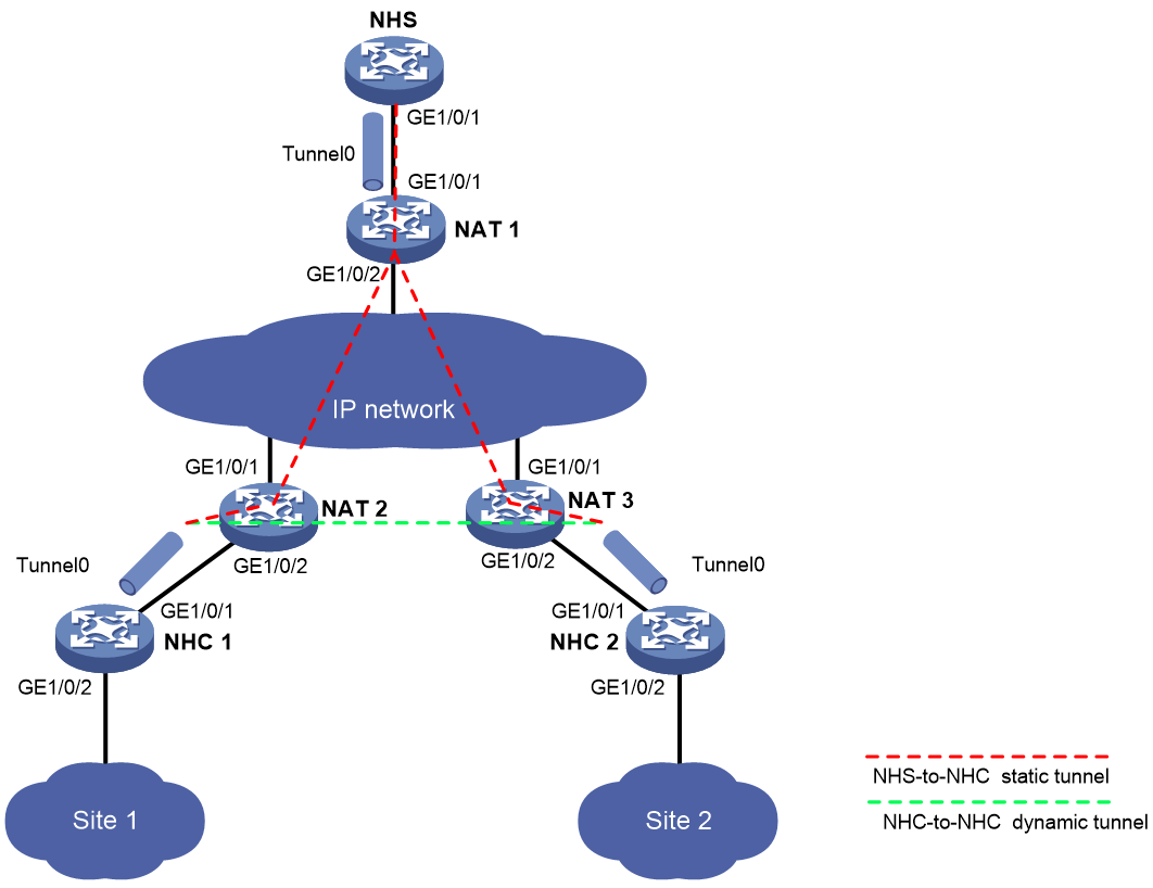
Table 1 Interface and IP address assignment
|
Device |
Interface |
IP address |
Device |
Interface |
IP address |
|
|
NHC 1 |
GE1/0/1 |
80.1.2.162/24 |
NAT 1 |
GE1/0/1 |
80.1.1.4/24 |
|
|
|
GE1/0/2 |
192.168.1.162/24 |
|
GE1/0/2 |
40.1.1.4/24 |
|
|
|
Tunnel0 |
192.168.4.162/24 |
NAT 2 |
GE1/0/1 |
40.1.1.2/24 |
|
|
NHC 2 |
GE1/0/1 |
80.1.3.163/24 |
|
GE1/0/2 |
80.1.2.2/24 |
|
|
|
GE1/0/2 |
192.168.0.163/24 |
NAT 3 |
GE1/0/1 |
40.1.1.3/24 |
|
|
|
Tunnel0 |
192.168.4.163/24 |
|
GE1/0/2 |
80.1.3.3/24 |
|
Procedure
|
|
CAUTION: The aging time for sessions in RAWIP-OPEN state set on NAT devices must be greater than the holdtime for NHRP mapping entries set on NHCs. For information about setting the aging time and holdtime, see the session aging-time state command and the nhrp holdtime command, respectively. |
1. Configure NHC 1:
# Configure an IP address for GigabitEthernet 1/0/1.
<NHC1> system-view
[NHC1] interface gigabitethernet 1/0/1
[NHC1-GigabitEthernet1/0/1] ip address 80.1.2.162 255.255.255.0
[NHC1-GigabitEthernet1/0/1] quit
# Configure an IP address for GigabitEthernet 1/0/2.
[NHC1] interface gigabitethernet 1/0/2
[NHC1-GigabitEthernet1/0/2] ip address 192.168.1.162 255.255.255.0
[NHC1-GigabitEthernet1/0/2] quit
# Configure an IP address for mGRE tunnel interface Tunnel0.
[NHC1] interface tunnel0 mode mgre
[NHC1-Tunnel0] ip address 192.168.4.162 255.255.255.0
# Specify GigabitEthernet 1/0/1 as the source interface of the mGRE tunnel.
[NHC1-Tunnel0] source gigabitethernet 1/0/1
# Set the GRE key to 100000.
[NHC1-Tunnel0] gre key 100000
# Set the NHRP network ID to 9.
[NHC1-Tunnel0] nhrp network-id 9
# Configure the NHRP packet authentication key as a plaintext string of 12345678.
[NHC1-Tunnel0] nhrp authentication simple 12345678
# Set the holdtime of NHRP mapping entries to 240 seconds.
[NHC1-Tunnel0] nhrp holdtime 240
# Configure an NHS private-to-public address mapping.
[NHC1-Tunnel0] nhrp nhs 192.168.4.161 nbma 40.1.1.9
[NHC1-Tunnel0] quit
# Configure static routes.
[NHC1] ip route-static 40.1.1.0 24 80.1.2.2
[NHC1] ip route-static 192.168.0.0 24 192.168.4.163
2. Configure NHC 2:
# Configure an IP address for GigabitEthernet 1/0/1.
<NHC2> system-view
[NHC2] interface gigabitethernet 1/0/1
[NHC2-GigabitEthernet1/0/1] ip address 80.1.3.163 255.255.255.0
[NHC2-GigabitEthernet1/0/1] quit
# Configure an IP address for GigabitEthernet 1/0/2.
[NHC2] interface gigabitethernet 1/0/2
[NHC2-GigabitEthernet1/0/2] ip address 192.168.0.163 255.255.255.0
[NHC2-GigabitEthernet1/0/2] quit
# Configure an IP address for mGRE tunnel interface Tunnel0.
[NHC2] interface tunnel0 mode mgre
[NHC2-Tunnel0] ip address 192.168.4.163 255.255.255.0
# Specify GigabitEthernet 1/0/1 as the source interface of the mGRE tunnel.
[NHC2-Tunnel0] source gigabitethernet 1/0/1
# Set the GRE key to 100000.
[NHC2-Tunnel0] gre key 100000
# Set the NHRP network ID to 9.
[NHC2-Tunnel0] nhrp network-id 9
# Configure the NHRP packet authentication key as a plaintext string of 12345678.
[NHC2-Tunnel0] nhrp authentication simple 12345678
# Set the holdtime of NHRP mapping entries to 240 seconds.
[NHC2-Tunnel0] nhrp holdtime 240
# Configure an NHS private-to-public address mapping.
[NHC2-Tunnel0] nhrp nhs 192.168.4.161 nbma 40.1.1.9
[NHC2-Tunnel0] quit
# Configure static routes.
[NHC2] ip route-static 40.1.1.0 24 80.1.3.3
[NHC2] ip route-static 192.168.1.0 24 192.168.4.162
3. Configure NAT 1:
# Configure an IP address for GigabitEthernet 1/0/1.
<NAT1> system-view
[NAT1] interface gigabitethernet 1/0/1
[NAT1-GigabitEthernet1/0/1] ip address 80.1.1.4 255.255.255.0
[NAT1-GigabitEthernet1/0/1] quit
# Configure an IP address for GigabitEthernet 1/0/2.
[NAT1] interface gigabitethernet 1/0/2
[NAT1-GigabitEthernet1/0/2] ip address 40.1.1.4 255.255.255.0
[NAT1-GigabitEthernet1/0/2] quit
# Enable static NAT on GigabitEthernet 1/0/2.
[NAT1] interface gigabitethernet 1/0/2
[NAT1-GigabitEthernet1/0/2] nat static enable
[NAT1-GigabitEthernet1/0/2] quit
# Configure an outbound static NAT mapping between interval IP address 80.1.1.161 and external IP address 40.1.1.9.
[NAT1] nat static outbound 80.1.1.161 40.1.1.9
4. Configure NAT 2:
# Configure an IP address for GigabitEthernet 1/0/1.
<NAT2> system-view
[NAT2] interface gigabitethernet 1/0/1
[NAT2-GigabitEthernet1/0/1] ip address 40.1.1.2 255.255.255.0
[NAT2-GigabitEthernet1/0/1] quit
# Configure an IP address for GigabitEthernet 1/0/2.
[NAT2] interface gigabitethernet 1/0/2
[NAT2-GigabitEthernet1/0/2] ip address 80.1.2.2 255.255.255.0
[NAT2-GigabitEthernet1/0/2] quit
# Create NAT address group 0, and add addresses 40.1.1.5 and 40.1.1.6 to the group.
[NAT2] nat address-group 0
[NAT2-nat-address-group-0] address 40.1.1.5 40.1.1.6
[NAT2-nat-address-group-0] quit
# Configure an outbound NO-PAT rule on interface GigabitEthernet 1/0/1 to translate the source addresses of outgoing packets into the addresses in address group 0. Enable reverse address translation.
[NAT2] interface gigabitethernet 1/0/1
[NAT2-GigabitEthernet1/0/1] nat outbound address-group 0 no-pat reversible
[NAT2-GigabitEthernet1/0/1] quit
5. Configure NAT 3:
# Configure an IP address for GigabitEthernet 1/0/1.
<NAT3> system-view
[NAT3] interface gigabitethernet 1/0/1
[NAT3-GigabitEthernet1/0/1] ip address 40.1.1.3 255.255.255.0
[NAT3-GigabitEthernet1/0/1] quit
# Configure an IP address for GigabitEthernet 1/0/2.
[NAT3] interface gigabitethernet 1/0/2
[NAT3-GigabitEthernet1/0/2] ip address 80.1.3.3 255.255.255.0
[NAT3-GigabitEthernet1/0/2] quit
# Create NAT address group 0, and add addresses 40.1.1.7 and 40.1.1.8 to the group.
[NAT3] nat address-group 0
[NAT3-nat-address-group-0] address 40.1.1.7 40.1.1.8
[NAT3-nat-address-group-0] quit
# Configure an outbound NO-PAT rule on interface GigabitEthernet 1/0/1 to translate the source addresses of outgoing packets into the addresses in address group 0. Enable reverse address translation.
[NAT3] interface gigabitethernet 1/0/1
[NAT3-GigabitEthernet1/0/1] nat outbound address-group 0 no-pat reversible
[NAT3-GigabitEthernet1/0/1] quit
Verifying the configuration
# Display detailed information about the NHRP mapping table on NHC 1.
[NHC1] display nhrp map verbose
Interface : Tunnel0
Destination/mask : 192.168.4.161/24
Next hop : 192.168.4.161
Creation time : 01:12:50
Expiration time : never expire
Type : static
Flags : up
NBMA address : 40.1.1.9
# Display brief information about the mGRE session on NHC 1.
[NHC1] display mgre session
Interface : Tunnel0
Number of sessions: 1
Peer NBMA address Peer protocol address Type State State duration
40.1.1.9 192.168.4.161 C-S Succeeded 01:12:43
The output indicates that NHC 1 has established a permanent tunnel with the NHS. The output on NHC 2 is similar.
# Ping the private address 192.168.4.163 of NHC 2 from NHC 1.
[NHC1] ping 192.168.4.163
Ping 192.168.4.163 (192.168.4.163): 56 data bytes, press CTRL_C to break
56 bytes from 192.168.4.163: icmp_seq=0 ttl=255 time=3.314 ms
56 bytes from 192.168.4.163: icmp_seq=1 ttl=255 time=2.786 ms
56 bytes from 192.168.4.163: icmp_seq=2 ttl=255 time=2.317 ms
56 bytes from 192.168.4.163: icmp_seq=3 ttl=255 time=3.060 ms
56 bytes from 192.168.4.163: icmp_seq=4 ttl=255 time=2.258 ms
--- Ping statistics for 192.168.4.163 ---
5 packets transmitted, 5 packets received, 0.0% packet loss
round-trip min/avg/max/std-dev = 2.258/2.747/3.314/0.411 ms
# Display detailed information about the NHRP mapping table on NHC 1.
[NHC1] display nhrp map verbose
Interface : Tunnel0
Destination/mask : 192.168.4.161/24
Next hop : 192.168.4.161
Creation time : 01:10:25
Expiration time : never expire
Type : static
Flags : up
NBMA address : 40.1.1.9
Interface : Tunnel0
Destination/mask : 192.168.4.163/32
Next hop : 192.168.4.163
Creation time : 00:00:24
Expiration time : 00:01:36
Type : cached
Flags : used up
NBMA address : 40.1.1.8
# Display brief information about the mGRE session on NHC 1.
[NHC1] display mgre session
Interface : Tunnel0
Number of sessions: 2
Peer NBMA address Peer protocol address Type State State duration
40.1.1.9 192.168.4.161 C-S Succeeded 00:10:28
40.1.1.8 192.168.4.163 C-C Succeeded 00:00:32
The output indicates that NHC 1 has established a permanent tunnel with the NHS and a temporary tunnel with NHC 2. The output on NHC 2 is similar.
