- Table of Contents
-
- 03-Security Configuration Guide
- 00-Preface
- 01-Security zone configuration
- 02-Security policy configuration
- 03-Object group configuration
- 04-Object policy configuration
- 05-AAA configuration
- 06-IPoE configuration
- 07-Portal configuration
- 08-User identification configuration
- 09-Password control configuration
- 10-Public key management
- 11-PKI configuration
- 12-SSH configuration
- 13-SSL configuration
- 14-ASPF configuration
- 15-APR configuration
- 16-Session management
- 17-Connection limit configuration
- 18-Attack detection and prevention configuration
- 19-DDoS protection configuration
- 20-uRPF configuration
- 21-ARP attack protection configuration
- 22-ND attack defense configuration
- 23-IP-MAC binding configuration
- 24-Keychain configuration
- 25-Crypto engine configuration
- 26-SMS configuration
- 27-Terminal identification configuration
- 28-Flow manager configuration
- 29-Location identification configuration
- 30-Server connection detection configuration
- 31-Trusted access control configuration
- Related Documents
-
| Title | Size | Download |
|---|---|---|
| 19-DDoS protection configuration | 487.43 KB |
Contents
DDoS attack traffic redirection
DDoS attack source verification
DDoS protection tasks at a glance
Setting the device deployment mode
Configuring DDoS protection parameters
Creating a non-default anti-DDoS zone
Enabling the default anti-DDoS zone
Configuring the global static blacklist
Configuring the global static whitelist
Configuring an anti-DDoS zone-based static blacklist
Configuring an anti-DDoS zone-based static whitelist
Configuring fingerprint protection
Setting the DDoS attack detection threshold
Enabling threshold learning for an anti-DDoS zone
Setting the aging time for dynamic blacklist entries
Setting the aging time for dynamic whitelist entries
Excluding interfaces from DDoS protection
Configuring DDoS protection log output
Display and maintenance commands for DDoS protection
DDoS protection configuration examples
Example: Configuring DDoS protection (inline deployment of cleaning device)
Example: Configuring DDoS protection (one-arm deployment of cleaning device)
Configuring DDoS protection
About DDoS protection
Hosts or servers on the Internet can initiate distributed denial of service (DDoS) attacks to temporarily or permanently paralyze the attack target. DDoS attacks are flooding attacks where packets from various sources consume network resources, cause network congestion, and increase the process workload. As a result, requests from legitimate users cannot be processed. DDoS attacks have higher volumes of attack traffic than traditional DoS attacks, and the DDoS attack sources are more difficult to be discovered.
The DDoS protection feature protects the network against DDoS attacks.
DDoS attack types
DDoS attackers exploit application layer protocols (such as DNS, HTTP, and SIP), transport layer protocols (TCP or UDP), and the IP protocol to launch DDoS attacks.
Application DDoS attacks
Attackers send a large number of forged application layer requests or replies to specific ports by taking advantage of application layer protocols. Busy processing these forged packets, the target system cannot respond to normal services.
DNS query flood attack
The DNS server processes and replies all incoming DNS queries.
A DNS flood attacker sends excessive forged DNS queries. This attack consumes the bandwidth and resources of the DNS server, and prevents the server from processing and replying legitimate DNS queries.
DNS reply flood attack
The DNS client processes all incoming DNS replies.
A DNS reply flood attacker sends excessive forged DNS replies. This attack consumes the bandwidth and resources of the DNS client, and prevents the client from processing legitimate DNS replies.
HTTP flood attack
Upon receiving an HTTP GET or POST request, the HTTP server performs complex operations, including character string searching, database traversal, data reassembly, and format switching. These operations consume a large amount of system resources.
An HTTP flood attacker sends a large number of HTTP GET or POST requests that exceed the processing capacity of the HTTP server, which causes the server to crash.
HTTPS flood attack
Upon receiving an HTTPS request, the HTTPS server performs complex operations, which consume a large amount of system resources.
An HTTPS flood attacker sends a large number of HTTPS requests that exceed the processing capacity of the HTTP server, which causes the server to crash.
SIP flood attack
After receiving a SIP INVITE packet from a SIP client, the server must allocate resources to establish and trace the session with the SIP client.
A SIP flood attacker sends a large number of fake INVITE request packets at a rate exceeding the processing capacity of the SIP server, which causes the server to crash.
HTTP slow attack
After an attacker establishes an HTTP connection with the HTTP server, it holds the connection for a long time to consume the server resources.
SSL renegotiation attack
After an attacker establishes an SSL connection with the HTTPS server, it keeps sending SSL renegotiation packets to the server to exhaust the server resources.
Connection-based DDoS attacks
The two ends of a TCP connection exchange SYN, ACK, SYN-ACK, and RST packets to establish or terminate the connection. Connection-based DDoS attacks use these packets to exhaust the connection resources and increase the processing burden of the target system.
SYN flood attack
When two ends are establishing a TCP connection, they consume memory resources to maintain their semi-connection information.
When an attacker sends a large number of SYN packets with forged source IP addresses, memory resources of the server will be exhausted. As a result, legitimate users cannot establish TCP connections to the server.
SYN-ACK flood attack
Upon receiving a SYN-ACK packet, the client must look for a matching TCP connection based on the packet quadruple (source IP address, source port number, destination IP address, and destination port number). This operation consumes computing resources of the client.
When an attacker sends a large number of forged SYN-ACK packets to the client, the client performance will be degraded and normal packets cannot be processed.
ACK flood attack
ACK packets are used in the TCP connection establishment, data transmission, and connection termination stages. When the server receives an ACK packet, it looks for a matching TCP connection based on the packet quadruple. This operation consumes computing resources of the server.
When an attacker sends a large number of forged ACK packets to the server, the workload of the server will be increased and the server cannot process normal packets.
RST flood attack
RST packets are used to abort TCP connections when TCP connection errors occur.
An RST flood attacker sends a large number of forged RST packets to a server. The victim might shut down correct connections, or be unable to provide services because it is busy searching for matching connections.
TCP fragment flood attack
The attacker sends a large number of forged TCP fragments to the server to severely consume server resources and network bandwidth. The server performance is degraded.
Volumetric DDoS attacks
Attacker sends massive packets of connectionless protocols to overwhelm network bandwidth of the target and prevent the target from processing normal packets.
UDP flood attack
An attacker sends a high volume of UDP packets to the server to saturate the server bandwidth. Normal packets destined for the server are delayed or even blocked. Typically, UDP flood attack packets are automatically generated by using the attack software and their source IP address, source port, and payload share common characteristics.
UDP fragment flood attack
An attacker sends a massive number of UDP fragments to occupy the server bandwidth and degrade the server performance. Normal requests to the server are delayed or even blocked.
ICMP flood attack
An attacker sends excessive ICMP packets to the server, which makes the server unable to process normal services. Network congestion also occurs because ICMP attack packets are usually of a big size.
ICMP fragment flood attack
An attacker sends a large volume of ICMP fragments to the server to cause network congestion and consume server resources in reassembling fragments.
IP traffic flood attack
An attacker sends a large number of IP packets to the server. The server cannot respond to normal requests because of the network link congestion.
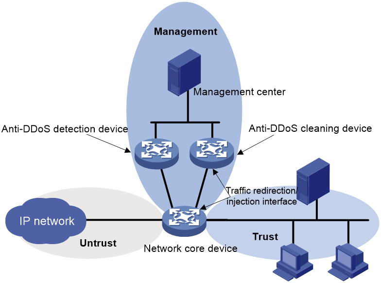
DDoS protection architecture
DDoS protection framework
A DDoS protection framework includes the following components:
· Anti-DDoS detection device—Detects DDoS attacks and reports attack information (including attack target IP address, target port number, and attack type) to the management center in attack alarm logs.
· Anti-DDoS cleaning device—Detects DDoS attacks, and scrubs DDoS attack traffic by dropping or rate limiting attack packets.
· Management center—Acts as the center of the framework and provides Web-based management interface. It provides the following features:
¡ Configures and manages the detection device and the cleaning device in a centralized way.
¡ Analyzes reports sent by the detection device and the cleaning device.
¡ Assigns the traffic redirection policy to the cleaning device deployed in the one-arm mode. For more information, see "Deployment modes."
¡ Displays anti-DDoS protection statistics.
For more information about configuring the management center, see the related online help.
In this document, the detection device and the cleaning device refer to the anti-DDoS detection device and anti-DDoS cleaning device, respectively.
Deployment modes
Inline deployment mode
As show in Figure 1, the cleaning device, located at the egress of the internal network, is deployed in the inline mode. The management center manages and monitors the cleaning device.
The inline deployment has the following characteristics:
· The network is simple. No detection device is deployed.
· The cleaning device directly cleans DDoS attack traffic without traffic redirect.
· The cleaning device might encounter a performance bottleneck when it processes both incoming and outgoing traffic.
This deployment mode is applicable to networks with small volumes of traffic, such as networks in small and medium-sized enterprises.
Figure 1 Inline deployment mode

In this mode, DDoS protection operates as follows:
1. The cleaning device monitors bidirectional traffic that passes through the device, and sends an attack alarm log to the management center when an attack is detected.
2. The management center analyzes the log, and assigns a defense instruction to the cleaning device to start the scrubbing process on the device. The instruction assignment can be manually confirmed.
3. The cleaning device drops or rate limits DDoS attack packets.
4. The cleaning device forwards the clean traffic.
One-arm deployment mode
As shown in Figure 2, both the detection device and the cleaning device are connected to the network core device and deployed in the one-arm mode. The management center manages and monitors the detection device and the cleaning device.
The one-arm mode has the following characteristics:
· The detection device monitors the traffic and detects DDoS attacks. The cleaning device scrubs attack traffic. The detection device and the cleaner work together to efficiently defend high volumes of DDoS attack traffics.
· Located at the egress of the network, the detection and cleaning device have a slight impact on other services. The network will not crash when a single point of failure occurs.
· The cleaning device scrubs only dynamically redirected attack traffic. For more information about the dynamic traffic redirection, see "DDoS attack traffic redirection."
The one-arm deployment mode is applicable to networks with high volumes of traffic, such as data centers.
Figure 2 One-arm deployment mode
In this mode, DDoS protection operates as follows:
1. The network core device uses the mirroring method to replicate incoming traffic to the detection device or sends flow statistics packets to the detection device. For more information, see "DDoS attack detection modes." The detection device examines the packets to determine whether a DDoS attack exists.
2. Upon detecting a DDoS attack, the detection device reports an attack alarm log to the management center.
3. The management center analyzes the log, informs the cleaning device to start the attack defense, and assigns a traffic redirection policy to it. The redirection policy contains a host route, which is also called the injection route. The destination IP address of the route is the attack target address, and the next hop is the IP address of the traffic-redirection/injection interface on the network core device.
4. Upon receiving the traffic redirection policy, the cleaning device sends the route to the core device through BGP. For more information about BGP, see Layer 3 IP Routing Configuration Guide.
5. The core device receives a host route with the destination IP address as the attack target address and the next hop as the IP address of the traffic-redirection/injection interface on the cleaning device. This route is called the traffic redirection route. The core device forwards traffic destined for the attack target address to the cleaning device.
6. The cleaning device drops or rate limits the attack traffic.
7. The cleaning device forwards the clean traffic to the core device through the injection route.
8. The core device forwards the clean traffic.
|
|
NOTE: To avoid the forwarding loop of the clean traffic, you must configure policy-based routing on the core device to redirect the clean traffic to the internal network. For more information about PBR, see Layer 3 IP Routing Configuration Guide. |
DDoS attack detection modes
The detection device supports the following DDoS attack detection modes:
· Deep packet inspection—DPI uses port mirroring to replicate all packets passing through the network core device to the detection device where they will be examined. This mode is applicable to scenarios that have small volumes of traffic and requires intensive DDoS attack detection, or scenarios that require detection at the application layer, such as enterprise networks.
· Deep flow inspection—DFI uses traffic collection technologies to sample packets passing through the network core device, encapsulates sampling results in the flow statistics packets, and then sends them to the detection device. Supported traffic collection protocols include NetFlow, NetStream, and sFlow. Traffic collection packets contains the following traffic summary information about the packets passing through the network core device: destination IP address, source IP address, destination port number, source port number, protocol, ToS, and packet length. The application layer information is not contained. This mode is applicable to scenarios that have high volumes of traffic and require extensive DDoS attack detection, such as MAN networks.
Cleaning devices deployed in the inline mode supports only the DPI mode.
DDoS attack traffic redirection
Cleaning devices support the following types of traffic redirection methods:
· Static traffic redirection—Traffic redirection policies configured on the management center are manually assigned to the cleaning device. Each policy redirects packets with the specified destination IP address to the cleaning device for DDoS attack detection and cleaning.
In this mode, all packets matching the policy are redirected to the cleaning device, no matter whether they are attack packets or not. Use this method if the protected targets require real-time DDoS protection.
· Dynamic traffic redirection—When the detection device detects a DDoS attack, it reports a log to the management center where a traffic redirection policy is generated. The policy can be automatically assigned to the cleaning device with or without user confirmation.
In this mode, only DDoS attack traffic that matches the policy is redirected to the cleaning device for scrubbing. The destination IP address of the matching traffic is the IP address of the attack target. This method improves packet processing efficiency.
A cleaning device can use both static and dynamic traffic redirection methods to meet different DDoS protection demands.
DDoS protection mechanism
DDoS protection workflow
DDoS protection detects and cleans DDoS attack traffic in the following workflow:
1. DDoS attack detection—The detection device analyzes mirrored packets and flow statistics packets, and reports a log to the management center once an attack is detected.
2. DDoS attack traffic cleaning—The cleaning device scrubs the attack traffic by using the following features step by step:
a. Blacklist—Drops packets from specific subnets.
b. Whitelist—Permits packets from specific subnets to pass through.
c. Filters—Take an action on packets matching a filter.
d. Fingerprint protection—Matches the redirected traffic based on fingerprint signatures, and drops and rate limits the matching packets.
e. Second DDoS attack detection—Identifies real DDoS attack packets because statically redirected traffic might contain irrelevant traffic.
f. Source verification—Acts as a proxy server to verify packet sources.
g. Rate limiting—Limits the packet rate based on the threshold settings.
Anti-DDoS zone
An anti-DDoS zone is a set of protected IP addresses. To simplify DDoS protection configuration, you can add IP addresses that require the same DDoS protection to one zone.
The following types of anti-DDoS zones are available:
· Default anti-DDoS zone—Always exists and protects all IP addresses by default. You do not need to assign IP addresses to the zone.
· Non-default anti-DDoS zones—Require manual creation. IP addresses in these zones are manually added.
To process a packet for DDoS protection, the device first determines whether the destination IP address of the packet is in a non-default anti-DDoS zone.
· If the destination IP address is in a non-default zone, the device processes the packet based on the DDoS protection configuration in the zone.
· If the destination IP address is not in any non-default zone, the device processes the packet as follows:
¡ If the default anti-DDoS zone is enabled, the device processes the packet based on the DDoS protection configuration of the default zone.
¡ If the default anti-DDoS zone is disabled, the device sends the packet to the subsequent process without DDoS protection processing.
DDoS attack detection
The traffic of a specific protocol is DDoS attack traffic if the traffic threshold is violated. When you set the detection threshold for traffic of a protocol in a zone, the DDoS attack detection is enabled for packets of this protocol in this zone. The device counts the number of the protocol packets per second sent to each IP address in the zone. If the number of the packets destined for an IP address exceeds the detection threshold, the IP address is being attacked.
If the types and volumes of traffic passing through the device change frequently, user-defined detection thresholds cannot meet the actual anti-DDoS needs.
· A higher threshold might mistakenly permit the DDoS attack traffic to pass though, bringing severe security risk to the network.
· A lower threshold might mistakenly drop legitimate traffic, blocking normal network access.
To obtain a reasonable threshold in the live network, enable automatic threshold learning in the zone. This feature allows the device to periodically collect statistics of protocol packets destined for IP addresses in the zone, and report statistics to the management center. The management center analyzes the statistics, calculates the detection threshold, and deploys the defense policy.
Filters
Filters allow you to configure general match rules and protocol-specific rules to implement packet filtering in a finer granularity. General packet match rules can be based on the protocol number, port number, and IP address.
Fingerprint protection
Fingerprint signatures include the packet length, TTL, source port number, destination port number, and payload information. The fingerprint protection uses fingerprint signatures for packet match, and filters out or rate limits the matching packets. It can effectively defend against volumetric DDoS attacks, such as UDP flood attack.
Fingerprint signatures on a cleaning device can be manually configured or automatically learned.
· To manually configure fingerprint signatures, specify the fingerprint content, the fingerprint offset in the IP header, and fingerprint length. The device counts the number of packets that have the matching fingerprint signature in the IP header. A fingerprint signature is hit if the fingerprint content obtained based on the offset value and fingerprint length is the same as the defined fingerprint content. When the number of matching packets exceeds the fingerprint protection threshold, the device takes an action on the subsequent matching packets.
· To enable the cleaning device to automatically learn fingerprint signatures from attack packets, specify the fingerprint offset in the IP header and the fingerprint length. The cleaning device collects the packet signature based on the fingerprint offset value and fingerprint length. A packet signature becomes a fingerprint signature if the packet signature has a high occurrence. When the number of packets with the matching signature exceeds the threshold, the device takes an action on the subsequent matching packets.
DDoS attack source verification
This feature prevents application flood attacks and SYN flood attack. After you enable this feature for a protocol on the cleaning device, the device will act as a proxy to protect application layer or TCP connections.
When the cleaning device detects an application attack or SYN flood attack aimed to a server, the device adds the server IP address as a protected IP address for source verification, and verifies the source. Packets that fail the source verification are dropped.
SYN source verification
This feature supports only the safe reset mode. This mode is also known as the unidirectional TCP proxy mode because the device processes only external SYN packets destined for the internal network.
As shown in Figure 3, the safe reset mode functions as follows:
1. After receiving a SYN packet destined for a protected server, the TCP proxy sends back a SYN ACK packet with an invalid sequence number.
2. If the TCP proxy receives an RST packet from the client, the client is verified as legitimate.
3. The TCP proxy adds the client's IP address to the trusted IP list. The client initiates the connection again and the TCP proxy directly forwards the TCP packets to the server.
The safe reset mode requires that TCP clients comply with the TCP protocol suite. The TCP proxy will deny a legitimate client to access the server if the client does not comply with the TCP protocol suite.
With source verification, the TCP connection establishment takes more time than normal TCP connection establishment.
Figure 3 TCP proxy in safe reset mode

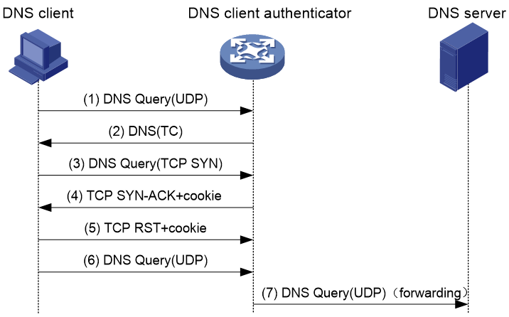
DNS query source verification
The device with DNS query source verification feature configured is called a DNS client authenticator.
As shown in Figure 4, the DNS source verification functions as follows:
1. Upon receiving a UDP DNS query destined for a protected server, the DNS client authenticator responds with a DNS truncate (TC) packet. The DNS truncate packet requires the client to initiate a query in a TCP packet.
2. When the authenticator receives a DNS query in a TCP SYN packet to port 53 from the client, the authenticator responds with a SYN-ACK packet that contains an incorrect sequence number.
3. When the authenticator receives a RST packet from the client, the authenticator verifies the client as legitimate.
4. The authenticator adds the client's IP address to the trusted IP list and forwards the trusted client's subsequent packets to the server.
Figure 4 DNS source verification process
The DNS source verification feature requires that clients use the standard TCP/IP protocol suite and DNS protocol. Legitimate clients that use non-standard protocols will be verified as illegitimate by the DNS client authenticator.
With source verification, the first DNS resolution takes more time than normal DNS resolution.
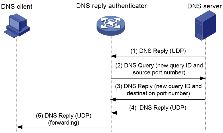
DNS reply source verification
The device with DNS reply source verification feature configured is called a DNS reply authenticator.
As shown in Figure 5, the DNS reply verification functions as follows:
1. Upon receiving a UDP DNS reply destined for a protected client, the DNS reply authenticator sends back a DNS query packet with the locally generated query ID and port number.
2. After receiving the DNS query, a valid DNS server responds with a DNS reply that contains a new query ID and destination port.
3. The DNS reply authenticator verifies the query ID and destination port in the reply. If the query ID and destination port are the same as the query ID and port number the authenticator has sent, the DNS server passes verification. The authenticator will forward subsequent packets from the server.
Figure 5 DNS reply verification process
HTTP GET source verification
The device with HTTP source verification feature configured is called an HTTP client authenticator.
When an HTTP client authenticator receives a SYN packet from a client, the authenticator first performs TCP source verification in SYN Cookie mode as a TCP proxy, as shown in Figure 6:
1. After receiving a SYN packet from a client to a protected server, the TCP proxy sends back a SYN ACK packet with the window size 0. If the client responds with an ACK packet, the client is verified as legitimate. The proxy device establishes a TCP connection with the client.
2. The TCP proxy device establishes a connection with the server through a new three-way handshake that has a different window size. This connection uses a different sequence number from the connection between the client and proxy device.
Figure 6 TCP proxy in SYN cookie mode

After the client passes TCP source verification, the HTTP client authenticator uses HTTP GET requests to verify the HTTP client as follows, as shown in Figure 7:
3. When the authenticator receives an HTTP GET packet from the client, it performs the first redirect verification. The authenticator records the client information and responds with an HTTP Redirect packet. The HTTP Redirect packet contains a redirect URI and requires the client to terminate the TCP connection.
4. After receiving the HTTP Redirect packet, the client terminates the TCP connection and then establishes a new TCP connection with the authenticator.
5. When the authenticator receives the HTTP GET packet, it performs the second redirection verification. The authenticator verifies the following information:
¡ The client has passed the first redirection verification.
¡ The URI in the HTTP GET packet is the redirect URI.
6. If the client passes the second redirection verification, the authenticator adds its IP address to the trusted IP list, and responds a Redirect packet. The Redirect packet contains the URI that the client originally carried and requires the client to terminate the TCP connection.
7. The authenticator directly forwards the trusted client's subsequent packets to the server.
Figure 7 HTTP GET source verification process

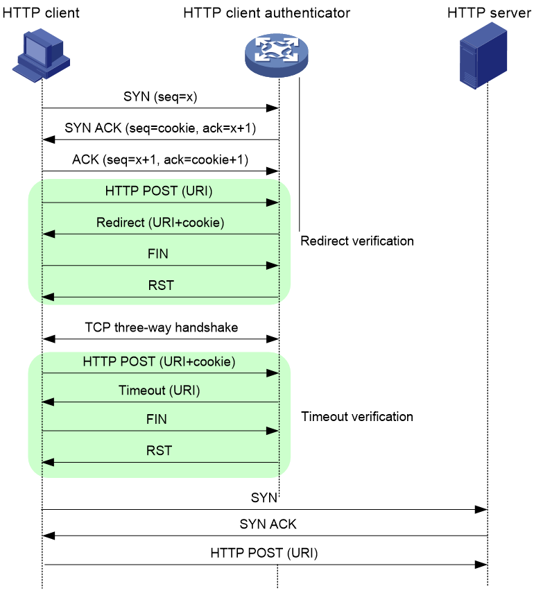
HTTP POST source verification
As shown in Figure 8, the HTTP client authenticator uses HTTP POST requests to verify the HTTP client as follows:
1. Upon receiving a SYN packet destined for a protected HTTP server, the HTTP client authenticator performs TCP source verification in SYN Cookie mode. If the client passes the TCP source verification, a TCP connection is established between the client and the authenticator.
2. When the authenticator receives an HTTP POST request from the client, it performs the redirect verification. The authenticator records the client information and responds with an HTTP Redirect packet. The HTTP Redirect packet contains a redirect URI and the Set-Cookie header, and requires the client to terminate the TCP connection.
3. After receiving the HTTP Redirect packet, the client terminates the TCP connection and then establishes a new TCP connection with the authenticator.
4. When the authenticator receives the HTTP POST request, it performs the timeout verification. The authenticator verifies the following information:
¡ The client has passed the redirection verification.
¡ The HTTP POST request contains a valid cookie.
5. If the client passes the timeout verification, the authenticator adds its IP address to the trusted IP list, and responds with an HTTP Timeout packet. The Timeout packet contains the URI that the client originally carried and requires the client to terminate the TCP connection.
6. The authenticator directly forwards the trusted client's subsequent packets to the server.
Figure 8 POST source verification process
SIP source verification
A device with the SIP source verification feature configured is called an SIP client authenticator.
As shown in Figure 9, the SIP source verification functions as follows:
1. Upon receiving a UDP INVITE packet destined for a protected server, the SIP client authenticator sends back an OPTIONS packet with a branch value.
2. After receiving the OPTIONS packet, the client sends an OPTIONS ACK to the SIP client authenticator.
3. When receiving the OPTIONS ACK, the SIP client authenticator verifies the branch value in the OPTIONS ACK.
¡ If the branch value in the OPTIONS ACK is the same as the branch value in the OPTIONS packet that the SIP client authenticator has sent, the client passes verification. The authenticator will forward subsequent packets from the client.
¡ If the branch value in the OPTIONS ACK is different from the branch value in the OPTIONS packet that the SIP client authenticator has sent, the client fails verification. The authenticator drops packets from the client.
Figure 9 SIP source verification process

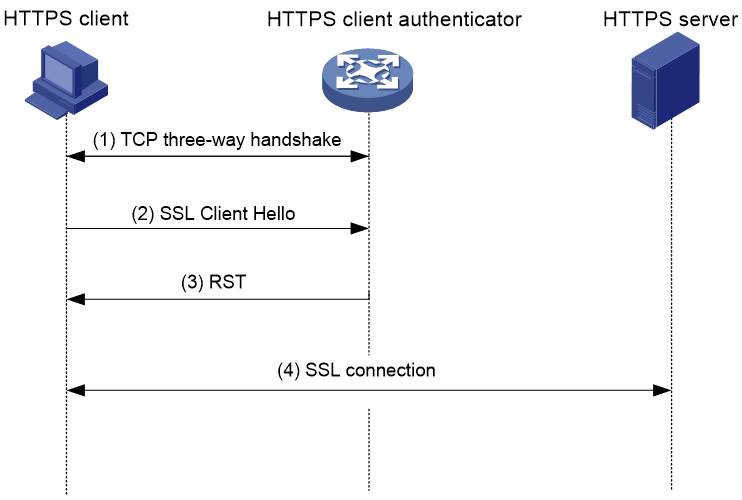
HTTPS source verification
As shown in Figure 10, the HTTPS source verification functions as follows:
1. After the HTTPS client and the HTTPS client authenticator establish a TCP connection, the client sends a client hello message to the authenticator.
¡ If the authenticator receives this hello message, it verifies the client as legitimate and adds the client address to the trusted IP list. The authenticator will forward subsequent packets from this client.
¡ If the authenticator does not receive the client hello message, the authenticator verifies the client as illegitimate, and it will drop subsequent packets from the client.
2. The authenticator sends an RST packet to the legitimate client to terminate the TCP connection. The client then can establish an SSL connection with the HTTPS server.
Figure 10 HTTPS source verification process
Blacklist
A cleaning device supports the following types of blacklists:
· Global static blacklist—The entries are manually configured. They never expire unless they are manually deleted from the blacklist. The device drops packets whose source IP addresses match the global static blacklist entries.
· Anti-DDoS zone-based static blacklist—The entries are manually configured. They never expire unless they are manually deleted from the blacklist. The device drops packets destined for an anti-DDoS zone if their source IP addresses match the static blacklist entries of this zone.
· Dynamic blacklist—The device automatically adds IP addresses that fail source verification to the dynamic blacklist. The device drops packets whose source IP addresses are on the dynamic blacklist.
Whitelist
A cleaning device supports the following types of whitelists:
· Global static whitelist—The entries are manually configured. They never expire unless they are manually deleted from the whitelist. Packets whose source IP addresses match the global static whitelist entries are permitted to pass through. The device takes only the rate limiting action on these packets if their rate exceeds the threshold.
· Anti-DDoS zone-based static whitelist—The entries are manually configured. They never expire unless they are manually deleted from the whitelist. Packets destined for an anti-DDoS zone are permitted to pass through if their source IP addresses match the static whitelist entries of this zone. The device takes only the rate limiting action on these packets if their rate exceeds the threshold.
· Trusted IP list—The device automatically adds IP addresses that pass source verification to the trusted IP list. Packets with the source IP address on the trusted IP list are allowed to pass through. The device takes only the rate limiting action on these packets if the packet rate exceeds the threshold.
Packet rate limiting
When packets of a specified type destined for an IP address in an anti-DDoS zone exceeds the rate threshold, the cleaning device drops packets that exceed the threshold.
DDoS protection logs
The management center collects traffic types and volumes and traces DDoS attacks based on different types of DDoS protection logs.
Traffic analysis logs
A traffic analysis log contains the packet rate and protocol type.
The cleaning device deployed in the inline mode and the detection device regularly send traffic analysis logs to the management center during their running period.
The cleaning device deployed in the one-arm mode starts regularly sending traffic analysis logs to the management center after receiving the protection instruction from the management center. It stops reporting traffic analysis logs after receiving the protection end instruction.
Attack alarm logs
A DDoS attack alarm log contains the attack target IP address, port number, and attack traffic information. The cleaning device deployed in the inline mode or the detection device can report attack start and end events to the management center in attack alarm logs.
· When a DDoS detection threshold is violated, the device detects a DDoS attack and sends an attack start log to the management center.
· When the attack packet rate drops below the silence threshold (three-fourths of the threshold), the DDoS attack ends and the device sends an attack end log to the management center.
The similar mechanism applies when the fingerprint protection reports DDoS attack logs to the management center.
Attack information logs
When a DDoS attack occurs, the detection device regularly reports attack information logs to the management center. An attack information log contains the following information: destination IP address, destination port number, source IP address, source port, and attack traffic information. The detection device stops reporting attack information logs when it detects that the DDoS attack ends.
Cleaning devices do not support reporting attack log information.
Logs of top 5 fingerprints
Logs of this type record top 5 fingerprint hit statistics in each fingerprint policy group. Cleaning devices report top 5 fingerprint logs at intervals of 1 minute.
Restrictions and guidelines
The DDoS protection and attack detection and prevention features are mutually exclusive. Do not configure both features on the device. For more information about attack detection and prevention, see "Configuring attack detection and prevention."
DDoS protection tasks at a glance
To configure DDoS protection on a cleaning device, perform the following tasks:
1. Setting the device deployment mode
2. Configuring DDoS protection parameters
a. Creating a non-default anti-DDoS zone
b. (Optional.) Enabling the default anti-DDoS zone
c. (Optional.) Configuring the global static blacklist
d. (Optional.) Configuring the global static whitelist
e. (Optional.) Configuring an anti-DDoS zone-based static blacklist
f. (Optional.) Configuring an anti-DDoS zone-based static whitelist
g. (Optional.) Configuring filters
h. (Optional.) Configuring fingerprint protection
i. (Optional.) Customizing DDoS attack types
j. Setting the DDoS attack detection threshold
This feature identifies DDoS packets in statically redirected traffic.
k. (Optional.) Enabling threshold learning for an anti-DDoS zone
l. (Optional.) Enabling source verification
m. (Optional.) Setting the aging time for dynamic blacklist entries
n. (Optional.) Setting the aging time for dynamic whitelist entries
3. Excluding interfaces from DDoS protection
4. Configuring DDoS protection log output
Setting the device deployment mode
About this task
Use this feature to configure the device deployment mode in the DDoS protection framework.
The inline and one-arm deployment modes are supported.
Restrictions and guidelines
This feature is available only on cleaning devices.
Detection devices support only the one-arm deployment mode.
Procedure
1. Enter system view.
system-view
2. Set the deployment mode for the cleaning device.
anti-ddos cleaner deploy-mode { inline | out-of-path }
By default, the cleaning device uses the inline deployment mode.
Configuring DDoS protection parameters
Creating a non-default anti-DDoS zone
About this task
DDoS protection implements hierarchical protection on a per anti-DDoS zone basis. The DDoS protection configuration in an anti-DDoS zone apply to all IP addresses in this zone.
Procedure
1. Enter system view.
system-view
2. Create a non-default anti-DDoS zone and enter its view.
anti-ddos zone id zone-id
3. (Optional.) Specify a name for the zone.
name zone-name
By default, no name is specified for the non-default zone.
4. Add an IPv4 address range.
ip-range start-ip end-ip
By default, no IPv4 address ranges exist in the non-default zone.
5. Add an IPv6 address range.
ipv6-range start-ip end-ip
By default, no IPv6 address ranges exist in the non-default zone.
Enabling the default anti-DDoS zone
About this task
The default anti-DDoS zone is used for configuring the default DDoS protection parameters. If the IP addresses of packets passing through the device do not belong to any non-default anti-DDoS zone, the DDoS protection in the default anti-DDoS zone applies.
Procedure
1. Enter system view.
system-view
2. Enable the default anti-DDoS zone.
anti-ddos default-zone enable
By default, the default anti-DDoS zone is disabled.
Configuring the global static blacklist
About this task
The global static blacklist drops packets from a subnet that is defined by the IP address and mask length.
Procedure
1. Enter system view.
system-view
2. Add a global static blacklist entry.
anti-ddos blacklist { ip source-ip-address ip-mask-length | ipv6 source-ipv6-address ipv6-mask-length }
By default, no global static blacklist entries exist.
Configuring the global static whitelist
About this task
The global static whitelist permits packets from a subnet that is defined by the IP address and mask length.
Procedure
1. Enter system view.
system-view
2. Add a global static whitelist entry.
anti-ddos whitelist { ip source-ip-address ip-mask-length | ipv6 source-ipv6-address ipv6-mask-length }
By default, no global static whitelist entries exist.
Configuring an anti-DDoS zone-based static blacklist
About this task
The device drops packets that are destined for an anti-DDoS zone if their source IP addresses match static blacklist entries for this zone. To configure an anti-DDoS zone-based static blacklist entry for a subnet, specify an IP address and mask length.
Procedure
1. Enter system view.
system-view
2. Enter anti-DDoS zone view.
anti-ddos zone { id zone-id | default }
3. Configure an anti-DDoS zone-based static blacklist entry.
zone-blacklist { ip source-ip-address ip-mask-length | ipv6 source-ipv6-address ipv6-mask-length }
By default, no anti-DDoS zone-based static blacklist entries exist.
Configuring an anti-DDoS zone-based static whitelist
About this task
The device permits packets that are destined for an anti-DDoS zone to pass through if their source IP addresses match static whitelist entries for this zone. To configure an anti-DDoS zone-based static whitelist entry for a subnet, specify an IP address and mask length.
Procedure
1. Enter system view.
system-view
2. Enter anti-DDoS zone view.
anti-ddos zone { id zone-id | default }
3. Configure an anti-DDoS zone-based static whitelist entry.
zone-whitelist { ip source-ip-address ip-mask-length | ipv6 source-ipv6-address ipv6-mask-length }
By default, no anti-DDoS zone-based static whitelist entries exist.
Configuring filters
About this task
A filter contains a set of rules for identifying packets based on specified criteria. The device uses the rules to identify packets and takes a user-defined action (dropping packets, rate limiting, allowing packets to pass, or source verification) on the matching packets.
You can configure both general rules and protocol-specific rules in a filter.
· General rules—Include packet fingerprint rules and rules to match the source IP address, destination IP address, DSCP, TTL, fragment status, and packet length fields. These rules can be configured in all types of filters.
· Protocol-specific rules—Vary by the filter type as follows:
¡ IP filter—Matches the protocol field.
¡ TCP filter—Matches the TCP flags, source port number, and destination port number fields.
¡ UDP filter—Matches the source port number and destination port number fields.
¡ DNS filter—Matches the packet type, QR field, domain name field, and source port number fields.
¡ HTTP filter—Matches the cookie, host, referer, user-agent, TCP flags, request packet type, and request URI fields. HTTP filters support using source verification as a defensive action.
¡ SIP filter—Matches the callee, caller, and source port number fields.
Restrictions and guidelines
This feature is available only on the cleaning devices.
In one filter, you can configure multiple match rules for the same field.
Configuring general rules
1. Enter system view.
system-view
2. Enter filter view.
anti-ddos filter name filter-name [ type { dns | http | icmp | ip | sip | tcp | udp } ]
3. Configure a source IP address match rule.
source-ip { ip-range start-ip end-ip | ipv6-range start-ipv6 end-ipv6 }
By default, no source IP address match rules are configured.
4. Configure a destination IP address match rule.
destination-ip { ip-range start-ip end-ip | ipv6-range start-ipv6 end-ipv6 }
By default, no destination IP address match rules are configured.
5. Configure a packet fingerprint match rule.
fingerprint id { offset offset-value content content [ depth depth-value ] } &<1-4>
By default, no packet fingerprint match rules are configured.
6. Configure a DSCP match rule.
dscp dscp
By default, no DSCP match rules are configured.
7. Configure a fragment match rule.
fragment { donot | first | last | middle | non }
By default, no fragment match rules are configured.
8. Configure a TTL match rule.
ttl ttl-value
By default, no TTL match rules are configured.
9. Configure a packet length match rule.
packet-length range length1 length2
By default, no packet length match rules are configured.
10. Specify an action on the packets that match the filter.
action { drop | limit { bit-based value | packet-based value } | pass }
By default, the device drops the packets that match the filter.
11. Enter anti-DDoS zone view.
anti-ddos zone { id zone-id | default }
12. Apply the filter to the zone.
anti-ddos apply filter filter-name preference preference
By default, no filters are applied to an anti-DDoS zone.
Configuring an IP filter
1. Enter system view.
system-view
2. Enter IP filter view.
anti-ddos filter name filter-name type ip
3. Configure a protocol field match rule.
protocol protocol-number
By default, no protocol field match rules are configured.
4. Specify an action on the packets that match the filter.
action { drop | limit { bit-based value | packet-based value } | pass }
By default, the device drops the packets that match the filter.
5. Enter anti-DDoS zone view.
anti-ddos zone { id zone-id | default }
6. Apply the filter to the zone.
anti-ddos apply filter filter-name preference preference
By default, no filters are applied to an anti-DDoS zone.
Configuring a TCP filter
1. Enter system view.
system-view
2. Enter TCP filter view.
anti-ddos filter name filter-name type tcp
3. Configure a source port match rule.
source-port range port1 port2
By default, no source port match rules are configured.
4. Configure a destination port match rule.
destination-port range port1 port2
By default, no destination port match rules are configured.
5. Configure a TCP flags field match rule.
tcp-flag tcp-flag
By default, no TCP flags field match rules are configured.
6. Specify an action on the packets that match the filter.
action { drop | limit { bit-based value | packet-based value } | pass }
By default, the device drops the packets that match the filter.
7. Enter anti-DDoS zone view.
anti-ddos zone { id zone-id | default }
8. Apply the filter to the zone.
anti-ddos apply filter filter-name preference preference
By default, no filters are applied to an anti-DDoS zone.
Configuring a UDP filter
1. Enter system view.
system-view
2. Enter UDP filter view.
anti-ddos filter name filter-name type udp
3. Configure a source port match rule.
source-port range port1 port2
By default, no source port match rules are configured.
4. Configure a destination port match rule.
destination-port range port1 port2
By default, no destination port match rules are configured.
5. Specify an action on the packets that match the filter.
action { drop | limit { bit-based value | packet-based value } | pass }
By default, the device drops the packets that match the filter.
6. Enter anti-DDoS zone view.
anti-ddos zone { id zone-id | default }
7. Apply the filter to the zone.
anti-ddos apply filter filter-name preference preference
By default, no filters are applied to an anti-DDoS zone.
Configuring a DNS filter
1. Enter system view.
system-view
2. Enter DNS filter view.
anti-ddos filter name filter-name type dns
3. Configure a source port match rule.
source-port range port1 port2
By default, no source port match rules are configured.
4. Configure a domain name field match rule.
domain { equal | include } domain-string
By default, no domain name field match rules are configured.
5. Configure a QR field match rule.
qr { query | reply }
By default, no QR field match rules are configured.
6. Configure a DNS type match rule.
type type
By default, no DNS type match rules are configured.
7. Specify an action on the packets that match the filter.
action { drop | limit { bit-based value | packet-based value } | pass }
By default, the device drops the packets that match the filter.
8. Enter anti-DDoS zone view.
anti-ddos zone { id zone-id | default }
9. Apply the filter to the zone.
anti-ddos apply filter filter-name preference preference
By default, no filters are applied to an anti-DDoS zone.
Configuring an HTTP filter
1. Enter system view.
system-view
2. Enter HTTP filter view.
anti-ddos filter name filter-name type http
3. Configure a user-agent field match rule for HTTP packets.
user-agent include user-agent
By default, no user-agent field match rules are configured for HTTP packets.
4. Configure a URI match rule for HTTP packets.
request-uri include uri
By default, no URI match rules are configured for HTTP packets.
5. Configure a referer field match rule for HTTP packets.
referer include referer-string
By default, no referer field match rules are configured for HTTP packets.
6. Configure a request packet type match rule for HTTP packets.
opcode { connect | delete | get | head | options | post | put | trace }
By default, no request packet type match rules are configured for HTTP packets.
7. Configure a host field match rule.
host include host
By default, no host field match rules are configured for HTTP packets.
8. Configure a cookie field match rule for HTTP packets.
cookie include cookie
By default, no cookie field match rules are configured for HTTP packets.
9. Specify an action on the packets that match the filter.
action { drop | limit { bit-based value | packet-based value } | pass | source-verify }
By default, the device drops the packets that match the filter.
10. Enter anti-DDoS zone view.
anti-ddos zone { id zone-id | default }
11. Apply the filter to the zone.
anti-ddos apply filter filter-name preference preference
By default, no filters are applied to an anti-DDoS zone.
Configuring a SIP filter
1. Enter system view.
system-view
2. Enter SIP filter view.
anti-ddos filter name filter-name type sip
3. Configure a source port match rule.
source-port range port1 port2
By default, no source port match rules are configured.
4. Configure a callee field match rule for SIP packets.
callee { equal | include } callee-string
By default, no callee field match rules are configured for SIP packets.
5. Configure a caller field match rule for SIP packets.
caller { equal | include } caller-string
By default, no caller field match rules are configured for SIP packets.
6. Specify an action on the packets that match the filter.
action { drop | limit { bit-based value | packet-based value } | pass }
By default, the device drops the packets that match the filter.
7. Enter anti-DDoS zone view.
anti-ddos zone { id zone-id | default }
8. Apply the filter to the zone.
anti-ddos apply filter filter-name preference preference
By default, no filters are applied to an anti-DDoS zone.
Configuring fingerprint protection
About this task
A fingerprint policy contains fingerprint signatures for packet match and a defensive action (drop, permit, or rate limiting) on the matching packets. Fingerprint signatures can be manually configured or automatically learned.
For a fingerprint policy to take effect in an anti-DDoS zone, configure the policy in a fingerprint protection group, and apply the group to the zone.
Restrictions and guidelines
This feature is available only on cleaning devices.
Procedure
1. Enter system view.
system-view
2. Enter the view of a fingerprint policy group.
fingerprint-group { ip | ipv6 } group-id
3. Configure a fingerprint policy.
fingerprint id protocol { icmp | other | tcp | udp } { offset offset-value length length-value [ content content ] } &<1-3> threshold threshold-value action { bandwidth-limit | drop | watch }
By default, no fingerprint policies exist in the fingerprint policy group.
4. Enter anti-DDoS zone view.
anti-ddos zone { id zone-id | default }
5. Apply the fingerprint policy group to the anti-DDoS zone.
fingerprint-group apply { ip | ipv6 } group-id
By default, no fingerprint policy group is applied to the anti-DDoS zone.
Setting the DDoS attack detection threshold
About this task
The DDoS attack detection threshold is critical to DDoS protection. When the receiving rate of packets of a specific protocol destined for an IP address reaches or exceeds the threshold, a DDoS attack occurs. When the receiving rate of the packets is below the silence threshold (three-fourths of the detection threshold) within 5 seconds, the DDoS attack ends.
If you configure DDoS attack detection thresholds for multiple types of protocol packets, the device detects attacks in the following descending order:
1. Application attacks, including DNS query, DNS reply, HTTP, and SIP attacks.
2. Connection-based attacks and volumetric attacks, including SYN, SYN-ACK, ACK, RST, UDP, and ICMP attacks.
Once the device detects a DDoS attack on an IP address, the detection process stops and the device performs the following operation:
· The detection device sends an attack log to the management center and detects DDoS attacks on subsequent packets.
· The cleaning device cleans the DDoS attack packets.
Setting a threshold for DNS query flood attack protection
1. Enter system view.
system-view
2. Enter anti-DDoS zone view.
anti-ddos zone { id zone-id | default }
3. Enable DNS query flood attack detection and set a detection threshold.
dns-query-flood detection threshold { bit-based value | packet-based value }
By default, DNS query flood attack detection is disabled and no threshold is set.
Setting a threshold for DNS reply flood attack protection
1. Enter system view.
system-view
2. Enter anti-DDoS zone view.
anti-ddos zone { id zone-id | default }
3. Enable DNS reply flood attack detection and set a detection threshold.
dns-reply-flood detection threshold { bit-based value | packet-based value }
By default, DNS reply flood attack detection is disabled and no threshold is set.
Setting a threshold for HTTP flood attack protection
1. Enter system view.
system-view
2. Enter anti-DDoS zone view.
anti-ddos zone { id zone-id | default }
Enable HTTP flood attack detection and set a detection threshold.
http-flood detection threshold { bit-based value | packet-based value }
By default, HTTP flood attack detection is disabled and no threshold is set.
Setting a threshold for SIP flood attack protection
1. Enter system view.
system-view
2. Enter anti-DDoS zone view.
anti-ddos zone { id zone-id | default }
3. Enable SIP flood attack detection and set a detection threshold.
sip-flood detection threshold { bit-based value | packet-based value }
By default, SIP flood attack detection is disabled and no threshold is set.
Setting a threshold for SYN flood attack protection
1. Enter system view.
system-view
2. Enter anti-DDoS zone view.
anti-ddos zone { id zone-id | default }
3. Enable SYN reply flood attack detection and set a detection threshold.
syn-flood detection threshold { bit-based value | packet-based value }
By default, SYN flood attack detection is disabled and no threshold is set.
Setting a threshold for SYN-ACK flood attack protection
1. Enter system view.
system-view
2. Enter anti-DDoS zone view.
anti-ddos zone { id zone-id | default }
3. Enable SYN-ACK flood attack detection and set a detection threshold.
syn-ack-flood detection threshold { bit-based value | packet-based value }
By default, SYN-ACK flood attack detection is disabled and no threshold is set.
Setting a threshold for ACK flood attack protection
1. Enter system view.
system-view
2. Enter anti-DDoS zone view.
anti-ddos zone { id zone-id | default }
3. Enable ACK flood attack detection and set a detection threshold.
ack-flood detection threshold { bit-based value | packet-based value }
By default, ACK flood attack detection is disabled and no threshold is set.
Setting a threshold for RST flood attack protection
1. Enter system view.
system-view
2. Enter anti-DDoS zone view.
anti-ddos zone { id zone-id | default }
3. Enable RST flood attack detection and set a detection threshold.
rst-flood detection threshold { bit-based value | packet-based value }
By default, RST flood attack detection is disabled and no threshold is set.
Setting a threshold for UDP flood attack protection
1. Enter system view.
system-view
2. Enter anti-DDoS zone view.
anti-ddos zone { id zone-id | default }
3. Enable UDP flood attack detection and set a detection threshold
udp-flood detection threshold { bit-based value | packet-based value }
By default, UDP flood attack detection is disabled and no threshold is set.
Setting a threshold for ICMP flood attack protection
1. Enter system view.
system-view
2. Enter anti-DDoS zone view.
anti-ddos zone { id zone-id | default }
3. Enable ICMP flood attack detection and set a detection threshold.
icmp-flood detection threshold { bit-based value | packet-based value }
By default, ICMP flood attack detection is disabled and no threshold is set.
Setting a threshold for HTTPS flood attack protection
1. Enter system view.
system-view
2. Enter anti-DDoS zone view.
anti-ddos zone { id zone-id | default }
3. Enable HTTPS flood attack detection and set a detection threshold.
https-flood detection threshold { bit-based value | packet-based value }
By default, HTTPS flood attack detection is disabled and no threshold is set.
Setting a threshold for ICMP fragment flood attack protection
1. Enter system view.
system-view
2. Enter anti-DDoS zone view.
anti-ddos zone { id zone-id | default }
3. Enable ICMP fragment flood attack detection and set a detection threshold.
icmp-frag-flood detection threshold { bit-based value | packet-based value }
By default, ICMP fragment flood attack detection is disabled and no threshold is set.
Setting a threshold for TCP fragment flood attack protection
1. Enter system view.
system-view
2. Enter anti-DDoS zone view.
anti-ddos zone { id zone-id | default }
3. Enable TCP fragment flood attack detection and set a detection threshold.
tcp-frag-flood detection threshold { bit-based value | packet-based value }
By default, TCP fragment flood attack detection is disabled and no threshold is set.
Setting a threshold for UDP fragment flood attack protection
1. Enter system view.
system-view
2. Enter anti-DDoS zone view.
anti-ddos zone { id zone-id | default }
3. Enable UDP fragment flood attack detection and set a detection threshold.
udp-frag-flood detection threshold { bit-based value | packet-based value }
By default, UDP fragment flood attack detection is disabled and no threshold is set.
Setting a threshold for IP traffic flood attack protection
1. Enter system view.
system-view
2. Enter anti-DDoS zone view.
anti-ddos zone { id zone-id | default }
3. Enable IP traffic attack detection and set a detection threshold.
bandwidth-detection destination-ip threshold threshold-value
By default, IP traffic attack detection is disabled and no threshold is set.
Setting a detection threshold for a user-defined attack type
1. Enter system view.
system-view
2. Enter anti-DDoS zone view.
anti-ddos zone { id zone-id | default }
3. Enable attack detection for a user-defined attack type and set a detection threshold.
user-defined attack-type id id detection threshold { bit-based value | packet-based value }
By default, no detection threshold is set and anti-DDoS attack detection is disabled for user-defined attacks.
Setting thresholds for HTTP slow attack protection
1. Enter system view.
system-view
2. Enter anti-DDoS zone view.
anti-ddos zone { id zone-id | default }
3. Enable HTTP slow attack detection and set thresholds.
http-slow-attack defense threshold alert-number alert-number [ content-length content-length | packet-number packet-number | payload-length payload-length ]* [ action block-source ]
By default, HTTP slow attack detection is disabled and no thresholds are set.
Enabling ACK session check
1. Enter system view.
system-view
2. Enter anti-DDoS zone view.
anti-ddos zone { id zone-id | default }
3. Enable ACK session check.
ack-flood defense session-check
By default, ACK session check is disabled.
Configuring SSL renegotiation protection
1. Enter system view.
system-view
2. Enter anti-DDoS zone view.
anti-ddos zone { id zone-id | default }
3. Enable HTTPS source verification.
https-flood defense source-verify
By default, HTTPS source verification is disabled.
4. Configuring SSL renegotiation protection.
https-flood defense ssl-defend [ negotiation-num negotiation-num [ interval interval ] | illegal-session-num illegal-session-num [ interval interval2 ] ]*
By default, SSL renegotiation protection is disabled.
Customizing DDoS attack types
About this task
You can define a DDoS attack type and specify the packet signature to implement DDoS protection more flexibly.
Customizing a protocol-specific DDoS attack type
1. Enter system view.
system-view
2. Customize a protocol-specific DDoS attack type.
anti-ddos user-defined attack-type id id protocol protocol-number [ packet-length { equal | greater-than | less-than } packet-length ]
By default, no protocol-specific DDoS attack types exist.
Customizing an ICMP-based DDoS attack type
1. Enter system view.
system-view
2. Customize an ICMP-based DDoS attack type.
anti-ddos user-defined attack-type id id protocol icmp [ packet-length { equal | greater-than | less-than } packet-length ] [ icmp-type icmp-type icmp-code icmp-code ]
By default, no user-defined ICMP-based DDoS attack type exists.
Customizing an ICMPv6-based DDoS attack type
1. Enter system view.
system-view
2. Customize an ICMPv6-based DDoS attack type.
anti-ddos user-defined attack-type id id protocol icmpv6 [ packet-length { equal | greater-than | less-than } packet-length ] [ icmpv6-type icmpv6-type icmpv6-code icmpv6-code ]
By default, no user-defined ICMPv6-based DDoS attack type exists.
Customizing an TCP-based DDoS attack type
1. Enter system view.
system-view
2. Customize a TCP-based DDoS attack type.
anti-ddos user-defined attack-type id id protocol tcp [ packet-length { equal | greater-than | less-than } packet-length ] [ port port-num port-type { source | destination } ] [ tcp-flag flag-value ]
By default, no user-defined TCP-based DDoS attack type exists.
Customizing a UDP-based DDoS attack type
1. Enter system view.
system-view
2. Customize a UDP-based DDoS attack type.
anti-ddos user-defined attack-type id id protocol udp [ packet-length { equal | greater-than | less-than } packet-length ] [ port port-num port-type { source | destination } ]
By default, no user-defined UDP-based DDoS attack type exists.
Enabling threshold learning for an anti-DDoS zone
About this task
The manually configured detection thresholds might be inaccurate and severely affect the service quality. You can enable the threshold learning feature in your live network to learn attack detection thresholds for different types of DDoS attacks.
This feature enables the device to collect the traffic baseline values for IP addresses in this zone every 5 minutes and report the values to the management center. The management center calculates the threshold and assigns policies accordingly.
Restrictions and guidelines
The feature is available only in non-default anti-DDoS zones.
As a best practice, enable this feature if you are not sure about thresholds for DDoS attack protection.
Procedure
1. Enter system view.
system-view
2. Enter anti-DDoS zone view.
anti-ddos zone id zone-id
3. Enable threshold learning.
threshold-learning enable
By default, threshold learning is disabled in the zone.
Enabling source verification
About this task
This feature protects IP addresses in an anti-DDoS zone against flood attacks of application layer packets and SYN packets. When detecting a DDoS attack of a specific protocol on an IP address, the cleaning device performs one of the following operations:
· If source verification is enabled for the protocol packets, the device adds the IP address to the protected IP list and verifies the source IP address of the packet:
¡ If the source IP address passes source verification, the device adds the IP address to the trusted IP list and allows packets from this IP address to pass through.
¡ If the source IP address fails source verification, the device adds the IP address to the dynamic blacklist and drops packets from this IP address. The aging time of dynamic blacklist entries is configurable. For more information, see "Setting the aging time for dynamic blacklist entries."
· If source verification is not enabled for the protocol packets, the device limits the packet receiving rate below the silence threshold. The protocol packets that exceed the threshold are dropped.
Restrictions and guidelines
The feature is available only on cleaning devices.
The DNS reply source verification feature requires that servers use the standard TCP/IP protocol suite and DNS protocol. Legitimate servers that use non-standard protocols will be verified as illegitimate by the DNS reply authenticator.
A legitimate user might fail SIP source verification and cannot access the server if the SIP packet header information is incomplete and the device fails to resolve header fields.
Enabling DNS query source verification
system-view
2. Enter anti-DDoS zone view.
anti-ddos zone { id zone-id | default }
3. Enable DNS query source verification.
dns-query-flood defense source-verify
By default, DNS query source verification is disabled.
Enabling DNS reply source verification
system-view
2. Enter anti-DDoS zone view.
anti-ddos zone { id zone-id | default }
3. Enable DNS reply source verification.
dns-reply-flood defense source-verify
By default, DNS reply source verification is disabled.
Enabling HTTP query source verification
system-view
2. Enter anti-DDoS zone view.
anti-ddos zone { id zone-id | default }
3. Enable HTTP source verification.
http-flood defense source-verify
By default, HTTP source verification is disabled.
Enabling SIP source verification
system-view
2. Enter anti-DDoS zone view.
anti-ddos zone { id zone-id | default }
3. Enable SIP source verification.
sip-flood defense source-verify
By default, SIP source verification is disabled.
Enabling SYN source verification
system-view
2. Enter anti-DDoS zone view.
anti-ddos zone { id zone-id | default }
3. Enable SYN source verification.
syn-flood defense source-verify
By default, SYN source verification is disabled.
Enabling HTTPS source verification
1. Enter system view.
system-view
2. Enter anti-DDoS zone view.
anti-ddos zone { id zone-id | default }
3. Enable HTTPS source verification.
https-flood defense source-verify
By default, HTTPS source verification is disabled.
Setting the aging time for dynamic blacklist entries
About this task
The dynamic blacklist filters out packets that fail source verification. If you modify the aging time, the modification takes effect on dynamic blacklist entries that are added after the modification.
Restrictions and guidelines
The feature is available only on cleaning devices.
Procedure
1. Enter system view.
system-view
2. Set an aging time for dynamic blacklist entries.
anti-ddos blacklist timeout aging-time
By default, the aging time is 1 minute for dynamic blacklist entries.
Setting the aging time for dynamic whitelist entries
About this task
The dynamic whitelist allows packets that pass DDoS attack source verification to pass through. If you modify the aging time, the modification takes effect on dynamic whitelist entries that are added after the modification.
Restrictions and guidelines
The feature is available only on cleaning devices.
Procedure
1. Enter system view.
system-view
2. Set an aging time for dynamic whitelist entries.
anti-ddos whitelist timeout aging-time
By default, the aging time is 10 minutes for dynamic whitelist entries.
Enabling rate limiting
About this task
This feature limits the rate for different types of traffic destined for each IP address in an anti-DDoS zone. After you enable this feature for traffic of a specific type and set a rate threshold in a zone, the cleaning device drops incoming packets of this traffic type that exceed the threshold.
Restrictions and guidelines
The feature is available only on cleaning devices.
This feature does not take effect on traffic that is not delivered to the CPU, for example, traffic forwarded based on logics on an M9000 device.
If you set the total rate threshold and thresholds for both packets and fragments of a protocol, the device rate limits packets of this protocol as follows:
· Rate limits non-fragment packets by using the packet threshold and the total rate threshold in the descending order.
· Rate limits fragments by using the packet threshold, fragment threshold, and the total threshold in the descending order.
When you set rate thresholds for both packets and fragments of a protocol, set the threshold for the fragments to a smaller value as a best practice.
Procedure
1. Enter system view.
system-view
2. Enter anti-DDoS zone view.
anti-ddos zone { id zone-id | default }
3. Enable rate limiting for packets of a protocol type and set the rate threshold.
bandwidth-limit destination-ip type { icmp | icmp-fragment | other | tcp | tcp-fragment | total | udp | udp-fragment } max-rate value
By default, rate limiting is disabled for all types of packets and no rate threshold is set.
Excluding interfaces from DDoS protection
About this task
A detection device drops packets after processing them. Management packets, such as packets for connection establishment, destined for the device might be dropped. As a result, the Telnet, SSH, and HTTP connection cannot be established.
To resolve this issue, specify interfaces to be exempted from DDoS protection. Then the device does not perform DDoS protection on packets passing through these interfaces.
Procedure
1. Enter system view.
system-view
2. Specify physical interfaces to be excluded from DDoS protection.
anti-ddos out-of-band interface { interface-type interface-number } &<1-10>
By default, no interfaces are excluded from DDoS protection.
Configuring DDoS protection log output
About this task
This feature allows the device to sends DDoS protection logs to the management center by using the specified source and destination IP addresses.
Restrictions and guidelines
You can specify only one source IP address and one destination IP address. If you specify the source and destination IP addresses multiple times, the most recent configuration takes effect.
Procedure
1. Enter system view.
system-view
2. Specify the source IP address for DDoS protection logs.
anti-ddos log-local-ip { ip ipv4-address | ipv6 ipv6-address }
By default, no source IP address is specified for DDoS protection logs.
3. Specify the destination IP address and destination port number for DDoS protection logs.
anti-ddos log-server-ip { ip ipv4-address | ipv6 ipv6-address } [ port port-number ]
By default, no destination IP address or destination port number is specified for DDoS protection logs.
Display and maintenance commands for DDoS protection
Use the display commands in any view and the reset commands in user view.
|
Task |
Command |
|
Display dynamic blacklist entries in anti-DDoS zones. |
display anti-ddos dynamic-blacklist { ip | ipv6 } [ zone [ default | id zone-id ] ] |
|
Display filter statistics in an anti-DDoS zone. |
display anti-ddos filter statistics name name anti-ddos-zone { id zone-id | default } |
|
Display global static anti-DDoS blacklist entries. |
display anti-ddos blacklist [ ip source-ip-address | ipv6 source-ipv6-address ] |
|
Display anti-DDoS zone-based static blacklist entries. |
display anti-ddos blacklist zone [ { id zone-id | default } [ ip source-ip-address | ipv6 source-ipv6-address ] ] |
|
Display protected IPv4 addresses for source verification. |
In standalone mode: display anti-ddos source-verify { dns-query | dns-reply | http | sip | syn } protected ip [ ip-address ] [ count ] [ slot slot-number [ cpu cpu-number ] ] In IRF mode: display anti-ddos source-verify { dns-query | dns-reply | http | sip | syn } protected ip [ ip-address ] [ chassis chassis-number slot slot-number [ cpu cpu-number ] ] [ count ] |
|
Display protected IPv6 addresses for source verification. |
In standalone mode: display anti-ddos source-verify { dns-query | dns-reply | http | sip | syn } protected ipv6 [ ipv6-address ] [ slot slot-number [ cpu cpu-number ] ] [ count ] In IRF mode: display anti-ddos source-verify { dns-query | dns-reply | http | sip | syn } protected ipv6 [ ipv6-address ] [ chassis chassis-number slot slot-number [ cpu cpu-number ] ] [ count ] |
|
Display trusted IPv4 addresses for source verification. |
In standalone mode: display anti-ddos source-verify { dns-query | dns-reply | http | sip | syn } trusted ip [ ip-address ] [ slot slot-number [ cpu cpu-number ] ] [ count ] In IRF mode: display anti-ddos source- verify { dns-query | dns-reply | http | sip | syn } trusted ip [ ip-address ] [ chassis chassis-number slot slot-number [ cpu cpu-number ] ] [ count ] |
|
Display trusted IPv6 addresses for source verification. |
In standalone mode: display anti-ddos source-verify { dns-query | dns-reply | http | sip | syn } trusted ipv6 [ ipv6-address ] [ slot slot-number [ cpu cpu-number ] ] [ count ] In IRF mode: display anti-ddos source-verify { dns-query | dns-reply | http | sip | syn } trusted ipv6 [ ipv6-address ] [ chassis chassis-number slot slot-number [ cpu cpu-number ] ] [ count ] |
|
Display the abnormal session statistics nodes for SSL renegotiation protection. |
In standalone mode: display anti-ddos ssl-defend illegal-session-stat-nodes { ip | ipv6 } [ count | zone { default | id zone-id } ] [ slot slot-number [ cpu cpu-number ] ] In IRF mode: display anti-ddos ssl-defend illegal-session-stat-nodes { ip | ipv6 } [ count | zone { default | id zone-id } ] [ chassis chassis-number slot slot-number [ cpu cpu-number ] ] |
|
Display the session statistics nodes for SSL renegotiation protection. |
In standalone mode: display anti-ddos ssl-defend session-stat-nodes { ip | ipv6 } [ count | zone { default | id zone-id } ] [ slot slot-number [ cpu cpu-number ] ] In IRF mode: display anti-ddos ssl-defend session-stat-nodes { ip | ipv6 } [ count | zone { default | id zone-id } ] [ chassis chassis-number slot slot-number [ cpu cpu-number ] ] |
|
Display rate limiting statistics for a destination IP address. |
In standalone mode: display anti-ddos statistics bandwidth-limit destination-ip { ipv4 ipv4-address | ipv6 ipv6-address } [ slot slot-number ] In IRF mode: display anti-ddos statistics bandwidth-limit destination-ip { ipv4 ipv4-address | ipv6 ipv6-address } [ chassis chassis-number slot slot-number ] |
|
Display DDoS protection statistics. |
In standalone mode: display anti-ddos statistics { destination-ip { ipv4 [ ip-address ] | ipv6 [ ipv6-address ] } | destination-port | source-ip { ipv4 | ipv6 } | source-port } [ slot slot-number [ cpu cpu-number ] ] In IRF mode: display anti-ddos statistics { destination-ip { ipv4 [ ip-address ] | ipv6 [ ipv6-address ] } | destination -port | source-ip { ipv4 | ipv6 } | source-port } [ chassis chassis-number slot slot-number [ cpu cpu-number ] ] |
|
Display DDoS protection statistics for IP addresses under attack. |
In standalone mode: display anti-ddos statistics destination-ip { ipv4 ip-address | ipv6 ipv6-address } { destination-port | source-ip | source-port } [ slot slot-number [ cpu cpu-number ] ] In IRF mode: display anti-ddos statistics destination-ip { ipv4 ip-address | ipv6 ipv6-address } { destination-port | source-ip | source-port } [ chassis chassis-number slot slot-number [ cpu cpu-number ] ] |
|
Display global static whitelist entries. |
display anti-ddos whitelist [ ip source-ip-address | ipv6 source-ipv6-address ] |
|
Display anti-DDoS zone-based static whitelist entries. |
display anti-ddos whitelist zone [ { id zone-id | default } [ ip source-ip-address | ipv6 source-ipv6-address ] ] |
|
Display anti-DDoS zone configuration. |
display anti-ddos zone configuration [ default | id zone-id ] |
|
Clear dynamic blacklist entries in anti-DDoS zones. |
reset anti-ddos dynamic-blacklist { ipv4 | ipv6 } [ zone [ default | id zone-id ] ] |
|
Clear filter statistics in an anti-DDoS zone. |
reset anti-ddos filter statistics name name anti-ddos-zone { id zone-id | default } |
DDoS protection configuration examples
Example: Configuring DDoS protection (inline deployment of cleaning device)
Network configuration
As shown in Figure 11, the internal network has a small egress bandwidth and the core device at the egress of the network cannot be connected with other devices deployed in one-arm mode. To protect important services of the internal network against from DDoS attacks, deploy a cleaning device to meet the following requirements:
· Deploy a cleaning device in the inline mode at the network egress to provide real-time DDoS attack protection for bidirectional traffic.
· Configure protection policies for different services to prevent the hosts in the IP address range of 192.168.1.1 to 192.168.1.12 from DDoS attacks.
· Configure the uplink and downlink interfaces on the device to operate in Layer mode without changing the Layer 3 network topology.
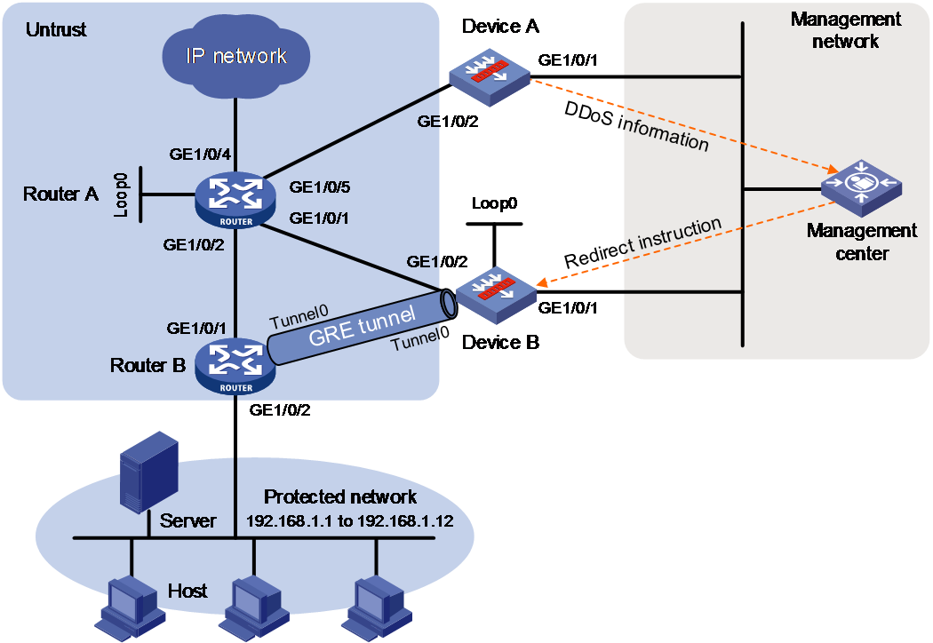
Procedure
1. Configure VLANs:
# Create VLAN 1000.
<Device> system-view
[Device] vlan 100
[Device-vlan100] quit
# Assign GigabitEthernet 1/0/2 and GigabitEthernet 1/0/3 to VLAN 100 as access interfaces.
[Device] interface gigabitethernet 1/0/2
[Device-GigabitEthernet1/0/2] port link-mode bridge
[Device-GigabitEthernet1/0/2] port link-type access
[Device-GigabitEthernet1/0/2] port access vlan 100
[Device-GigabitEthernet1/0/2] quit
[Device] interface gigabitethernet 1/0/3
[Device-GigabitEthernet1/0/3] port link-mode bridge
[Device-GigabitEthernet1/0/3] port link-type access
[Device-GigabitEthernet1/0/3] port access vlan 100
[Device-GigabitEthernet1/0/3] quit
2. Assign IP addresses to interfaces:
# Assign an IP address to .
[Device] interface gigabitethernet 1/0/1
[Device-GigabitEthernet1/0/1] ip address 10.0.0.2 255.255.255.0
[Device-GigabitEthernet1/0/1] quit
# Assign IP addresses to other interfaces in the same way. (Details not shown.)
3. Add interfaces to security zones.
[Device] security-zone name management
[Device-security-zone-Management] import interface gigabitethernet 1/0/1
[Device-security-zone-Management] quit
4. Configure DDoS attack protection:
# Specify the inline deployment mode for the device.
[Device] anti-ddos cleaner deploy-mode inline
# Add a global static blacklist entry to block traffic from IP address 1.1.1.1.
[Device] anti-ddos blacklist ip 1.1.1.1 32
# Add a global static whitelist entry to permit traffic from IP address 1.1.1.2 to pass through.
[Device] anti-ddos whitelist ip 1.1.1.2 32
Configure an anti-DDoS zone and Add an IP address range to the zone.
[Device] anti-ddos zone id 2
[Device-anti-ddos-zone-id-2] ip-range 192.168.1.1 192.168.1.12
# Configure an anti-DDoS zone-based static blacklist entry to block packets from 1.1.1.3.
[Device] zone-blacklist ip 1.1.1.3 32
# Configure an anti-DDoS zone-based static whitelist entry to permit packets from 1.1.1.4.
[Device] zone-whitelist ip 1.1.1.4 32
# Enable UDP flood attack detection and set the detection threshold to 2000 pps.
[Device-anti-ddos-zone-id-2] udp-flood detection threshold packet-based 2000
# Enable threshold learning.
[Device-anti-ddos-zone-id-2] threshold-learning enable
[Device-anti-ddos-zone-id-2] quit
# Specify 10.0.0.2 as the source IP address of DDoS protection logs.
[Device] anti-ddos log-local-ip ip 10.0.0.2
# Specify 10.0.0.3 as the destination IP address and 10083 as the port number of DDoS protection logs.
[Device] anti-ddos log-server-ip ip 10.0.0.3 port 10083
# Specify the port that connects the device to the management center to be excluded from DDoS protection.
[Device] anti-ddos out-of-band interface gigabitethernet 1/0/1
Verifying the configuration
# Verify the configuration of anti-DDoS zone 2.
[Device] display anti-ddos zone configuration id 2
Anti-DDoS zone configuration information
Zone ID : 2
Zone name :
IP range configuration:
Start IP End IP
192.168.1.1 192.168.1.12
Flood detection configuration:
Flood type Thres(pps/Mbps)
UDP 2000 pps
Source verification configuration:
Type Status
TCP Disabled
HTTP Disabled
DNS query Disabled
DNS reply Disabled
SIP Disabled
Fingerprint configuration:
Type GroupID
IPv4 1
Threshold Learning: Enabled
Black/White list:
Type IP MaskLength
Black 1.1.1.3 32
White 1.1.1.4 32
# Verify DDoS protection statistics when the device detects a UDP flood attack destined for a protected address.
[Device] display anti-ddos statistics destination-ip ipv4 192.168.1.11
Slot 1:
IP address packet-type Input(bps) Output(bps) Input(pps) Output(pps)
192.168.1.11 UDP 17507820 29940 291797 499
Example: Configuring DDoS protection (one-arm deployment of cleaning device)
Network configuration
As shown in Figure 12 and Table 1, the internal network has a high egress bandwidth and the core device (Router A) at the egress of the network can be connected with other devices deployed in one-arm mode. To protect important services of the internal network against from DDoS attacks, deploy a detection device and cleaning device to meet the following requirements:
· Deploy a detection device (Router A) and cleaning device (Device B) in the one-arm mode at the network egress to provide real-time DDoS attack protection for bidirectional traffic.
· Configure protection policies for different services to prevent the hosts in the IP address range of 192.168.1.1 to 192.168.1.12 from DDoS attacks.
· Configure BGP redirection and GRE injection to dynamically redirect attack traffic from Router A to Device B and then inject clean traffic back to Router B through the GRE tunnel.
· the uplink and downlink interfaces on the device to operate in Layer mode without changing the Layer 3 network topology.

Table 1 Interface and IP address assignment
|
Device |
Interface |
IP address |
Device |
Interface |
IP address |
|
Device A |
GE1/0/1 |
10.0.0.1/24 |
Router A |
GE1/0/1 |
2.0.0.1/24 |
|
Device A |
GE1/0/2 |
1.0.0.2/24 |
Router A |
GE1/0/2 |
3.0.0.1/24 |
|
Device B |
GE1/0/1 |
10.0.0.2/24 |
Router A |
GE1/0/5 |
1.0.0.1/24 |
|
Device B |
GE1/0/2 |
2.0.0.2/24 |
Router A |
Loop0 |
1.1.1.1/32 |
|
Device B |
Loop0 |
2.2.2.2/32 |
Router B |
GE1/0/1 |
3.0.0.2/24 |
|
Device B |
Tunnel0 |
10.1.0.2/24 |
Router B |
GE1/0/2 |
192.168.1.1/24 |
|
Management Center |
GE1/0/1 |
10.0.0.3/24 |
Router B |
Tunnel0 |
10.1.0.1/24 |
Configuring Device A
1. Assign IP addresses to interfaces:
# Assign an IP address to GigabitEthernet 1/0/1.
<DeviceA> system-view
[DeviceA] interface gigabitethernet 1/0/1
[DeviceA-GigabitEthernet1/0/1] ip address 10.0.0.1 255.255.255.0
[DeviceA-GigabitEthernet1/0/1] quit
# Assign IP addresses to other interfaces in the same way. (Details not shown.)
2. Add interfaces to security zones.
[DeviceA] security-zone name management
[DeviceA-security-zone-Management] import interface gigabitethernet 1/0/1
[DeviceA-security-zone-Management] quit
[DeviceA] security-zone name untrust
[DeviceA-security-zone-Untrust] import interface gigabitethernet 1/0/2
[DeviceA-security-zone-Untrust] quit
3. Configure a security policy to allow the device to detect the traffic from security zone untrust.
[DeviceA] security-policy ip
[DeviceA-security-policy-ip] rule name from-untrust
[DeviceA-security-policy-ip-1-from-untrust] source-zone untrust
[DeviceA-security-policy-ip-1-from-untrust] action pass
[DeviceA-security-policy-ip-1-from-untrust] quit
[DeviceA-security-policy-ip] quit
4. Configure DDoS attack protection:
# Specify the DFI-based DDoS attack detection mode.
[DeviceA] anti-ddos detection-mode flow
# Specify a flow agent with IP address 1.1.1.1 and destination port number 9999, and set the packet format to NetFlow and sampling rate to 1000.
[DeviceA] anti-ddos flow-agent ip 1.1.1.1 port 9999 flow-type netflow sampling-rate 1000
# Configure an anti-DDoS zone and add an IP address range to the zone.
[DeviceA] anti-ddos zone id 2
[DeviceA-anti-ddos-zone-id-2] ip-range 192.168.1.1 192.168.1.12
# Enable flood attack detection for various types of flood attacks and set the detection thresholds.
[DeviceA-anti-ddos-zone-id-2] dns-query-flood detection threshold packet-based 2000
[DeviceA-anti-ddos-zone-id-2] dns-reply-flood detection threshold packet-based 2000
[DeviceA-anti-ddos-zone-id-2] http-flood detection threshold packet-based 2000
[DeviceA-anti-ddos-zone-id-2] sip-flood detection threshold packet-based 2000
[DeviceA-anti-ddos-zone-id-2] syn-flood detection threshold packet-based 2000
[DeviceA-anti-ddos-zone-id-2] bandwidth-detection destination-ip threshold 20
[DeviceA-anti-ddos-zone-id-2] quit
# Specify 10.0.0.1 as the source IP address of DDoS protection logs.
[DeviceA] anti-ddos log-local-ip ip 10.0.0.1
# Specify 10.0.0.3 as the destination IP address and 10083 as the destination port number of DDoS protection logs.
[DeviceA] anti-ddos log-server-ip ip 10.0.0.3 port 10083
# Specify the port that connects the device to the management center to be excluded from DDoS protection.
[DeviceA] anti-ddos out-of-band interface gigabitethernet 1/0/1
Configuring Device B
1. Assign IP addresses to interfaces:
# Assign an IP address to GigabitEthernet 1/0/1.
<DeviceB> system-view
[DeviceB] interface gigabitethernet 1/0/1
[DeviceB-GigabitEthernet1/0/1] ip address 10.0.0.2 255.255.255.0
[DeviceB-GigabitEthernet1/0/1] quit
# Assign IP addresses to other interfaces in the same way. (Details not shown.)
2. Add interfaces to security zones.
[DeviceB] security-zone name management
[DeviceB-security-zone-Management] import interface gigabitethernet 1/0/1
[DeviceB-security-zone-Management] quit
[DeviceB] security-zone name untrust
[DeviceB-security-zone-Untrust] import interface gigabitethernet 1/0/2
[DeviceB-security-zone-Untrust] import interface tunnel 0
[DeviceB-security-zone-Untrust] quit
3. Configure a security policy to allow Device B to allow redirected traffic to be injected back.
[DeviceB] security-policy ip
[DeviceB-security-policy-ip] rule name untrust-untrust
[DeviceB-security-policy-ip-1-untrust-untrust] source-zone untrust
[DeviceB-security-policy-ip-2-untrust-untrust] destination-zone untrust
[DeviceB-security-policy-ip-1-untrust-untrust] destination-ip-range 192.168.1.1 192.168.1.12
[DeviceB-security-policy-ip-1-untrust-untrust] action pass
[DeviceB-security-policy-ip-1-untrust-untrust] quit
[DeviceB-security-policy-ip] quit
4. Configure BGP redirection:
# Configure OSPF 1 for communication between loopback interfaces.
[DeviceB] ospf 1
[DeviceB-ospf-1] area 0
[DeviceB-ospf-1-area-0.0.0.0] network 2.2.2.2 0.0.0.0
[DeviceB-ospf-1-area-0.0.0.0] network 2.0.0.0 0.0.0.255
[DeviceB-ospf-1-area-0.0.0.0] quit
[DeviceB-ospf-1] quit
# Configure a routing policy.
[DeviceB] route-policy comm_no_advertise permit node 0
[DeviceB-route-policy-comm_no_advertise-0] apply community no-advertise
[DeviceB-route-policy-comm_no_advertise-0] quit
# Create a BGP instance and configure BGP peer parameters.
[DeviceB] bgp 65000
[DeviceB-bgp-default] router-id 2.2.2.2
[DeviceB-bgp-default] peer 1.1.1.1 as-number 65000
[DeviceB-bgp-default] peer 1.1.1.1 connect-interface loopback 0
[DeviceB-bgp-default] address-family ipv4 unicast
[DeviceB-bgp-default-ipv4] peer 1.1.1.1 enable
[DeviceB-bgp-default-ipv4] peer 1.1.1.1 route-policy comm_no_advertise export
[DeviceB-bgp-default-ipv4] peer 1.1.1.1 advertise-community
[DeviceB-bgp-default-ipv4] import-route guard
[DeviceB-bgp-default-ipv4] quit
[DeviceB-bgp-default] quit
5. Configure GRE injection:
# Create GRE/IPv4 tunnel interface Tunnel 0 and configure GRE tunnel parameters.
[DeviceB] interface tunnel 0 mode gre
[DeviceB-Tunnel0] ip address 10.1.0.2 24
[DeviceB-Tunnel0] source 2.0.0.2
[DeviceB-Tunnel0] destination 3.0.0.2
[DeviceB-Tunnel0] quit
# Configure a static route, whose destination address is 192.168.1.0/24 and the next hop is Tunnel 0.
[DeviceB] ip route-static 192.168.1.0 24 tunnel 0
6. Configure DDoS attack protection:
# Specify the one-arm deployment mode for the device.
[DeviceB] anti-ddos cleaner deploy-mode out-of-path
# Configure an anti-DDoS zone and add an IP address range to the zone.
[DeviceB] anti-ddos zone id 2
[DeviceB-anti-ddos-zone-id-2] ip-range 192.168.1.1 192.168.1.12
# Enable flood attack detection for various types of flood attacks and set the detection thresholds. This example uses threshold 2000 pps.
[DeviceB-anti-ddos-zone-id-2] dns-query-flood detection threshold packet-based 2000
[DeviceB-anti-ddos-zone-id-2] dns-reply-flood detection threshold packet-based 2000
[DeviceB-anti-ddos-zone-id-2] http-flood detection threshold packet-based 2000
[DeviceB-anti-ddos-zone-id-2] sip-flood detection threshold packet-based 2000
[DeviceB-anti-ddos-zone-id-2] syn-flood detection threshold packet-based 2000
[DeviceB-anti-ddos-zone-id-2] bandwidth-detection destination-ip threshold 20
# Enable source verification for various types of flood attacks.
[DeviceB-anti-ddos-zone-id-2] dns-query-flood defense source-verify
[DeviceB-anti-ddos-zone-id-2] dns-reply-flood defense source-verify
[DeviceB-anti-ddos-zone-id-2] http-flood defense source-verify
[DeviceB-anti-ddos-zone-id-2] sip-flood defense source-verify
[DeviceB-anti-ddos-zone-id-2] syn-flood defense source-verify
# Enable packet rate limiting, and set the thresholds for TCP traffic, UDP traffic, and IP traffic to 5 Mbps, 5 Mbps, and 10 Mbps, respectively.
[DeviceB-anti-ddos-zone-id-2] bandwidth-limit destination-ip type tcp max-rate 5
[DeviceB-anti-ddos-zone-id-2] bandwidth-limit destination-ip type udp max-rate 5
[DeviceB-anti-ddos-zone-id-2] bandwidth-limit destination-ip type total max-rate 10
[DeviceB-anti-ddos-zone-id-2] quit
# Specify 10.0.0.1 as the source IP address of DDoS protection logs.
[DeviceB] anti-ddos log-local-ip ip 10.0.0.2
# Specify 10.0.0.3 as the destination IP address and 10083 as the destination port number of DDoS protection logs.
[DeviceB] anti-ddos log-server-ip ip 10.0.0.3 port 10083
# Specify the port that connects the device to the management center to be excluded from DDoS protection.
[DeviceB] anti-ddos out-of-band interface gigabitethernet 1/0/1
Configuring Router A
1. Assign IP addresses to interfaces:
# Assign an IP address to GigabitEthernet 1/0/1.
<DeviceB> system-view
[DeviceB] interface gigabitethernet 1/0/1
[DeviceB-GigabitEthernet1/0/1] ip address 10.0.0.2 255.255.255.0
[DeviceB-GigabitEthernet1/0/1] quit
# Assign IP addresses to other interfaces in the same way. (Details not shown.)
2. Configure OSPF:
[RouterA] ospf 1
[RouterA-ospf-1] area 0
[RouterA-ospf-1-area-0.0.0.0] network 1.1.1.1 0.0.0.0
[RouterA-ospf-1-area-0.0.0.0] network 2.0.0.0 0.0.0.255
[RouterA-ospf-1-area-0.0.0.0] network 3.0.0.0 0.0.0.255
[RouterA-ospf-1-area-0.0.0.0] quit
[RouterA-ospf-1] quit
3. Configure BGP:
[RouterA] bgp 65000
[RouterA-bgp-default] router-id 1.1.1.1
[RouterA-bgp-default] peer 2.2.2.2 as-number 65000
[RouterA-bgp-default] peer 2.2.2.2 connect-interface loopback 0
[RouterA-bgp-default] address-family ipv4 unicast
[RouterA-bgp-default-ipv4] peer 2.2.2.2 enable
Configuring Router B
1. Assign IP addresses to interfaces:
# Assign an IP address to GigabitEthernet 1/0/1.
<DeviceB> system-view
[DeviceB] interface gigabitethernet 1/0/1
[DeviceB-GigabitEthernet1/0/1] ip address 10.0.0.2 255.255.255.0
[DeviceB-GigabitEthernet1/0/1] quit
# Assign IP addresses to other interfaces in the same way. (Details not shown.)
2. Configure OSPF:
[RouterB] ospf 1
[RouterB-ospf-1] area 0
[RouterB-ospf-1-area-0.0.0.0] network 3.0.0.0 0.0.0.255
[RouterB-ospf-1-area-0.0.0.0] quit
[RouterB-ospf-1] quit
3. Configure GRE tunneling:
[RouterB] interface tunnel 0 mode gre
[RouterB-Tunnel0] ip address 10.1.0.1 24
[RouterB-Tunnel0] source 3.0.0.2
[RouterB-Tunnel0] destination 2.0.0.2
Verifying the configuration
# On Device A, verify packet statistics about the flow agent.
[DeviceA] display anti-ddos flow-agent statistics ip 10.0.1.1 port 1200 slot 1
Slot 1:
NetFlow V5 statistics information:
Pkts:206
Records:412
DropRecords:0
NetFlow V9 statistics information:
Pkts:38
Records:428
TemplateRecords:12
DataRecords:192
DropRecords:224
# On Device B, verify the configuration of anti-DDoS zone 2.
[DeviceB] display anti-ddos zone configuration id 2
Anti-DDoS zone configuration information
Zone ID : 2
Zone name :
IP range configuration:
Start IP End IP
192.168.1.1 192.168.1.12
Flood detection configuration:
Flood type Thres(pps/Mbps)
DNS query 2000 pps
DNS reply 2000 pps
HTTP 2000 pps
SYN 2000 pps
SIP 2000 pps
Source verification configuration:
Type Status
TCP Enabled
HTTP Enabled
DNS query Enabled
DNS reply Enabled
SIP Enabled
Bandwidth configuration:
bandwidth-detection destination-ip threshold: 20
bandwidth-limit destination-ip max-rate: 10
bandwidth-limit destination-ip type tcp max-rate 5
bandwidth-limit destination-ip type udp max-rate 5
Fingerprint configuration:
Type GroupID
Threshold Learning: Disabled
Black/White list:
Type IP MaskLength
# Display information about the protected IP addresses on Device B when a DDoS attack is detected.
[DeviceB] display anti-ddos source-verify dns-query protected ip
IP address Port Type Requested Trusted
192.168.1.10 53 Dynamic 20 12
[DeviceB] display anti-ddos source-verify dns-reply protected ip
IP address Port Type Requested Trusted
192.168.1.9 53 Dynamic 18 7
[DeviceB] display anti-ddos source-verify http protected ip
IP address Port Type Requested Trusted
192.168.1.8 80 Dynamic 6 3
[DeviceB] display anti-ddos source-verify sip protected ip
IP address Port Type Requested Trusted
192.168.1.7 5060 Dynamic 15 9
[DeviceB] display anti-ddos source-verify syn protected ip
IP address Port Type Requested Trusted
192.168.1.6 any Dynamic 25 20
# On Device B, verify DDoS protection statistics when the device detects an IP traffic attack destined for a protected address.
[DeviceB] display anti-ddos statistics destination-ip ipv4 192.168.1.11
Slot 1:
IP address packet-type Input(bps) Output(bps) Input(pps) Output(pps)
192.168.1.11 IP 17507880 1250000 291798 156200
# On Device B, display rate limiting statistics about protected IP addresses.
[DeviceB] display anti-ddos statistics bandwidth-limit destination-ip ipv4 192.168.1.11
Slot 1:
Type Input(bps) Output(bps) Input(pps) Output(pps) Threshold(Mbps)
TCP 435681 435681 108920 108920 5
UDP 865355 655360 43622 43622 5
IP 1250000 1250000 156200 156200 10
