- Table of Contents
-
- 05-Network Connectivity
- 00-Preface
- 01-About the network connectivity configuration guide
- 02-MAC address table configuration
- 03-Ethernet link aggregation configuration
- 04-Port isolation configuration
- 05-VLAN configuration
- 06-Loop detection configuration
- 07-Spanning tree configuration
- 08-LLDP configuration
- 09-Layer 2 forwarding configuration
- 10-VLAN termination configuration
- 11-PPP configuration
- 12-L2TP configuration
- 13-Modem management configuration
- 14-3G and 4G modem management configuration
- 15-ARP configuration
- 16-IP addressing configuration
- 17-DHCP configuration
- 18-DHCPv6 configuration
- 19-DNS configuration
- 20-NAT configuration
- 21-IP performance optimization configuration
- 22-IPv6 basics configuration
- 23-GRE configuration
- 24-Tunneling configuration
- 25-IP forwarding basics configuration
- 26-Basic IP routing configuration
- 27-Static routing configuration
- 28-IPv6 static routing configuration
- 29-Policy-based routing configuration
- 30-IPv6 policy-based routing configuration
- 31-RIP configuration
- 32-RIPng configuration
- 33-Multicast overview
- 34-IGMP snooping configuration
- 35-MLD snooping configuration
- Related Documents
-
| Title | Size | Download |
|---|---|---|
| 12-L2TP configuration | 240.39 KB |
Contents
L2TP message types and encapsulation structure
L2TP tunneling modes and tunnel establishment process
Restrictions: Hardware compatibility with L2TP
Restrictions: Command and hardware compatibility
Configuring basic L2TP capabilities
Configuring an LNS to accept L2TP tunneling requests from an LAC
Configuring user authentication on an LNS
Configuring AAA authentication on an LNS
Configuring optional L2TP parameters
Configuring L2TP tunnel authentication
Setting the DSCP value of L2TP packets
Display and maintenance commands for L2TP
Failure to access the private network
Configuring L2TP
About L2TP
The Layer 2 Tunneling Protocol (L2TP) is a Virtual Private Dialup Network (VPDN) tunneling protocol. L2TP sets up point-to-point tunnels across a public network (for example, the Internet) and transmits encapsulated PPP frames (L2TP packets) over the tunnels. With L2TP, remote users can access the private networks through L2TP tunnels after connecting to a public network by using PPP.
As a Layer 2 VPN technology, L2TP provides a secure, cost-effective solution for remote users to access private networks.
Typical L2TP networking
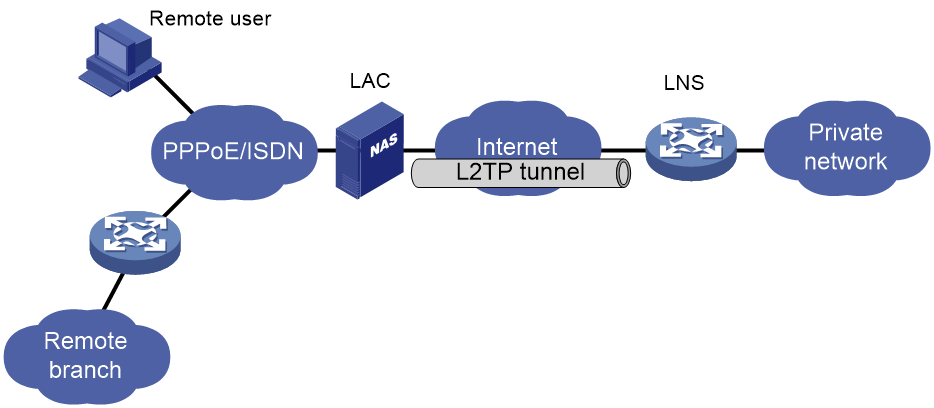
As shown in Figure 1, a typical L2TP network has the following components:
· Remote system—A remote system is usually a remote user's host or a remote branch's device that needs to access the private network.
· LAC—An L2TP access concentrator (LAC) is both PPP and L2TP capable. It is usually a network access server (NAS) located at a local ISP, which provides access services mainly for PPP users.
An LAC is an endpoint of an L2TP tunnel and lies between an LNS and a remote system. It encapsulates packets received from a remote system by using L2TP and then sends the encapsulated packets to the LNS. It decapsulates packets received from the LNS and then sends the decapsulated packets to the intended remote system.
· LNS—An L2TP network server (LNS) is both PPP and L2TP capable. It is usually an edge device on an enterprise network.
An LNS is the other endpoint of an L2TP tunnel. It is the logical termination point of a PPP session tunneled by the LAC. L2TP extends the termination point of a PPP session from a NAS to an LNS by establishing a tunnel.
L2TP message types and encapsulation structure
L2TP uses the following types of messages:
· Control messages—Used to establish, maintain, and delete L2TP tunnels and sessions. Control messages are transmitted over a reliable control channel, which supports flow control and congestion control.
· Data messages—Used to encapsulate PPP frames, as shown in Figure 2. Data messages are transmitted over an unreliable data channel and are not retransmitted when packet loss occurs. Data messages can use sequence numbers to reorder packets that are disordered during transport.
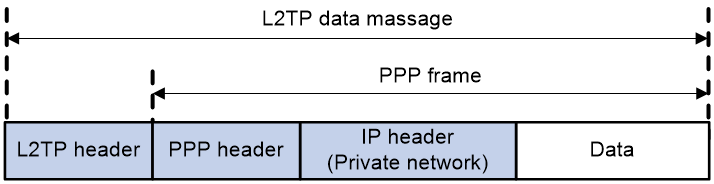
As shown in Figure 3, both control messages and data messages are encapsulated in UDP datagrams.
Figure 3 L2TP encapsulation structure
![]()
L2TP tunnel and session
An L2TP tunnel is a virtual point-to-point connection between an LAC and an LNS. Multiple L2TP tunnels can be established between an LNS and an LAC. An L2TP tunnel can carry one or more L2TP sessions. Each L2TP session corresponds to a PPP session and is multiplexed on an L2TP tunnel. An L2TP session is established between the LAC and LNS when an end-to-end PPP session is established between a remote system and the LNS. Data frames for the PPP session are transmitted over the tunnel between the LAC and LNS.
L2TP tunneling modes and tunnel establishment process
L2TP tunneling modes include NAS-initiated and client-initiated.
NAS-initiated tunneling mode
As shown in Figure 4, a remote system dials in to the LAC through a PPPoE network. The LAC initiates a tunneling request to the LNS over the Internet.
Figure 4 NAS-initiated tunneling mode
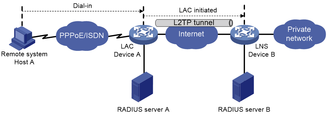
A NAS-initiated tunnel has the following characteristics:
· The remote system only needs to support PPP, and it does not need to support L2TP.
· Authentication and accounting of the remote system can be implemented on the LAC or LNS.
Figure 5 NAS-initiated tunnel establishment process
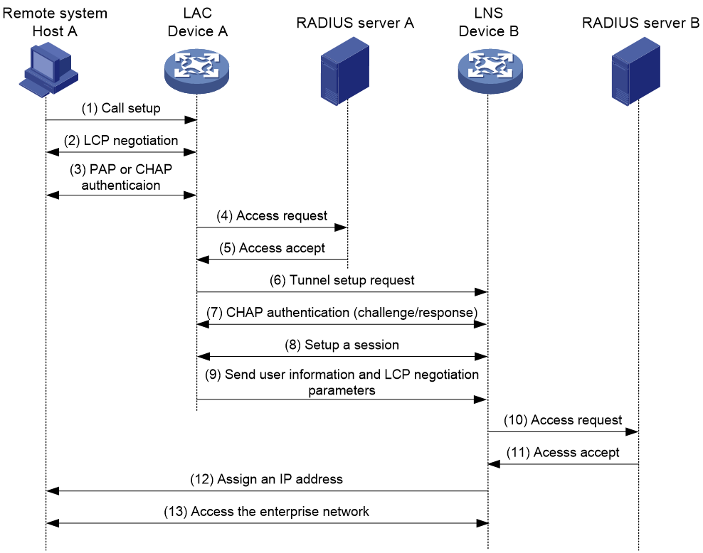
As shown in Figure 5, the following workflow is used to establish a NAS-initiated tunnel:
1. A remote system (Host A) initiates a PPP connection to the LAC (Device A).
2. The remote system and LAC perform PPP LCP negotiation.
3. The LAC authenticates PPP user information of Host A by using PAP or CHAP.
4. The LAC sends the authentication information (username and password) to its RADIUS server (RADIUS server A) for authentication.
5. RADIUS server A authenticates the user and returns the result.
6. The LAC initiates an L2TP tunneling request to the LNS (Device B) when the following conditions exist:
¡ The user passes the authentication.
¡ The user is determined to be an L2TP user according to the username or the ISP domain to which the user belongs.
7. If tunnel authentication is needed, the LAC and LNS send CHAP challenge messages to authenticate each other before successfully establishing an L2TP tunnel.
8. The LAC and LNS negotiate to establish L2TP sessions.
9. The LAC sends PPP user information and PPP negotiation parameters to the LNS.
10. The LNS sends the authentication information to its RADIUS server (RADIUS server B) for authentication.
11. RADIUS server B authenticates the user and returns the result.
12. If the user passes the authentication, the LNS assigns a private IP address to the remote system (Host A).
13. The PPP user can access internal resources of the enterprise.
In steps 12 and 13, the LAC forwards packets for the remote system and LNS. Host A and LAC exchange PPP frames, and the LAC and LNS exchange L2TP packets.
Client-initiated tunneling mode
As shown in Figure 6, a remote system running L2TP (LAC client) has a public IP address to communicate with the LNS through the Internet. The LAC client can directly initiate a tunneling request to the LNS without any dedicated LAC devices.
Figure 6 Client-initiated tunneling mode
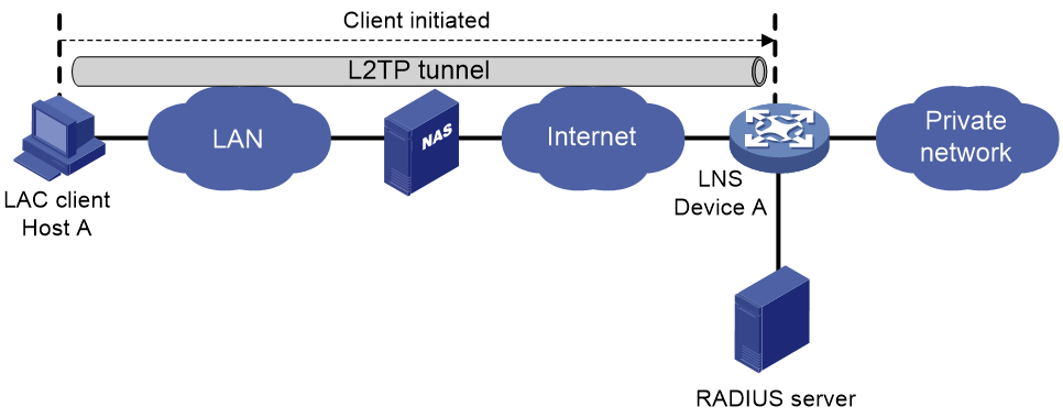
A client-initiated tunnel has the following characteristics:
· A client-initiated tunnel has higher security because it is established between a remote system and the LNS.
· The remote system must support L2TP and be able to communicate with the LNS. This causes poor expandability.
As shown in Figure 7, the workflow for establishing a client-initiated tunnel is similar to that for establishing a NAS-initiated tunnel. (Details not shown.)
Figure 7 Client-initiated tunnel establishment process

L2TP features
· Flexible identity authentication mechanism and high security—L2TP by itself does not provide security for connections. However, it has all the security features of PPP and allows for PPP authentication (CHAP or PAP). L2TP can also cooperate with IPsec to improve security for tunneled data.
· Multiprotocol transmission—L2TP tunnels PPP frames, which can be used to encapsulate packets of multiple network layer protocols.
· RADIUS authentication—An LAC or LNS can send the username and password of a remote user to a RADIUS server for authentication.
· Private address allocation—An LNS can dynamically allocate private addresses to remote users. This facilitates address allocation for private internets (RFC 1918) and improves security.
· Flexible accounting—Accounting can be simultaneously performed on the LAC and LNS. This allows bills to be generated on the ISP side and charging and auditing to be processed on the enterprise gateway. L2TP can provide accounting data, including inbound and outbound traffic statistics (in packets and bytes) and the connection's start time and end time. The AAA server uses these data for flexible accounting.
· Reliability—L2TP supports LNS backup. When the connection to the primary LNS is torn down, an LAC can establish a new connection to a secondary LNS. This redundancy enhances the reliability of L2TP services.
· Issuing tunnel attributes by RADIUS server to LAC—In NAS-initiated mode, the tunnel attributes can be issued by the RADIUS server to the LAC. For the LAC to receive these attributes, enable L2TP and configure remote AAA authentication for PPP users on the LAC.
When an L2TP user dials in to the LAC, the LAC as the RADIUS client sends the user information to the RADIUS server. The RADIUS server authenticates the PPP user, returns the result to the LAC, and issues L2TP tunnel attributes for the PPP user to the LAC. The LAC then sets up an L2TP tunnel and sessions based on the issued L2TP tunnel attributes.
Table 1 Tunnel attributes that can be issued by the RADIUS server
|
Attribute number |
Attribute name |
Description |
|
64 |
Tunnel-Type |
Tunnel type, which can only be L2TP. |
|
65 |
Tunnel-Medium-Type |
Transmission medium type for the tunnel, which can only be IPv4. |
|
67 |
Tunnel-Server-Endpoint |
IP address of the LNS. |
|
69 |
Tunnel-Password |
Key used to authenticate a peer of the tunnel. |
|
81 |
Tunnel-Private-Group-ID |
Group ID for the tunnel. The LAC sends this value to the LNS for the LNS to perform an operation accordingly. |
|
82 |
Tunnel-Assignment-ID |
Assignment ID for the tunnel. It is used to indicate the tunnel to which a session is assigned. L2TP users with the same Tunnel-Assignment-ID, Tunnel-Server-Endpoint, and Tunnel-Password attributes share an L2TP tunnel. |
|
90 |
Tunnel-Client-Auth-ID |
Tunnel name. It is used to indicate the local tunnel. |
The RADIUS server can issue only one set of the L2TP tunnel attributes in a RADIUS packet.
The RADIUS-issued tunnel attributes override the tunnel attributes manually configured on the LAC, but not vice versa.
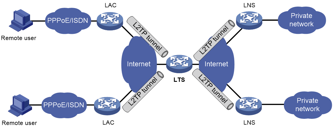
· L2TP tunnel switching—Also called multihop L2TP tunneling. As shown in Figure 8, the Layer 2 tunnel switch (LTS) terminates L2TP packets from each LAC as an LNS. It then sends these packets to a destination LNS as an LAC.
L2TP tunnel switching has the following features:
¡ Simplified configuration and deployment—When LACs and LNSs are in different management domains:
- All LACs consider the LTS as an LNS and do not need to differentiate LNSs on the network.
- All LNSs consider the LTS as an LAC and are not affected by the addition or deletion of LACs.
¡ L2TP tunnel sharing—Different users can share the same L2TP tunnel between the LAC and the LTS. The LTS distributes data of different users to different LNSs.
Figure 8 L2TP tunnel switching network diagram
L2TP-based EAD
EAD authenticates PPP users that pass the access authentication. PPP users that pass EAD authentication can access network resources. PPP users that fail EAD authentication can only access the resources in the quarantine areas.
EAD uses the following procedure:
1. The iNode client uses L2TP to access the LNS. After the client passes the PPP authentication, the CAMS/IMC server assigns isolation ACLs to the LNS. The LNS uses the isolation ACLs to filter incoming packets.
2. After the IPCP negotiation, the LNS sends the IP address of the CAMS/IMC server to the iNode client. The server IP address is permitted by the isolation ACLs.
3. The CAMS/IMC server authenticates the iNode client and performs security check for the iNode client. If the iNode client passes security check, the CAMS/IMC server assigns security ACLs for the iNode client to the LNS. The iNode client can access network resources.
Protocols and standards
· RFC 1661, The Point-to-Point Protocol (PPP)
· RFC 1918, Address Allocation for Private Internets
· RFC 2661, Layer Two Tunneling Protocol "L2TP"
· RFC 2868, RADIUS Attributes for Tunnel Protocol Support
Restrictions: Hardware compatibility with L2TP
|
Hardware series |
Models |
Product code |
L2TP compatibility |
|
WX1800H series |
WX1804H-PWR |
EWP-WX1804H-PWR-CN |
Yes |
|
WX2500H series |
WX2508H-PWR-LTE WX2510H-PWR WX2510H-F-PWR WX2540H WX2540H-F WX2560H |
EWP-WX2508H-PWR-LTE EWP-WX2510H-PWR EWP-WX2510H-F-PWR EWP-WX2540H EWP-WX2540H-F EWP-WX2560H |
Yes |
|
MAK series |
MAK204 MAK206 |
EWP-MAK204 EWP-MAK206 |
Yes |
|
WX3000H series |
WX3010H WX3010H-X-PWR WX3010H-L-PWR WX3024H WX3024H-L-PWR WX3024H-F |
EWP-WX3010H EWP-WX3010H-X-PWR EWP-WX3010H-L-PWR EWP-WX3024H EWP-WX3024H-L-PWR EWP-WX3024H-F |
Yes: · WX3010H · WX3010H-X-PWR · WX3024H · WX3024H-F No: · WX3010H-L-PWR · WX3024H-L-PWR |
|
WX3500H series |
WX3508H WX3508H WX3510H WX3510H WX3520H WX3520H-F WX3540H WX3540H |
EWP-WX3508H EWP-WX3508H-F EWP-WX3510H EWP-WX3510H-F EWP-WX3520H EWP-WX3520H-F EWP-WX3540H EWP-WX3540H-F |
Yes |
|
WX5500E series |
WX5510E WX5540E |
EWP-WX5510E EWP-WX5540E |
Yes |
|
WX5500H series |
WX5540H WX5560H WX5580H |
EWP-WX5540H EWP-WX5560H EWP-WX5580H |
Yes |
|
Access controller modules |
LSUM1WCME0 EWPXM1WCME0 LSQM1WCMX20 LSUM1WCMX20RT LSQM1WCMX40 LSUM1WCMX40RT EWPXM2WCMD0F EWPXM1MAC0F |
LSUM1WCME0 EWPXM1WCME0 LSQM1WCMX20 LSUM1WCMX20RT LSQM1WCMX40 LSUM1WCMX40RT EWPXM2WCMD0F EWPXM1MAC0F |
Yes |
|
Hardware series |
Models |
Product code |
L2TP compatibility |
|
WX1800H series |
WX1804H-PWR WX1810H-PWR WX1820H WX1840H |
EWP-WX1804H-PWR EWP-WX1810H-PWR EWP-WX1820H EWP-WX1840H-GL |
Yes |
|
WX3800H series |
WX3820H WX3840H |
EWP-WX3820H-GL EWP-WX3840H-GL |
No |
|
WX5800H series |
WX5860H |
EWP-WX5860H-GL |
No |
Restrictions: Command and hardware compatibility
The WX1800H series, WX2500H series, and WX3000H access controllers do not support parameters or commands that are available only in IRF mode.
Prerequisites for L2TP
When you configure L2TP, perform the following tasks:
1. Determine the network devices needed according to the networking environment.
¡ For NAS-initiated mode and LAC-auto-initiated mode, configure both the LAC and the LNS.
¡ For client-initiated mode, you only need to configure the LNS.
2. Configure the devices based on the intended role (LAC or LNS) on the network.
L2TP tasks at a glance
LNS tasks at a glance
1. Configuring basic L2TP capabilities
¡ (Optional.) Configuring a VA pool
¡ Configuring an LNS to accept L2TP tunneling requests from an LAC
¡ (Optional.) Configuring user authentication on an LNS
¡ (Optional.) Configuring AAA authentication on an LNS
3. (Optional) Configuring optional L2TP parameters
¡ Configuring L2TP tunnel authentication
¡ Enabling session flow control
¡ Setting the DSCP value of L2TP packets
¡ Setting the TSA ID of the LTS
Perform this task to use the security policy server to perform further security check for users that pass the L2TP authentication.
Configuring basic L2TP capabilities
About this task
Basic L2TP capability configuration includes the following tasks:
· Enabling L2TP—L2TP must be enabled for L2TP configurations to take effect.
· Creating an L2TP group—An L2TP group is intended to represent a group of parameters. This enables not only flexible L2TP configuration on devices, but also one-to-one and one-to-many networking applications for LACs and LNSs. An L2TP group has local significance only. However, the relevant settings of the L2TP groups on the LAC and LNS must match. For example, the local tunnel name configured on the LAC must match the tunnel peer name configured on the LNS.
· Configuring the local tunnel name—The local tunnel name identifies the tunnel at the local end during tunnel negotiation between an LAC and an LNS.
Procedure
1. Enter system view.
system-view
2. Enable L2TP.
l2tp enable
By default, L2TP is disabled.
3. Create an L2TP group, specify its mode, and enter its view.
l2tp-group group-number mode { lac | lns }
Specify the mode as lac on the LAC side and as lns on the LNS side.
4. Specify the local tunnel name.
tunnel name name
By default, the device name is used.
The local tunnel name configured on the LAC must match the tunnel peer name configured on the LNS.
Configuring an LNS
Creating a VT interface
After an L2TP session is established, a virtual access (VA) interface is needed for data exchange with the peer. The system will dynamically create VA interfaces based on the parameters of the virtual template (VT) interface. To configure an LNS, first create a VT interface and configure the following parameters for it:
· Interface IP address.
· Authentication mode for PPP users.
· IP addresses allocated by the LNS to PPP users.
For information about configuring VT interfaces, see PPP configuration and IP addressing configuration in Network Connectivity Configuration Guide.
Configuring a VA pool
About this task
A VA pool contains a group of VA interfaces. You can configure a VA pool to improve the performance of establishing or terminating L2TP connections. The LNS selects a VA interface from the pool for a requesting user and releases the VA interface when the user goes offline. When a VA pool is exhausted, the system creates a VA interface for an L2TP connection and deletes it when the user goes offline.
Restrictions and guidelines
A VT interface can be associated with only one VA pool. To change the capacity of a VA pool, delete the previous configuration and reconfigure the VA pool.
Creating or deleting a VA pool takes time. During the process of creating or deleting a VA pool, users can come online or go offline, but the VA pool does not take effect.
The system might create a VA pool that contains VA interfaces less than the specified number because of insufficient resources. To view the number of available VA interfaces and the current state of the VA pool, use the display l2tp va-pool command.
Create a VA pool with an appropriate capacity, because a VA pool occupies much system memory.
Deleting a VA pool does not log off the users who are using VA interfaces in the VA pool.
Procedure
1. Enter system view.
system-view
2. Create a VA pool.
l2tp virtual-template template-number va-pool va-volume
By default, no VA pool exists.
Configuring an LNS to accept L2TP tunneling requests from an LAC
About this task
When receiving a tunneling request, an LNS performs the following operations:
· Determines whether to accept the tunneling request by checking whether the name of the tunnel peer (LAC) matches the one configured.
· Determines the VT interface to be used for creating the VA interface.
Procedure
1. Enter system view.
system-view
2. Enter L2TP group view in LNS mode.
l2tp-group group-number [ mode lns ]
3. Configure the LNS to accept tunneling requests from an LAC and specify the VT interface to be used for tunnel setup.
¡ If the L2TP group number is 1:
allow l2tp virtual-template virtual-template-number [ remote remote-name ]
¡ If the L2TP group number is not 1:
allow l2tp virtual-template virtual-template-number remote remote-name
By default, an LNS denies tunneling requests from any LAC.
If the L2TP group number is 1, the remote remote-name option is optional. If you do not specify this option, the LNS accepts tunneling requests from any LAC.
Configuring user authentication on an LNS
About this task
An LNS can be configured to authenticate a user that has passed authentication on the LAC to increase security. In this case, the user is authenticated once on the LAC and once on the LNS. An L2TP tunnel can be established only when both authentications succeed.
An LNS provides the following authentication methods in ascending order of priority:
· Proxy authentication—The LNS uses the LAC as an authentication proxy. The LAC sends the LNS all user authentication information from users and the authentication method configured on the LAC itself. The LNS then checks the user validity according to the received information and the locally configured authentication method.
· Mandatory CHAP authentication—The LNS uses CHAP authentication to reauthenticate users who have passed authentication on the LAC.
· LCP renegotiation—The LNS ignores the LAC proxy authentication information and performs a new round of LCP negotiation with the user.
The LNS chooses an authentication method depending on your configuration.
· If you configure both LCP renegotiation and mandatory CHAP authentication, the LNS uses LCP renegotiation.
· If you configure only mandatory CHAP authentication, the LNS performs CHAP authentication for users after proxy authentication succeeds.
· If you configure neither LCP renegotiation nor mandatory CHAP authentication, the LNS uses the LAC for proxy authentication.
Restrictions and guidelines for user authentication on an LNS
This mandatory CHAP authentication and LCP renegotiation methods are effective only on NAS-initiated L2TP tunnels.
For mandatory CHAP authentication to take effect, you must also configure CHAP authentication for the PPP user on the VT interface of the LNS.
For the LNS not to accept LCP negotiation parameters, configure this feature to perform a new round of LCP negotiation between the LNS and the user. In this case, the LNS authenticates the user by using the authentication method configured on the corresponding VT interface.
Configuring mandatory CHAP authentication
1. Enter system view.
system-view
2. Enter L2TP group view in LNS mode.
l2tp-group group-number [ mode lns ]
3. Configure mandatory CHAP authentication.
mandatory-chap
By default, CHAP authentication is not performed on an LNS.
Some users might not support the authentication on the LNS. In this situation, do not enable this feature, because CHAP authentication on the LNS will fail.
4. Return to system view.
quit
5. Enter VT interface view and set the authentication type of PPP users to CHAP.
For more information about VT interfaces, see PPP configuration in Network Connectivity Configuration Guide.
Configuring LCP renegotiation
1. Enter system view.
system-view
2. Enter L2TP group view in LNS mode.
l2tp-group group-number [ mode lns ]
3. Configure the LNS to perform LCP renegotiation with users.
mandatory-lcp
By default, an LNS does not perform LCP renegotiation with users.
This command is effective only on NAS-initiated L2TP tunnels.
If you enable LCP renegotiation but configure no authentication for the corresponding VT interface, the LNS does not perform an additional authentication for users.
Configuring AAA authentication on an LNS
After you configure AAA authentication on an LNS, the LNS can authenticate the usernames and passwords of remote access users. If a user passes AAA authentication, the user can communicate with the LNS to access the private network.
Configure AAA authentication on the LNS in one of the following cases:
· LCP renegotiation is not configured in NAS-initiated mode.
· The VT interface is configured with PPP user authentication and LCP renegotiation is configured in NAS-initiated mode.
· The VT interface is configured with PPP user authentication in client-initiated mode or LAC-auto-initiated mode.
Configuring optional L2TP parameters
Configuring L2TP tunnel authentication
About this task
Tunnel authentication allows the LAC and LNS to authenticate each other. Either the LAC or the LNS can initiate a tunnel authentication request.
You can enable tunnel authentication on both sides or either side.
To ensure a successful tunnel establishment when tunnel authentication is enabled on both sides or either side, set the same non-null key on the LAC and the LNS. To set the tunnel authentication key, use the tunnel password command.
When neither side is enabled with tunnel authentication, the key settings of the LAC and the LNS do not affect the tunnel establishment.
Restrictions and guidelines
To ensure tunnel security, enable tunnel authentication.
Modifying the tunnel authentication key does not affect the normal communication of current tunnels. The tunnel authentication key change takes effect at next tunnel establishment.
Procedure
1. Enter system view.
system-view
2. Enter L2TP group view.
l2tp-group group-number [ mode { lac | lns } ]
3. Enable L2TP tunnel authentication.
tunnel authentication
By default, L2TP tunnel authentication is enabled.
4. Set the tunnel authentication key.
tunnel password { cipher | simple } string
By default, no key is set.
Setting the Hello interval
About this task
To check the connectivity of a tunnel, the LAC and LNS periodically send each other Hello packets. At receipt of a Hello packet, the LAC or LNS returns a response packet. If the LAC or LNS receives no response packets from the peer within the Hello interval, it retransmits the Hello packet. If it receives no response packets from the peer after transmitting the Hello packet five times, it considers the L2TP tunnel to be down.
Procedure
1. Enter system view.
system-view
2. Enter L2TP group view.
l2tp-group group-number [ mode { lac | lns } ]
3. Set the Hello interval.
tunnel timer hello hello-interval
The default setting is 60 seconds.
Enabling session flow control
About this task
This feature adds sequence numbers to transmitted packets and uses them to reorder packets arriving out of order and to detect lost packets.
This feature takes effect on both sent and received L2TP data messages. The L2TP sessions support this feature if either the LAC or LNS is enabled with this feature.
Procedure
1. Enter system view.
system-view
2. Enter L2TP group view.
l2tp-group group-number [ mode { lac | lns } ]
3. Enable the session flow control feature.
tunnel flow-control
By default, this feature is disabled.
Setting the DSCP value of L2TP packets
About this task
The DSCP field is the first 6 bits of the IP ToS byte. This field marks the priority of IP packets for forwarding. This feature sets the DSCP value for the IP packet when L2TP encapsulates a PPP frame into an IP packet.
Procedure
1. Enter system view.
system-view
2. Enter L2TP group view.
l2tp-group group-number [ mode { lac | lns } ]
3. Set the DSCP value of L2TP packets.
ip dscp dscp-value
The default setting is 0.
Setting the TSA ID of the LTS
About this task
To detect loops, the LTS compares the configured TSA ID with each TSA ID AVP in a received ICRQ packet.
· If a match is found, a loop exists. The LTS immediately tears down the session.
· If no match is found, the LTS performs the following operations:
¡ Encapsulates the configured TSA ID into a new TSA ID AVP.
¡ Appends it to the packet.
¡ Sends the packet to the next hop LTS.
Restrictions and guidelines
To avoid loop detection errors, make sure the TSA ID of each LTS is unique.
Procedure
1. Enter system view.
system-view
2. Set the TSA ID of the LTS and enable L2TP loop detection on the LTS.
l2tp tsa-id tsa-id
By default, the TSA ID of the LTS is not configured, and L2TP loop detection is disabled on the LTS.
Enabling L2TP-based EAD
About this task
In some network environments that require high security, configure this feature and use the security policy server to perform further security check for users that pass the L2TP authentication. Users that pass EAD authentication can access network resources. Users that fail EAD authentication can only access the resources in the quarantine areas.
Restrictions and guidelines
EAD authentication fails if no or incorrect ACLs or rules are configured on the CAMS/IMC server even if EAD is enabled on the LNS.
The LNS can use different ACLs to filter packets from different iNode clients.
As a best practice, use EAD authentication for iNode clients on the Internet and use Portal authentication for iNode clients on a LAN.
Prerequisites
Make sure AAA, RADIUS, L2TP, Portal, and the security policy server are configured as required before you enable L2TP-based EAD.
For more information about AAA, RADIUS, and Portal, see User Access and Authentication Configuration Guide.
Procedure
1. Enter system view.
system-view
2. Create a VT interface and enter its view
interface virtual-template interface-number
3. Enable L2TP-based EAD.
ppp access-control enable
By default, L2TP-based EAD is disabled.
Display and maintenance commands for L2TP
Execute display commands in any view and reset commands in user view.
|
Task |
Command |
|
Display L2TP tunnel information. |
display l2tp tunnel [ statistics ] |
|
Display L2TP session information. |
display l2tp session [ statistics ] |
|
Display information about temporary L2TP sessions. |
display l2tp session temporary |
|
Display information about virtual PPP interfaces. |
display interface [ virtual-ppp [ interface-number ] ] [ brief [ description | down ] ] |
|
Display VA pool information for L2TP. |
display l2tp va-pool |
|
Display access control information for PPP sessions on a VT interface. |
display ppp access-control interface virtual-template interface-number |
|
Disconnect an L2TP tunnel. |
reset l2tp tunnel { id tunnel-id | name remote-name } |
Troubleshooting L2TP
Failure to access the private network
Symptom
The remote system cannot access the private network.
Solution
To resolve the problem:
1. Verify the following items to avoid tunnel setup failures:
¡ The address of the LNS is configured correctly on the LAC. For more information, see the lns-ip command.
¡ The LNS can accept L2TP tunneling requests from the LAC. For more information, see the allow command.
¡ Tunnel authentication is enabled on both the LAC and the LNS, and the tunnel authentication keys configured on the two sides match.
2. Verify the following items to avoid PPP negotiation failures:
¡ Usernames and passwords are correctly configured on the LAC and LNS.
¡ IP address negotiation settings are correct on the remote system and LNS.
¡ The authentication type is consistent. For example, the default authentication type for a VPN connection created on Windows 2000 is MS-CHAP. If the peer does not support MS-CHAP, change the authentication type to CHAP on Windows 2000.
Data transmission failure
Symptom
Data transmission fails. A connection is established, but data cannot be transmitted. For example, the LAC and LNS cannot ping each other.
Solution
To resolve the problem:
1. Use the display ip routing-table command on the LAC and LNS to verify that the LAC has a route to the private network behind the LNS, and vice versa. If no route is available, configure a static route or a dynamic routing protocol.
2. Increase the link bandwidth to enhance the link availability.
Internet backbone congestion and high packet loss ratio might cause data transmission failures. L2TP data transmission is based on UDP, which does not provide the packet error control feature. If the line is unstable, the LAC and LNS might be unable to ping each other.