- Table of Contents
-
- 09-Configuration Examples
- 01-Web Login Configuration Examples
- 02-Internet Access Through a Static IP Address Configuration Examples
- 03-Internet access through PPPoE configuration examples
- 04-License Configuration Examples
- 05-Signature Library Upgrade Configuration Examples
- 06-Software Upgrade Examples
- 06-Software Upgrade Examples (only for F50X0-D and F5000-AK5X5 firewalls)
- 07-Routing deployment configuration examples
- 08-Transparent deployment configuration examples
- 09-Static routing configuration examples
- 10-RIP configuration examples
- 11-OSPF configuration examples
- 12-BGP configuration examples
- 13-Policy-based routing configuration examples
- 14-Security Policy Configuration Examples
- 15-APR-Based Security Policy Configuration Examples
- 16-Object Group Configuration Examples
- 17-User identification configuration examples
- 18-Attack defense configuration examples
- 19-IPCAR Configuration Examples
- 20-IPS Configuration Examples
- 21-URL Filtering Configuration Examples
- 22-Anti-Virus Configuration Examples
- 23-File Filtering Configuration Examples
- 24-Data Filtering Configuration Examples
- 25-WAF Configuration Examples
- 26-IP Reputation Configuration Examples
- 27-APT Defense Configuration Examples
- 28-NetShare Control Configuration Examples
- 29-Bandwidth Management Configuration Examples
- 30-IPsec configuration examples
- 31-SSL VPN IP access configuration examples
- 31-SSL VPN TCP access configuration examples
- 31-SSL VPN Web access configuration examples
- 32-L2TP Configuration Examples
- 33-NAT configuration examples
- 34-NPTv6 Configuration Examples
- 35-Policy-based NAT configuration examples
- 36-NAT hairpin configuration examples
- 37-NAT Flow Logging Configuration Examples
- 38-Inbound Link Load Balancing Configuration Examples
- 39-Outbound Link Load Balancing Configuration Examples
- 40-Server Load Balancing Configuration Examples
- 41-Transparent DNS Proxy Configuration Examples
- 42-High Availability Group Configuration Examples
- 43-Context Configuration Examples
- 43-Context Configuration Examples(only for F50X0-D and F5000-AK5X5 firewalls)
- 44-IRF configuration examples
- 44-IRF configuration examples(only for F50X0-D and F5000-AK5X5 firewalls)
- 45-DHCP configuration examples
- 46-DNS configuration examples
- 47-Server Connection Detection Configuration Examples
- 48-Connection Limit Configuration Examples
- 49-Public key management configuration examples
- 50-SSL Decryption Configuration Examples
- 51-MAC Address Learning Through a Layer 3 Device Configuration Examples
- 52-4G Configuration Examples
- 53-WLAN Configuration Examples
- Related Documents
-
| Title | Size | Download |
|---|---|---|
| 52-4G Configuration Examples | 79.61 KB |
4G configuration examples
· General restrictions and guidelines
This document is not restricted to specific software or hardware versions. Procedures and information in the examples might be slightly different depending on the software or hardware version of the device.
The configuration examples were created and verified in a lab environment, and all the devices were started with the factory default configuration. When you are working on a live network, make sure you understand the potential impact of every command on your network.
The following information is provided based on the assumption that you have basic knowledge of the 4G feature.
Make sure the device supports USB 4G modems. Connect a USB 4G modem to the device before you configure 4G settings.
A USB 4G modem is available when the USB interface to which the modem is attached is shut down.
Do not remove a USB 4G modem while it is transmitting data. As a best practice, shut down the cellular interface before removing the USB 4G modem.
USB 4G modems are hot swappable.
To prevent an Eth-channel interface from obtaining an incorrect IP address through DHCP, add the Eth-channel interface to the Untrust security zone immediately after you activate the 4G feature. If you fail to do so, you must add the interface to the Untrust security zone and then reboot the interface or re-enable DHCP on the interface.
Network configuration
As shown in Figure 1, the device provides a USB 4G modem, and the PC accesses the LTE network through the device. Configure 4G settings for internal users to access the Internet through the device.

Software versions used
This configuration example was created and verified on R9660 of an F100-C-A6-WL device.
Procedure
1. Assign an IP address to interface GE1/0/1.
# On the top navigation bar, click Network.
# From the navigation pane, select Interface Configuration > Interfaces.
# Click the Edit icon for GE1/0/1.
# In the dialog box that opens, configure the interface:
a. Select the Trust security zone.
b. On the IPv4 Address tab, enter the IP address and mask of the interface. In this example, enter 10.1.1.1/24.
c. Retain the default settings for the other fields.
d. Click OK.
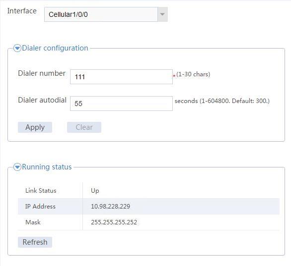
2. Configure 4G settings.
# On the top navigation bar, click Network.
# From the navigation pane, select Interface Configuration > 4G.
# On the page that opens, configure the following parameters:
¡ Select a supported cellular interface.
The device automatically creates Eth-channel interface 0 for the cellular interface, adds the Eth-channel interface to dialer group 1, and permits all IPv4 packets on the interface. By default, the Eth-channel interface uses DHCP to obtain an IP address and is enabled with traditional DDR.
¡ Configure the dial number for placing calls. The device will automatically enable automatic dialup.
¡ Set the interval for dialer autodial. DDR makes call attempts at the intervals until a connection is established.
# Click Apply.
3. Add the Eth-channel interface to the Untrust security zone.
# On the top navigation bar, click Network.
# From the navigation pane, select Security Zones.
# Add Eth-channel interface 0 to the Untrust security zone.
4. Create a security policy.
# On the top navigation bar, click Policies.
# From the navigation pane, select Security Policies > Security Policies.
# Click Create.
# In the dialog box that opens, create a security policy as follows:
¡ Specify the policy name as test-a.
¡ Select Trust as the source security zone.
¡ Select Untrust as the destination security zone.
¡ Select IPv4 as the type.
¡ Select Permit as the action.
¡ Specify 10.1.1.2/24 as the source IPv4 address.
¡ Retain the default settings for the other fields.
# Click OK.
5. Configure NAT outbound on the Eth-channel interface.
# On the top navigation bar, click Policies.
# From the navigation pane, select Interface NAT > IPv4 > Dynamic NAT.
# Click Create.
# In the dialog box that appears, configure outbound dynamic NAT:
¡ Select the Eth-channel interface.
¡ Select the IP address of the interface as the source address after NAT.
¡ Retain the default settings for the other fields.
# Click OK.
Verifying the configuration
Verify that the PC can access the LTE network through the device and you can view the operating status of the device from the Web interface.
To view the operating status of the device, click Network on the top navigation bar and then select Interface Configuration > 4G from the navigation pane.
Figure 2 Viewing device operating status