- Table of Contents
-
- 09-Configuration Examples
- 01-Web Login Configuration Examples
- 02-Internet Access Through a Static IP Address Configuration Examples
- 03-Internet access through PPPoE configuration examples
- 04-License Configuration Examples
- 05-Signature Library Upgrade Configuration Examples
- 06-Software Upgrade Examples
- 06-Software Upgrade Examples (only for F50X0-D and F5000-AK5X5 firewalls)
- 07-Routing deployment configuration examples
- 08-Transparent deployment configuration examples
- 09-Static routing configuration examples
- 10-RIP configuration examples
- 11-OSPF configuration examples
- 12-BGP configuration examples
- 13-Policy-based routing configuration examples
- 14-Security Policy Configuration Examples
- 15-APR-Based Security Policy Configuration Examples
- 16-Object Group Configuration Examples
- 17-User identification configuration examples
- 18-Attack defense configuration examples
- 19-IPCAR Configuration Examples
- 20-IPS Configuration Examples
- 21-URL Filtering Configuration Examples
- 22-Anti-Virus Configuration Examples
- 23-File Filtering Configuration Examples
- 24-Data Filtering Configuration Examples
- 25-WAF Configuration Examples
- 26-IP Reputation Configuration Examples
- 27-APT Defense Configuration Examples
- 28-NetShare Control Configuration Examples
- 29-Bandwidth Management Configuration Examples
- 30-IPsec configuration examples
- 31-SSL VPN IP access configuration examples
- 31-SSL VPN TCP access configuration examples
- 31-SSL VPN Web access configuration examples
- 32-L2TP Configuration Examples
- 33-NAT configuration examples
- 34-NPTv6 Configuration Examples
- 35-Policy-based NAT configuration examples
- 36-NAT hairpin configuration examples
- 37-NAT Flow Logging Configuration Examples
- 38-Inbound Link Load Balancing Configuration Examples
- 39-Outbound Link Load Balancing Configuration Examples
- 40-Server Load Balancing Configuration Examples
- 41-Transparent DNS Proxy Configuration Examples
- 42-High Availability Group Configuration Examples
- 43-Context Configuration Examples
- 43-Context Configuration Examples(only for F50X0-D and F5000-AK5X5 firewalls)
- 44-IRF configuration examples
- 44-IRF configuration examples(only for F50X0-D and F5000-AK5X5 firewalls)
- 45-DHCP configuration examples
- 46-DNS configuration examples
- 47-Server Connection Detection Configuration Examples
- 48-Connection Limit Configuration Examples
- 49-Public key management configuration examples
- 50-SSL Decryption Configuration Examples
- 51-MAC Address Learning Through a Layer 3 Device Configuration Examples
- 52-4G Configuration Examples
- 53-WLAN Configuration Examples
- Related Documents
-
| Title | Size | Download |
|---|---|---|
| 08-Transparent deployment configuration examples | 78.20 KB |
Transparent deployment configuration examples
· Example: Configuring transparent deployment
Transparent deployment enables the device to operate at Layer 2 (both the uplink and downlink service interfaces of the device operate at Layer 2) in the network, implementing security inspection and control for network traffic.
Transparent deployment can implement fast device deployment and security service onboarding without changing the existing network address plan.
This document is not restricted to specific software or hardware versions. Procedures and information in the examples might be slightly different depending on the software or hardware version of the device.
The configuration examples were created and verified in a lab environment, and all the devices were started with the factory default configuration. When you are working on a live network, make sure you understand the potential impact of every command on your network.
The following information is provided based on the assumption that you have basic knowledge of interface configuration, VLAN, and security policies.
Example: Configuring transparent deployment
Network configuration
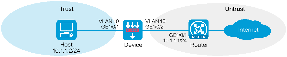
As shown in Figure 1, an enterprise deploys a device as a security protection device at the network border. The device can connect the internal network and the Internet and perform security inspection and control for network traffic without requiring changing the existing network configuration.
Software versions used
This configuration example was created and verified on R8860 of the F1000-AI-55 device.
Procedure
Configuring the router
# Configure the IPv4 address of GigabitEthernet 1/0/1 as 10.1.1.1/24.
# Configure a route, setting the next hop IPv4 address for traffic destined to the Internet as the IPv4 address of the peer end of the output interface.
Configuring the device
1. Create VLAN 10.
# On the top navigation bar, click Network.
# From the navigation pane, select Link > VLANs.
# Click Create.
# In the dialog box that opens, enter 10 for the VLAN list field, as shown in Figure 2.
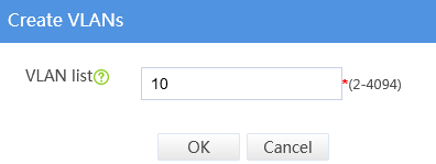
# Click OK.
2. Specify the link mode, security zone, and VLAN settings for interfaces.
# On the top navigation bar, click Network.
# From the navigation pane, select Interface Configuration > Interfaces.
# Click the Edit icon for GE 1/0/1.
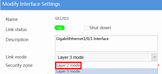
# In the dialog box that opens, set the link mode for the interface to Layer 2 mode, as shown in Figure 3.
Figure 3 Setting the Layer 2 link mode
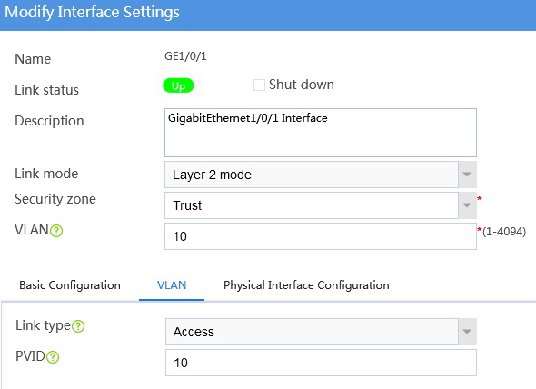
# Add GE 1/0/1 to the security zone Trust and VLAN 10, as shown in Figure 4.
Figure 4 Specifying the security zone and VLAN for the interface
# Use default settings for other parameters, and click OK.
# Specify the link mode (Layer 2 mode), security zone (Untrust), and VLAN (VLAN 10) settings for GE 1/0/2 in the same way GE 1/0/1 is configured. (Details not shown.)
3. Create a security policy to enable the host to access the external network.
# On the top navigation bar, click Policies.
# From the navigation pane, select Security Policies > Security Policies.
# Select Create > Create a policy.
# In the dialog box that opens, configure the security policy as shown in Figure 5.
Figure 5 Creating a security policy
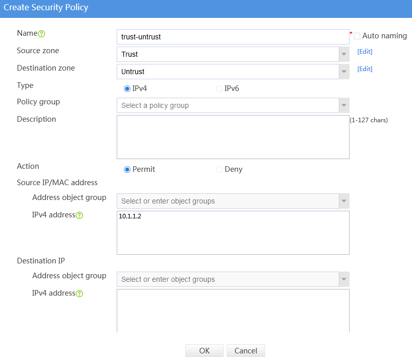
# Use default settings for other parameters, and then click OK.
Configuring the host
# Configure the IPv4 address of the default gateway as 10.1.1.1 for the host.
Verifying the configuration
# Verify that only the host with IP address 10.1.1.2 in the internal network can access the external network. Other hosts cannot access the external network.