- Table of Contents
-
- 09-Configuration Examples
- 01-Web Login Configuration Examples
- 02-Internet Access Through a Static IP Address Configuration Examples
- 03-Internet access through PPPoE configuration examples
- 04-License Configuration Examples
- 05-Signature Library Upgrade Configuration Examples
- 06-Software Upgrade Examples
- 06-Software Upgrade Examples (only for F50X0-D and F5000-AK5X5 firewalls)
- 07-Routing deployment configuration examples
- 08-Transparent deployment configuration examples
- 09-Static routing configuration examples
- 10-RIP configuration examples
- 11-OSPF configuration examples
- 12-BGP configuration examples
- 13-Policy-based routing configuration examples
- 14-Security Policy Configuration Examples
- 15-APR-Based Security Policy Configuration Examples
- 16-Object Group Configuration Examples
- 17-User identification configuration examples
- 18-Attack defense configuration examples
- 19-IPCAR Configuration Examples
- 20-IPS Configuration Examples
- 21-URL Filtering Configuration Examples
- 22-Anti-Virus Configuration Examples
- 23-File Filtering Configuration Examples
- 24-Data Filtering Configuration Examples
- 25-WAF Configuration Examples
- 26-IP Reputation Configuration Examples
- 27-APT Defense Configuration Examples
- 28-NetShare Control Configuration Examples
- 29-Bandwidth Management Configuration Examples
- 30-IPsec configuration examples
- 31-SSL VPN IP access configuration examples
- 31-SSL VPN TCP access configuration examples
- 31-SSL VPN Web access configuration examples
- 32-L2TP Configuration Examples
- 33-NAT configuration examples
- 34-NPTv6 Configuration Examples
- 35-Policy-based NAT configuration examples
- 36-NAT hairpin configuration examples
- 37-NAT Flow Logging Configuration Examples
- 38-Inbound Link Load Balancing Configuration Examples
- 39-Outbound Link Load Balancing Configuration Examples
- 40-Server Load Balancing Configuration Examples
- 41-Transparent DNS Proxy Configuration Examples
- 42-High Availability Group Configuration Examples
- 43-Context Configuration Examples
- 43-Context Configuration Examples(only for F50X0-D and F5000-AK5X5 firewalls)
- 44-IRF configuration examples
- 44-IRF configuration examples(only for F50X0-D and F5000-AK5X5 firewalls)
- 45-DHCP configuration examples
- 46-DNS configuration examples
- 47-Server Connection Detection Configuration Examples
- 48-Connection Limit Configuration Examples
- 49-Public key management configuration examples
- 50-SSL Decryption Configuration Examples
- 51-MAC Address Learning Through a Layer 3 Device Configuration Examples
- 52-4G Configuration Examples
- 53-WLAN Configuration Examples
- Related Documents
-
| Title | Size | Download |
|---|---|---|
| 32-L2TP Configuration Examples | 316.49 KB |
Contents
The following information provides L2TP configuration examples.
This document is not restricted to specific software or hardware versions. Procedures and information in the examples might be slightly different depending on the software or hardware version of the device.
The configuration examples were created and verified in a lab environment, and all the devices were started with the factory default configuration. When you are working on a live network, make sure you understand the potential impact of every command on your network.
The following information is provided based on the assumption that you have basic knowledge of L2TP.
Network configuration
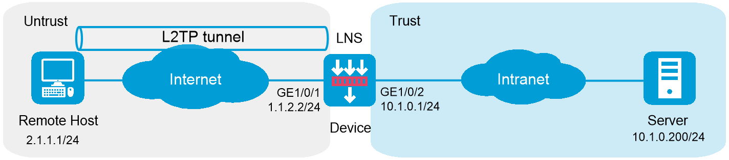
As shown in Figure 1, a PPP user directly establishes an L2TP tunnel to an LNS, and accesses the HQ of the company through the L2TP tunnel.
Configure the network to meet the following requirements:
· An enterprise branch can access the intranet resources of the company through an L2TP VPN.
· Traveling employees can access the intranet to work remotely through an L2TP VPN.
Software version used
This configuration example was created and verified on R8860 of the F1000-AI-55 device.
Procedure
Configuring Device
1. Assign IP addresses to interfaces and add the interfaces to security zones.
# On the top navigation bar, click Network.
# From the navigation pane, select Interface Configuration > Interfaces.
# Click the Edit icon for GE 1/0/1. In the dialog box that opens, configure the interface:
¡ Select the Untrust security zone.
¡ On the IPv4 Address tab, enter the IP address and mask of the interface. In this example, enter 1.1.2.2/24.
¡ Use the default settings for other parameters.
# Click OK.
# Click the Edit icon for GE 1/0/2. In the dialog box that opens, configure the interface:
¡ Select the Trust security zone.
¡ On the IPv4 Address tab, enter the IP address and mask of the interface. In this example, enter 10.1.0.1/24.
¡ Use the default settings for other parameters.
# Click OK.
# On the top navigation bar, click Network.
# From the navigation pane, select VPN > L2TP.
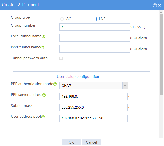
# Click Create. In the dialog box that opens, configure parameters as shown in the following figure:
Figure 2 Configuring L2TP
# On the top navigation bar, click Network.
# From the navigation pane, select Security Zones.
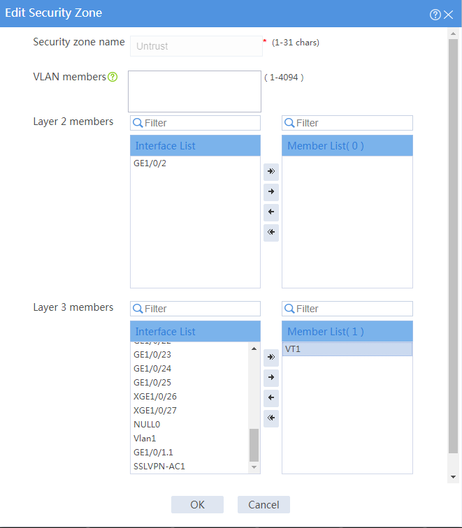
# Click the Edit icon for security zone Untrust to enter the page for editing the security zone.
# On this page, configure parameters as shown in the following figure:
Figure 3 Editing a security zone
2. Configure routing.
This section takes static routing as an example. If you need dynamic routing in your network, configure the corresponding dynamic routing protocol as needed.
# On the top navigation bar, click Network.
# From the navigation pane, select Routing > Static Routing.
# On the IPv4 Static Routing tab, click Create.
# In the dialog box that opens, configure an IPv4 static route as follows:
¡ Enter destination address 2.1.1.1.
¡ Enter mask length 24.
¡ Enter next hop address 1.1.2.3.
¡ Use the default settings for other parameters.
# Click OK.
3. Configure security policies.
# On the top navigation bar, click Policies.
# From the navigation pane, select Security Policies > Security Policies. Click Create.
# In the dialog box that opens, create a security policy and configure it as follows:
¡ Enter security policy name untrust-local.
¡ Select source security zone Untrust.
¡ Select destination security zone Local.
¡ Set the type to IPv4.
¡ Set the action to Permit.
¡ Select service l2tp.
¡ Use the default settings for other parameters.
# Repeat the steps above to create a new security policy with the fowling parameter settings:
¡ Enter security policy name untrust-trust.
¡ Select source security zone Untrust.
¡ Select destination security zone Trust.
¡ Set the type to IPv4.
¡ Set the action to Permit.
¡ Enter source IPv4 addresses 192.168.0.10-192.168.0.20.
¡ Enter destination IPv4 address 10.1.0.200.
¡ Use the default settings for other parameters.
# Click OK.
4. Create an L2TP user.
# On the top navigation bar, click Objects.
# From the navigation pane, select User > User Management > Local Users.
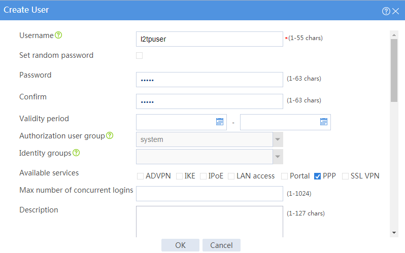
# Click Create. Create an L2TP user. Set the username to l2tpuser, set the password to hello, and select service type PPP, as shown in the following figure:
Figure 4 Creating an L2TP user
5. Enable L2TP.
# On the top navigation bar, click Network.
# From the navigation pane, select VPN > L2TP.
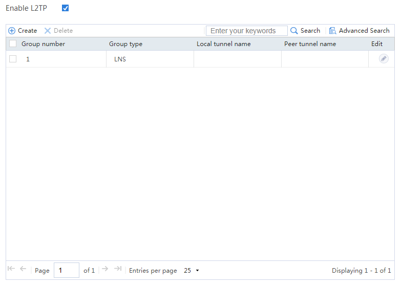
# Click the L2TP tab. On this tab, enable L2TP.
Figure 5 Enabling L2TP
Configuring a VPN client
# Click the Network icon in the lower right corner of your PC, and click Open Network and Sharing Center page.
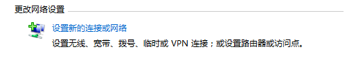
# Access the Change your networking settings area.
Figure 6 Changing your networking settings
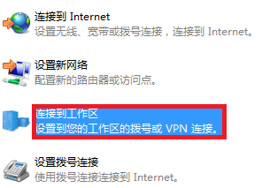
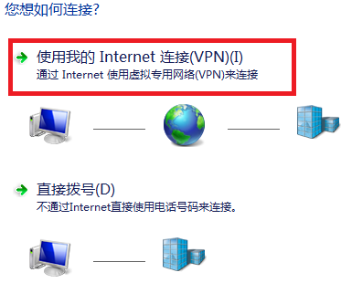
# Click Connect to a workplace, and select Use my Internet connection (VPN), as shown in the following figures.
Figure 7 Setting VPN
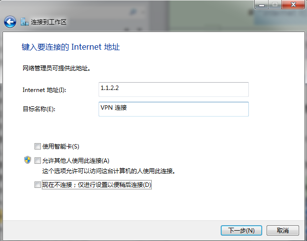
# Click Don’t connect now; just set it up so I can connect later. In the Internet address field, enter the IP address of the interface connecting the device to the Internet.
Figure 8 Setting the IP address
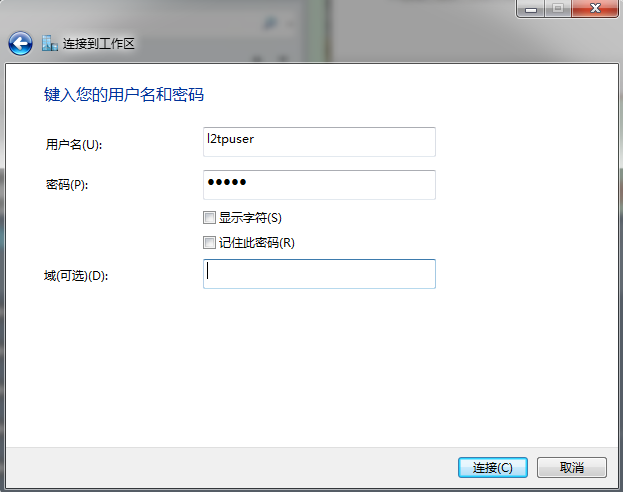
# Set the username and password for VPN dialup, as shown in the following figure:
Figure 9 Setting the username and password
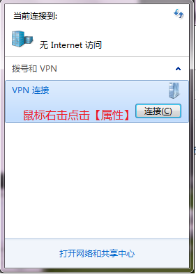
# Set the Network icon in the lower right corner of your PC.
# Right-click the new VPN connection, and select Properties from the shortcut menu.
Figure 10 Setting a VPN connection
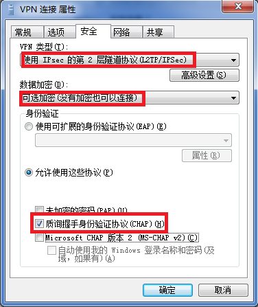
# On the Security tab, configure the VPN connection as follows:
· Select Layer 2 Tunneling Protocol with IPsec (L2TP/IPsec) from the Type of VPN list.
· Select Optional encryption (connect even if no encryption) from the Data encryption list.
· Select Challenge Handshake Authentication Protocol (CHAP) in the Allow these protocols area.
Figure 11 Setting the VPN properties
Verifying the configuration
# After a user successfully dials up, you can see the L2TP tunnel information, as shown in the following figure:
Figure 12 L2TP tunnel information
![]()