- Table of Contents
-
- 09-Configuration Examples
- 01-Web Login Configuration Examples
- 02-Internet Access Through a Static IP Address Configuration Examples
- 03-Internet access through PPPoE configuration examples
- 04-License Configuration Examples
- 05-Signature Library Upgrade Configuration Examples
- 06-Software Upgrade Examples
- 06-Software Upgrade Examples (only for F50X0-D and F5000-AK5X5 firewalls)
- 07-Routing deployment configuration examples
- 08-Transparent deployment configuration examples
- 09-Static routing configuration examples
- 10-RIP configuration examples
- 11-OSPF configuration examples
- 12-BGP configuration examples
- 13-Policy-based routing configuration examples
- 14-Security Policy Configuration Examples
- 15-APR-Based Security Policy Configuration Examples
- 16-Object Group Configuration Examples
- 17-User identification configuration examples
- 18-Attack defense configuration examples
- 19-IPCAR Configuration Examples
- 20-IPS Configuration Examples
- 21-URL Filtering Configuration Examples
- 22-Anti-Virus Configuration Examples
- 23-File Filtering Configuration Examples
- 24-Data Filtering Configuration Examples
- 25-WAF Configuration Examples
- 26-IP Reputation Configuration Examples
- 27-APT Defense Configuration Examples
- 28-NetShare Control Configuration Examples
- 29-Bandwidth Management Configuration Examples
- 30-IPsec configuration examples
- 31-SSL VPN IP access configuration examples
- 31-SSL VPN TCP access configuration examples
- 31-SSL VPN Web access configuration examples
- 32-L2TP Configuration Examples
- 33-NAT configuration examples
- 34-NPTv6 Configuration Examples
- 35-Policy-based NAT configuration examples
- 36-NAT hairpin configuration examples
- 37-NAT Flow Logging Configuration Examples
- 38-Inbound Link Load Balancing Configuration Examples
- 39-Outbound Link Load Balancing Configuration Examples
- 40-Server Load Balancing Configuration Examples
- 41-Transparent DNS Proxy Configuration Examples
- 42-High Availability Group Configuration Examples
- 43-Context Configuration Examples
- 43-Context Configuration Examples(only for F50X0-D and F5000-AK5X5 firewalls)
- 44-IRF configuration examples
- 44-IRF configuration examples(only for F50X0-D and F5000-AK5X5 firewalls)
- 45-DHCP configuration examples
- 46-DNS configuration examples
- 47-Server Connection Detection Configuration Examples
- 48-Connection Limit Configuration Examples
- 49-Public key management configuration examples
- 50-SSL Decryption Configuration Examples
- 51-MAC Address Learning Through a Layer 3 Device Configuration Examples
- 52-4G Configuration Examples
- 53-WLAN Configuration Examples
- Related Documents
-
| Title | Size | Download |
|---|---|---|
| 31-SSL VPN Web access configuration examples | 1.00 MB |
SSL VPN Web access configuration examples
· Example: Configuring Web access with mutual certificate authentication
· Example: Configuring Web access with a self-signed server certificate
The following information provides SSL VPN Web access configuration examples.
This document is not restricted to specific software or hardware versions. Procedure and information in the examples might be slightly different depending on the software or hardware version of the device.
The configuration examples were created and verified in a lab environment, and all the devices were started with the factory default configuration. When you are working on a live network, make sure you understand the potential impact of every command on your network.
The following information is provided based on the assumption that you have basic knowledge of SSL VPN.
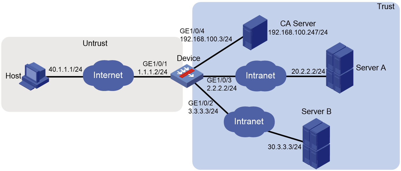
Network configuration
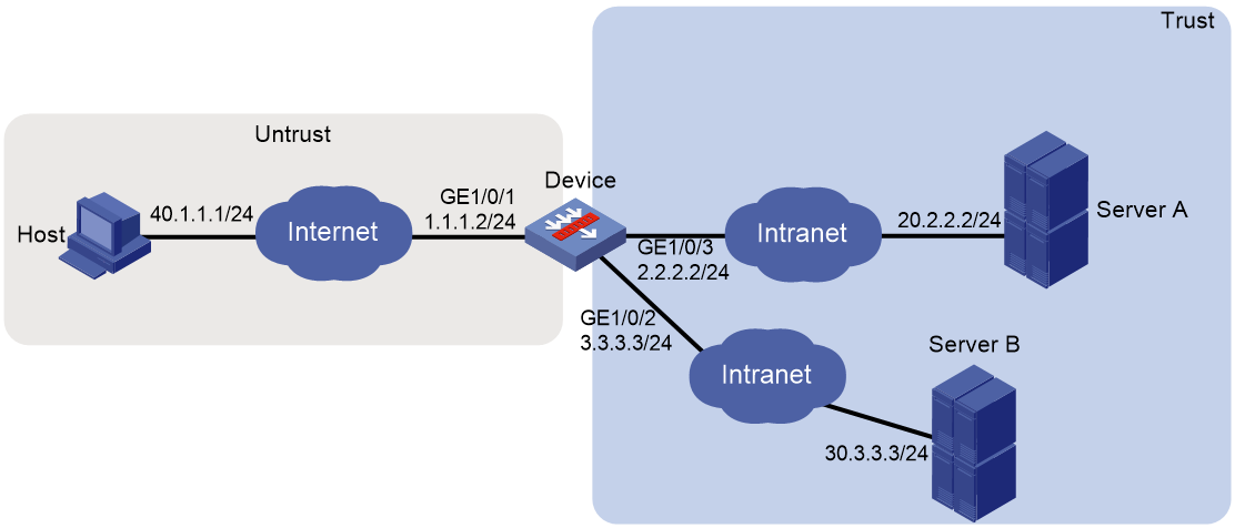
As shown in Figure 1, the device acts as the SSL VPN gateway that connects the public network and the private network. A Windows Server 2008 R2 CA server is deployed on the private network. Users need to access resources on internal Web servers Server A and Server B. Both Web servers use HTTP over port 80.
Configure the SSL VPN Web access service on the device to allow users to access Server A and Server B in Web access mode.
Configure the device to perform local authentication and authorization for Web access users. Require users to pass both password and certificate authentication for Web access. To enhance security, request an SSL server certificate for the device from the CA server rather than use the default certificate.
Software versions used
This configuration example was created and verified on R8860 of the F1000-AI-55 device.
Procedure
Configuring the device
1. Assign IP addresses to interfaces and add the interfaces to security zones.
# On the top navigation bar, click the Network tab.
# From the navigation pane, select Interface Configuration > Interfaces.
# Click the Edit icon for GE 1/0/1.
# In the dialog box that opens, configure the interface:
a. Select the Untrust security zone.
b. On the IPv4 Address tab, enter the IP address and mask of the interface. In this example, enter 1.1.1.2/24.
c. Use the default settings for other parameters.
d. Click OK.
# Add GE 1/0/2 to the Trust security zone and set its IP address to 3.3.3.3/24 in the same way you configure GE 1/0/1.
# Add GE 1/0/3 to the Trust security zone and set its IP address to 2.2.2.2/24 in the same way you configure GE 1/0/1.
# Add GE 1/0/4 to the Trust security zone and set its IP address to 192.168.100.3/24 in the same way you configure GE 1/0/1.
2. Configure settings for routing:
This example configures static routes.
# On the top navigation bar, click Network.
# From the navigation pane, select Routing > Static Routing.
# On the IPv4 Static Routing tab, click Create.
# In the dialog box that opens, configure a static IPv4 route to reach 40.1.1.1:
a. Enter destination IP address 40.1.1.1.
b. Enter mask length 24.
c. Enter next hop address 1.1.1.3.
d. Use the default settings for other parameters.
e. Click OK.
# Configure a static IPv4 route to reach 20.2.2.2:
a. Enter destination IP address 20.2.2.2.
b. Enter mask length 24.
c. Enter next hop address 2.2.2.3.
d. Use the default settings for other parameters.
e. Click OK.
# Configure a static IPv4 route to reach 30.3.3.3:
a. Enter destination IP address 30.3.3.3.
b. Enter mask length 24.
c. Enter next hop address 3.3.3.4.
d. Use the default settings for other parameters.
e. Click OK.
3. Create security policies:
# On the top navigation bar, click Policies.
# From the navigation pane, select Security Policies > Security Policies.
# Click Create, and then click Create a policy.
# In the dialog box that opens, configure a security policy named untrust-local to permit the specified traffic from the Untrust to Local security zones:
¡ Enter policy name untrust-local.
¡ Select source zone Untrust.
¡ Select destination zone Local.
¡ Select type IPv4.
¡ Select action Permit.
¡ Select source IPv4 address 40.1.1.1.
¡ Select destination IPv4 address 1.1.1.2.
¡ Use the default settings for other parameters.
# Click OK.
# Create security policy local-trust to permit the specified traffic from the Local to Trust security zones:
¡ Enter policy name local-trust.
¡ Select source zone Local.
¡ Select destination zone Trust.
¡ Select type IPv4.
¡ Select action Permit.
¡ Select source IPv4 addresses 2.2.2.2, 3.3.3.3, and 192.168.100.3.
¡ Select destination IPv4 addresses 20.2.2.2, 30.3.3.3, and 192.168.100.247.
¡ Use the default settings for other parameters.
# Click OK.
4. Request a server certificate for the device:
a. Create a certificate subject:
# On the top navigation bar, click Objects.
# From the navigation pane, select PKI > Certificate Subject.
# Click Create.
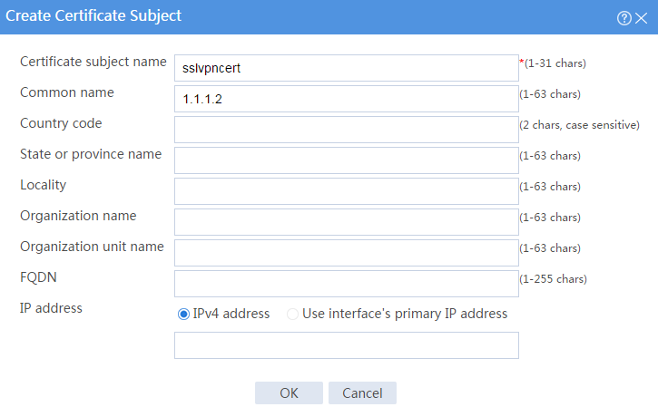
# Create a certificate subject as shown in Figure 2, and the click OK.
Figure 2 Creating a certificate subject
b. Create a PKI domain:
# On the Certificate page, click Create PKI domain.
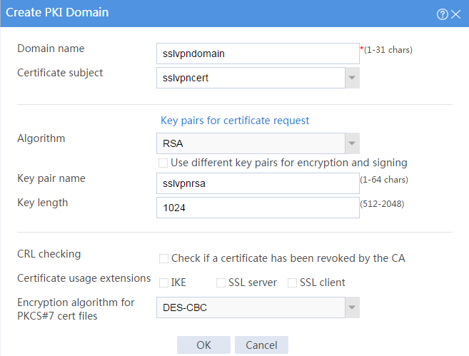
# Create a PKI domain as shown in Figure 3, and then click OK.
Figure 3 Creating a PKI domain
c. Create a certificate request:
# On the Certificate page, click Submit Cert Request.
# Configure the certificate request settings as shown in Figure 4.
Figure 4 Creating a certificate request
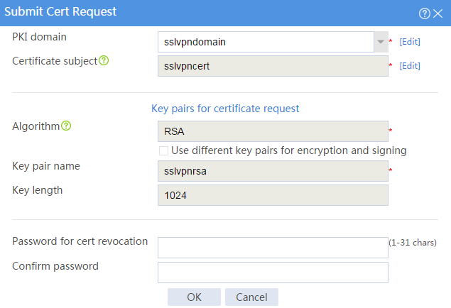
# Click OK.
The certificate request content will be displayed, as shown in Figure 5.
Figure 5 Certificate request content
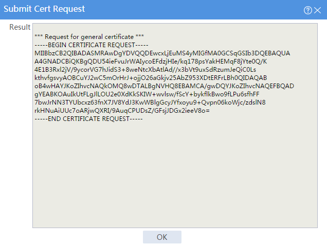
# Copy the certificate request content and click OK.
d. Request a server certificate from the CA:
# Enter http://192.168.100.247/certsrv in the browser address bar.
# On the certificate service home page shown in Figure 6, click Request a certificate.
Figure 6 Certificate service home page

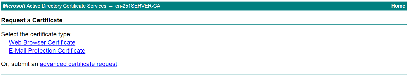
# On the Request a Certificate page shown in Figure 7, click advanced certificate request.
Figure 7 Request a Certificate page
# Paste the previously copied certificate request content in the Base-64-encoded certificate request CMC or PKCS # 10 or PKCS # 7) field, as shown in Figure 8.
Figure 8 Pasting the certificate request content
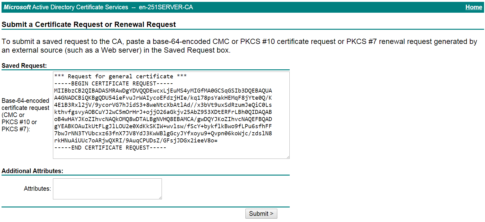
# Click Submit.
After the certificate request is approved by the CA administrator, enter http://192.168.100.247/certsrv in the browser address bar.
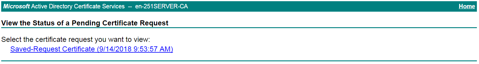
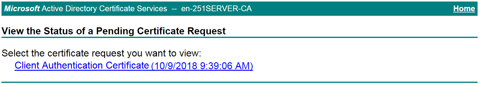
# On the certificate service home page shown in Figure 9, click View the status of a pending certificate request.
Figure 9 Certificate service home page

# Select the certificate request you want to view.
Figure 10 View the Status of a Pending Certificate Request page
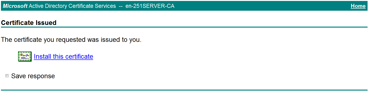
The Certificate Issued page opens, indicating that the requested server certificate has been issued, as shown in Figure 11.
Figure 11 Certificate Issued page
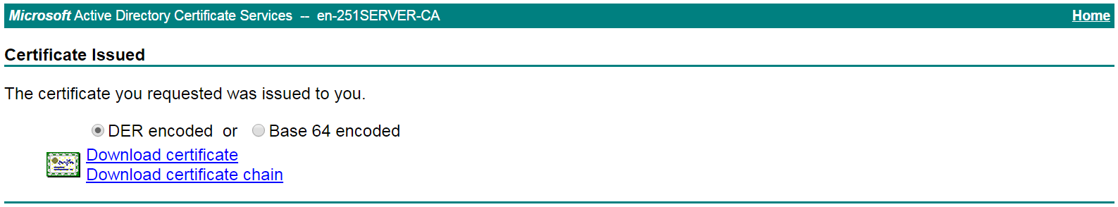
# Click Download certificate to download the server certificate and save it locally.
5. Download the CA certificate:
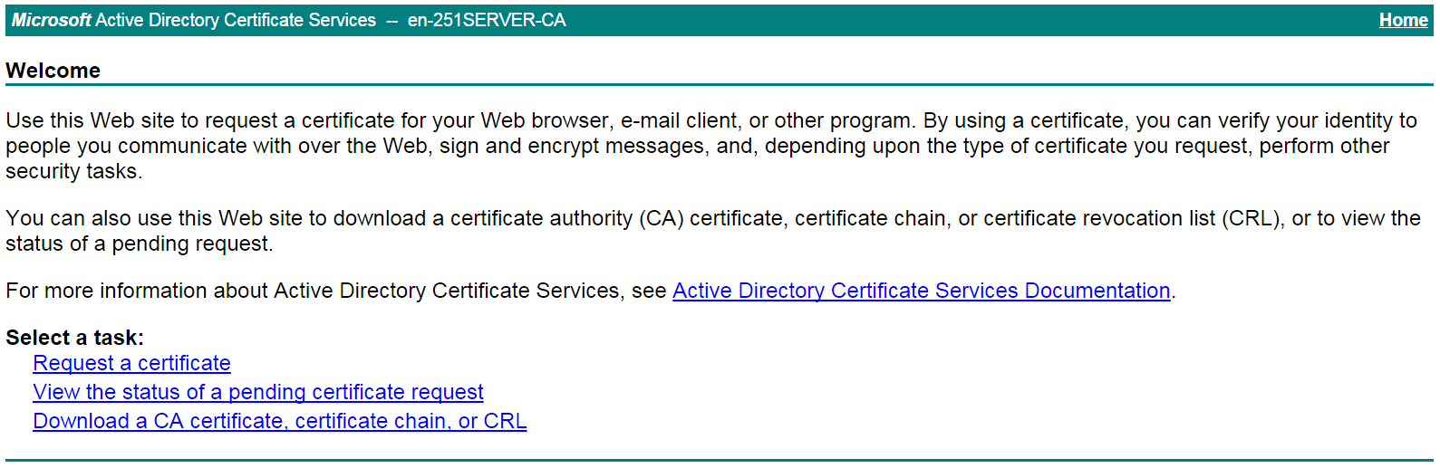
# Enter http://192.168.100.247/certsrv in the browser address bar.
# On the certificate service home page shown in Figure 12, click Download a CA certificate, certificate chain, or CRL.
Figure 12 Certificate service home page
# On the Download a CA certificate, certificate chain, or CRL page shown in Figure 13, click Download CA certificate.
Figure 13 Download a CA certificate, certificate chain, or CRL page

# Save the downloaded CA certificate locally.
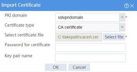
6. Import the CA certificate and server certificate to the PKI domain:
a. Import the CA certificate:
# On the top navigation bar, click Objects.
# From the navigation pane, select PKI > Certificate.
# Click Import certificate.
# Import the locally saved CA certificate, as shown in Figure 14, and then click OK.
Figure 14 Importing the CA certificate
b. Import the server certificate:
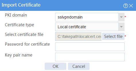
# On the Certificate page, click Import certificate.
# Import the locally saved server certificate, as shown in Figure 15, and then click OK.
Figure 15 Importing the server certificate
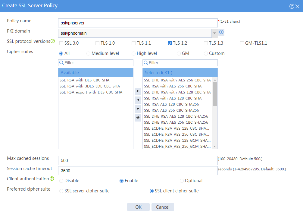
7. Configure an SSL server policy:
# On the top navigation bar, click Objects.
# From the navigation pane, select SSL > SSL Server Policies.
# Click Create.
# Configure an SSL server policy as shown in Figure 16, and then click OK.
Figure 16 Creating an SSL server policy
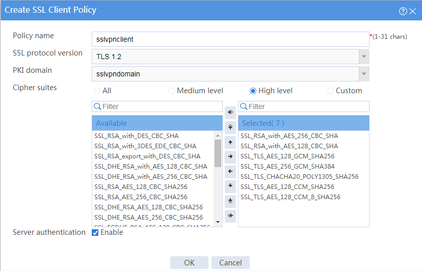
8. Configure an SSL client policy:
# On the top navigation bar, click Objects.
# From the navigation pane, select SSL > SSL Client Policies.
# Click Create.
# Configure an SSL client policy as shown in Figure 17, and then click OK.
Figure 17 Creating an SSL client policy
9. Configure the SSL VPN gateway:
# On the top navigation bar, click Network.
# From the navigation pane, select SSL VPN > SSL VPN Gateways.
# Click Create.
# Create an SSL VPN gateway as shown in Figure 18, and then click OK.
Figure 18 Creating an SSL VPN gateway

10. Configure an SSL VPN context:
# On the top navigation bar, click Network.
# From the navigation pane, select SSL VPN > SSL VPN Contexts.
# Click Create.
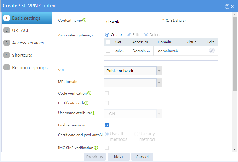
# Configure the basic settings for the SSL VPN context as shown in Figure 42, and then click Next.
Figure 19 Configuring basic settings for an SSL VPN context

# On the URI ACL page, click Next.
# On the Access services page, select Web access and click Next.
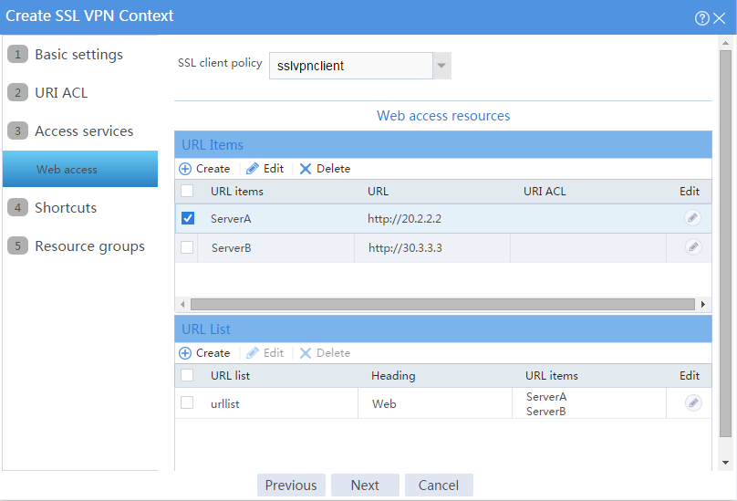
# On the Web access page, configure the Web access service as follows:
a. Select sslvpnclient from the SSL client policy list.
b. Configure two URL items pointing to Server A and Server B, respectively.
c. Add the two URL items to URL list urllist.
d. Click Next.
Figure 20 Configuring the Web access service
# Click Next on the Shortcuts page.
# On the Resource groups page, click Create.
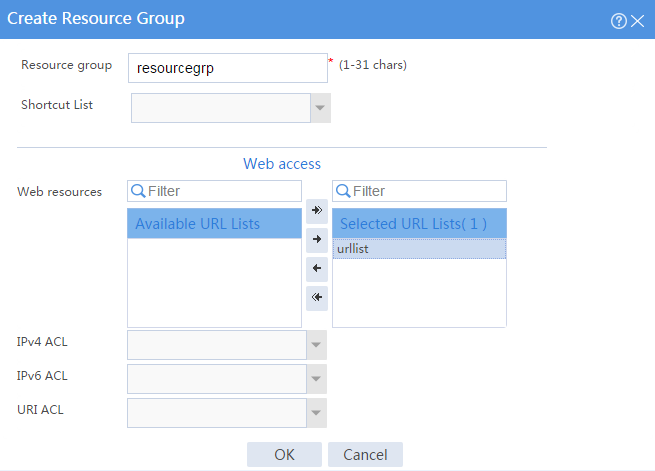
# Create a resource group named resourcegrp and select URL list urllist as the accessible Web resources, as shown in Figure 21.
# Click OK.
Figure 21 Creating an SSL VPN resource group

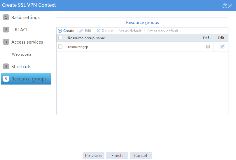
The newly created resource group is displayed on the Resource groups page, as shown in Figure 22.
Figure 22 Resource groups configuration page
# Click Finish.
# Select the Enable check box to enable the SSL VPN context, as shown in Figure 23.
Figure 23 Enabling the SSL VPN context
![]()
11. Create an SSL VPN user:
# On the top navigation bar, click Objects.
# From the navigation pane, select User > User Management > Local Users.
# Click Create.
# Create an SSL VPN user:
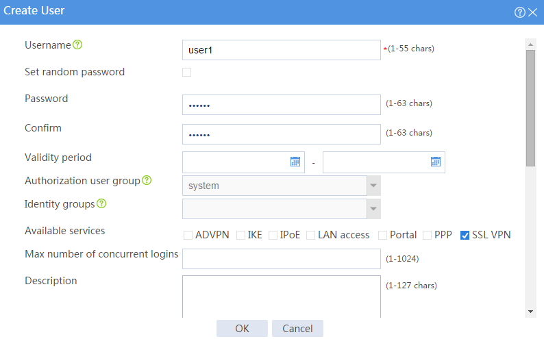
a. Set the username to user1 and password to 123456, and select SSL VPN as the available service, as shown in Figure 24.
Figure 24 Creating an SSL VPN user
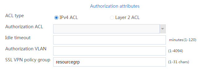
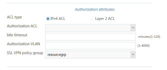
b. In the Authorization Attributes area, authorize the user to use SSL VPN resource group resourcegrp, as shown in Figure 25.
Figure 25 Setting the authorization attributes for the SSL VPN user
c. Click OK.
Configuring the host
1. Configure the IP address and gateway address settings for the host and make sure it can reach the SSL VPN gateway and the CA server.
2. Submit a client certificate request to the CA server:
a. Enter http://192.168.100.247/certsrv in the browser address bar.
b. On the certificate service home page shown in Figure 26, click Request a certificate.
Figure 26 Certificate service home page

c. On the Request a Certificate page shown in Figure 27, click advanced certificate request.
Figure 27 Request a Certificate page

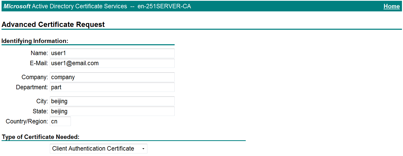
d. Create a client certificate request, as shown in Figure 28.
Figure 28 Creating a client certificate request
e. Click Submit.
3. Install the client certificate on the host:
a. After the certificate request is approved by the CA administrator, enter http://192.168.100.247/certsrv in the browser address bar.
b. On the certificate service home page shown in Figure 29, click View the status of a pending certificate request.
Figure 29 Certificate service home page

The View the Status of a Pending Certificate Request page opens, as shown in Figure 30.
Figure 30 View the Status of a Pending Certificate Request page
c. Click the client certificate whose status you want to view.
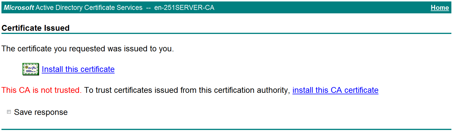
d. On the Certificate Issued page shown in Figure 31, click Install this certificate to install the client certificate.
Figure 31 Installing the client certificate
If the host does not have a CA certificate, the page shown in Figure 32 opens. You must install the CA certificate first.
e. Click install this CA certificate to install the CA certificate. Then, click Install this certificate to install the client certificate.
Figure 32 Installing the CA certificate and then the client certificate
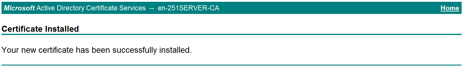
After the client certificate is installed, the Certificate Installed page shown in Figure 33 opens.
Figure 33 Certificate Installed page
Verifying the configuration
1. In the browser address bar of the host, enter https://1.1.1.2 and press Enter.
2. On the Select a certificate page, select the client certificate for authentication, as shown in Figure 34.
Figure 34 Select a certificate page
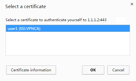
3. Click OK.
4. On the Domain List page shown in Figure 35, click domainweb.
5. On the SSL VPN login page shown in Figure 36, enter username user1 and password and 123456, and then click Login
The SSL VPN home page opens, displaying the Web resources the user can access in the BookMark area, as shown in Figure 37.
Figure 37 Accessible Web resources
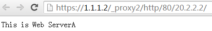
6. Click ServerA to access Web resources on Server A.
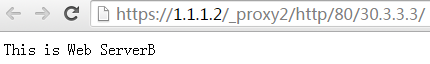
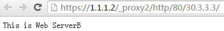
7. Click ServerB to access Web resources on Server B.
Figure 39 Accessing Server B
Network configuration
As shown in Figure 40, the device acts as the SSL VPN gateway that connects the public network and the private network. Users need to access resources on internal Web servers Server A and Server B. Both servers use HTTP over port 80.
Configure the SSL VPN Web access service on the device to allow users to access Server A and Server B in Web access mode.
Configure the device to perform local authentication and authorization for Web access users.
The device uses a self-signed SSL server certificate.
Software versions used
This configuration example was created and verified on R8860 of the F1000-AI-55 device.
Procedure
Configuring the device
1. Assign IP addresses to interfaces and add the interfaces to security zones:
# On the top navigation bar, click Network.
# From the navigation pane, select Interface Configuration > Interfaces.
# Click the Edit icon for GE 1/0/1.
# In the dialog box that opens, configure the interface:
a. Select the Untrust security zone.
b. On the IPv4 Address tab, enter the IP address and mask of the interface. In this example, enter 1.1.1.2/24.
c. Use the default settings for other parameters.
d. Click OK.
# Add GE 1/0/2 to the Trust security zone and set its IP address to 3.3.3.3/24 in the same way you configure GE 1/0/1.
# Add GE 1/0/3 to the Trust security zone and set its IP address to 2.2.2.2/24 in the same way you configure GE 1/0/1.
2. Configure settings for routing:
This example configures static routes.
# On the top navigation bar, click Network.
# From the navigation pane, select Routing > Static Routing.
# On the IPv4 Static Routing tab, click Create.
# In the dialog box that opens, configure a static IPv4 route to reach 20.2.2.2:
a. Enter destination IP address 20.2.2.2.
b. Enter mask length 24.
c. Enter next hop address 2.2.2.3.
d. Use the default settings for other parameters.
e. Click OK.
# Configure a static IPv4 route to reach 30.3.3.3:
a. Enter destination IP address 30.3.3.3.
b. Enter mask length 24.
c. Enter next hop address 3.3.3.4.
d. Use the default settings for other parameters.
e. Click OK.
# Configure a static IPv4 route to reach 40.1.1.1:
a. Enter destination IP address 40.1.1.1.
b. Enter mask length 24.
c. Enter next hop address 1.1.1.3.
d. Use the default settings for other parameters.
e. Click OK.
3. Create security policies:
# On the top navigation bar, click Policies.
# From the navigation pane, select Security Policies > Security Policies.
# Click Create, and then click Create a policy.
# In the dialog box that opens, configure a security policy named untrust-local to permit the specified traffic from the Untrust to Local security zones:
¡ Enter policy name untrust-local.
¡ Select source zone Untrust.
¡ Select destination zone Local.
¡ Select type IPv4.
¡ Select action Permit.
¡ Select source IPv4 address 40.1.1.1.
¡ Select destination IPv4 address 1.1.1.2.
¡ Use the default settings for other parameters.
# Click OK.
# Create security policy local-trust to permit the specified traffic from the Local to Trust security zones:
¡ Enter policy name local-trust.
¡ Select source zone Local.
¡ Select destination zone Trust.
¡ Select type IPv4.
¡ Select action Permit.
¡ Select source IPv4 addresses 2.2.2.2 and 3.3.3.3.
¡ Select destination IPv4 addresses 20.2.2.2, and 30.3.3.3.
¡ Use the default settings for other parameters.
# Click OK.
4. Configure the SSL VPN gateway:
# On the top navigation bar, click Network.
# From the navigation pane, select SSL VPN > SSL VPN Gateways.
# Click Create.
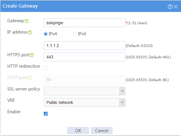
# Create an SSL VPN gateway as shown in Figure 41, and then click OK.
Figure 41 Creating an SSL VPN gateway
5. Configure an SSL VPN context:
# On the top navigation bar, click Network.
# From the navigation pane, select SSL VPN > SSL VPN Contexts.
# Click Create.
# Configure the basic settings for the SSL VPN context as shown in Figure 42, and then click Next.
Figure 42 Configuring basic settings for an SSL VPN context
# On the URI ACL page, click Next.
# On the Access services page, select Web access and click Next.
# On the Web access page, configure the Web access service as follows:
a. Configure two URL items pointing to Server A and Server B, respectively.
b. Add the two URL items to URL list urllist.
c. Click Next.
Figure 43 Configuring Web access service

# Click Next on the Shortcuts page.
# On the Resource groups page, click Create.
# Create a resource group named resourcegrp and select URL list urllist as the accessible Web resources, as shown in Figure 44.
Figure 44 Creating an SSL VPN resource group
# Click OK.
The newly created resource group is displayed on the Resource groups page, as shown in Figure 45.
Figure 45 Resource groups configuration page

# Click Finish.
# Select the Enable check box to enable the SSL VPN context, as shown in Figure 46.
Figure 46 Enabling the SSL VPN context
![]()
6. Create an SSL VPN user:
# On the top navigation bar, click Objects.
# From the navigation pane, select User > User Management > Local Users.
# Click Create.
# Create an SSL VPN user:
a. Set the username to user1 and password to 123456, and select SSL VPN as the available service, as shown in Figure 47.
Figure 47 Creating an SSL VPN user

b. In the Authorization Attributes area, authorize the user to use SSL VPN resource group resourcegrp, as shown in Figure 48.
Figure 48 Setting the authorization attributes for the SSL VPN user
c. Click OK.
Configuring the host
# Configure the IP address and gateway address settings for the host and make sure it can reach the SSL VPN gateway.
Verifying the configuration
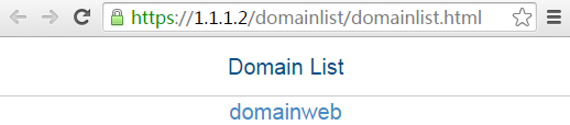
1. In the browser address bar of the host, enter https://1.1.1.2 and press Enter to open the domain list page.
Figure 49 Domain list page
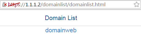
2. Select domainweb to access the login page.
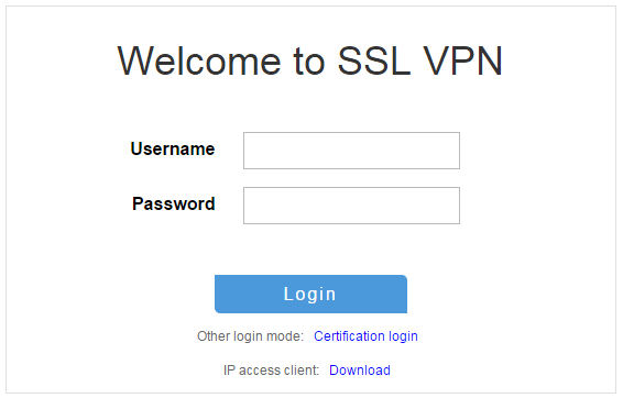
3. On the login page, enter username user1 and password 123456, and then click Login.
Figure 50 Login page

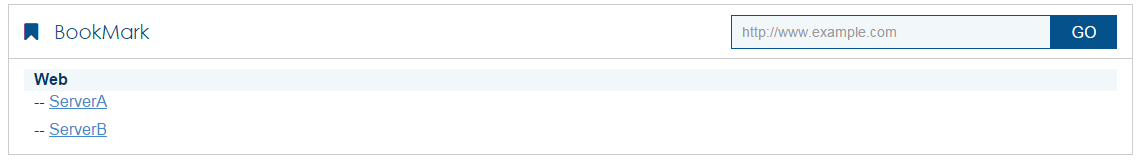
The SSL VPN home page opens, displaying the Web resources the user can access in the BookMark area.
Figure 51 Accessible Web resources

4. Click ServerA to access Web resources on Server A.
Figure 52 Accessing Server A
5. Click ServerB to access Web resources on Server B.
Figure 53 Accessing Server B