- Table of Contents
-
- 09-Configuration Examples
- 01-Web Login Configuration Examples
- 02-Internet Access Through a Static IP Address Configuration Examples
- 03-Internet access through PPPoE configuration examples
- 04-License Configuration Examples
- 05-Signature Library Upgrade Configuration Examples
- 06-Software Upgrade Examples
- 06-Software Upgrade Examples (only for F50X0-D and F5000-AK5X5 firewalls)
- 07-Routing deployment configuration examples
- 08-Transparent deployment configuration examples
- 09-Static routing configuration examples
- 10-RIP configuration examples
- 11-OSPF configuration examples
- 12-BGP configuration examples
- 13-Policy-based routing configuration examples
- 14-Security Policy Configuration Examples
- 15-APR-Based Security Policy Configuration Examples
- 16-Object Group Configuration Examples
- 17-User identification configuration examples
- 18-Attack defense configuration examples
- 19-IPCAR Configuration Examples
- 20-IPS Configuration Examples
- 21-URL Filtering Configuration Examples
- 22-Anti-Virus Configuration Examples
- 23-File Filtering Configuration Examples
- 24-Data Filtering Configuration Examples
- 25-WAF Configuration Examples
- 26-IP Reputation Configuration Examples
- 27-APT Defense Configuration Examples
- 28-NetShare Control Configuration Examples
- 29-Bandwidth Management Configuration Examples
- 30-IPsec configuration examples
- 31-SSL VPN IP access configuration examples
- 31-SSL VPN TCP access configuration examples
- 31-SSL VPN Web access configuration examples
- 32-L2TP Configuration Examples
- 33-NAT configuration examples
- 34-NPTv6 Configuration Examples
- 35-Policy-based NAT configuration examples
- 36-NAT hairpin configuration examples
- 37-NAT Flow Logging Configuration Examples
- 38-Inbound Link Load Balancing Configuration Examples
- 39-Outbound Link Load Balancing Configuration Examples
- 40-Server Load Balancing Configuration Examples
- 41-Transparent DNS Proxy Configuration Examples
- 42-High Availability Group Configuration Examples
- 43-Context Configuration Examples
- 43-Context Configuration Examples(only for F50X0-D and F5000-AK5X5 firewalls)
- 44-IRF configuration examples
- 44-IRF configuration examples(only for F50X0-D and F5000-AK5X5 firewalls)
- 45-DHCP configuration examples
- 46-DNS configuration examples
- 47-Server Connection Detection Configuration Examples
- 48-Connection Limit Configuration Examples
- 49-Public key management configuration examples
- 50-SSL Decryption Configuration Examples
- 51-MAC Address Learning Through a Layer 3 Device Configuration Examples
- 52-4G Configuration Examples
- 53-WLAN Configuration Examples
- Related Documents
-
| Title | Size | Download |
|---|---|---|
| 20-IPS Configuration Examples | 160.94 KB |
IPS configuration examples
The following information provides IPS configuration examples.
This document is not restricted to specific software or hardware versions. Procedures and information in the examples might be slightly different depending on the software or hardware version of the device.
The configuration examples were created and verified in a lab environment, and all the devices were started with the factory default configuration. When you are working on a live network, make sure you understand the potential impact of every command on your network.
The following information is provided based on the assumption that you have basic knowledge of the IPS feature.
The IPS feature requires a license to run on the device. After the license expires, IPS can use the existing IPS signature library on the device, but the library cannot be updated.
Network configuration
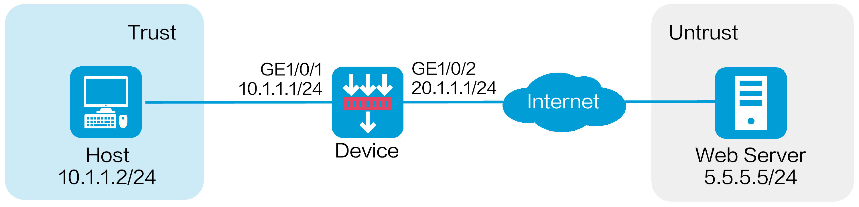
As shown in Figure 1, the device acts as the security gateway. Configure the IPS feature to meet the following requirements:
· Protect the internal network from the vulnerability attacks from the Internet.
· Allow the internal users to use the application that matches the IPS signature with signature ID 936.
Software versions used
This configuration example was created and verified on R8860 of the F1000-AI-55 device.
Procedure
1. Assign IP addresses to interfaces:
# On the top navigation bar, click Network.
# From the navigation pane, select Interface Configuration > Interfaces.
# Click the Edit icon for GE 1/0/1.
# In the dialog box that opens, configure the interface:
a. Select the Trust security zone.
b. Click the IPv4 Address tab, and then enter the IP address and mask length of the interface. In this example, enter 10.1.1.1/24.
c. Use the default settings for other parameters.
d. Click OK.
# Add GE 1/0/2 to the Untrust security zone and set its IP address to 20.1.1.1./24 in the same way you configure GE 1/0/1.
2. Configure routing settings.
This example configures a static route. To use dynamic routing, configure dynamic routing protocols as required.
Configure the next hop IP address to reach the Web server in the external network according to the actual network conditions. In this example, the next hop IP address is 20.1.1.2.
To configure a static route:
# On the top navigation bar, click Network.
# From the navigation pane, select Routing > Static Routing.
# On the IPv4 Static Routing tab, click Create.
# In the dialog box that opens, configure a static IPv4 route to reach 0.0.0.0:
¡ Enter destination IP address 5.5.5.0.
¡ Enter mask length 24.
¡ Enter next hop address 20.1.1.2.
¡ Use the default settings for other parameters.
# Click OK.
3. Update the IPS signature library to the latest version. (Details not shown.)
4. Configure an IPS profile:
# On the top navigation bar, click Objects.
# From the navigation pane, select APP Security > IPS > Profiles.
# Click Create.
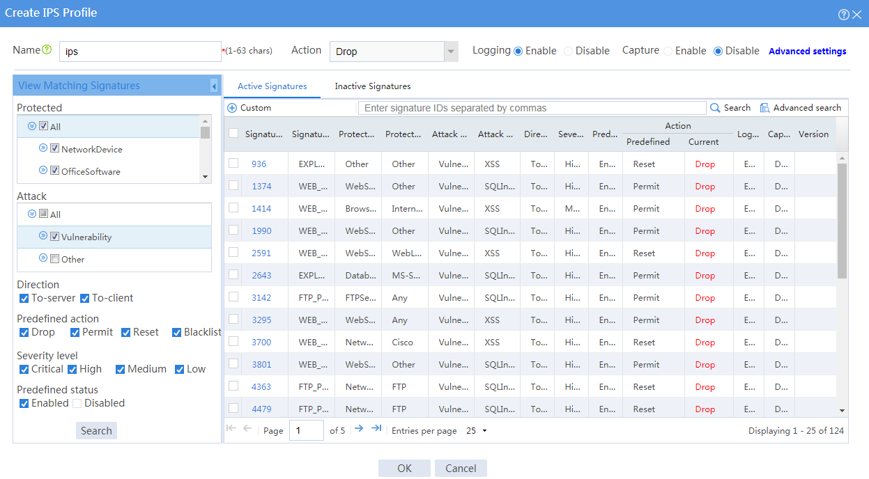
# In the dialog box that opens, configure an IPS profile:
¡ Enter the name ips.
¡ In the View Matching Signatures area, configure the following settings:
- Select All for the protected target.
- Select Vulnerability for the attack categories.
- Set To-server and To-client for the direction.
- Set the predefined action to drop, permit, reset and blacklist.
- Set the severity level to critical, high, medium, and low.
- Enable the predefined status.
¡ In the Action area on the top of the page, configuration the actions:
- Select Drop from the action list.
- Enable logging.
- Use the default settings for other parameters.
Figure 2 Creating an IPS profile
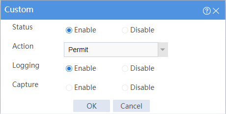
# In the active signature list, select signature 936, and click Custom. In the dialog box that opens, configure the following parameters:
¡ Set the status to Enable.
¡ Select Permit from the action list.
¡ Enable logging.
¡ Use the default settings for other parameters.
Figure 3 Customizing the signature
# Click OK.
# Click OK.
5. Create security policies:
# On the top navigation bar, click Policies.
# From the navigation pane, select Security Policies > Security Policies.
# Click Create , and then click Create a policy.
# In the dialog box that opens, configure a security policy named untrust-trust to permit the specified traffic from the Untrust to Trust security zones:
¡ Enter policy name untrust-trust.
¡ Select source zone Untrust.
¡ Select destination zone Trust.
¡ Select type IPv4.
¡ Select action Permit.
¡ Select destination IP address 10.1.1.0/24.
¡ Select IPS profile ips in the Content security area.
¡ Use the default settings for other parameters.
# Click OK.
# Create security policy trust-untrust to permit the specified traffic from the Trust to Untrust security zones:
¡ Enter policy name trust-untrust.
¡ Select source zone Trust.
¡ Select destination zone Untrust.
¡ Select type IPv4.
¡ Select action Permit.
¡ Select source IP address 10.1.1.0/24.
¡ Select IPS profile ips in the Content security area.
¡ Use the default settings for other parameters.
# Click OK.
6. Activate the settings on the Security Policies page:
# After you apply the IPS profile to the security policy, click Submit (the second Submit in Figure 4) to have the content security configuration take effect.
# Click Activate (the first Submit in Figure 4) to activate security policy matching acceleration.
Figure 4 Activate security policy settings

7. Enable logging:
# On the top navigation bar, click System.
# From the navigation pane, select Log Settings > Basic Settings.
# Click the Storage Space Settings tab.
# Edit the storage space settings for the IPS service and enable logging for the service.
Verifying the configuration
Verify that IPS can implement the following protection for the internal network:
· Log and block the vulnerability attacks.
· Allow the internal users to use the application that matches IPS signature 936.
To view the logs generated for these events, click Monitor on the top navigation bar, and then select Security Logs > Threat Logs from the navigation pane.