- Table of Contents
-
- 09-Configuration Examples
- 01-Web Login Configuration Examples
- 02-Internet Access Through a Static IP Address Configuration Examples
- 03-Internet access through PPPoE configuration examples
- 04-License Configuration Examples
- 05-Signature Library Upgrade Configuration Examples
- 06-Software Upgrade Examples
- 06-Software Upgrade Examples (only for F50X0-D and F5000-AK5X5 firewalls)
- 07-Routing deployment configuration examples
- 08-Transparent deployment configuration examples
- 09-Static routing configuration examples
- 10-RIP configuration examples
- 11-OSPF configuration examples
- 12-BGP configuration examples
- 13-Policy-based routing configuration examples
- 14-Security Policy Configuration Examples
- 15-APR-Based Security Policy Configuration Examples
- 16-Object Group Configuration Examples
- 17-User identification configuration examples
- 18-Attack defense configuration examples
- 19-IPCAR Configuration Examples
- 20-IPS Configuration Examples
- 21-URL Filtering Configuration Examples
- 22-Anti-Virus Configuration Examples
- 23-File Filtering Configuration Examples
- 24-Data Filtering Configuration Examples
- 25-WAF Configuration Examples
- 26-IP Reputation Configuration Examples
- 27-APT Defense Configuration Examples
- 28-NetShare Control Configuration Examples
- 29-Bandwidth Management Configuration Examples
- 30-IPsec configuration examples
- 31-SSL VPN IP access configuration examples
- 31-SSL VPN TCP access configuration examples
- 31-SSL VPN Web access configuration examples
- 32-L2TP Configuration Examples
- 33-NAT configuration examples
- 34-NPTv6 Configuration Examples
- 35-Policy-based NAT configuration examples
- 36-NAT hairpin configuration examples
- 37-NAT Flow Logging Configuration Examples
- 38-Inbound Link Load Balancing Configuration Examples
- 39-Outbound Link Load Balancing Configuration Examples
- 40-Server Load Balancing Configuration Examples
- 41-Transparent DNS Proxy Configuration Examples
- 42-High Availability Group Configuration Examples
- 43-Context Configuration Examples
- 43-Context Configuration Examples(only for F50X0-D and F5000-AK5X5 firewalls)
- 44-IRF configuration examples
- 44-IRF configuration examples(only for F50X0-D and F5000-AK5X5 firewalls)
- 45-DHCP configuration examples
- 46-DNS configuration examples
- 47-Server Connection Detection Configuration Examples
- 48-Connection Limit Configuration Examples
- 49-Public key management configuration examples
- 50-SSL Decryption Configuration Examples
- 51-MAC Address Learning Through a Layer 3 Device Configuration Examples
- 52-4G Configuration Examples
- 53-WLAN Configuration Examples
- Related Documents
-
| Title | Size | Download |
|---|---|---|
| 39-Outbound Link Load Balancing Configuration Examples | 1.13 MB |
Outbound link load balancing configuration examples
Contents
· Example: Configuring application-based outbound link load balancing
· Example: Configuring ISP-based outbound link load balancing
The following information provides outbound link load balancing configuration examples.
This document is not restricted to specific software or hardware versions. Procedures and information in the examples might be slightly different depending on the software or hardware version of the device.
The configuration examples were created and verified in a lab environment, and all the devices were started with the factory default configuration. When you are working on a live network, make sure you understand the potential impact of every command on your network.
The following information is provided based on the assumption that you have basic knowledge of the outbound link load balancing feature.
Network configuration
ISP 1 and ISP 2 provide an enterprise with two links, Link 1 and Link 2. Both links have the same router hop count, bandwidth, and cost.
Configure outbound link load balancing to meet the following requirements:
· The traffic for SoHu video application is distributed to link Link1.
· The traffic for all other application is distributed to link Link2.
Software versions used
This configuration example was created and verified on R8860 of the F1000-AI-55 device.
Procedures
1. Assign IP addresses to interfaces and add the interfaces to security zones.
# On the top navigation bar, click the Network tab.
# From the navigation pane, select Interface Configuration > Interfaces.
# Click the Edit icon for GE 1/0/1.
# In the dialog box that opens, configure the interface:
¡ Select the Untrust security zone.
¡ On the IPv4 Address tab, enter the IP address and mask length of the interface. In this example, enter 30.1.1.1/24.
¡ Use the default settings for other parameters.
¡ Click OK.
# Add GE 1/0/2 to the Untrust security zone and set its IP address to 20.1.1.1./24 in the same way you configure GE 1/0/1.
# Add GE 1/0/3 to the Trust security zone and set its IP address to 192.168.100.82/24 in the same way you configure GE 1/0/1.
2. Configure security policies.
# On the top navigation bar, click Policies.
# From the navigation pane, select Security Policies > Security Policies.
# Click Create.
# In the dialog box that opens, configure a security policy named Trust-to-Untrust:
¡ Enter policy name Trust-to-Untrust.
¡ Select source zone Trust.
¡ Select destination zone Untrust.
¡ Select type IPv4.
¡ Select action Permit.
¡ Enter source IPv4 address 192.168.100.0/24.
¡ Use the default settings for other parameters.
¡ Click OK.
# Configure a security policy named Local-to-Untrust:
¡ Enter policy name Local-to-Untrust.
¡ Select source zone Local.
¡ Select destination zone Untrust.
¡ Select type IPv4.
¡ Select action Permit.
¡ Enter destination IPv4 addresses 20.1.1.0/24 and 30.1.1.0/24.
¡ Use the default settings for other parameters.
¡ Click OK.
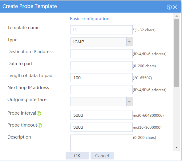
3. Configure an ICMP probe template.
# On the top navigation bar, click Objects.
# From the navigation pane, click Health Monitoring.
# Click Create.
# In the dialog box that opens, configure an ICMP probe template:
a. Enter template name t1.
b. Select type ICMP.
c. Enter 100 for the Length of data to pad field.
d. Enter 5000 for the Probe interval field.
e. Enter 3000 for the Probe timeout field.
f. Click OK.
Figure 2 Creating probe template t1
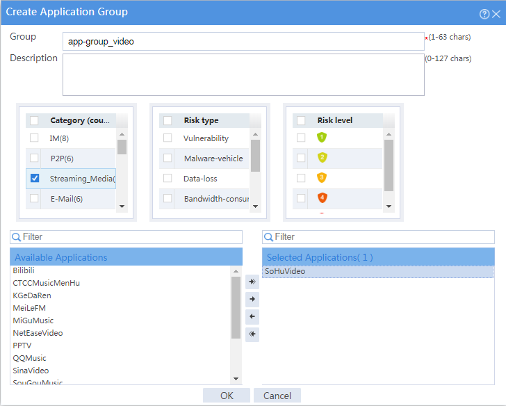
4. Configure an application group.
# On the top navigation bar, click Objects.
# From the navigation pane, select APPSecurity > APP Recognition > Application Groups.
# Click Create.
# In the dialog box that opens, configure an application group named app-group_video:
¡ Enter group name app-group_video.
¡ Add application SoHuVideo in the Streaming_Media category to the Selected Applications pane.
¡ Click OK.
Figure 3 Creating an application group
5. Configure links.
# On the top navigation bar, click Polices.
# From the navigation pane, select Load Balancing > Common Configuration > Links.
# Click Create.
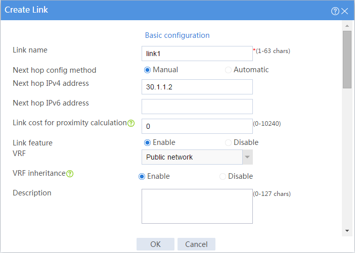
# In the dialog box that opens, configure a link named link1:
¡ Enter link name link1.
¡ Select Manual for the Next hop config method field.
¡ Enter next hop IPv4 address 30.1.1.2.
¡ Set the link cost for proximity calculation to 0.
¡ Enable the link feature.
¡ Enable VRF inheritance.
¡ Click OK.
Figure 4 Creating link link1
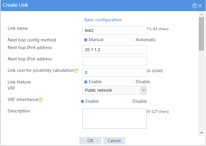
# Configure link link2 in the same way you configure link link1.
Figure 5 Creating link link2
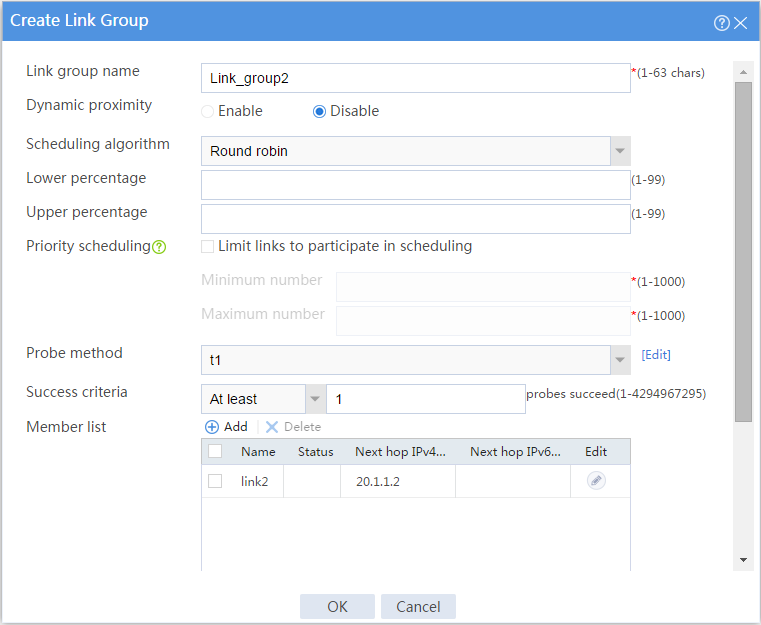
6. Configure link groups.
# On the top navigation bar, click Polices.
# From the navigation pane, select Load Balancing > Link Load Balancing > Outbound Link LB.
# On the Link Group tab, click Create.
# In the dialog box that opens, configure a link group named Link_group1:
¡ Enter link group name Link_group1.
¡ Disable dynamic proximity.
¡ Select scheduling algorithm Round robin.
¡ Select probe method t1.
¡ Set the success criteria to At least 1.
¡ Add link link1 to the link group.
¡ Click OK.
Figure 6 Creating link group Link_group1

# Configure link group Link_group2 in the same way you configure link group Link_group1.
Figure 7 Creating link group Link_group2
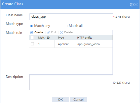
7. Configure a class.
# On the top navigation bar, click Polices.
# From the navigation pane, select Load Balancing > Link Load Balancing > Outbound Link LB.
# On the Class tab, click Create.
# In the dialog box that opens, configure a class named class_app:
¡ Enter class name class_app.
¡ Select Match any for the Match type field.
¡ Add application group app-group_video as a match rule.
¡ Click OK.
Figure 8 Creating class class_app
8. Configure IPv4 routing policies.
# On the top navigation bar, click Polices.
# From the navigation pane, select Load Balancing > Link Load Balancing > Outbound Link LB.
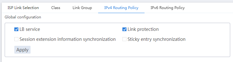
# In the Global configuration area on the IPv4 Routing Policy tab, enable LB service and Link protection.
Figure 9 Global configuration
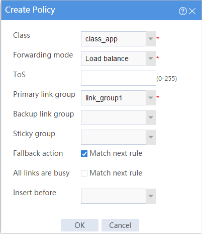
# In the Policy area on the IPv4 Routing Policy tab, click Create.
# In the dialog box that opens, configure an IPv4 routing policy:
¡ Select name class-app.
¡ Select forwarding mode Load balance.
¡ Select primary link group link_group1.
¡ Select Match next rule for the Fallback action field.
¡ Click OK.
Figure 10 Creating class class-app
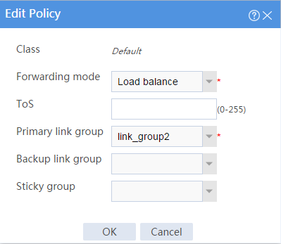
# In the Policy area on the IPv4 Routing Policy tab, click the Edit icon for the default IPv4 routing policy named Default.
# In the dialog box that opens, configure the default IPv4 routing policy:
¡ Select forwarding mode Load balance.
¡ Select primary link group link_group2.
¡ Click OK.
Figure 11 Editing the default IPv4 routing policy
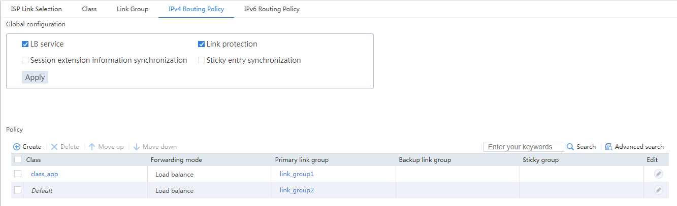
The IPv4 routing policy configuration is as follows:
Figure 12 IPv4 routing policy configuration
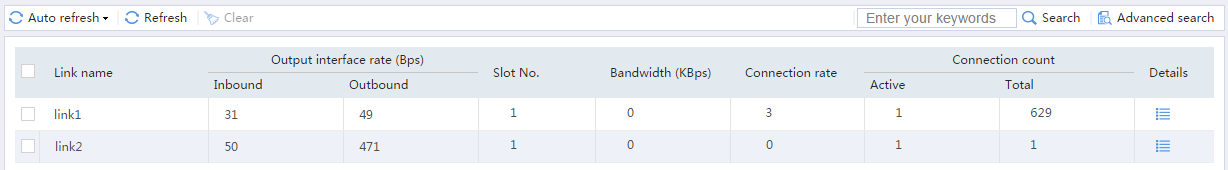
Verifying the configuration
1. Open the Sohu video client, and select a movie to play.
2. Verify that the traffic for the Sohu video client is transmitted over link link1:
# On the top navigation bar, click the Monitor tab.
# From the navigation pane, select Statistics > Outbound Link LB Statistics > Links.
The Link Statistics page is as follows:
Figure 13 Link statistics
Example: Configuring ISP-based outbound link load balancing
Network configuration
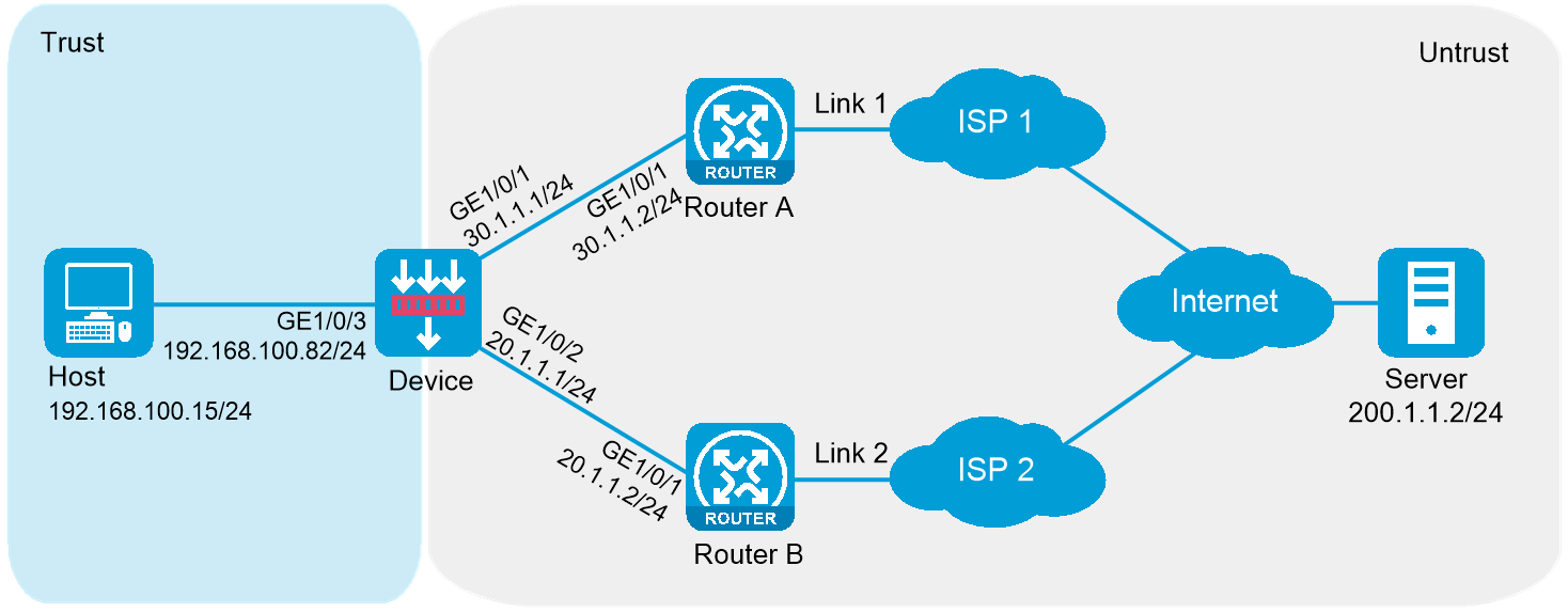
As shown in Figure 14, an enterprise accesses the external servers through ISP links Link_a, Link_b, and Link_c provided by ISP_A, ISP_B, and ISP_C, respectively. Configure outbound link load balancing to meet the following requirements:
· The LB device distributes outbound traffic to external servers matching ISP_A, ISP_B, and ISP_C through Link_a, Link_b, and Link_c, respectively.
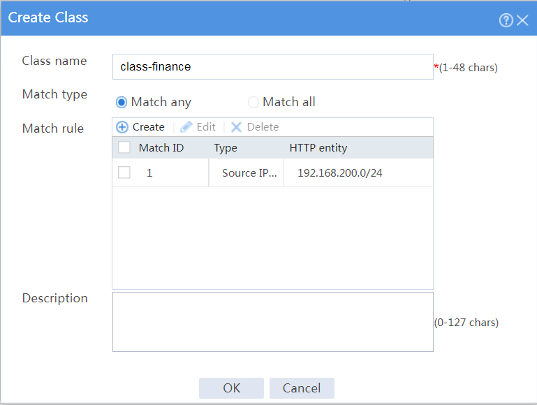
· Host B (with IP address 192.168.200.0/24 in the finance department) needs to access online payment services. To avoid frequent egress IP address changes, the LB device distributes finance data traffic through Link_a. When the bandwidth usage on Link_a exceeds, the LB device distributes consequent traffic to Link_b.
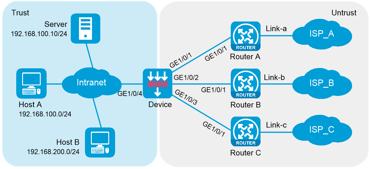
|
Device |
Interface |
IP address |
Device |
Interface |
IP address |
|
Device |
GE1/0/1 |
30.1.1.1/24 |
Router A |
GE1/0/1 |
30.1.1.2/24 |
|
Device |
GE1/0/2 |
20.1.1.1/24 |
Router B |
GE1/0/1 |
20.1.1.2/24 |
|
Device |
GE1/0/3 |
10.1.1.124 |
Router C |
GE1/0/1 |
10.1.1.2/24 |
|
Device |
GE1/0/4 |
192.168.100.82/24 |
|
|
|
Software versions used
This configuration example was created and verified on R8860 of the F1000-AI-55 device.
Procedures
1. Assign IP addresses to interfaces and add the interfaces to security zones.
# On the top navigation bar, click the Network tab.
# From the navigation pane, select Interface Configuration > Interfaces.
# Click the Edit icon for GE 1/0/1.
# In the dialog box that opens, configure the interface:
¡ Select the Untrust security zone.
¡ On the IPv4 Address tab, enter the IP address and mask length of the interface. In this example, enter 30.1.1.1/24.
¡ Use the default settings for other parameters.
¡ Click OK.
# Add GE 1/0/2 to the Untrust security zone and set its IP address to 20.1.1.1./24 in the same way you configure GE 1/0/1.
# Add GE 1/0/3 to the Untrust security zone and set its IP address to 10.1.1.1/24 in the same way you configure GE 1/0/1.
# Add GE 1/0/4 to the Trust security zone and set its IP address to 192.168.100.82/24 in the same way you configure GE 1/0/1.
2. Configure routes:
This section uses static routes as an example. You can also configure a dynamic routing protocol as needed.
# On the top navigation bar, click Network.
# From the navigation pane, select Routing > Static Routing.
# On the IPv4 Static Routing tab, click Create.
# In the dialog box that opens, configure an IPv4 static route with next hop IP address 30.1.1.2:
¡ Enter destination IP address 0.0.0.0.
¡ Enter mask length 0.
¡ Enter next hop IP address 30.1.1.2.
¡ Use the default settings for other parameters.
¡ Click OK.
# On the IPv4 Static Routing tab, click Create.
# In the dialog box that opens, configure an IPv4 static route with next hop IP address 20.1.1.2:
¡ Enter destination IP address 0.0.0.0.
¡ Enter mask length 0.
¡ Enter next hop IP address 20.1.1.2.
¡ Use the default settings for other parameters.
¡ Click OK.
# On the IPv4 Static Routing tab, click Create.
# In the dialog box that opens, configure an IPv4 static route with next hop IP address 10.1.1.2:
¡ Enter destination IP address 0.0.0.0.
¡ Enter mask length 0.
¡ Enter next hop IP address 10.1.1.2.
¡ Use the default settings for other parameters.
¡ Click OK.
3. Configure security policies.
# On the top navigation bar, click Policies.
# From the navigation pane, select Security Policies > Security Policies.
# Click Create.
# In the dialog box that opens, configure a security policy named Trust-to-Untrust:
¡ Enter policy name Trust-to-Untrust.
¡ Select source zone Trust.
¡ Select destination zone Untrust.
¡ Select type IPv4.
¡ Select action Permit.
¡ Enter source IPv4 addresses 192.168.100.0/24 and 192.168.200.0/24.
¡ Use the default settings for other parameters.
¡ Click OK.
# Configure a security policy named Local-to-Untrust:
¡ Enter policy name Local-to-Untrust.
¡ Select source zone Local.
¡ Select destination zone Untrust.
¡ Select type IPv4.
¡ Select action Permit.
¡ Enter destination IPv4 addresses 10.1.1.0/24, 20.1.1.0/24, and 30.1.1.0/24.
¡ Use the default settings for other parameters.
¡ Click OK.
4. Configure ICMP probe templates.
# On the top navigation bar, click Objects.
# From the navigation pane, click Health Monitoring.
# Click Create.
# In the dialog box that opens, configure an ICMP probe template named ta, as shown in Figure 15.
Figure 15 Creating probe template ta
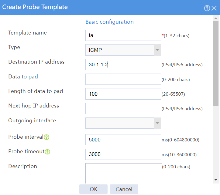
# Click OK.
# Configure an ICMP probe template named tb, as shown in Figure 16.
Figure 16 Creating probe template tb
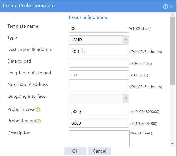
# Click OK.
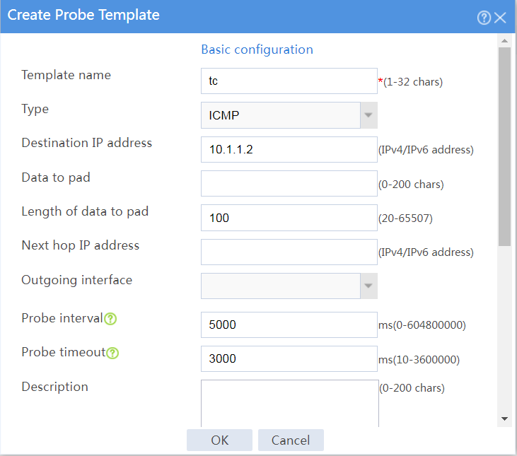
# Configure an ICMP probe template named tc, as shown in Figure 17.
Figure 17 Creating probe template tc
# Click OK.
5. Configure outbound dynamic NAT rules.
# On the top navigation bar, click Policies.
# From the navigation pane, select Interface NAT > IPv4 > Dynamic NAT.
# On the Outbound Dynamic NAT (Object Group-Based) tab, click Create.
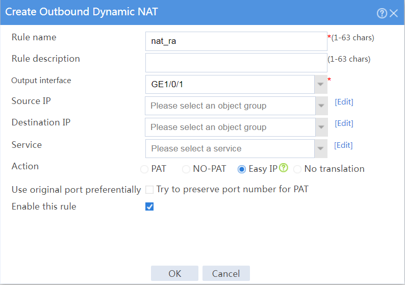
# Create an outbound dynamic NAT rule named nat_ra, as shown in Figure 18:
¡ Enter rule name nat_ra.
¡ Select output interface GE1/0/1.
¡ Select action Easy IP.
¡ Select Enable this rule.
¡ Click OK.
Figure 18 Configuring an outbound dynamic NAT rule named nat_ra
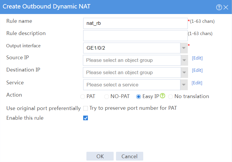
# Create an outbound dynamic NAT rule named nat_rb, as shown in Figure 19:
¡ Enter rule name nat_rb.
¡ Select output interface GE1/0/2.
¡ Select action Easy IP.
¡ Select Enable this rule.
¡ Click OK.
Figure 19 Configuring an outbound dynamic NAT rule named nat_rb
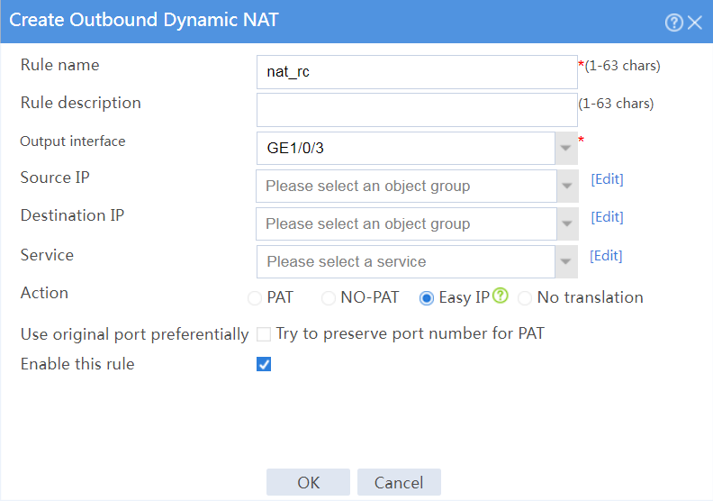
# Create an outbound dynamic NAT rule named nat_rc, as shown in Figure 20:
¡ Enter rule name nat_rc.
¡ Select output interface GE1/0/3.
¡ Select action Easy IP.
¡ Select Enable this rule.
¡ Click OK.
Figure 20 Configuring an outbound dynamic NAT rule named nat_rc
6. Configure links.
# On the top navigation bar, click Polices.
# From the navigation pane, select Load Balancing > Common Configuration > Links.
# Click Create.
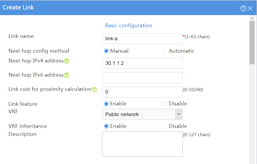
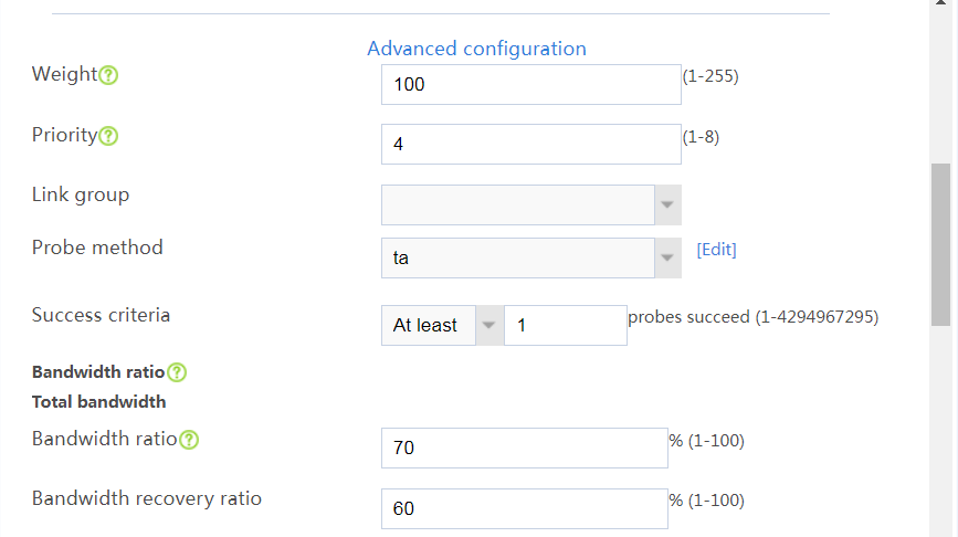
# In the dialog box that opens, configure a link named link-a as shown in Figure 21.
# Click OK.
Figure 21 Creating link link-a

# Click Create.
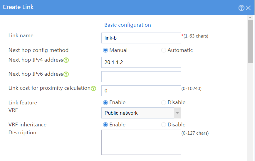
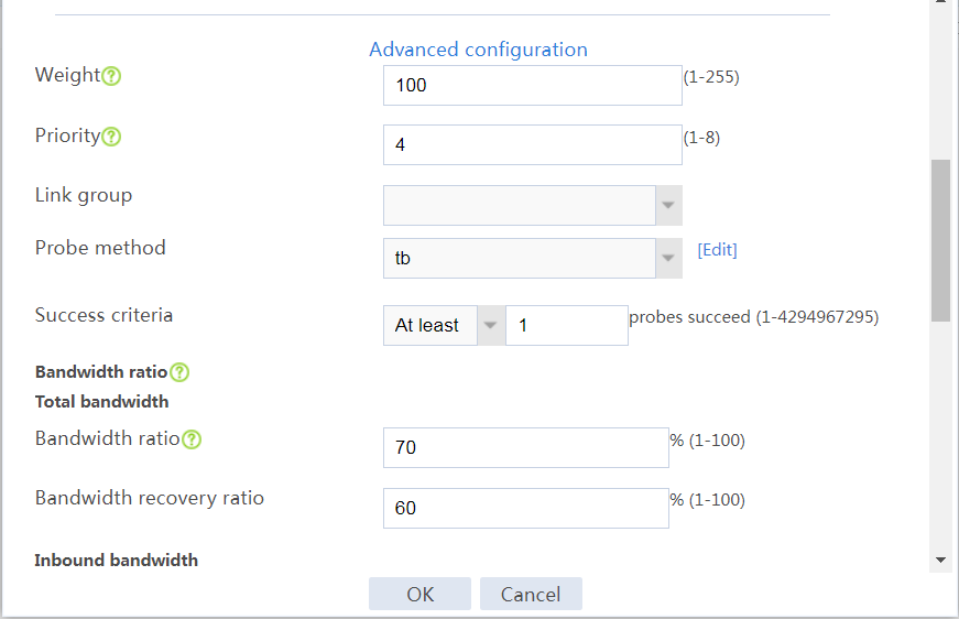
# In the dialog box that opens, configure a link named link-b as shown in Figure 22.
# Click OK.
Figure 22 Creating link link-b
# Click Create.
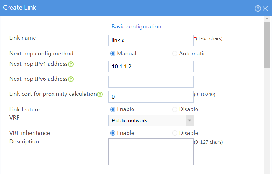
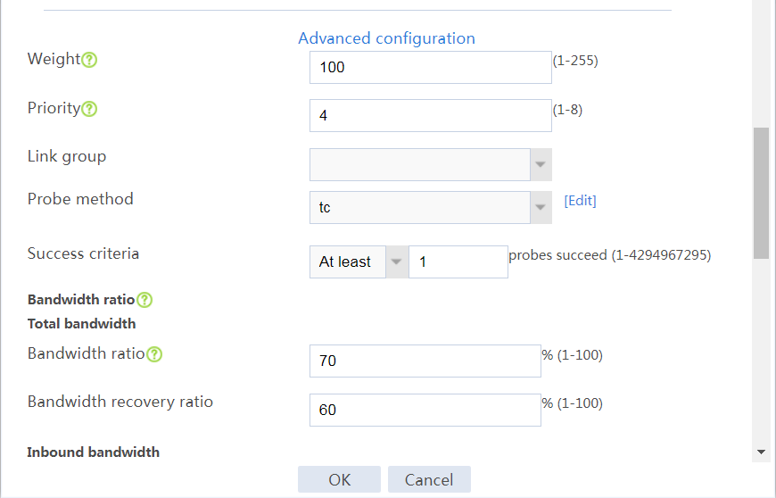
# In the dialog box that opens, configure a link named link-c as shown in Figure 23.
# Click OK.
Figure 23 Creating link link-c

7. Configure link groups.
# On the top navigation bar, click Polices.
# From the navigation pane, select Load Balancing > Link Load Balancing > Outbound Link LB.
# On the Link Group tab, click Create.
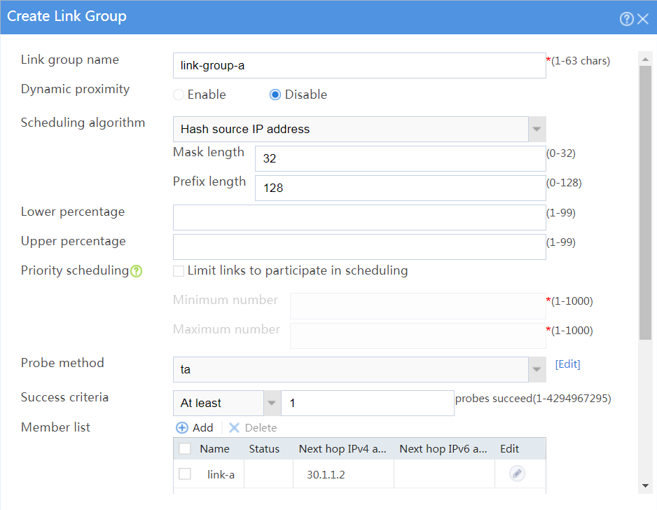
# In the dialog box that opens, configure a link group named link-group-a as shown in Figure 24.
# Click OK.
Figure 24 Creating link group link-group-a

# On the Link Group tab, click Create.
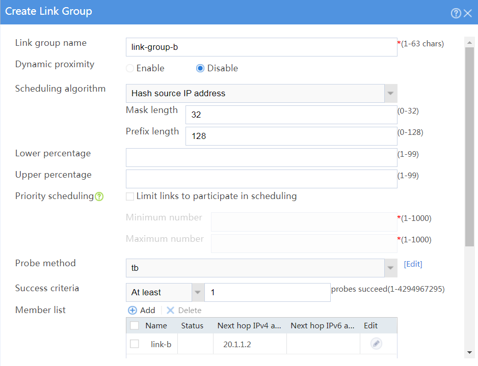
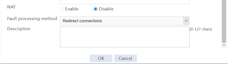
# In the dialog box that opens, configure a link group named link-group-b as shown in Figure 25.
# Click OK.
Figure 25 Creating link group link-group-b
# On the Link Group tab, click Create.
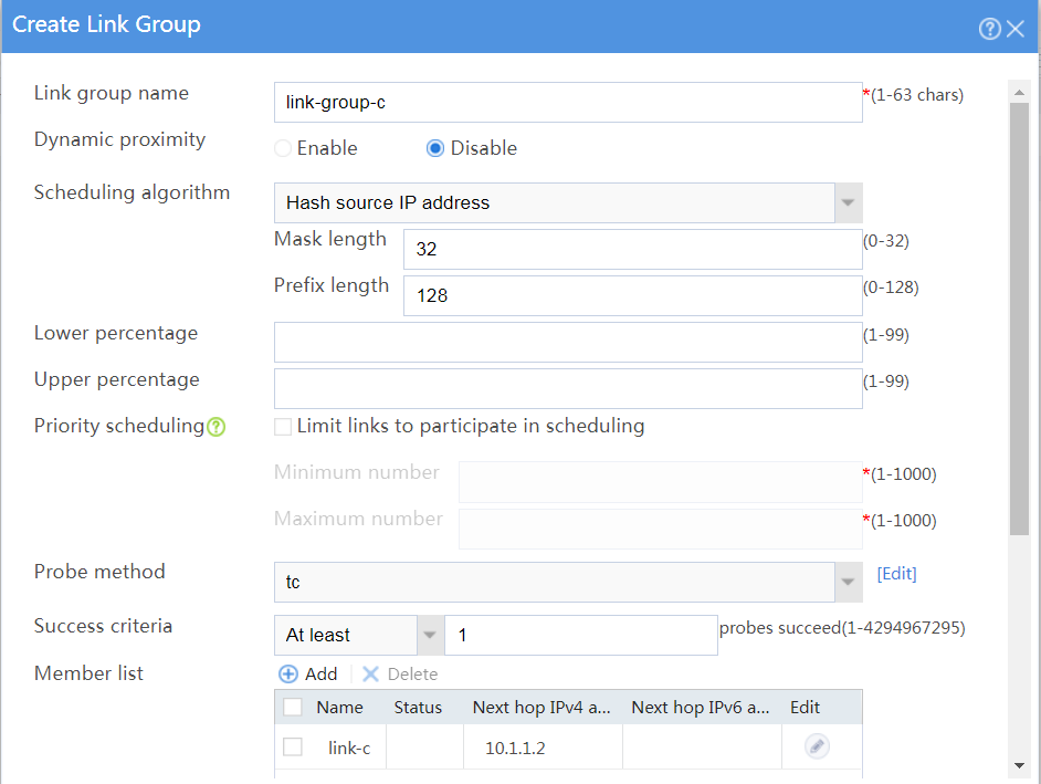
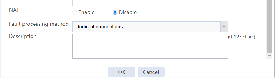
# In the dialog box that opens, configure a link group named link-group-c as shown in Figure 26
# Click OK.
Figure 26 Creating link group link-group-c
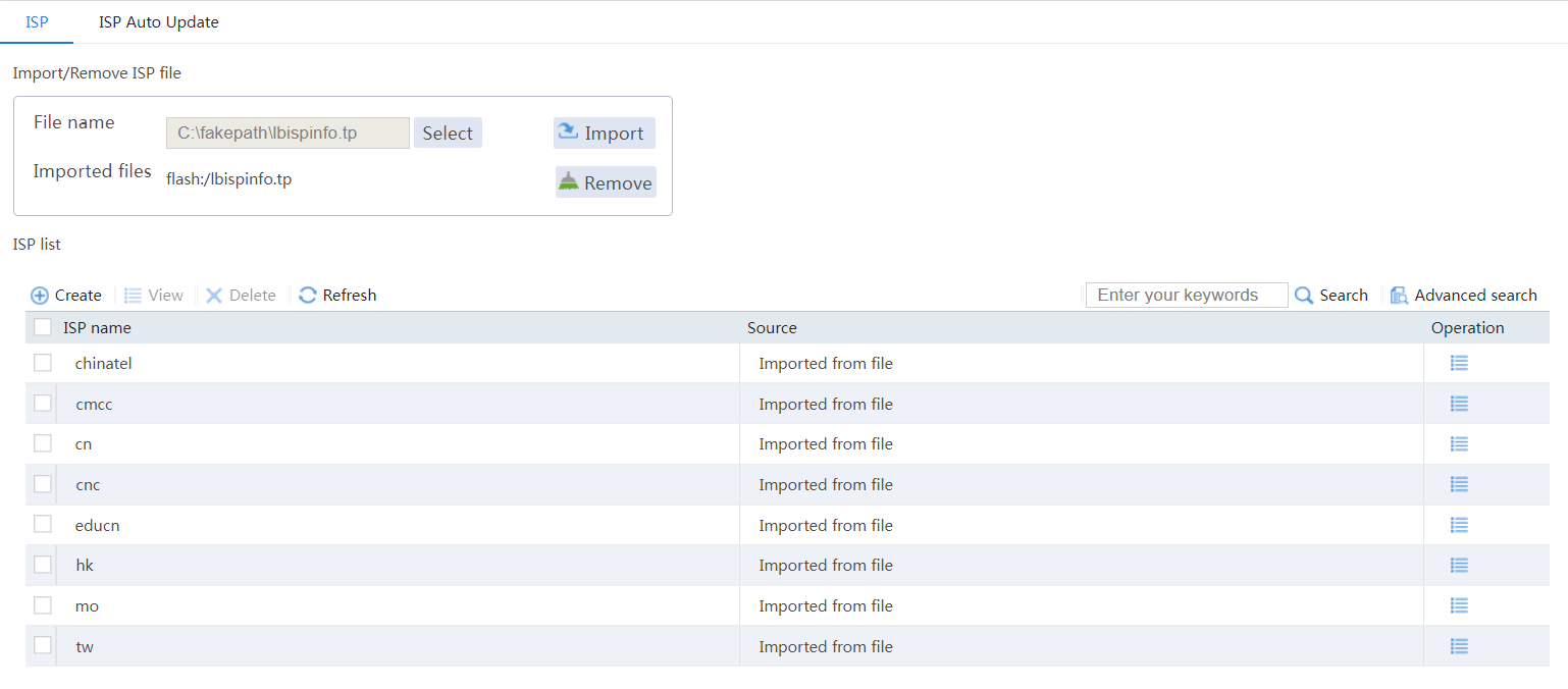
8. Import ISP information.
# On the top navigation bar, click Polices.
# From the navigation pane, select Load Balancing > Common Configuration > ISP.
# Select file lbispinfo.tp.
# Click Import.
Figure 27 Importing ISP information
9. Configure classes.
# On the top navigation bar, click Polices.
# From the navigation pane, select Load Balancing > Link Load Balancing > Outbound Link LB.
# On the Class tab, click Create.
# In the dialog box that opens, configure a class named class-isp-a as shown in Figure 28.
# Click OK.
Figure 28 Creating class class-isp-a
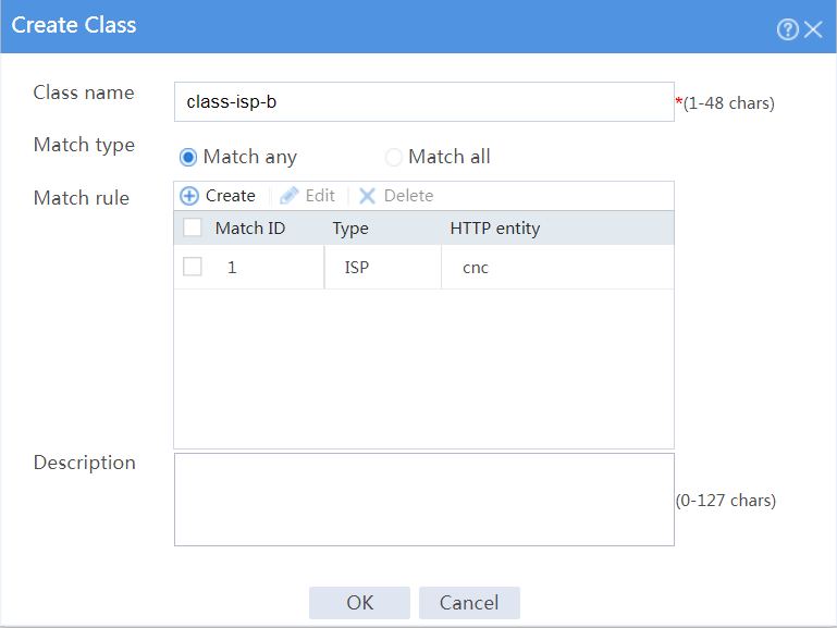
# On the Class tab, click Create.
# In the dialog box that opens, configure a class named class-isp-b as shown in Figure 29.
# Click OK.
Figure 29 Creating class class-isp-b
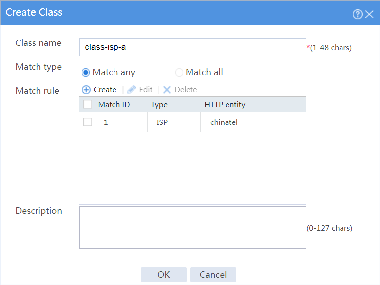
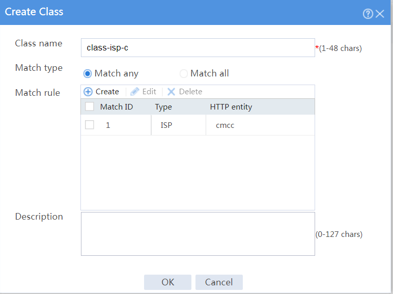
# On the Class tab, click Create.
# In the dialog box that opens, configure a class named class-isp-c as shown in Figure 30.
# Click OK.
Figure 30 Creating class class-isp-c
# On the Class tab, click Create.
# In the dialog box that opens, configure a class named class-finance as shown in Figure 31.
# Click OK.
Figure 31 Creating class class-finance
10. Configure IPv4 routing policies.
# On the top navigation bar, click Polices.
# From the navigation pane, select Load Balancing > Link Load Balancing > Outbound Link LB.
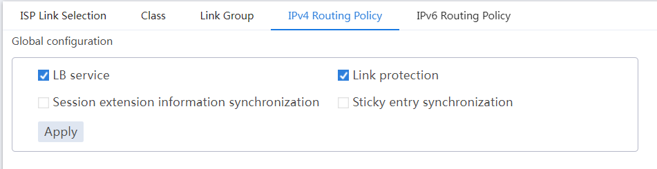
# In the Global configuration area on the IPv4 Routing Policy tab, select LB service and Link protection.
Figure 32 Global configuration
# In the Policy area on the IPv4 Routing Policy tab, click Create.
# In the dialog box that opens, configure an IPv4 routing policy for class class-finance:
¡ Select class class-finance.
¡ Select forwarding mode Load balance.
¡ Select primary link group link-group-a.
¡ Select Match next rule for the Fallback action field.
¡ Click OK.
Figure 33 Creating a policy for class class-finance

# In the Policy area on the IPv4 Routing Policy tab, click Create.
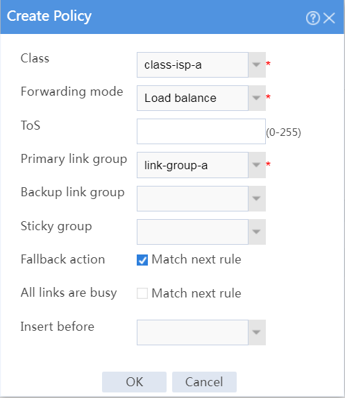
# In the dialog box that opens, configure an IPv4 routing policy for class class-isp-a:
¡ Select class class-isp-a.
¡ Select forwarding mode Load balance.
¡ Select primary link group link-group-a.
¡ Select Match next rule for the Fallback action field.
¡ Click OK.
Figure 34 Creating a policy for class class-isp-a
# In the Policy area on the IPv4 Routing Policy tab, click Create.
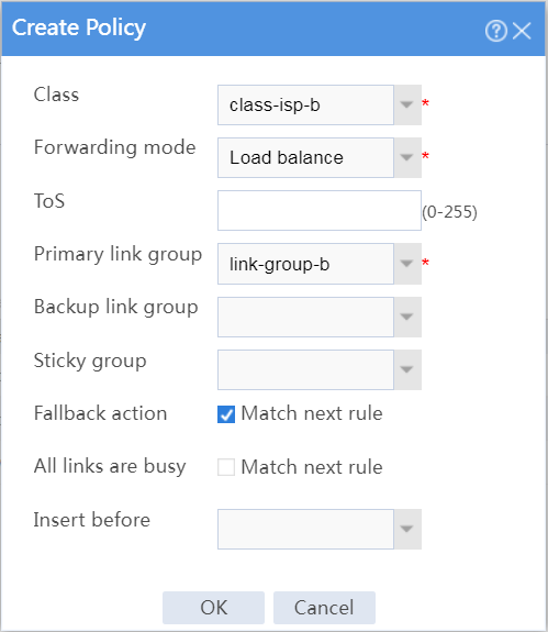
# In the dialog box that opens, configure an IPv4 routing policy for class class-isp-b:
¡ Select class class-isp-b.
¡ Select forwarding mode Load balance.
¡ Select primary link group link-group-b.
¡ Select Match next rule for the Fallback action field.
¡ Click OK.
Figure 35 Creating a policy for class class-isp-b
# In the Policy area on the IPv4 Routing Policy tab, click Create.
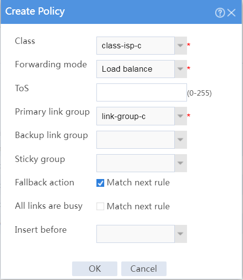
# In the dialog box that opens, configure an IPv4 routing policy for class class-isp-c:
¡ Select class class-isp-c.
¡ Select forwarding mode Load balance.
¡ Select primary link group link-group-c.
¡ Select Match next rule for the Fallback action field.
¡ Click OK.
Figure 36 Creating a policy for class class-isp-c
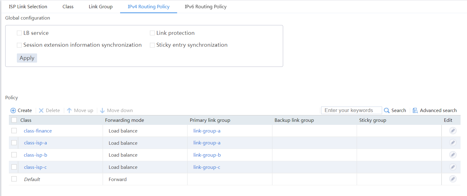
# View the configured IPv4 routing policies as shown in Figure 37.
Figure 37 IPv4 routing policies
Verifying the configuration
# On the top navigation bar, click the Monitor tab.
# From the navigation pane, select Statistics > Outbound Link LB Statistics > Links.
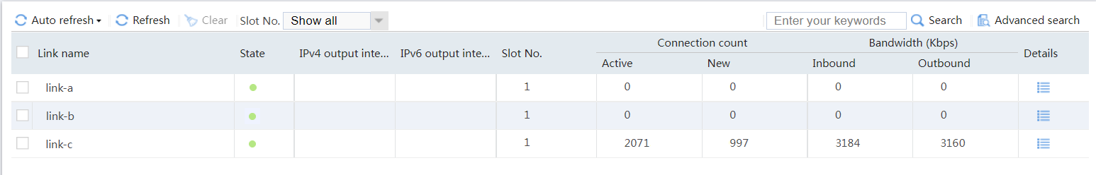
# View the statistics of link link-a as shown in Figure 38. Traffic from subnet 192.168.200.0/24 in the finance department matches class class-finance, and is distributed to link group link-group-a.
Figure 38 Statistics of traffic from the finance department
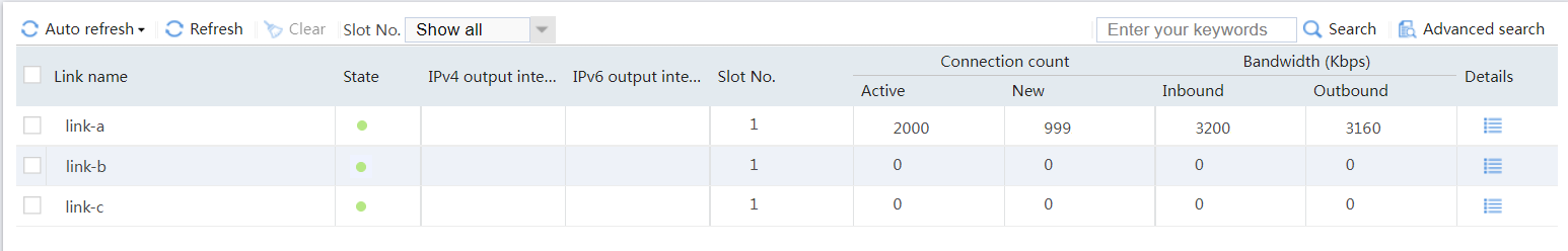
# View the statistics of link link-a as shown in Figure 39. Traffic destined for ISP-A matches class class-isp-a, and is distributed to link group link-group-a.
Figure 39 Statistics of traffic destined for ISP_A
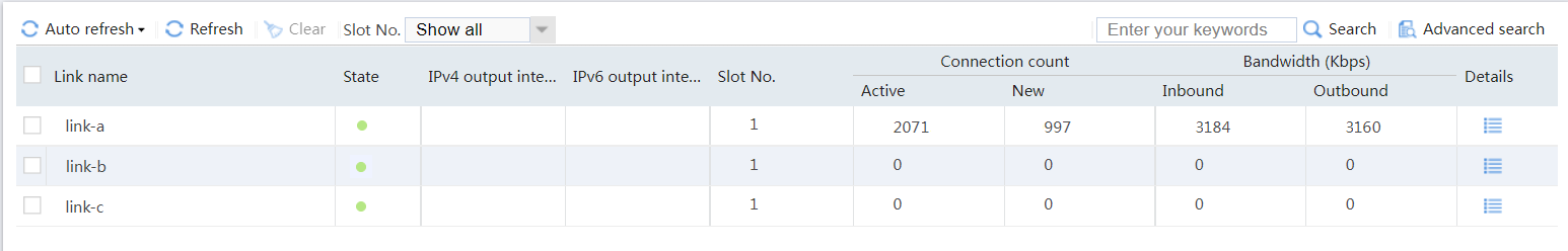
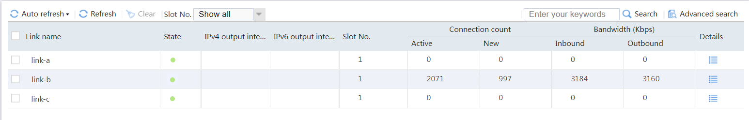
# View the statistics of link link-b as shown in Figure 40. Traffic destined for ISP-B belongs to class class-isp-b, and is distributed to link group link-group-b.
Figure 40 Statistics of traffic destined for ISP_B
# View the statistics of link link-c as shown in Figure 41. Traffic destined for ISP_C belongs to class class-isp-c, and is distributed to link group link-group-c.
Figure 41 Statistics of traffic destined for ISP_C