- Table of Contents
-
- 09-Configuration Examples
- 01-Web Login Configuration Examples
- 02-Internet Access Through a Static IP Address Configuration Examples
- 03-Internet access through PPPoE configuration examples
- 04-License Configuration Examples
- 05-Signature Library Upgrade Configuration Examples
- 06-Software Upgrade Examples
- 06-Software Upgrade Examples (only for F50X0-D and F5000-AK5X5 firewalls)
- 07-Routing deployment configuration examples
- 08-Transparent deployment configuration examples
- 09-Static routing configuration examples
- 10-RIP configuration examples
- 11-OSPF configuration examples
- 12-BGP configuration examples
- 13-Policy-based routing configuration examples
- 14-Security Policy Configuration Examples
- 15-APR-Based Security Policy Configuration Examples
- 16-Object Group Configuration Examples
- 17-User identification configuration examples
- 18-Attack defense configuration examples
- 19-IPCAR Configuration Examples
- 20-IPS Configuration Examples
- 21-URL Filtering Configuration Examples
- 22-Anti-Virus Configuration Examples
- 23-File Filtering Configuration Examples
- 24-Data Filtering Configuration Examples
- 25-WAF Configuration Examples
- 26-IP Reputation Configuration Examples
- 27-APT Defense Configuration Examples
- 28-NetShare Control Configuration Examples
- 29-Bandwidth Management Configuration Examples
- 30-IPsec configuration examples
- 31-SSL VPN IP access configuration examples
- 31-SSL VPN TCP access configuration examples
- 31-SSL VPN Web access configuration examples
- 32-L2TP Configuration Examples
- 33-NAT configuration examples
- 34-NPTv6 Configuration Examples
- 35-Policy-based NAT configuration examples
- 36-NAT hairpin configuration examples
- 37-NAT Flow Logging Configuration Examples
- 38-Inbound Link Load Balancing Configuration Examples
- 39-Outbound Link Load Balancing Configuration Examples
- 40-Server Load Balancing Configuration Examples
- 41-Transparent DNS Proxy Configuration Examples
- 42-High Availability Group Configuration Examples
- 43-Context Configuration Examples
- 43-Context Configuration Examples(only for F50X0-D and F5000-AK5X5 firewalls)
- 44-IRF configuration examples
- 44-IRF configuration examples(only for F50X0-D and F5000-AK5X5 firewalls)
- 45-DHCP configuration examples
- 46-DNS configuration examples
- 47-Server Connection Detection Configuration Examples
- 48-Connection Limit Configuration Examples
- 49-Public key management configuration examples
- 50-SSL Decryption Configuration Examples
- 51-MAC Address Learning Through a Layer 3 Device Configuration Examples
- 52-4G Configuration Examples
- 53-WLAN Configuration Examples
- Related Documents
-
| Title | Size | Download |
|---|---|---|
| 35-Policy-based NAT configuration examples | 280.57 KB |
Policy-based NAT configuration examples
Contents
· Example: Configuring static NAT for internal-to-external access
· Example: Configuring dynamic NAT for internal-to-external access
· Example: Configuring bidirectional translation for external-to-internal access through domain name
The following information describes policy-based NAT configuration examples.
Policy-based NAT contains a set of NAT rules to identify and translate matching packets. The packet match criteria include source security zone, destination security zone, source IP address, destination IP address, and service.
Policy-based NAT supports the following types of rules, which are applicable to different scenarios:
· NAT44 rule—Used for NAT translation between IPv4 networks.
· NAT64 rule—Used for NAT translation between IPv4 networks and IPv6 networks.
· NAT66 rule—Used for NAT translation between IPv6 networks.
Policy-based NAT supports the following translation modes:
· Source address translation—Translates the source IP address and source port of packets.
· Destination address translation—Translates the destination IP address and destination port of packets.
· Bidirectional translation—Translates the source IP address, source port, destination IP address, and destination port of packets.
This document is not restricted to specific software or hardware versions. Procedures and information in the examples might be slightly different depending on the software or hardware version of the device.
The configuration examples were created and verified in a lab environment, and all the devices were started with the factory default configuration. When you are working on a live network, make sure you understand the potential impact of every command on your network.
The following information is provided based on the assumption that you have basic knowledge of policy-based NAT.
Do not configure both policy-based NAT and interface-based NAT.
Network configuration
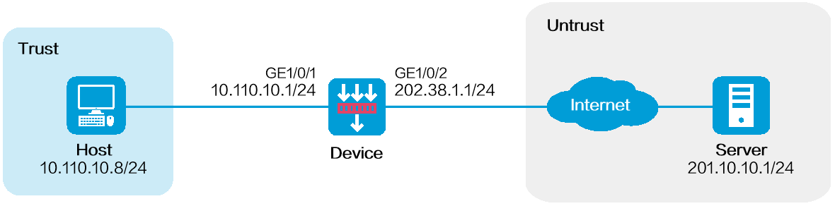
As shown in Figure 1, configure policy-based source address translation to allow the host at 10.110.10.8/24 to access the server at 201.10.10.1/24 on the Internet by using public IP address 202.38.1.100.
Software versions used
This configuration example was created and verified on R8860 of the F1000-AI-55 device.
Procedure
1. Assign IP addresses to interfaces and add the interfaces to security zones.
# On the top navigation bar, click Network.
# From the navigation pane, select Interface Configuration > Interfaces.
# Click the Edit icon for GE 1/0/2.
# In the dialog box that opens, configure the interface:
a. Select the Untrust security zone.
b. On the IPv4 Address tab, enter the IP address and mask of the interface. In this example, enter 202.38.1.1/24.
c. Click OK.
# Add GE 1/0/1 to the Trust security zone and set its IP address to 10.110.10.1/24 in the same way you configure GE 1/0/2.
2. Configure settings for routing.
This example configures a static route. If dynamic routes are required, configure a dynamic routing protocol.
# On the top navigation bar, click Network.
# From the navigation pane, select Routing > Static Routing.
# On the IPv4 Static Routing tab, click Create.
# In the dialog box that opens, configure a static route to permit packets from the device to the server:
a. Specify the IP address of the server as the destination IP. In this example, the address is 201.10.10.1.
b. Enter the mask length. In this example, enter 24.
c. Specify the next-hop address as 202.38.1.2.
d. Click OK.
3. Configure a security policy.
# On the top navigation bar, click Policies.
# From the navigation pane, select Security Policies > Security Policies.
# Click Create and click Create a policy.
# In the dialog box that opens, configure policy parameters as follows:
a. Enter a policy name. In this example, the name is Secpolicy.
b. Select the source zone. In this example, the source zone is Trust.
c. Select the destination zone. In this example, the destination zone is Untrust.
d. Select IPv4 as the type.
e. Select Permit as the action.
f. Specify the IP address of the host as the source IPv4 address. In this example, the address is 10.110.10.8.
g. Specify the IP address of the server as the destination IPv4 address. In this example, the address is 201.10.10.1.
h. Click OK.
4. Create a policy-based NAT rule.
# On the top navigation bar, click Policies.
# From the navigation pane, select Policy-based NAT.
# Click Create.
# Create a policy-based NAT rule, as shown in Figure 2.
Figure 2 Creating a policy-based NAT rule
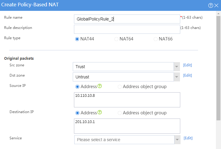
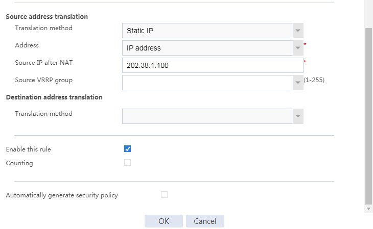
# Click OK.
Verifying the configuration
1. Verify that the host can successfully ping the server on the external network.
C:\Users\abc>ping 201.10.10.1
Pinging host.com [201.10.10.1] with 32 bytes of data:
Reply from 201.10.10.1: bytes=32 time<1ms TTL=253
Reply from 201.10.10.1: bytes=32 time<1ms TTL=253
Reply from 201.10.10.1: bytes=32 time<1ms TTL=253
Reply from 201.10.10.1: bytes=32 time<1ms TTL=253
Ping statistics for 201.10.10.1:
Packets: Sent = 4, Received = 4, Lost = 0 (0% loss),
Approximate round trip times in milli-seconds:
Minimum = 0ms, Maximum = 0ms, Average = 0ms
Example: Configuring dynamic NAT for internal-to-external access
Network configuration
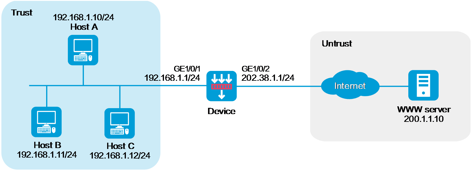
As shown in Figure 3, the company has public addresses 202.38.1.1/24 to 202.38.1.3/24. Configure policy-based source address translation to enable internal hosts to access the server on the Internet.
Software versions used
This configuration example was created and verified on R8860 of the F1000-AI-55 device.
Procedure
1. Assign IP addresses to interfaces and add the interfaces to security zones.
# On the top navigation bar, click Network.
# From the navigation pane, select Interface Configuration > Interfaces.
# Click the Edit icon for GE 1/0/2.
# In the dialog box that opens, configure the interface:
a. Select the Untrust security zone.
b. On the IPv4 Address tab, enter the IP address and mask of the interface. In this example, enter 202.38.1.1/24.
c. Click OK.
# Add GE 1/0/1 to the Trust security zone and set its IP address to 192.168.1.1/24 in the same way you configure GE 1/0/2.
2. Configure settings for routing.
This example configures a static route. If dynamic routes are required, configure a dynamic routing protocol.
# On the top navigation bar, click Network.
# From the navigation pane, select Routing > Static Routing.
# On the IPv4 Static Routing tab, click Create.
# In the dialog box that opens, configure a static route to permit packets from the internal hosts to the external server:
a. Specify the IP address of the server as the destination IP. In this example, the address is 200.1.1.10.
b. Enter the mask length. In this example, enter 24.
c. Specify the next-hop address as 202.38.1.2.
d. Click OK.
3. Configure a security policy.
# On the top navigation bar, click Policies.
# From the navigation pane, select Security Policies > Security Policies.
# Click Create and click Create a policy.
# In the dialog box that opens, configure policy parameters as follows:
a. Enter a policy name. In this example, the name is Secpolicy.
b. Select the source zone. In this example, the source zone is Trust.
c. Select the destination zone. In this example, the destination zone is Untrust.
d. Select IPv4 as the type.
e. Select Permit as the action.
f. Specify the IP addresses of the hosts as the source IPv4 addresses. In this example, the addresses are 192.168.1.10, 192.168.1.11, and 192.168.1.12.
g. Specify the IP address of the server as the destination IPv4. In this example, the address is 200.1.1.10.
h. Click OK.
4. Configure a NAT address group.
# On the top navigation bar, click Objects.
# From the navigation pane, select Object Groups > NAT Address Groups.
# Click Create.
# Create a NAT address group, as shown in Figure 4.
Figure 4 Creating a NAT address group
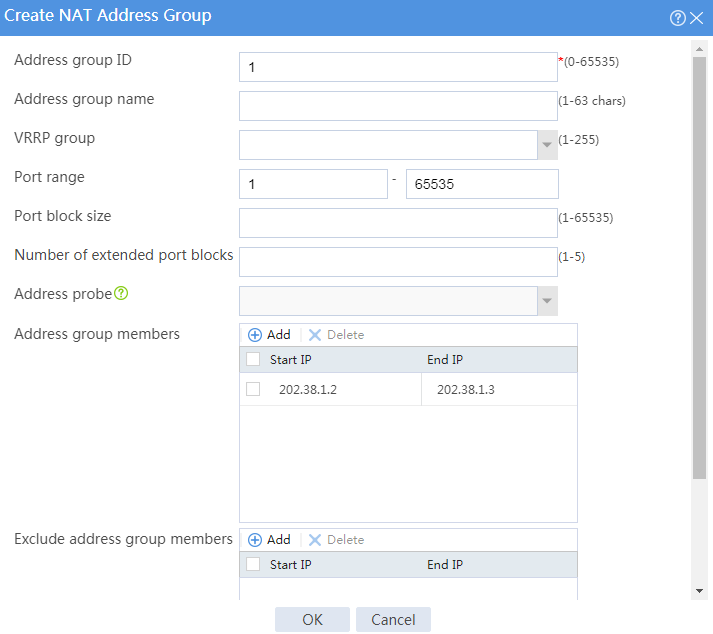
# Click OK.
5. Configure a policy-based NAT rule.
# On the top navigation bar, click Policies.
# From the navigation pane, select NAT > Policy-based NAT.
# Click Create.
# Create a policy-based NAT rule, as shown in Figure 5.
Figure 5 Creating a policy-based NAT rule
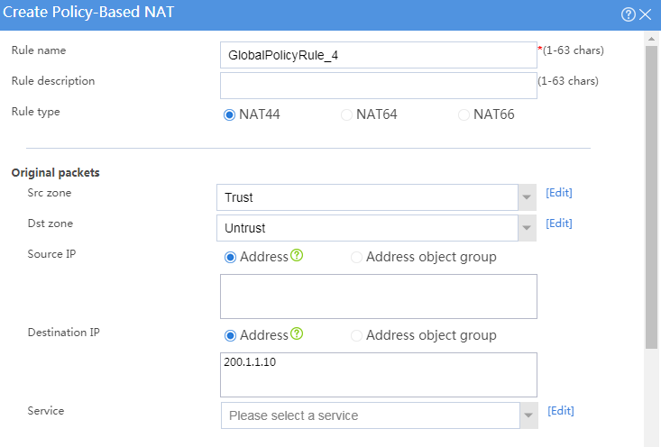
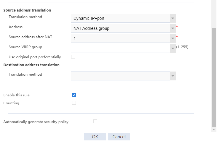
# Click OK.
Verifying the configuration
1. Verify that the host can successfully ping the server on the external network.
C:\Users\abc>ping 200.1.1.10
Pinging host.com [200.1.1.10] with 32 bytes of data:
Reply from 200.1.1.10: bytes=32 time<1ms TTL=253
Reply from 200.1.1.10: bytes=32 time<1ms TTL=253
Reply from 200.1.1.10: bytes=32 time<1ms TTL=253
Reply from 200.1.1.10: bytes=32 time<1ms TTL=253
Ping statistics for 200.1.1.10:
Packets: Sent = 4, Received = 4, Lost = 0 (0% loss),
Approximate round trip times in milli-seconds:
Minimum = 0ms, Maximum = 0ms, Average = 0ms
Network configuration
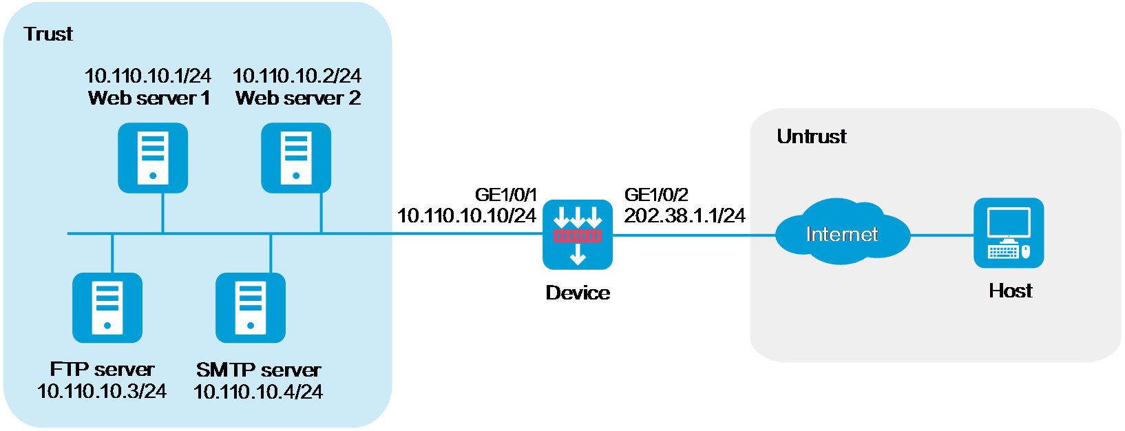
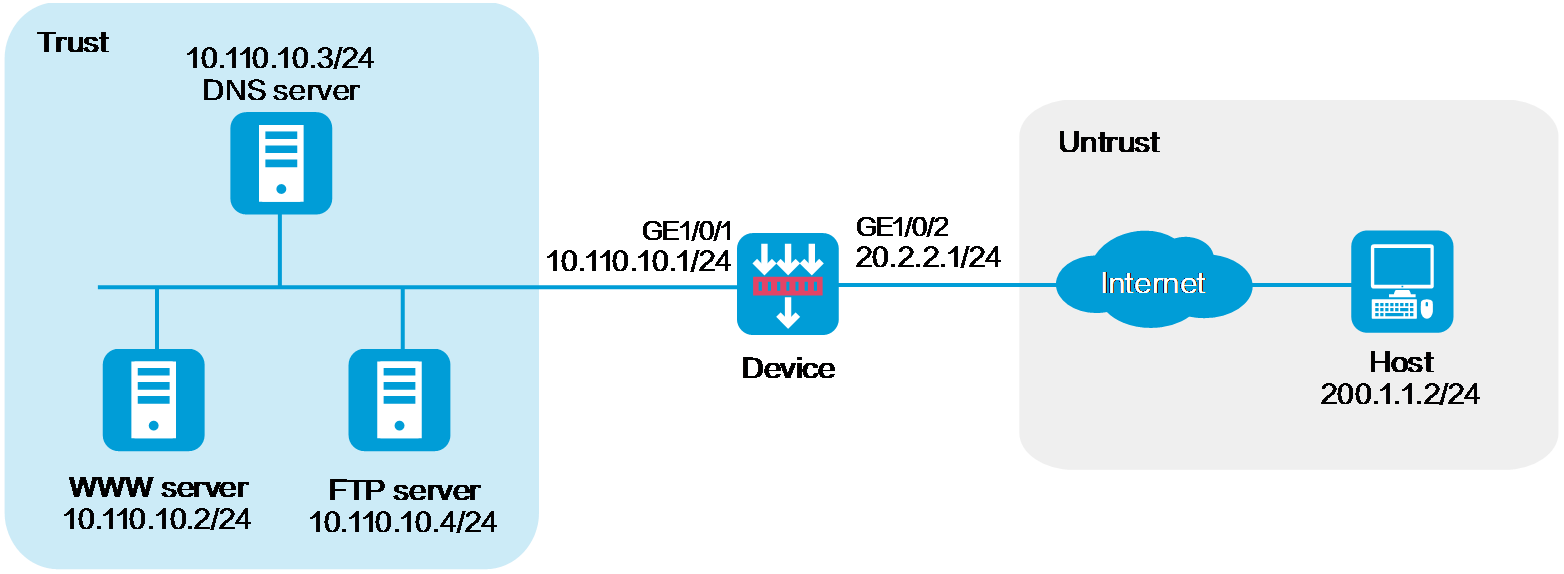
As shown in Figure 6, a company has four servers on the internal network at 10.110.10.0/24 and three public addresses from 202.38.1.1/24 to 202.38.1.3/24. Configure policy-based destination address translation to allow the external host to access the servers by using public address 202.38.1.1 with different ports. The external host uses the following ports to access different servers:
· Uses port 80 to access Web server 1.
· Uses port 8080 to access Web server 2.
· Uses port 21 to access FTP server.
· Uses port 25 to access SMTP server.
Software versions used
This configuration example was created and verified on R8860 of the F1000-AI-55 device.
Procedure
1. Assign IP addresses to interfaces and add the interfaces to security zones.
# On the top navigation bar, click Network.
# From the navigation pane, select Interface Configuration > Interfaces.
# Click the Edit icon for GE 1/0/2.
# In the dialog box that opens, configure the interface:
a. Select the Untrust security zone.
b. On the IPv4 Address tab, enter the IP address and mask of the interface. In this example, enter 202.38.1.1/24.
c. Click OK.
# Add GE 1/0/1 to the Trust security zone and set its IP address to 10.110.10.10/24 in the same way you configure GE 1/0/2.
2. Configure a security policy.
# On the top navigation bar, click Policies.
# From the navigation pane, select Security Policies > Security Policies.
# Click Create and click Create a policy.
# In the dialog box that opens, configure policy parameters as follows:
a. Enter a policy name. In this example, the name is Secpolicy.
b. Select the source zone. In this example, the source zone is Untrust.
c. Select the destination zone. In this example, the destination zone is Trust.
d. Select IPv4 as the type.
e. Select Permit as the action.
f. Specify the IP addresses of the servers as the destination IPv4 addresses. In this example, the addresses are 10.110.10.1, 10.110.10.2, 10.110.10.3, and 10.110.10.4.
g. Click OK.
3. Configure a policy-based NAT rule.
This example configures a policy-based NAT rule for Web server 1.
# On the top navigation bar, click Policies.
# From the navigation pane, select Policy-based NAT.
# Click Create.
# Create a policy-based NAT rule, as shown in Figure 7.
Figure 7 Creating a policy-based NAT rule
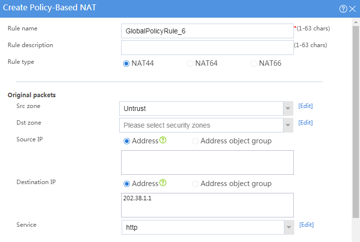
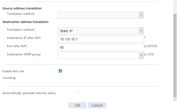
# Click OK.
Verifying the configuration
Verify that the external host can successfully ping the Web server on the internal network.
Network configuration
As shown in Figure 8, Web server at 10.110.10.2/24 in the internal network to provide services for external users. A DNS server at 10.110.10.3/24 is used to resolve the domain name of the Web server. The company has public addresses 202.38.1.2 and 202.38.1.3.
Configure bidirectional translation to allow the external user to access the internal Web server by using the domain name.
Software versions used
This configuration example was created and verified on R8860 of the F1000-AI-55 device.
Procedure
1. Assign IP addresses to interfaces and add the interfaces to security zones.
# On the top navigation bar, click Network.
# From the navigation pane, select Interface Configuration > Interfaces.
# Click the Edit icon for GE 1/0/2.
# In the dialog box that opens, configure the interface:
a. Select the Untrust security zone.
b. On the IPv4 Address tab, enter the IP address and mask of the interface. In this example, enter 20.2.2.1/24.
c. Click OK.
# Add GE 1/0/1 to the Trust security zone and set its IP address to 10.110.10.1/24 in the same way you configure GE 1/0/2.
2. Configure a security policy.
# On the top navigation bar, click Policies.
# From the navigation pane, select Security Policies > Security Policies.
# Click Create and click Create a policy.
# In the dialog box that opens, configure policy parameters as follows:
a. Enter a policy name. In this example, the name is Secpolicy.
b. Select the source zone. In this example, the source zone is Untrust.
c. Select the destination zone. In this example, the destination zone is Trust.
d. Select IPv4 as the type.
e. Select Permit as the action.
f. Specify the IP addresses of the servers as the destination IPv4 addresses. In this example, the addresses are 10.110.10.2, 10.110.10.3, and 10.110.10.4.
g. Click OK.
3. Configure a NAT address group.
# On the top navigation bar, click Objects.
# From the navigation pane, select Object Groups > NAT Address Groups.
# Click Create.
# Create a NAT address group, as shown in Figure 9.
Figure 9 Creating a NAT address group

# Click OK.
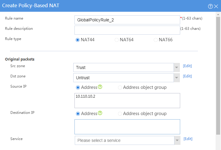
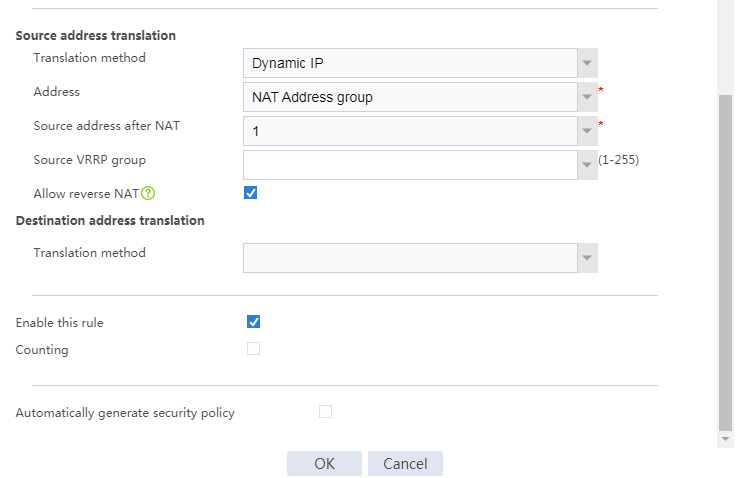
4. Configure policy-based NAT rule 1.
# On the top navigation bar, click Policies.
# From the navigation pane, select Policy-based NAT.
# Click Create.
# Create policy-NAT rule 1 to allow the external user to use public address 202.38.1.2 to access the internal DNS server, as shown in Figure 7.
Figure 10 Creating policy-based NAT rule 1
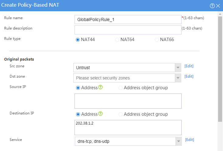

# Click OK.
5. Configure policy-based NAT rule 2.
# On the top navigation bar, click Policies.
# From the navigation pane, select Policy-based NAT.
# Click Create.
# Create policy-NAT rule 2 to translate the source address in a DNS response packet to one address in NAT address group 1, as shown in Figure 7.
Figure 11 Creating policy-based NAT rule 2
# Click OK.
Verifying the configuration
Verify that the external user can successfully ping the Web server on the internal network by using the domain name.