- Table of Contents
-
- 03-Policies
- 01-Security policy
- 02-Attack defense
- 03-Connection limit
- 04-uRPF
- 05-NAT
- 06-AFT
- 07-Application audit
- 08-Bandwidth management
- 09-Load balancing common configuration
- 10-Server load balancing
- 11-Outbound link load balancing
- 12-Inbound link load balancing
- 13-Transparent DNS proxy
- 14-Application proxy
- 15-NetShare control
- 16-Security policy hit analysis
- 17-Security policy redundancy analysis
- 18-Global load balancing
- 19-IP reputation
- 20-NAT66
- 21-Server connection detection
- 22-Security policy optimization
- 23-Server load balancing
- 24-Load balancing common configuration
- Related Documents
-
| Title | Size | Download |
|---|---|---|
| 23-Server load balancing | 277.31 KB |
This help contains the following topics:
¡ Relationship between the main configuration items
· Configure server load balancing
¡ Configure health monitoring (optional)
¡ Configure an SNAT address pool (optional)
¡ Configure a sticky group (optional)
¡ Configure an LB policy (optional)
¡ Configure a connection limit policy (optional)
¡ Configure a parameter profile (optional)
¡ Configure an intelligent probe template (optional)
Introduction
Server load balancing (LB) is a cluster technology that distributes services among multiple servers or firewalls.
Server load balancing is classified into Layer 4 server load balancing and Layer 7 server load balancing.
· Layer 4 server load balancing—Identifies network layer and transport layer information, and is implemented based on streams. It distributes packets in the same stream to the same server. Layer 4 server load balancing cannot distribute Layer 7 services based on contents.
· Layer 7 server load balancing—Identifies network layer, transport layer, and application layer information, and is implemented based on contents. It analyzes packet contents, distributes packets one by one based on the contents, and distributes connections to the specified server according to the predefined policies. Layer 7 server load balancing applies load balancing services to a large scope.
Server load balancing supports IPv4 and IPv6, but Layer 4 server load balancing does not support IPv4-to-IPv6 or IPv6-to-IPv4 translation.
Deployment modes
Server load balancing uses the Network Address Translation (NAT) and indirect deployment modes.
NAT-mode server load balancing
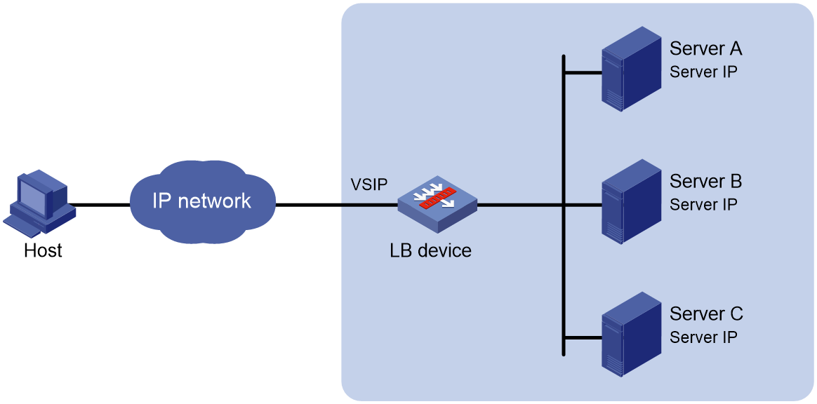
As shown in Figure 1, NAT-mode server load balancing contains the following elements:
· LB device—Distributes different service requests to multiple servers.
· Server—Responds to and processes different service requests.
· VSIP—Virtual service IP address of the cluster, used for users to request services.
· Server IP—IP address of a server, used by the LB device to distribute requests.
Indirect-mode server load balancing
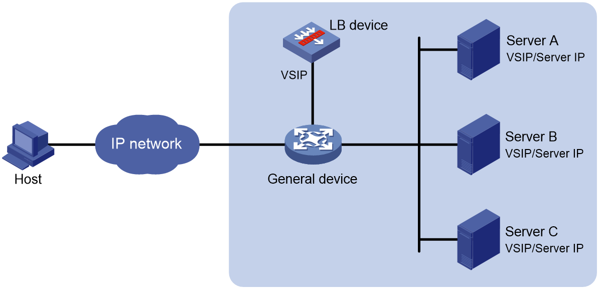
As shown in Figure 2, indirect-mode server load balancing contains the following elements:
· LB device—Distributes different service requests to multiple servers.
· General device—Forwards data according to general forwarding rules.
· Server—Responds to and processes different service requests.
· VSIP—Virtual service IP address of the cluster, used for users to request services.
· Server IP—IP address of a server, used by the LB device to distribute requests.
Indirect-mode server load balancing requires configuring the VSIP on both the LB device and the servers. Because the VSIP on a server cannot be contained in an ARP request and response, you can configure the VSIP on a loopback interface.
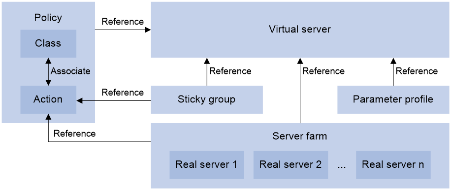
Relationship between the main configuration items
Figure 3 Relationship between the main configuration items
Configure server load balancing
|
|
Before configuring server load balancing, select System > License Config to install a license. |
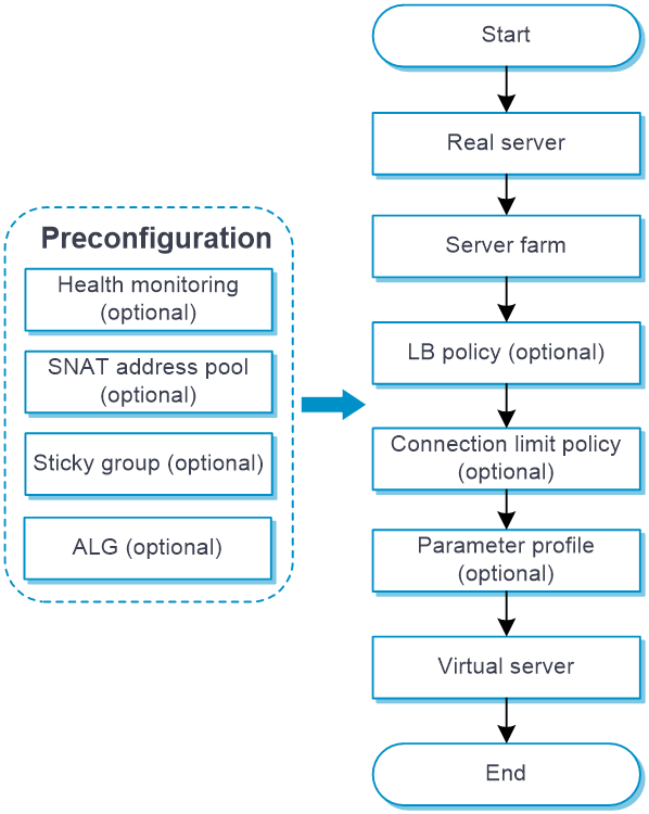
Configure server load balancing as shown in Figure 4.
Figure 4 Server load balancing configuration procedure
Configure health monitoring (optional)
A health monitoring probe template can be used by a real server or server farm.
For more information about configuring health monitoring, see the health monitoring help.
Configure an SNAT address pool (optional)
An SNAT address pool can be used by a server farm.
For more information about configuring an SNAT address pool, see the help for load balancing common configuration.
Configure ALG (optional)
For more information about configuring ALG, see the help for load balancing common configuration.
Configure a server farm
You can add real servers that contain similar content to a server farm to facilitate management. A server farm can be used by a virtual server or an action.
Procedure
1. Select Policies > Load Balancing > Server Load Balancing > Server Farms.
2. Click Create.
3. Create a server farm.
Table 1 Basic configuration items
|
Item |
Description |
|
Server farm name |
Enter a name for the server farm, case insensitive. |
|
Scheduling algorithm |
Select a scheduling algorithm for the server farm. · Round robin—Assigns user requests to real servers based on the weights of real servers. A higher weight indicates more user requests will be assigned. · Random—Randomly assigns user requests to real servers. · Weighted least connections—Always assigns user requests to the real server with the fewest number of weighted active connections (the number of active connections divided by weight). The weight used by this algorithm is configured on the Create Real Server page. · Bandwidth—Distributes user requests to real servers according to the weights and remaining bandwidth of real servers. · Maximum bandwidth—Distributes user requests always to an idle real server that has the largest remaining bandwidth. · Dynamic feedback—Assigns new connections to real servers based on load weight values calculated by using the memory, CPU, and disk usage of the real servers. The less the load, the greater the weight value. A real server with a greater weight value is assigned more connections. · Least time—Assigns new connections to real servers based on load weight values calculated by using the response time of the real servers. The shorter the response time, the greater the weight value. A real server with a greater weight value is assigned more connections. · Source IP address hash—Hashes the source IP address of user requests and distributes user requests to different real servers according to the hash values. · Source IP address CARP hash—Hashes the source IP address of user requests and distributes user requests to different real servers according to the CARP hash values. · Source IP address and port number hash—Hashes the source IP address and port number of user requests and distributes user requests to different real servers according to the hash values. · Source IP address and port number CARP hash—Hashes the source IP address and port number of user requests and distributes user requests to different real servers according to the CARP hash values. · Destination IP address hash—Hashes the destination IP address of user requests and distributes user requests to different real servers according to the hash values. · Destination IP address CARP hash—Hashes the destination IP address of user requests and distributes user requests to different real servers according to the CARP hash values. · HTTP hash—Hashes the content of user requests and distributes user requests to different real servers according to the hash values. · HTTP CARP hash—Hashes the content of user requests and distributes user requests to different real servers according to the CARP hash values. · Weighted least connections (member)—Always assigns user requests to the real server with the fewest number of weighted active connections (the number of active connections divided by weight). The weight used by this algorithm is configured on the Real Server page. · Least time (member)—Always assigns user requests to real servers based on load weight values calculated by using the response time of the real servers. The shorter the response time, the greater the weight value. A real server with a greater weight value is assigned more connections. By default, the source IP address hash algorithm is used. |
|
Offset |
Specify the offset value based on the start of the HTTP content. This parameter is supported only when the scheduling algorithm is HTTP hash or HTTP CARP hash. |
|
Start string |
Specify the regular expression that marks the start of the HTTP content, a string starting from the offset value. The string cannot contain question marks (?). This parameter is supported only when the scheduling algorithm is HTTP hash or HTTP CARP hash. |
|
Length/End string |
· Length specifies the length of the HTTP content. · The end string specifies the regular expression that marks the end of the HTTP content, a string starting from the start string value. The string cannot contain question marks (?). This parameter is supported only when the scheduling algorithm is HTTP hash or HTTP CARP hash. |
|
Priority scheduling |
Specify the upper limit and lower limit of real servers in a server farm that can be scheduled. By default, all real servers with the highest priority in a server farm are scheduled. · If the number of real servers with the highest priority is greater than the configured maximum number, the maximum number applies. · If the number of such real servers is less than the minimum number, real servers with lower priority are selected to meet the minimum number or until no real servers are available. The real server priority can be configured from Policies > Load Balancing > Server Load Balancing > Real Servers. |
|
Real server |
You can add a real server to a server farm in one of the following ways: Create a real server and add it to the server farm. 1. Click Add, and select Create real server. 2. Configure the parameters for the real server (see "Configure a real server"). 3. Click OK. The new real server appears in the real server list. Select an existing real server. 1. Click Add, and select Add existing real server. 2. Select a real server from the list, and configure real server parameters (see "Configure a real server"). 3. Click OK. The real server appears in the real server list. |
|
Probe method |
Specify a probe template used by the server farm to detect the health and availability of its real servers. You can also configure this parameter for a single real server from Policies > Load Balancing > Server Load Balancing > Real Servers. The configuration performed on the Real Server page has higher priority over that performed on the Server Farm page. You can select an existing probe template or create a probe template. A created probe template can be viewed from the Objects > Health Monitoring page. To create a probe template: 1. Click Add. ¡ Template name: Enter a name for the probe template. ¡ Use template's port number for detection: If you select this option, the destination port number specified in the template is used for detection. If you do not select this option, the real server's port number is used for detection. 2. Click OK. The new probe template appears on the Health Monitoring page. |
|
Description |
Enter a description for the server farm. |
Table 2 Advanced configuration items
|
Item |
Description |
|
Success criteria |
Specify the health monitoring success criteria for the real server. · All probes succeed: Health monitoring succeeds only when all the specified health monitoring methods succeed. · At least n probes succeed: Health monitoring succeeds when a minimum of the specified number of health monitoring methods succeed. When the specified number of health monitoring methods is greater than the number of health monitoring methods on the device, health monitoring succeeds if all health monitoring methods succeed. |
|
SNAT pool |
Select an existing SNAT pool or create an SNAT pool for the server farm. A created SNAT pool can be viewed from Policies > Load Balancing > Common Configuration > SNAT Address Pools. |
|
NAT |
Disable NAT for the server farm in indirect-mode NAT configuration, or enable NAT for the server farm in NAT-mode configuration. |
|
RST packet monitoring |
Select an existing RST probe template or create an RST probe template for the server farm. A created RST probe template can be viewed from Policies > Load Balancing > Server Load Balancing > Probe Templates. |
|
Zero-window packet monitoring |
Select an existing zero-window probe template or create a zero-window probe template for the server farm. A created zero-window probe template can be viewed from Policies > Load Balancing > Server Load Balancing > Probe Templates. |
|
HTTP passive probe |
Select an existing HTTP passive probe template or create an HTTP passive probe template for the server farm. A created HTTP passive probe template can be viewed from Policies > Load Balancing > Server Load Balancing > Probe Templates. |
|
Auto recovery |
Enable or disable auto recovery. This function enables automatic recovery for real servers shut down by RST or zero-window probe templates. If health monitoring is not configured, a real server is recovered to the unknown state. If health monitoring is configured and succeeds, a real server is recovered to the available state. If health monitoring fails, a real server is recovered to the health-monitoring-failed state. This function is available only when an HTTP passive, RST, or zero-window probe template is specified for a server farm. |
|
Recovery time |
Enter the auto recovery time. The value 0 means that real servers cannot automatically recover. This parameter is available only when auto recovery is enabled. |
|
Fault processing method |
Specify the fault processing method for the real server. · Keep existing connections—Keeps the connection with the failed real server. Keeping or terminating the connection depends on the timeout mechanism of the protocol. · Redirect connections—Redirects the connection to another available real server in the server farm. · Terminate existing connections—Terminates the connection with the failed real server by sending RST packets (for TCP packets) or ICMP unreachable packets (for other types of packets). |
|
Slow online |
The real servers newly added to a server farm might not be able to immediately process large numbers of services assigned by the LB device. To resolve this issue, enable the slow online feature for the server farm. The feature uses the standby timer and ramp-up timer. When the real servers are brought online, the LB device does not assign any services to the real servers until the standby timer expires. When the standby timer expires, the ramp-up timer starts. During the ramp-up time, the LB device increases the service amount according to the processing capability of the real servers, until the ramp-up timer expires. · Standby time: The value range is 0 to 600 seconds. · Ramp-up time: The value range is 3 to 600 seconds. |
|
Action upon busyness |
Specify the action to take when the server farm is busy. A server farm is considered busy when all its real servers are busy. You can configure one of the following actions: · Schedule—Forcibly assigns client requests to all real servers in the server farm. · Queue and wait—Stops assigning client requests to a server farm and assigns new client requests to a wait queue. ¡ Queue length: New client requests will be dropped when the queue length exceeds the configured length. ¡ Timeout time: Client requests already in the queue will be aged out when the configured timeout time expires. · Render scheduling failed—Stops assigning client requests to a server farm. If the LB policy for the server farm contains the action of matching the next rule, the device compares client requests with the next rule. Otherwise, the device drops the client requests. The device determines whether a real server is busy based on the following factors: · Maximum number of connections. · Maximum number of connections per second. · Maximum number of HTTP requests per second. · Maximum bandwidth, maximum inbound bandwidth, and maximum outbound bandwidth. · SNMP-DCA probe result. |
|
Availability criteria |
Set the criteria (lower percentage and upper percentage) to determine whether a server farm is available. This helps implement traffic switchover between the master and backup server farms. · Lower percentage—When the number of available real servers to the total number of real servers in the primary server farm is smaller than the lower percentage, traffic is switched to the backup server farm. · Upper percentage—When the number of available real servers to the total number of real servers in the primary server farm is greater than the upper percentage, traffic is switched back to the master server farm. |
4. Click OK. The new server farm appears on the Server Farm page.
Configure a real server
A real server is an entity on the LB device to process user services. A real server can belong to multiple server farms. A server farm can have multiple real servers.
Procedure
1. Select Policies > Load Balancing > Server Load Balancing > Real Servers.
2. Click Create.
3. Create a real server.
Table 3 Basic configuration items
|
Item |
Description |
|
Real server name |
Enter a name for the real server, case insensitive. |
|
IPv4 address |
Specify an IPv4 address for the real server. The IPv4 address cannot be a loopback address, multicast address, broadcast address, or an address in the format of 0.X.X.X. |
|
IPv6 address |
Specify an IPv6 address for the real server. The IPv6 address cannot be a loopback address, multicast address, link-local address, or all-zero address. |
|
Port number |
Specify the port number for the real server. If the port number is 0, packets use their respective port numbers. |
|
VPN instance |
Specify a VPN instance for the real server. |
|
VPN instance inheritance |
Enable or disable VPN instance inheritance. When VPN instance inheritance is enabled, a real server without a VPN instance specified inherits the VPN instance of its virtual server. |
|
Real server feature |
Enable or disable the real server feature. |
|
Description |
Enter a description for the real server. |
Table 4 Advanced configuration items
|
Item |
Description |
|
Weight |
Enter the weight for the real server. For the weighted round robin algorithm and weighted least connections algorithm, a greater value means a higher priority to be selected. |
|
Priority |
Enter a priority for the real server in the server farm. A greater value means a higher priority to be selected. If the number of real servers with the highest priority is smaller than the configured minimum number, real servers with lower priority are selected to meet the minimum number. You can configure the maximum number and minimum number from Policies > Load Balancing > Server Load Balancing > Server Farms. |
|
Server farm |
Select an existing server farm or create a server farm for the real server. A created server farm can be viewed from Policies > Load Balancing > Server Load Balancing > Server Farms. |
|
Probe-Probe method |
Specify a probe template used by the real server to detect the health and availability. You can also configure this parameter for a server farm from Policies > Load Balancing > Server Load Balancing > Server Farms. The configuration performed on the Real Server page has higher priority over that performed on the Server Farm page. You can select an existing probe template or create a probe template. A created probe template can be viewed from the Objects > Health Monitoring page. To create a probe template: 1. Click Add. ¡ Template name: Enter a name for the probe template. ¡ Use template's port number for detection: If you select this option, the destination port number specified in the template is used for detection. If you do not select this option, the real server's port number is used for detection. 2. Click OK. The new probe template appears on the Health Monitoring page. |
|
Probe-Success criteria |
Specify the health monitoring success criteria for the real server. · All probes succeed: Health monitoring succeeds only when all the specified health monitoring methods succeed. · At least n probes succeed: Health monitoring succeeds when a minimum of the specified number of health monitoring methods succeed. When the specified number of health monitoring methods is greater than the number of health monitoring methods on the device, health monitoring succeeds if all health monitoring methods succeed. |
|
QoS-Max connections |
Specify the maximum number of connections for the real server. 0 means not limited. |
|
QoS-Max connections per second |
Specify the maximum number of connections per second for the real server. 0 means not limited. |
|
QoS-HTTP requests per second |
Specify the maximum number of HTTP requests per second for the real server. 0 means not limited. |
|
QoS-Total max bandwidth |
Specify the maximum bandwidth for the real server. 0 means not limited. |
|
QoS-Max inbound bandwidth |
Specify the maximum inbound bandwidth for the real server. 0 means not limited. |
|
QoS-Max outbound bandwidth |
Specify the maximum outbound bandwidth for the real server. 0 means not limited. |
4. Click OK. The new real server appears on the Real Server page.
Configure a sticky group (optional)
A sticky group can be used by a virtual server or an action.
For more information about configuring a sticky group, see the help for load balancing common configuration.
Configure an LB policy (optional)
An LB policy associates a class with an action to guide packet forwarding. In an LB policy, you can configure an action for packets matching the specified class, and configure the default action for packets matching no class.
You can specify multiple classes for an LB policy. Packets match the classes in the order the classes are configured. If a class is matched, the specified action is taken. If no class is matched, the default action is taken.
An LB policy can be used by a virtual server.
Configure a class
1. Select Policies > Load Balancing > Server Load Balancing > Advanced Policies > Class.
2. Click Create.
3. Create a class.
Table 5 Class configuration items
|
Item |
Description |
|
Class name |
Enter a name for the class, case insensitive. |
|
Type |
Specify the type for the class. · Generic: Applies to Layer 4 server load balancing. · HTTP: Applies to Layer 7 server load balancing. · RADIUS: Applies to Layer 7 server load balancing. · MySQL: Applies to Layer 7 server load balancing. |
|
Match type |
Specify the match type for the class. · Match any: Requires matching any rule of the LB class. · Match all: Requires matching all rules of the LB class. |
|
Match rule |
A class classifies packets by comparing packets with specific rules. Matching packets are further processed by actions. You can create a maximum of 65535 rules for a class. 1. Click Create to create a match rule. ¡ Rule ID: Specify the rule ID. Rules are matched in ascending order of rule IDs. ¡ Type: Specify the rule type. The rule types include source IPv4 address, source IPv6 address, class, IPv4 ACL, IPv6 ACL, cookie, HTTP header, method, URL, content, user, RADIUS attribute, input interface, ISP, TCP payload, and MySQL. ¡ IPv4 address: Specify an IPv4 address. This parameter is available only when the rule type is source IPv4 address. ¡ Mask length: Specify a mask length. This parameter is available only when the rule type is source IPv4 address. ¡ IPv6 address: Specify an IPv6 address. This parameter is available only when the rule type is source IPv6 address. ¡ Prefix length: Specify a prefix length. This parameter is available only when the rule type is source IPv6 address. ¡ Class: Specify a class. This parameter is available only when the rule type is class. ¡ ACL: Specify an ACL. You can select an existing ACL or create an ACL. A created IPv4 ACL can be viewed from Objects > ACLs > IPv4 ACLs. A created IPv6 ACL can be viewed from Objects > ACLs > IPv6 ACLs. This parameter is available only when the rule type is IPv4 ACL or IPv6 ACL. ¡ Cookie name: Specify the cookie name for HTTP packets. The cookie name is a case-sensitive string excluding spaces, horizontal tabs, ASCII characters smaller than or equal to 31, ASCII characters greater than or equal to 127, or the following characters: ( ) < > @ , ; : \ " / [ ] ? = { }. This parameter is available only when the rule type is cookie. ¡ Cookie value: Specify the cookie value regular expression. The string cannot contain question marks (?). This parameter is available only when the rule type is cookie. ¡ Header name: Specify the header name for HTTP packets. The header name is a case-insensitive string excluding spaces, horizontal tabs, ASCII characters smaller than or equal to 31, ASCII characters greater than or equal to 127, or the following characters: ( ) < > @ , ; : \ " / [ ] ? = { }. This parameter is available only when the rule type is HTTP header. ¡ Header value: Specify the header value regular expression. The string cannot contain question marks (?). This parameter is available only when the rule type is HTTP header. ¡ Extension type: The extension type can be Predefined or Custom. This parameter is available only when the rule type is method. ¡ Method: The predefined methods include GET, CONNECT, DELETE, HEAD, OPTIONS, POST, PUT, and TRACE. The custom method is a case-sensitive string excluding spaces, horizontal tabs, ASCII characters smaller than or equal to 31, ASCII characters greater than or equal to 127, or the following characters: ( ) < > @ , ; : \ " / [ ] ? = { }. This parameter is available only when the rule type is method. ¡ URL: Specify the URL regular expression. The string cannot contain question marks (?). This parameter is available only when the rule type is URL. ¡ Content offset: Specify the offset value of the HTTP entity based on the start of the HTTP packet. This parameter is available only when the rule type is content. ¡ Content value: Specify the HTTP entity regular expression. The string cannot contain question marks (?). This parameter is available only when the rule type is content. ¡ User: Select an existing user or user group in an identity domain, or create a user or user group. This parameter is available only when the rule type is user. ¡ Attribute type: Enter an attribute type value. This parameter is available only when the rule type is RADIUS attribute. ¡ Attribute value: Specify the RADIUS attribute regular expression. This parameter is available only when the rule type is RADIUS attribute. ¡ Input interface: Specify an input interface. This parameter is available only when the rule type is input interface. ¡ ISP: Select an existing ISP, or create an ISP. A created ISP can be viewed from Policies > Load Balancing > Common Configuration > ISP. This parameter is available only when the rule type is ISP. ¡ TCP payload: Enter a regular expression used to match TCP payloads. This parameter is available only when the rule type is TCP flow. ¡ Case insensitivity: Enable case insensitivity for matching. This parameter is available only when the rule type is TCP payload or MySQL. ¡ Negate the match rule: If this option is not selected, an LB action is taken when TCP packets match the regular expression. If this option is selected, an LB action is taken when TCP packets do not match the regular expression. This parameter is available only when the rule type is TCP payload or MySQL. ¡ Regular expression: Enter a regular expression used to match MySQL statements. This parameter is available only when the rule type is MySQL. 2. Click OK. |
|
Description |
Enter a description for the class. |
4. Click OK. The new class appears on the Class page.
Configure an action
1. Select Policies > Load Balancing > Server Load Balancing > Advanced Policies > Action.
2. Click Create.
3. Create an action.
Table 6 Basic configuration items
|
Item |
Description |
|
Action name |
Enter a name for the action, case insensitive. |
|
Type |
Specify an action type. · Generic · HTTP · HTTP redirection · RADIUS |
|
Forwarding mode |
Specify a forwarding mode: · Load balance · Drop · Forward (supported by generic type and RADIUS type only) · Respond by using a file (supported by HTTP type only) |
|
Uncompressed file |
If the URL path in a client request matches the specified URL path, the device responds to the request by using an uncompressed file. 1. Click Create to create an uncompressed response file. ¡ URL path: Specifies the URL path used to match HTTP requests, a case-sensitive string. The specified URL path must start with a forward slash (/). ¡ Uncompressed file: Specifies an uncompressed file by its absolute path plus a file name, which is case insensitive, for example, flash:/file.html. Only one uncompressed file can be used for a URL, and one uncompressed file can be used for multiple URLs. 2. Click OK. This parameter is available only when the forwarding mode is Respond by using a file. |
|
Compressed file |
If the URL path in a client request matches the specified working path plus a relative path in the zip file, the device responds to the request by using the file in the zip file. For example, if you configure the working path as /index and compressed file as flash:/za/zb/test.zip, and a relative path /css/col.css exists in test.zip, the matching URL is /index/css/col.css and the response file is col.css. · Working path: Specify a working path plus a relative path in the zip file to match the URL in HTTP requests, a case-sensitive string. The working path must start with a forward slash. · Compressed file: Specify a compressed file by its absolute path plus a file name, which is case insensitive. The file must be a zip file, for example, flash:/file.zip. This parameter is available only when the forwarding mode is Respond by using a file. |
|
Fallback action |
Specify a fallback action. · Match next rule: Matches the next rule upon failure to find an available real server. · Respond by using another file: Responds to client requests with the specified default response file upon failure to find an available real server. ¡ Default response file: Specifies an uncompressed file by its absolute path plus a file name, which is case insensitive, for example, flash:/file.html. · Fin close: Sends FIN packets to close the TCP connection. · Rst close: Sends RST packets to close the TCP connection. This parameter is available only when the forwarding mode is Load balance. |
|
Action taken upon failure to find the response file |
Specify an action taken upon failure to find the response file. · Match next rule: Matches the next rule upon failure to find a response file. · Respond by using a file: Responds to client requests with the specified default response file upon failure to find a response file. ¡ Default response file: Specifies an uncompressed file by its absolute path plus a file name, which is case insensitive, for example, flash:/file.html. · Fin close: Sends FIN packets to close the TCP connection. · Rst close: Sends RST packets to close the TCP connection. This parameter is available only when the forwarding mode is Respond by using a file. |
|
TCP connection close mode |
Specify a TCP connection close mode. · By sending FIN: Sends FIN packets to close the TCP connection. · By sending RST: Sends RST packets to close the TCP connection. This parameter is available only when the forwarding mode is Drop. |
|
ToS |
Set the ToS field value of IP packets sent to the server. |
|
Description |
Enter a description for the action. |
|
Server farms-Primary server farm |
When the primary server farm is available (contains real servers), packets are forwarded through the primary server farm. When the primary server farm is not available, packets are forwarded through the backup server farm. You can select an existing server farm or create a server farm. A created server farm can be viewed from Policies > Load Balancing > Server Load Balancing > Server Farms. This parameter is available only when the forwarding mode is Load balance. |
|
Server farms-Backup server farm |
Select an existing server farm or create a server farm. A created server farm can be viewed from Policies > Load Balancing > Server Load Balancing > Server Farms. This parameter is available only when the forwarding mode is Load balance. |
|
Server farms-Sticky group |
Select an existing sticky group or create a sticky group. A created sticky group can be viewed from Policies > Load Balancing > Common Configuration > Sticky Groups. This parameter is available only when the forwarding mode is Load balance. |
|
HTTP redirection configuration-Redirection URL |
This setting redirects all HTTP request packets matching an action to the specified URL. Specify a redirection URL, a case-sensitive string. You can also specify the question mark (?) or the following character strings as the redirection URL: · %h: Specifies the host name in the client request packet. · %p: Specifies the URL in the client request packet. · %%: Specifies the percentage sign (%). This parameter is available only when the action type is HTTP redirection. |
|
HTTP redirection configuration -Redirection mode |
Specify a redirection mode. · Temporary · Permanent This parameter is available only when the action type is HTTP redirection. |
Table 7 Advanced configuration items (available only when the action type is HTTP and the forwarding mode is Load balance or Respond by using a file)
|
Item |
Description |
|
Insert X-Forwarded-For |
Insert the X-Forwarded-For header. |
|
Response content rewrite-Content before rewrite |
Specify the HTTP packet content to be rewritten. |
|
Response content rewrite-Content after rewrite |
Specify the HTTP packet content after rewrite. · %is: Source IPv4 or IPv6 address. · %ps: Source port number. · %id: Destination IPv4 or IPv6 address. · %pd: Destination port number. · %%: Percentage sign (%). · %[1-9] : Header value enclosed in parenthesis. |
|
Header deletion |
1. Click Create. ¡ Direction: Specify the direction, which can be Both, Request, or Response. ¡ Header name: Specify the header name, which is case insensitive and can be predefined or customized. It cannot contain spaces, horizontal tabs, ASCII characters less than or equal to 31, ASCII characters greater than or equal to 127, or the following characters: ( ) < > @ , ; : \ " / [ ] ? = { }. 2. Click OK. |
|
Header insertion |
1. Click Create. ¡ Direction: Specify the direction of HTTP packets, which can be Both, Request, or Response. ¡ Header name: Specify the header name, which is case insensitive and can be predefined or customized. It cannot contain spaces, horizontal tabs, ASCII characters less than or equal to 31, ASCII characters greater than or equal to 127, or the following characters: ( ) < > @ , ; : \ " / [ ] ? = { }. ¡ Header value: Specify the header content to be inserted to the HTTP packet. The string cannot contain question marks (?). You can also specify the following replacement strings: %is: Source IP address in HTTP requests. %ps: Source port number in HTTP requests. %id: Destination IP address in HTTP requests. %pd: Destination port number in HTTP requests. %sps: Source IP address in HTTP responses. %spd: Source port number in HTTP responses. %sis: Destination IP address in HTTP responses. %sid: Destination port number in HTTP responses. %{x509v}: Certificate version. %{x509snum}: Certificate serial number. %{x509sigalgo}: Certificate signature algorithm. %{x509issuer}: Certificate issuer. %{x509before}: Certificate effective time. %{x509after}: Certificate expiration time. %{x509sub}: Certificate subject. %{x509spktype}: Public key type for the certificate subject. %{x509spk}: Public key for the certificate subject. %{x509spkRSA}: Length of the RSA public key for the certificate subject (available only for an RSA public key). %{x509hash}: MD5 hash value of the client certificate. %{dncn}: Issuee. %{dne}: Email. %{dno}: Company/Organization. %{dnou}: Department. %{dnc}: Country. %{dns}: State/Province. %{dnl}: City. ¡ Encoding method: Specify an encoding method for replacement strings, which can be Not encoded, URL, or Base64. URL encoding encodes only spaces and the following special characters in replacement strings ; / ? : @ & = + $ | { } , \ ^ [ ] ` < > # %. Base64 encoding encodes entire replacement strings. 2. Click OK. |
|
Header rewrite |
1. Click Create. ¡ Direction: Specify the direction of HTTP packets, which can be Both, Request, or Response. ¡ Header name: Specify the header name, which is case insensitive and can be predefined or customized. It cannot contain spaces, horizontal tabs, ASCII characters less than or equal to 31, ASCII characters greater than or equal to 127, or the following characters: ( ) < > @ , ; : \ " / [ ] ? = { }. ¡ Header value: Specify the header content after rewrite. The string cannot contain question marks (?). You can also specify the following replacement strings: %is: Source IP address in HTTP requests. %ps: Source port number in HTTP requests. %id: Destination IP address in HTTP requests. %pd: Destination port number in HTTP requests. %sps: Source IP address in HTTP responses. %spd: Source port number in HTTP responses. %sis: Destination IP address in HTTP responses. %sid: Destination port number in HTTP responses. %1-9: Specified string used for replacement. A maximum of nine items are supported. %{x509v}: Certificate version. %{x509snum}: Certificate serial number. %{x509sigalgo}: Certificate signature algorithm. %{x509issuer}: Certificate issuer. %{x509before}: Certificate effective time. %{x509after}: Certificate expiration time. %{x509sub}: Certificate subject. %{x509spktype}: Public key type for the certificate subject. %{x509spk}: Public key for the certificate subject. %{x509spkRSA}: Length of the RSA public key for the certificate subject (available only for an RSA public key). %{x509hash}: MD5 hash value of the client certificate. %{dncn}: Issuee. %{dne}: Email. %{dno}: Company/Organization. %{dnou}: Department. %{dnc}: Country. %{dns}: State/Province. %{dnl}: City. ¡ Encoding method: Specify an encoding method for replacement strings, which can be Not encoded, URL, or Base64. URL encoding encodes only spaces and the following special characters in replacement strings ; / ? : @ & = + $ | { } , \ ^ [ ] ` < > # %. Base64 encoding encodes entire replacement strings. 2. Click OK. |
|
URL rewrite |
1. Click Create. ¡ URL to be rewritten: The URL content cannot contain question marks (?). ¡ URL after rewrite: Specify the URL content after rewrite. You can also specify the following replacement strings: %is: Source IP address in HTTP requests. %ps: Source port number in HTTP requests. %id: Destination IP address in HTTP requests. %pd: Destination port number in HTTP requests. %sps: Source IP address in HTTP responses. %spd: Source port number in HTTP responses. %sis: Destination IP address in HTTP responses. %sid: Destination port number in HTTP responses. %1-9: Specified string used for replacement. A maximum of nine items are supported. %{x509v}: Certificate version. %{x509snum}: Certificate serial number. %{x509sigalgo}: Certificate signature algorithm. %{x509issuer}: Certificate issuer. %{x509before}: Certificate effective time. %{x509after}: Certificate expiration time. %{x509sub}: Certificate subject. %{x509spktype}: Public key type for the certificate subject. %{x509spk}: Public key for the certificate subject. %{x509spkRSA}: Length of the RSA public key for the certificate subject (available only for an RSA public key). %{x509hash}: MD5 hash value of the client certificate. %{dncn}: Issuee. %{dne}: Email. %{dno}: Company/Organization. %{dnou}: Department. %{dnc}: Country. %{dns}: State/Province. %{dnl}: City. ¡ Encoding method: Specify an encoding method for replacement strings, which can be Not encoded, URL, or Base64. URL encoding encodes only spaces and the following special characters in replacement strings ; / ? : @ & = + $ | { } , \ ^ [ ] ` < > # %. Base64 encoding encodes entire replacement strings. 2. Click OK. |
|
SSL security-SSL client policy |
Select an existing SSL client policy or create an SSL client policy. A created SSL client policy can be viewed from Objects > SSL > SSL Client Policies. |
|
SSL security-SSL redirection URL list |
1. Click Create. ¡ URL: Specify the Location header URL regular expression. ¡ HTTP port: Specify the HTTP port number to be rewritten. ¡ SSL port: Specify the SSL port number after rewrite. 2. Click OK. |
4. Click OK. The new action appears on the Action page.
Configure an LB policy
1. Select Policies > Load Balancing > Server Load Balancing > Advanced Policies > Load Balancing Policy.
2. Click Create.
3. Create an LB policy.
Table 8 LB policy configuration items
|
Item |
Description |
|
Name |
Enter a name for the LB policy, case insensitive. |
|
Type |
Specify the type for the LB policy. · Generic: Applies to Layer 4 server load balancing. · HTTP: Applies to Layer 7 server load balancing. · RADIUS: Applies to Layer 7 server load balancing. · MySQL: Applies to Layer 7 server load balancing. |
|
Default action |
Specify a generic action for a generic LB policy, or specify any type of action for an HTTP LB policy. You can select an existing action or create an action. A created action can be viewed from Policies > Load Balancing > Server Load Balancing > Advanced Policies > Action. |
|
Rule |
Specify an action for packets matching the specified class. 1. Click Create. ¡ Class: Select an existing class or create a class. A created class can be viewed from Policies > Load Balancing > Server Load Balancing > Advanced Policies > Class. ¡ Action: Select an existing action or create an action. A created action can be viewed from Policies > Load Balancing > Server Load Balancing > Advanced Policies > Action. ¡ Insert before: Inserts the target class before a class. 2. Click OK. |
|
Description |
Enter a description for the LB policy. |
4. Click OK. The new LB policy appears on the Load Balancing Policy page.
Configure a connection limit policy (optional)
A connection limit policy can have multiple rules. Each rule specifies a range of users and the limit to the user connections. A connection limit policy applies only to the user connections matching a rule. When the number of connections for a certain type reaches the upper limit, the device does not accept new connection requests of that type. It accepts new connection requests only when the number of connections drops below the lower limit.
The user ranges in the rules are set by using ACLs.
Procedure
1. Select Policies > Load Balancing > Server Load Balancing > Advanced Policies > Connection Limit Policy.
2. Click Create.
3. Create a connection limit policy.
Table 9 Connection limit policy configuration items
|
Item |
Description |
|
Name |
Enter a name for the connection limit policy, case insensitive. |
|
Limit rule |
Create a rule. 1. Click Create. ¡ Rule ID: Specify an ID for the connection limit rule. ¡ Type: Specify a connection limit rule type, which can be IPv4 ACL or IPv6 ACL. ¡ ACL: Specify an ACL. You can select an existing ACL or create an ACL. A created IPv4 ACL can be viewed from Objects > ACLs > IPv4 ACLs. A created IPv6 ACL can be viewed from Objects > ACLs > IPv6 ACLs. ¡ Limit by: Select source IP address, destination IP address, or service. Source IP address limits user connections by source IP address. Destination IP address limits user connections by destination IP address. Service limits user connections by service. Services are classified by transport layer protocol and service port number. ¡ Connection limits-Upper limit: Specify the upper limit of connections. When the number of connections in a specified range or for a certain type reaches the upper limit, the device does not accept new connection requests. ¡ Connection limits–Lower limit: Specify the lower limit of connections. The lower limit must be equal to or smaller than the upper limit. The device accepts new connection requests only when the number of connections drops below the lower limit. 2. Click OK. |
|
Description |
Enter a description for the connection limit policy. |
4. Click OK. The new connection limit policy appears on the Connection Limit Policy page.
Configure a parameter profile (optional)
You can configure advanced parameters through a parameter profile. The virtual server references the parameter profile to analyze, process, and optimize service traffic.
Procedure
1. Select Policies > Load Balancing > Server Load Balancing > Parameter Profiles.
2. Click Create.
3. Create a parameter profile.
Table 10 Parameter profile configuration items
|
Item |
Description |
|
Parameter profile name |
Enter a name for the parameter profile, case insensitive. |
|
Type |
Specify the type for the parameter profile. · IP: Applies to Layer 4 server load balancing. For more information about IP parameter configuration, see Table 11. · TCP: Applies to Layer 7 server load balancing. For more information about TCP parameter configuration, see Table 12. · HTTP: Applies to Layer 7 server load balancing. For more information about HTTP parameter configuration, see Table 13. · HTTP-Compress: Applies to Layer 7 server load balancing. For more information about HTTP compression parameter configuration, see Table 14. · HTTP-Statistics: Applies to Layer 7 server load balancing. For more information about HTTP statistics parameter configuration, see Table 15. · OneConnect: Applies to Layer 7 server load balancing. For more information about OneConnect parameter configuration, see Table 16. · TCP-Application: Applies to Layer 7 server load balancing. For more information about TCP application parameter configuration, see Table 17. · MySQL: Applies to Layer 7 server load balancing. For more information about MySQL application parameter configuration, see Table 18. |
|
Description |
Enter a description for the parameter profile. |
Table 11 IP parameter configuration items
|
Item |
Description |
|
ToS sent to client |
Set the ToS field value of IP packets sent to the client. |
Table 12 TCP parameter configuration items
|
Item |
Description |
|
Max local window size |
Configure the maximum local window size for TCP connections. |
|
Option operation list |
This feature enables the LB device to insert the client's actual IP address into the specified option in headers of TCP packets sent to the server or remove the specified option. 1. To create an option operation, click Create. ¡ Insert: Inserts the client's actual IP address into the specified option in headers of TCP packets sent to the server. ¡ Remove: Removes the specified option from headers of TCP packets sent to the server. ¡ Option number: Number of the option to be operated. 2. Click OK. The new option operation appears in the Option operation list. |
|
Action on MSS-exceeded packets |
Specify the action to take on the segments that exceed the MSS in the HTTP requests sent by the client. · Permit: Allows the segments to exceed the MSS. · Drop: Discards the segments that exceed the MSS. |
|
TCP MSS |
Specify the MSS for the LB device. |
|
TIME-WAIT timeout time |
Set the TIME_WAIT state timeout time for TCP connections. A TCP connection is released slowly after it is disconnected, because the TIME_WAIT timer of TCP is long. You can adjust the TIME_WAIT state timeout time. This parameter takes effect only when the TCP parameter profile is used by an HTTP or HTTPS virtual server. |
|
SYN timeout time |
Set the SYN packet timeout time for TCP connections. If no SYN-ACK packet is received when the timer expires, the TCP connection is closed. This parameter takes effect only when the TCP parameter profile is used by an HTTP or HTTPS virtual server. |
|
Keepalive timeout time |
Set the TCP keepalive packet sending interval for an idle TCP connection. This parameter takes effect only when the TCP parameter profile is used by an HTTP or HTTPS virtual server. |
|
Keepalive retransmission interval |
Set the TCP keepalive packet retransmission interval. This parameter takes effect only when the TCP parameter profile is used by an HTTP or HTTPS virtual server. |
|
Keepalive retransmission times |
Set the TCP keepalive packet retransmission times. This parameter takes effect only when the TCP parameter profile is used by an HTTP or HTTPS virtual server. |
|
FIN-WAIT-1 timeout time |
Set the FIN-WAIT-1 state timeout timer for TCP connections. This parameter takes effect only when the TCP parameter profile is used by an HTTP or HTTPS virtual server. |
|
FIN-WAIT-2 timeout time |
Set the FIN-WAIT-2 state timeout timer for TCP connections. This parameter takes effect only when the TCP parameter profile is used by an HTTP or HTTPS virtual server. |
Table 13 HTTP parameter configuration items
|
Item |
Description |
|
Max header parse length |
Set the maximum length of HTTP headers that can be parsed. |
|
Max content parse length |
Set the maximum length of the HTTP entities that can be parsed. |
|
Secondary cookie delimiter |
Specify the delimiter that separates secondary cookies in URLs, including ! " # ; < > ? [ \ ] ^ ` | : @ & $ + * ' ( ) , /. |
|
Secondary cookie start delimiter |
Specify the start delimiter for secondary cookies in URLs, including ! " # ; < > ? [ \ ] ^ ` |. |
|
Action on max-header-length exceeded packets |
Specify the action to take on the HTTP requests when their packet headers exceed the maximum length. · Permit: Allows the HTTP requests to pass. · Drop: Discards the HTTP requests. When the HTTP packet header length exceeds the processing capability of load balancing, the drop action applies. |
|
Per-packet load balancing |
Enable or disable per-packet load balancing for HTTP requests. |
|
Connection reuse |
Enable or disable connection reuse between the LB device and the server. Connection reuse allows the LB device to establish connections to the server that can be reused by clients. Because multiple clients can use the same connection, the number of connections between the clients and the server is reduced. |
|
Case sensitivity |
Enable or disable case sensitivity for matching character strings. This setting affects the following content: · HTTP header value, HTTP cookie name and value, and URL for matching classes. · Header value, URL, and key value used for generating sticky entries for the HTTP header sticky method. · Cookie name and value and key value used for generating sticky entries for the cookie get sticky method. |
|
Load balance each request |
Enable or disable per-request load balancing for HTTP requests. |
Table 14 HTTP compression parameter configuration items
|
Item |
Description |
|
Level |
Set the compression level for response packets. A larger value indicates a lower compression speed and a higher compression ratio. |
|
Preferred compression algorithm |
Specify the preferred compression algorithm. If the client request supports the configured compression algorithm, the configured compression algorithm applies. If the client request does not support the configured compression algorithm, the compression algorithm contained in the request applies. · gzip: Specifies the GNU zip compression algorithm. · deflate: Specifies the Deflate compression algorithm. |
|
Min content length |
Set the minimum length of HTTP response content for compression. The value 0 indicates that the packet content is always compressed, regardless of the content length. If an HTTP response packet contains the Content-Length header, the packet content is compressed only when its length reaches the minimum length of HTTP response content for compression. If the HTTP response packet does not contain the Content-Length header, the configuration does not take effect. The packet content is compressed regardless of its length. |
|
Insert Vary header |
Enable or disable insertion of the Vary header into HTTP responses. Enabling this feature inserts the Vary header to HTTP responses and sets the header content to Accept-Encoding before sending them to the client. The setting takes effect regardless of whether the response packets contain the Vary header or whether the packets are compressed. |
|
Compression for HTTP 1.0 |
Enable or disable compression for responses to HTTP 1.0 requests. |
|
Delete Accept-Encoding header |
Enable or disable deletion of the Accept-Encoding header from HTTP requests. Enabling this feature enables the LB device to delete the Accept-Encoding header from the HTTP request before sending it to the server. If the response packet sent by the server matches the specified match rule, the LB device compresses the packet before sending it to the requesting client. If the HTTP request sent by the client does not contain the Accept-Encoding header, the LB device does not compress the response packet regardless of whether this feature is enabled. |
|
Memory size |
Specify the memory size in KB used for compression. The value can only be 1, 2, 4, 8, 16, 32, or 64. |
|
Window size |
Specify the window size in KB used for compression. The value can only be 1, 2, 4, 8, 16, or 32. |
|
Filtering rule for compression |
1. Click Create. ¡ Rule ID: Specify the rule ID. ¡ Action: Specify permit to compress matching packets, or specify deny to not compress matching packets. ¡ Type: Specify URL to match URLs in packets, or specify content to match content types in the Content-Type header of packets. ¡ URL: Specify a regular expression for matching URLs, a case-sensitive string. The string cannot contain question marks (?). This parameter is available only for the URL type. ¡ Content: Specify a regular expression for matching content types, a case-sensitive string. The string cannot contain question marks (?). This parameter is available only for the content type. 2. Click OK. |
Table 15 HTTP statistics parameter configuration items
|
Item |
Description |
|
Address object group |
If HTTP packets match the specified URL and source IP address object group, they are counted based on the source IP address object group. If HTTP packets match the specified URL but do not match the specified source IP address object group, they are counted based on the source IP address. You can specify a maximum of 1024 source IP address object groups in one HTTP statistics parameter profile. |
|
HTTP statistics node list |
1. Click Create. ¡ Node name: Specify the statistics node name, case insensitive. You can configure a maximum of 256 statistics nodes in one HTTP statistics parameter profile. ¡ Description: Enter a description for the statistics node, case sensitive. ¡ Statistics rule list: List of URL match rules. You can configure a maximum of 256 URL match rules for one statistics node. ID: Specify the match rule ID. URL: Specify a URL regular expression. The string cannot contain question marks (?). 2. Click OK. |
Table 16 OneConnect parameter configuration items
|
Item |
Description |
|
Max reuse number |
Set the maximum number of times that a TCP connection can be reused. After connection reuse is enabled, a TCP connection is not disconnected until the maximum number of reuse times is reached. After the TCP connection is disconnected, new connection requests trigger establishment of a new TCP connection. |
|
Idle timeout time |
Set the idle timeout time for TCP connections between the LB device and servers. The idle timeout time is the amount of time that a TCP connection can stay idle before it is disconnected. After the TCP connection is disconnected, new connection requests trigger establishment of a new TCP connection. |
|
IPv4 mask length |
Specify the IPv4 mask length for connection reuse. This setting limits the network segment of clients that can reuse connections between the LB device and servers. If the client that initiates a connection request is in the same network segment as the idle TCP connection, the idle TCP connection is reused. If the client does not match this requirement, a new TCP connection is established. |
|
IPv6 prefix length |
Specify the IPv6 prefix length for connection reuse. This setting limits the network segment of clients that can reuse connections between the LB device and servers. If the client that initiates a connection request is in the same network segment as the idle TCP connection, the idle TCP connection is reused. If the client does not match this requirement, a new TCP connection is established. |
Table 17 TCP application parameter configuration items
|
Item |
Description |
|
TCP buffering period |
Specify the buffering period for TCP payload matching. |
|
TCP maximum buffering size |
Specify the maximum buffering size. The device stops buffering traffic when the maximum buffering size is reached. |
|
TCP buffering end string |
Configure the TCP buffering end string. The device stops buffering traffic when it receives the buffering end string. |
Table 18 MySQL parameter configuration items
|
Item |
Description |
|
Connection pool size |
Specify the maximum number of TCP connections that can be stored in a connection pool. After MySQL data transfer is completed, the TCP connection is stored in a connection pool instead of being closed. For a new connection request, the device selects an available connection from the connection pool before attempting to open a new connection. |
|
Connection reuse |
Enable or disable connection reuse. This feature allows the LB device to establish connections to the server that can be reused by multiple clients. This feature helps reduce the connections opened between clients and servers. |
|
Max reuse number |
Set the maximum number of times that a TCP connection can be reused. After connection reuse is enabled, a TCP connection is not disconnected until the maximum number of reuse times is reached. After the TCP connection is disconnected, new connection requests trigger establishment of a new TCP connection. |
|
Idle timeout time |
Set the idle timeout time for TCP connections between the LB device and servers. The idle timeout time is the amount of time that a TCP connection can stay idle before it is disconnected. After the TCP connection is disconnected, new connection requests trigger establishment of a new TCP connection. |
|
IPv4 mask length |
Specify the IPv4 mask length for connection reuse. This setting limits the network segment of clients that can reuse connections between the LB device and servers. If a client that initiates a connection request is in the same network segment as the idle TCP connection, the client reuses the idle TCP connection. If the client does not match this requirement, a new TCP connection is established. |
|
IPv6 prefix length |
Specify the IPv6 prefix length for connection reuse. This setting limits the network segment of clients that can reuse connections between the LB device and servers. If a client that initiates a connection request is in the same network segment as the idle TCP connection, the client reuses the idle TCP connection. If the client does not match this requirement, a new TCP connection is established. |
4. Click OK. The new parameter profile appears on the Parameter Profile page.
Configure an intelligent probe template (optional)
You can configure an HTTP passive, RST, or zero-window intelligent probe template to monitor each real server member in a server farm.
Procedure
1. Select Policies > Load Balancing > Server Load Balancing > Probe Templates.
2. Click Create.
3. Create an intelligent probe template.
Table 19 Intelligent probe template configuration items
|
Item |
Description |
|
Probe template name |
Enter a name for the probe template, case insensitive. |
|
Type |
Specify the type for the intelligent probe template: · RST. · Zero-window. · HTTP passive. |
|
Monitoring time |
Specify the monitoring time. During the monitoring time, the system counts the number of RST packets or zero-window packets sent by each real server member in a server farm if an RST or zero-window probe template is referenced. During the monitoring time, the system monitors the responses of matching HTTP requests if an HTTP passive probe template is referenced. |
|
Threshold |
Specify the maximum number of RST packets or zero-window packets a real server can send before an action is taken or specify the upper limit of URL error times. If the upper limit of URL error times is reached, the real server is automatically shut down. |
|
Action |
Specify the action to take when the RST or zero-window packet threshold is reached. ¡ Shut down: Shuts down a real server. ¡ Busy: Places a real server in busy state. The system continues to probe the real server at the probe interval. If the number of RST or zero-window packets sent does not reach the threshold during the probe interval, the real server is placed back in normal state. If the packet number reaches the threshold, the system probes the real server until the maximum probe times is reached. If the result of every probe reaches the threshold, the system automatically shuts down the real server. A real server that is shut down or placed in busy state due to packet threshold violation will be restored to normal state immediately when the intelligent probe template is deleted. |
|
Probe interval |
Specify the interval to probe the real server in busy state. |
|
Probe times |
Specify the maximum number of times for probing the real server in busy state. The value 0 means that the number of probe times is not limited. |
|
Timeout time |
Specify the timeout time for the HTTP passive probe template. The device monitors the responses of HTTP requests with the specified URL. If the response time for an HTTP request exceeds the timeout time, a URL error is recorded. |
|
URLs to check |
Configure the URLs to check. The URLs cannot contain question marks (?). If the device receives an HTTP request with any of the specified URLs, the device monitors the responses of the HTTP request. A maximum of 10 URLs can be configured for an HTTP passive probe template. |
|
Response status code |
Configure the response status codes to check. If an HTTP response contains any of the specified response status codes, a URL error is recorded. A maximum of 10 response status codes can be configured for an HTTP passive probe template. |
|
Description |
Enter a description for the intelligent probe template. |
4. Click OK. The new intelligent probe template appears on the Probe Templates page.
Configure a virtual server
A virtual server is a virtual service provided by the LB device to determine whether to perform load balancing for packets received on the LB device. Only the packets that match a virtual server are load balanced.
The virtual server types supported by server load balancing include IP, TCP, UDP, SIP-TCP, SIP-UDP, HTTP, HTTPS, HTTP redirection, RADIUS, and MySQL. Do not specify the same VSIP and port number for virtual servers of the UDP and SIP-UDP types; do not specify the same VSIP and port number for virtual servers of the TCP, SIP-TCP, HTTP, HTTPS, HTTP redirection, RADIUS, and MySQL types.
Procedure
1. Select Policies > Load Balancing > Server Load Balancing > Virtual Servers.
2. Click Create.
3. Create a virtual server.
Table 20 Basic configuration items
|
Item |
Description |
|
Virtual server name |
Enter a name for the virtual server, case insensitive. |
|
Type |
Specify the virtual server type, which can be IP, TCP, UDP, SIP-TCP, SIP-UDP, HTTP, HTTPS, HTTP redirection, RADIUS, or MySQL. |
|
IPv4 address |
Configure an IPv4 address/mask length (0-32) for the virtual server. |
|
IPv6 address |
Configure an IPv6 address/prefix length (0-128) for the virtual server. |
|
Port number |
Configure the port number of the virtual server. 0 indicates any port. For the IP, TCP, UDP, and RADIUS virtual server types, you can enter a comma-separated list of up to eight port number items. Each item specifies a port number or a range of port numbers, for example, 5,10,20-28. |
|
UDP per-packet load balancing |
Enable or disable per-packet load balancing for UDP traffic for a virtual server. When per-packet load balancing for UDP traffic is disabled, the LB device distributes traffic matching the virtual server according to application type. Traffic of the same application type is distributed to one real server. When per-packet load balancing for UDP traffic is enabled, the LB device distributes traffic matching the virtual server on a per-packet basis. This parameter is supported only by virtual servers of the UDP type, SIP-UDP type, and RADIUS type. |
|
SSL server policy |
Specify an SSL server policy for a virtual server to encrypt traffic between the LB device (SSL server) and the SSL client. Select an existing SSL server policy or create an SSL server policy. A created SSL server policy can be viewed from Objects > SSL > SSL Server Policies. This parameter is supported only by virtual servers of the TCP and HTTPS types. |
|
Redirection URL |
Specify a redirection URL for the virtual server, case sensitive. The redirection feature redirects all request packets matching the virtual server to the URL. You can also specify the question mark (?) or the following character strings as the redirection URL: · %h: Specifies the host name in the client request packet. · %p: Specifies the URL in the client request packet. · %%: Specifies the percentage sign (%). This parameter is supported only by virtual servers of the HTTP redirection type. |
|
Redirection mode |
Specify a redirection mode for the virtual server. · Temporary · Permanent This parameter is supported only by virtual servers of the HTTP redirection type. |
|
Server farm |
Select an existing server farm or create a server farm for the virtual server. A created server farm can be viewed from Policies > Load Balancing > Server Load Balancing > Server Farms. This parameter is not supported by virtual servers of the HTTP redirection type. |
|
Sticky group of the server farm |
Select an existing sticky group or create a sticky group as the primary sticky group for the server farm. A created sticky group can be viewed from Policies > Load Balancing > Common Configuration > Sticky Groups. This parameter is not supported by virtual servers of the HTTP redirection type. |
|
VRRP-group-associated interface |
Specify the interface to be associated with the VRRP group. If you configure this parameter, you must bind a VRRP group number to the virtual server. |
|
VRRP group number |
Specify the number of the VRRP group to be bound to the virtual server. In dual-active mode of hot backup, both devices back up each other and process services. If you do not bind a VRRP group number to the virtual server, both devices process services and use the SNAT address pool. If you bind a VRRP group number to the virtual server, only the primary device processes services and uses the SNAT address pool. For more information about hot backup, see its online help. You can configure this parameter only after you specify a VRRP-group-associated interface. |
|
MySQL version |
Specify the MySQL database version. The LB device initiates authentication to clients on behalf of the MySQL server and sends database initialization packets of the specified MySQL version to clients. |
|
Read/Write splitting |
Enable or disable read/write splitting. This feature allows read commands and write commands to be executed by the read server farm and write server farm, respectively. This feature helps reduce the impact of concurrent read/write requests on database performance. After this feature is enabled, you must configure both a read server farm and a write server farm. |
|
Read server farm |
Select an existing server farm or create a server farm as the read server farm for the virtual server. A created server farm can be viewed from Policies > Load Balancing > Server Load Balancing > Server Farms. This parameter is available only when read/write splitting is enabled. |
|
Read sticky group |
Select an existing sticky group or create a sticky group as the read sticky group for the virtual server. A created sticky group can be viewed from Policies > Load Balancing > Common Configuration > Sticky Groups. This parameter is available only when read/write splitting is enabled. |
|
Write server farm |
Select an existing server farm or create a server farm as the write server farm for the virtual server. A created server farm can be viewed from Policies > Load Balancing > Server Load Balancing > Server Farms. This parameter is available only when write/write splitting is enabled. |
|
Write sticky group |
Select an existing sticky group or create a sticky group as the write sticky group for the virtual server. A created sticky group can be viewed from Policies > Load Balancing > Common Configuration > Sticky Groups. This parameter is available only when write/write splitting is enabled. |
|
User list |
Configure the user name and password used to log in to the MySQL server. 1. Click Create to create a user. ¡ Username: Enter a username. ¡ Password: Enter a password. 2. Click OK. The new user appears in the user list. The device supports a maximum of 100 login users. |
|
Interfaces for sending gratuitous ARP/ND packets |
Specify interfaces for sending gratuitous ARP packets and ND packets. An address conflict might occur if the IP address of the interface to be connected to the server is in the same network segment as the virtual server IP address. To avoid address conflicts, specify an interface for sending gratuitous ARP/ND packets as the interface to connect to the server. |
|
Operation mode |
Operating mode of the virtual server: · Layer 4. · Layer 7. This parameter is supported only by TCP virtual servers. |
|
IP address advertisement |
Enable or disable IP address advertisement for the virtual server. After this feature is configured, the device advertises the IP address of the virtual server to OSPF for route calculation. When the service of a data center switches to another data center, the traffic to the virtual server can also be switched to that data center. |
|
Redundancy group traffic distribution |
Select an existing redundancy group or create a redundancy group. The traffic matching the virtual server is directed to the specified redundancy group. If the redundancy group does not exist or contains no effective failover groups, this function does not take effect. Support for this function depends on the device model. |
|
Session extension information synchronization |
Enable or disable session extension information synchronization for the virtual server. This parameter is supported only by virtual servers of the IP, TCP, UDP, SIP-TCP, SIP-UDP, and RADIUS types. |
|
Sticky entry synchronization |
Enable or disable sticky entry synchronization for the virtual server. This parameter is not supported by virtual servers of the HTTP redirection type. |
|
Sticky entry synchronization type |
Select the sticky entry synchronization type: · Intra-group synchronization—Synchronizes sticky entries to the device in the same failover group. · Global synchronization—Synchronizes sticky entries to devices in all failover groups. This function is available only when sticky entry synchronization is enabled. Virtual servers of the HTTP redirection type do not support this function. Support for this function depends on the device model. |
|
Virtual server feature |
Enable or disable the virtual server. After you configure a virtual server, you must enable the virtual server for it to work. |
|
Description |
Enter a description for the virtual server. |
Table 21 Advanced configuration items
|
Item |
Description |
|
Scheduling resources-Backup server farm |
Specify the backup server farm for the virtual server. When the primary server farm is available (contains real servers), the virtual server forwards packets through the primary server farm. When the primary server farm is not available, the virtual server forwards packets through the backup server farm. You can select an existing server farm or create a server farm. A created server farm can be viewed from Policies > Load Balancing > Server Load Balancing > Server Farms. |
|
Scheduling resources-Backup sticky group of the server farm |
Specify the backup sticky group for the server farm. If you specify both a primary sticky group and a backup sticky group, the device generates both primary sticky entries and backup sticky entries. If packets do not match primary sticky entries, backup sticky entries are used to match the packets. This parameter is supported only by virtual servers of the HTTP and RADIUS types. |
|
Scheduling resources-Load balancing policy |
Specify an LB policy for the virtual server. By using an LB policy, the virtual server implements load balancing for matching packets based on the packet contents. You can select an existing LB policy or create an LB policy. A created LB policy can be viewed from Policies > Load Balancing > Server Load Balancing > Advanced Policies > Load Balancing Policy. A virtual server can use the policy template of the specified type. For example, a virtual server of the HTTP type can use a policy template of the generic type or HTTP type. A virtual server of the IP, TCP, UDP, SIP-TCP, or SIP-UDP type can use a policy template of the generic type only. A virtual server of the RADIUS type can use a policy template of the generic or RADIUS type only. |
|
Scheduling resources-Connection limit policy |
Specify a connection limit policy for the virtual server to limit the number of connections on the virtual server. You can select an existing connection limit policy or create a connection limit policy. A created connection limit policy can be viewed from Policies > Load Balancing > Server Load Balancing > Advanced Policies > Connection Limit Policy. |
|
Scheduling resources-SSL client policy |
Specify an SSL client policy for the virtual server to encrypt traffic between the LB device (SSL client) and the SSL server. You can select an existing SSL client policy or create an SSL client policy. A created SSL client policy can be viewed from Objects > SSL > SSL Client Policies. This parameter is supported only by virtual servers of the HTTPS type. |
|
Scheduling resources-Cookie sticky group |
Specify a cookie sticky group for the virtual server. You can also specify sticky groups to be associated with server farms on the Create Virtual Server page or Create Action page. The cookie sticky group specified for the virtual server has the highest priority. It is preferentially used to generate sticky entries. Only cookie sticky groups can be specified for this parameter. |
|
Scheduling resources-VPN instance |
Specify a VPN instance for the virtual server. You can select an existing VPN instance or create a VPN instance. A created VPN instance can be viewed from Network > VRF. |
|
Parameter profile-IP parameter profile |
Specify an IP parameter profile for the virtual server to process matching traffic based on the parameter profile. You can select an existing IP parameter profile or create an IP parameter profile. A created IP parameter profile can be viewed from Policies > Load Balancing > Server Load Balancing > Parameter Profiles. |
|
Parameter profile-TCP parameter profile (client side) |
Specify a TCP parameter profile for the virtual server to process matching traffic based on the parameter profile. A TCP parameter profile (client) used by the virtual server processes and optimizes TCP connections between the device and the client. You can select an existing TCP parameter profile or create a TCP parameter profile. A created TCP parameter profile can be viewed from Policies > Load Balancing > Server Load Balancing > Parameter Profiles. This parameter is supported only by virtual servers of the TCP, HTTP, HTTPS, or MySQL type. |
|
Parameter profile-TCP parameter profile (server side) |
Specify a TCP parameter profile for the virtual server to process matching traffic based on the parameter profile. A TCP parameter profile (server) used by the virtual server processes and optimizes TCP connections between the device and the server. You can select an existing TCP parameter profile or create a TCP parameter profile. A created TCP parameter profile can be viewed from Policies > Load Balancing > Server Load Balancing > Parameter Profiles. This parameter is supported only by virtual servers of the TCP, HTTP, HTTPS, or MySQL type. |
|
Parameter profile-TCP-application parameter profile |
Specify a TCP-application parameter profile for the virtual server to process matching traffic based on the parameter profile. You can select an existing TCP-application parameter profile or create a TCP-application parameter profile. A created TCP-application parameter profile can be viewed from Policies > Load Balancing > Server Load Balancing > Parameter Profiles. This parameter is supported only by TCP virtual servers operating at Layer 7. |
|
Parameter profile-HTTP parameter profile |
Specify an HTTP parameter profile for the virtual server to process matching traffic based on the parameter profile. You can select an existing HTTP parameter profile or create an HTTP parameter profile. A created HTTP parameter profile can be viewed from Policies > Load Balancing > Server Load Balancing > Parameter Profiles. This parameter is supported only by virtual servers of the HTTP or HTTPS type. |
|
Parameter profile-HTTP compression parameter profile |
Specify an HTTP compression parameter profile for the virtual server to process matching traffic based on the parameter profile. You can select an existing HTTP compression parameter profile or create an HTTP compression parameter profile. A created HTTP compression parameter profile can be viewed from Policies > Load Balancing > Server Load Balancing > Parameter Profiles. This parameter is supported only by virtual servers of the HTTP or HTTPS type. |
|
Parameter profile-HTTP statistics parameter profile |
Specify an HTTP statistics parameter profile for the virtual server to process matching traffic based on the parameter profile. You can select an existing HTTP statistics parameter profile or create an HTTP statistics parameter profile. A created HTTP statistics parameter profile can be viewed from Policies > Load Balancing > Server Load Balancing > Parameter Profiles. This parameter is supported only by virtual servers of the HTTP type. |
|
OneConnect parameter profile |
Specify a OneConnect parameter profile for the virtual server to process matching traffic based on the parameter profile. You can select an existing OneConnect parameter profile or create a OneConnect parameter profile. A created OneConnect parameter profile can be viewed from Policies > Load Balancing > Server Load Balancing > Parameter Profiles. This parameter is supported only by virtual servers of the HTTP or HTTPS type. |
|
MySQL parameter profile |
Specify a MySQL parameter profile for the virtual server to process matching traffic based on the parameter profile. You can select an existing MySQL parameter profile or create a MySQL parameter profile. A created MySQL parameter profile can be viewed from Policies > Load Balancing > Server Load Balancing > Parameter Profiles. This parameter is supported only by virtual servers of the MySQL type. |
|
QoS-Maximum connections |
Specify the maximum number of connections for the virtual server. 0 means not limited. |
|
QoS-Maximum connections per second |
Specify the maximum number of connections per second for the virtual server. 0 means not limited. |
|
QoS-Maximum bandwidth |
Specify the maximum bandwidth for the virtual server. 0 means not limited. |
|
QoS-Maximum inbound bandwidth |
Specify the maximum inbound bandwidth for the virtual server. 0 means not limited. |
|
QoS-Maximum outbound bandwidth |
Specify the maximum outbound bandwidth for the virtual server. 0 means not limited. |
4. Click OK. The new virtual server appears on the Virtual Server page.