- Table of Contents
-
- 03-Policies
- 01-Security policy
- 02-Attack defense
- 03-Connection limit
- 04-uRPF
- 05-NAT
- 06-AFT
- 07-Application audit
- 08-Bandwidth management
- 09-Load balancing common configuration
- 10-Server load balancing
- 11-Outbound link load balancing
- 12-Inbound link load balancing
- 13-Transparent DNS proxy
- 14-Application proxy
- 15-NetShare control
- 16-Security policy hit analysis
- 17-Security policy redundancy analysis
- 18-Global load balancing
- 19-IP reputation
- 20-NAT66
- 21-Server connection detection
- 22-Security policy optimization
- 23-Server load balancing
- 24-Load balancing common configuration
- Related Documents
-
| Title | Size | Download |
|---|---|---|
| 18-Global load balancing | 189.76 KB |
Global load balancing
This help contains the following topics:
¡ Workflow for centralized deployment
¡ Relationship between configuration items
· Configure global load balancing
¡ Configure a global DNS listener
¡ Configure a global DNS mapping
¡ Configure a global virtual IP pool
¡ Configure a default synchronization group member
¡ Configure global ISP information
¡ Configure global static proximity
¡ Configure global dynamic proximity
¡ Configure a global forward DNS zone
¡ Configure a global reverse DNS zone
¡ Configure data synchronization
Introduction
The global load balancing (GLB) feature typically applies to the multiple data center scenario. This feature has the following benefits:
· Allows users to access the data center close to them, improving user experience.
· Performs remote backup among multiple data centers and directs traffic to another data center when one data center becomes faulty, improving service reliability.
How it works
The GLB feature is implemented based on the DNS technology and solves the following problems of common DNS servers:
· Common DNS servers distribute traffic typically based on the round robin algorithm. They might resolve an undesired IP address, affecting user experience.
· Common DNS servers do not provide detection methods to detect disasters. They might provide the IP address of a faulty device in a data center to users.
The GLB device acts as a DNS server to resolve DNS requests. The GLB device performs uniform scheduling of virtual servers providing the same service in all data centers, and returns the IP address of the optimal virtual server to users. The GLB device detects the state of all virtual servers and does not schedule faulty virtual servers.
Deployment modes
The GLB feature works with server load balancing (SLB). GLB performs scheduling among multiple data centers to select the optimal data center. SLB performs scheduling in the local data center to select the optimal virtual server. For more information about SLB, see the server load balancing help.
GLB supports the following deployment modes:
· Centralized deployment—GLB and SLB are deployed on the same device.
· Distributed deployment—GLB and SLB are deployed on different devices.
Workflow for centralized deployment
Figure 1 Workflow for centralized deployment
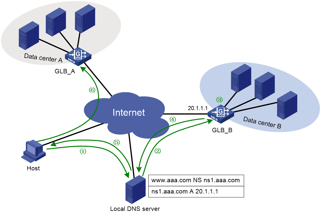
Table 1 Workflow description
|
Description |
Source IP address |
Destination IP address |
|
1. The host sends a request to the local DNS server. |
Host IP |
Local DNS server IP |
|
2. The local DNS server sends a request to the GLB device. |
Local DNS server IP |
DNS listener IP |
|
3. The GLB device uses a scheduling algorithm to select the optimal virtual server pool among all global virtual server pools. Then, it uses a scheduling algorithm to select the optimal virtual server from the optimal virtual server pool. |
N/A |
N/A |
|
4. The GLB device sends the IP address of the optimal virtual server in a DNS response to the local DNS server. |
DNS listener IP |
Local DNS server IP |
|
5. The local DNS server sends the IP address of the optimal virtual server to the host. |
Local DNS server IP |
Host IP |
|
6. The host initiates a connection request to the virtual server. |
Host IP |
VSIP |
For distributed deployment, the host sends a connection request to the SLB device instead of the GLB device.
|
|
You must contact the ISP to configure a delegating domain on the local DNS server to specify the GLB device as the authoritative DNS server. |
Relationship between configuration items
When the GLB device receives a DNS request with the destination address as the IP address of the global DNS listener, it performs the following operations:
1. Selects a global DNS mapping according to the domain name in the DNS request.
2. Selects a global virtual sever pool according to the predictors configured for the selected global DNS mapping.
3. Selects the optimal virtual sever according to the predictors configured for the selected global virtual sever pool.
4. Sends the IP address of the optimal virtual sever to the user in a DNS response.
The user uses the IP address of the optimal virtual sever as the destination IP address to access the intranet server.
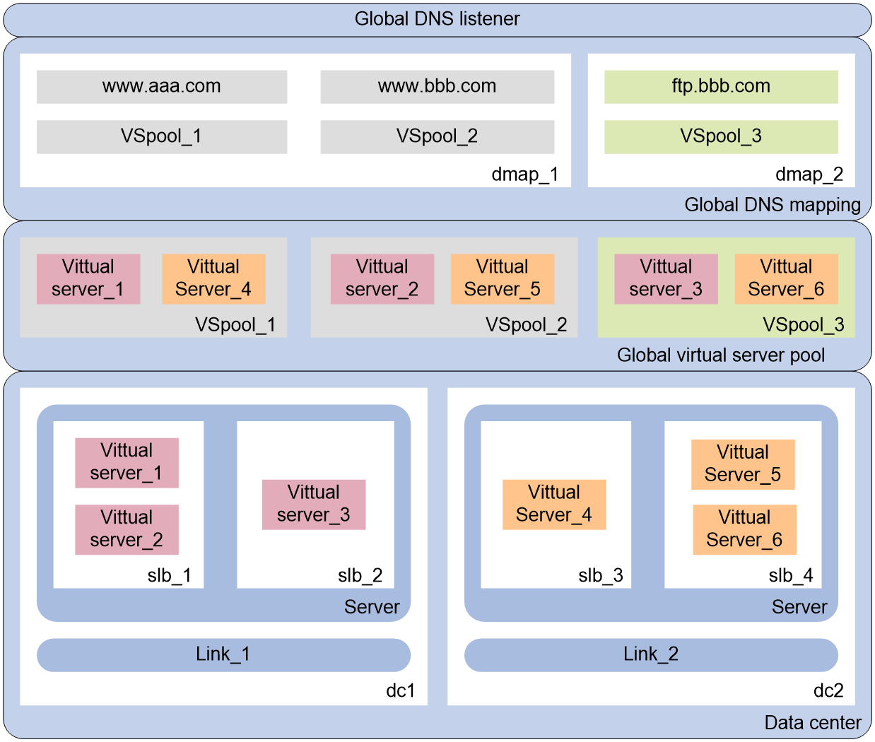
Figure 2 shows the relationship between the following configuration items:
· Global DNS listener—Listens DNS requests on the LB device. If the destination address of a DNS request matches the address being listened, GLB is performed.
· Global DNS mapping—Maps a global virtual server pool to a domain name. The GLB device can obtain the global virtual server pool associated with the domain according to the global DNS mapping. Multiple global virtual server pools can be configured in a global DNS mapping. The optimal global virtual server pool is selected according to the scheduling algorithm.
· Global virtual server pool—The virtual servers in the global virtual server pool are associated with links. The availability of the links and virtual servers determines whether the virtual servers can participate in scheduling.
· Data center—A collection of outbound links and SLB devices in a data center.
· Link—An outbound link of a data center. The bandwidth usage of the link determines whether the link is busy, and it also serves as the basis for the bandwidth algorithm.
· Topology—Associates the region where the local DNS server resides with the IP address of a virtual server to distribute DNS requests to the virtual server.
· Server—SLB device. The GLB device obtains the configuration and statistics of virtual servers from an SLB device by establishing a connection with the SLB device.
· Virtual server—A virtual server is used by the LB device to provide services to users.
Figure 2 Relationship between configuration items
Restrictions and guidelines
GLB supports only IPv4 and does not support VPN or IPv6.
The name of the virtual server configured on a GLB device or SLB device must be unique.
The name of the link configured on a GLB device must be unique.
Execute the configuration synchronization command if either of the following situations occurs:
· The connection between GLB devices has problems.
· Configuration conflicts exist after the connection between GLB devices is established.
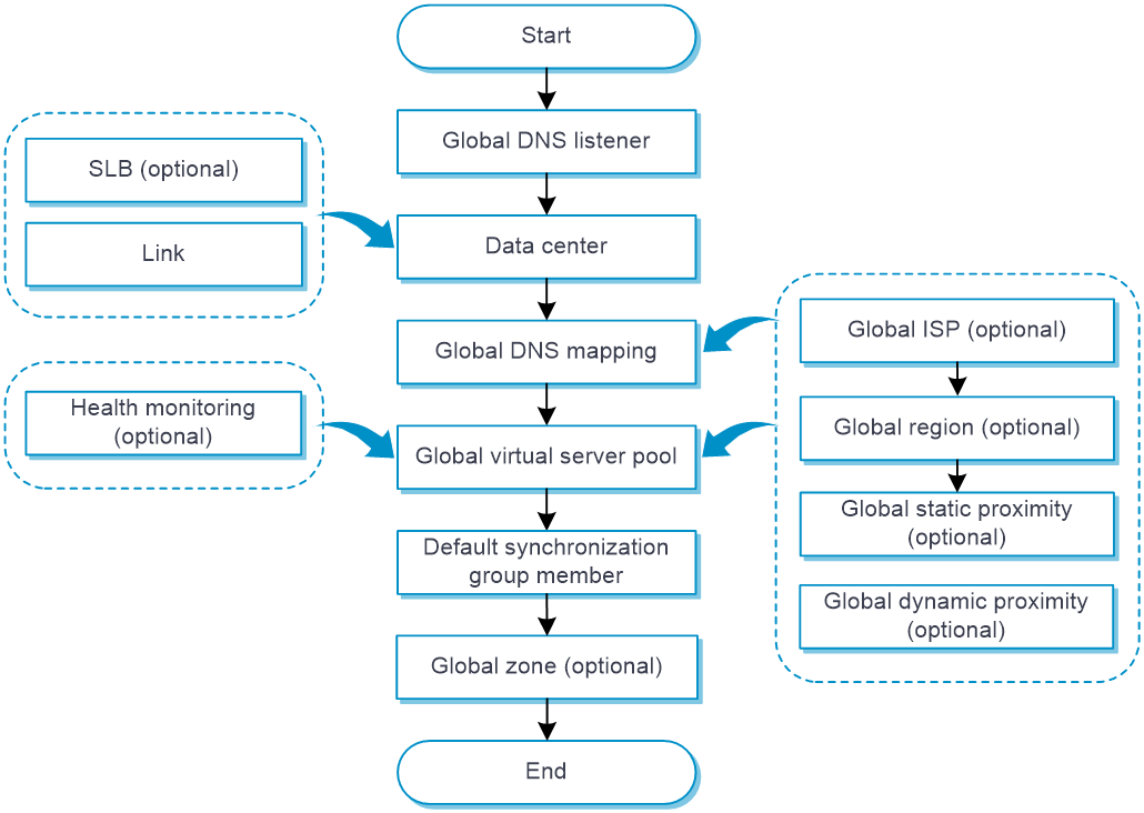
Configure global load balancing
Figure 3 shows the global load balancing configuration procedure.
Figure 3 Global load balancing configuration procedure
Configure a link
Link availability is one factor for determining whether a virtual server or virtual IP address can participate in scheduling. You can affect link availability by configuring health monitoring, the maximum bandwidth, and bandwidth ratio. For detailed steps required to configure links, see the online help for load balancing common configuration.
Configure a virtual server
For distributed deployment, GLB learns the virtual server from the SLB device. Make sure the virtual server configured on the SLB device is available.
For centralized deployment, SLB settings must be configured on the GLB device. GLB uses the locally configured virtual server. For detailed steps required to configure virtual servers, see the online help for application load balancing.
Do not configure the IP address of the virtual server as that of the global DNS listener.
The IPv4 address of a virtual server must be a non-all-zero unicast address with a 32-bit mask.
Virtual server settings can be synchronized among GLB devices through the default synchronization group.
Configure health monitoring
The GLB device uses a probe template to detect the health of the global virtual server pool, virtual IP address, and virtual servers.
For detailed steps required to configure health monitoring, see the online help for health monitoring.
Configure a global DNS listener
A global DNS listener listens DNS requests on the LB device. If the destination address of a DNS request matches the address being listened, global load balancing is performed.
Global DNS listener settings are configured on each GLB device locally, and are not synchronized among data centers.
Procedure
1. Select Policies > Load Balancing > Global Load Balancing > Global DNS Listener.
2. Click Create on the Global DNS Listener page.
3. Create a global DNS listener.
Table 2 Global DNS listener configuration items
|
Item |
Description |
|
DNS listener name |
Enter a name for the global DNS listener, case insensitive. |
|
DNS listener IP address |
Specify an IPv4 address for the DNS listener. The IPv4 address cannot be a loopback address, multicast address, broadcast address, or an address in the format of 0.X.X.X. |
|
Listening port number |
Specify a port number for the DNS listener. |
|
DNS listening |
Enable or disable DNS listening. |
|
Action upon DNS mapping search failure |
Specify the action to take upon DNS mapping search failure. · Do not respond · Send a DNS reject |
4. Click OK. The new global DNS listener appears on the Global DNS Listener page.
Configure a data center
Perform this task to define a data center and configure the mappings between the SLB device and links.
Data center settings can be synchronized among GLB devices through the default synchronization group.
Procedure
1. Select Policies > Load Balancing > Global Load Balancing > Data Center.
2. Click Create on the Data Center page.
3. Create a data center.
Table 3 Data center configuration items
|
Item |
Description |
|
Data center name |
Enter a name for the data center, case insensitive. |
|
Server LB device |
Configure an SLB device. 1. Click Add to add an SLB device. ¡ Server LB device name—Enter a name, case insensitive. By default, when a data center is created, the system automatically creates a local SLB device named localhost. ¡ Virtual server—Specify the virtual server to be referenced by the local SLB device localhost. This parameter is available only for the local SLB device localhost. The virtual servers of non-local SLB devices are automatically learned. ¡ Communication address—Specify the IPv4 address used to establish the connection between the GLB device and SLB device. ¡ Communication interval—Specify the interval at which the GLB device obtains the configuration and statistics of the virtual server from the SLB device. ¡ Username—Specify the username used to establish a connection between the GLB device and SLB device. ¡ Password—Specify the password used to establish a connection between the GLB device and SLB device. The connection can be established only if the username and password are the same as the username and password configured on the SLB device. ¡ Service capability—Enable or disable the SLB device. If the SLB device is disabled, all virtual servers of the SLB device are unavailable. 2. Click OK. The new SLB device appears on the SLB device list. |
|
Outbound link |
Select an existing link or create a link as the outbound link for the data center. A created link can be viewed from Policies > Load Balancing > Common Configuration > Links. |
|
Data center feature |
Enable or disable the data center. If the data center is disabled, all SLB devices, links, and virtual servers of the data center are unavailable. |
|
Description |
Enter a description for the data center. |
4. Click OK. The new data center appears on the Data Center page.
Configure a global DNS mapping
A DNS mapping associates a domain name with a global virtual IP pool. The LB device can obtain the virtual IP pool associated with the domain name in a DNS request.
Global DNS mapping settings can be synchronized among GLB devices through the default synchronization group.
Procedure
1. Select Policies > Load Balancing > Global Load Balancing > Global DNS Map.
2. Click Create on the Global DNS Map page.
3. Create a global DNS mapping.
Table 4 Global DNS mapping configuration items
|
Item |
Description |
|
Global DNS mapping name |
Enter a name for the global DNS mapping, case insensitive. |
|
Preferred predictor |
Select the preferred predictor for the global DNS mapping. The preferred predictor has the highest priority. If no global virtual server pool is selected by using the preferred predictor, the alternative predictor is used. If no global virtual server pool is selected by using the alternative predictor, the backup predictor is used. You can specify one of the following predictors as the preferred predictor: · Round robin—Assigns DNS requests to global virtual server pools based on the weights of global virtual server pools. A higher weight indicates more DNS requests will be assigned. · Random—Randomly assigns DNS requests to global virtual server pools. · Static proximity algorithm—Assigns DNS requests to global virtual server pools based on static proximity entries. · Dynamic proximity algorithm—Assigns DNS requests to global virtual servers based on dynamic proximity entries. By default, the round robin algorithm is used. |
|
Alternative predictor |
Specify the alternative predictor for the global DNS mapping. The supported predictors are the same as those supported for the preferred predictor. |
|
Backup predictor |
Specify the backup predictor for the global DNS mapping. The supported predictors are the same as those supported for the preferred predictor. |
|
Global virtual server pool |
Add a global virtual server pool. 1. Click Add to add a global virtual server pool. ¡ Global virtual server pool—Select an existing global virtual server pool or create a global virtual server pool. A created global virtual server pool can be viewed from Policies > Load Balancing > Global Load Balancing > Global Virtual Server Pool. ¡ Weight—Specify the weight of the global virtual server pool. A higher weight indicates more DNS requests will be assigned. 2. Click OK. The new global virtual server pool appears on the global virtual server pool list. |
|
Domain name list |
Add a domain name. 1. Enter a domain name, a case-insensitive string. Each dot-separated label in the domain name can contain a maximum of 63 characters. The domain name can contain letters, digits, hyphens (-), underscores (_), dots (.), and wildcards (asterisks and question marks). Dots cannot be used as the start and end characters. When you use wildcards (asterisks and question marks) in a domain name, follow these guidelines: ¡ The wildcards can substitute any characters except for dots (.). ¡ An asterisk (*) can substitute a character string. ¡ A question mark (?) can substitute a single character. 2. Click Add. The added domain name appears in the domain name list. |
|
TTL |
Specify the TTL in seconds. The TTL is the amount of time that DNS records are cached for DNS responses. For the DNS client to get the updated DNS record when the virtual IP address configuration changes, set a smaller TTL value. For stable, fast domain name resolution when the network is stable, set a larger TTL value. |
|
Global DNS mapping |
Enable or disable global DNS mapping. |
4. Click OK. The new global DNS mapping appears on the Global DNS Map page.
Configure a global virtual IP pool
Perform this task to facilitate management of virtual IP addresses or virtual servers with similar functions. A global virtual IP pool is used by a DNS mapping.
Global virtual IP pool settings can be synchronized among GLB devices through the default synchronization group.
Procedure
1. Select Policies > Load Balancing > Global Load Balancing > Global Virtual Pool.
2. Click Create on the Global Virtual IP Pool page.
3. Create a global virtual IP pool.
Table 5 Global virtual IP pool configuration items
|
Item |
Description |
|
Global virtual IP pool name |
Enter a name for the global virtual IP pool, case insensitive. |
|
Preferred predictor |
Specify the preferred predictor for the global virtual IP pool. The preferred predictor has the highest priority. If no virtual IP address/virtual server is selected by using the preferred predictor, the alternative predictor is used. If no virtual IP address/virtual server is selected by using the alternative predictor, the backup predictor is used. You can specify one of the following predictors as the preferred predictor: · Weight round robin—Assigns DNS requests to virtual IP addresses/virtual servers based on the weights of virtual IP addresses/virtual servers. A higher weight indicates more DNS requests will be assigned. · Random—Randomly assigns DNS requests to virtual IP addresses/virtual servers. · Static proximity—Assigns DNS requests to virtual IP addresses/virtual servers based on static proximity entries. · Dynamic proximity—Assigns DNS requests to virtual IP addresses/virtual servers based on dynamic proximity entries. · First available—Assigns all subsequent DNS requests to the virtual IP address/virtual server to which the first DNS request is assigned. For the first DNS request, the virtual IP address/virtual server with the greatest weight value is assigned. If multiple virtual IP address/virtual servers with the same greatest weight value exist, a virtual IP address/virtual server is randomly selected among them. By default, the weighted round robin algorithm is used. |
|
Alternative predictor |
Specify the alternative predictor for the global virtual IP pool. The supported predictors are the same as those supported for the preferred predictor. |
|
Backup predictor |
Specify the backup predictor for the global virtual IP pool. The supported predictors are the same as those supported for the preferred predictor. |
|
Virtual IP/Virtual server list |
1. Click Create to add a virtual IP address or virtual server. ¡ Virtual server—Virtual server learned. For centralized deployment, it is configured on the local SLB device named localhost. ¡ SLB device—Specify the SLB device to which the virtual IP address belongs. It is can only be the local SLB device named localhost. ¡ Link—Specify the link to be associated with the virtual IP address/virtual server. You can select an existing link or create a link. A created link can be viewed from Policies > Load Balancing > Common Configuration > Links. If no link is specified or the specified link is deleted, the system automatically selects the link closest to the network segment to associate with the virtual IP address/virtual server. A manually specified link overwrites an automatically selected link. ¡ Weight—Specify the weight for the virtual IP address/virtual server. For the weighted round robin algorithm, a greater value means a higher priority to be used. ¡ Probe method—Specify a probe template for the virtual IP address/virtual server. You can select an existing probe template or create a probe template. A created probe template can be viewed from Objects > Health Monitoring. ¡ Success criteria—Specify the health monitoring success criteria for the virtual IP address/virtual server. All probes succeed—Health monitoring succeeds only when all the specified health monitoring methods succeed. At least n probes succeed—Health monitoring succeeds when a minimum of the specified number of health monitoring methods succeed. When the specified number of health monitoring methods is greater than the number of health monitoring methods on the device, health monitoring succeeds if all health monitoring methods succeed. 2. Click OK. The new virtual IP address/virtual server appears in the virtual IP address/virtual server list. |
|
Probe method |
Specify a probe template for the global virtual IP pool to detect health and availability of the virtual IP address/virtual servers. You can also configure this parameter for a single virtual IP address/virtual server. The configuration for a single virtual IP address/virtual server has higher priority than that for the global virtual IP pool. You can select an existing probe template or create a probe template. A created probe template can be viewed from Objects > Health Monitoring. |
|
Success criteria |
Specify the health monitoring success criteria for the global virtual IP pool. · All probes succeed—Health monitoring succeeds only when all the specified health monitoring methods succeed. · At least n probes succeed—Health monitoring succeeds when a minimum of the specified number of health monitoring methods succeed. When the specified number of health monitoring methods is greater than the number of health monitoring methods on the device, health monitoring succeeds if all health monitoring methods succeed. |
|
Link protection |
Enable or disable link protection. This feature enables a global virtual IP pool to select a virtual IP address/virtual server based on the bandwidth ratio of the associated link. If the bandwidth ratio of a link is exceeded, the virtual IP address or virtual server is not selected. You can set the bandwidth ratio of a link from Policies > Load Balancing > Common Configuration > Links. |
4. Click OK. The new global virtual IP pool appears on the Global Virtual IP Pool page.
Configure a default synchronization group member
GLB requires synchronization of configuration and statistics among multiple GLB devices for unified management.
Each GLB device is a member of a synchronization group. Data is synchronized only among members in the same synchronization group. Currently, all GLB devices are members of the default synchronization group.
Procedure
1. Select Policies > Load Balancing > Global Load Balancing > Default Syncgroup Member.
2. Click Create on the Default Syncgroup Member page.
3. Create a default synchronization group member.
Table 6 Default synchronization group member configuration items
|
Item |
Description |
|
Default synchronization group member name |
Enter a name for the default synchronization group member, case insensitive. |
|
Member type |
Specify the member type: Local or Remote. |
|
Member communication capability |
Enable or disable member communication capability. A local synchronization group member can establish a TCP connection with a remote synchronization group member only if member communication capability is enabled. |
|
Communication address |
Specify the IPv4 address used to establish a TCP connection with the remote synchronization group member. |
|
Communication port |
Specify the port number used to establish a TCP connection with the remote synchronization group member. |
|
Authentication key |
Enter an authentication key used for establishing a TCP connection between the local and remote synchronization group members. A TCP connection can be established only if the authentication keys are the same on the local and remote synchronization group members. This parameter can be configured only on the local synchronization group member. |
|
Probe interval |
Specify the interval at which the local synchronization group member sends keepalive packets to the remote synchronization group member after establishing a connection with it. This parameter can be configured only on the local synchronization group member. |
|
Probe retry times |
Specify the number of keepalive retries for the local synchronization group member. This parameter can be configured only on the local synchronization group member. |
4. Click OK. The new default synchronization group member appears on the Default Syncgroup Member page.
Configure global ISP information
Use the IP addresses assigned by ICANN to configure IP addresses for an ISP.
You can configure ISP information manually, by importing an ISP file, or use both methods.
The system keeps the imported information intact when detecting the following problems on the imported file:
· The file does not exist.
· The file name is invalid.
· File decryption fails.
If the system quits the import operation because of IP address parsing failure, the system performs the following operations:
· Clears the most recently imported information.
· Saves the information imported this time.
You cannot delete the imported ISP or its IPv4 or IPv6 address. If the manually configured and imported ISP information overlaps, you can delete the manually configured ISP information.
If you import multiple ISP files, the newly imported file overwrites the previously imported one.
Procedure
1. Select Policies > Load Balancing > Global Load Balancing > Global ISP.
2. Import an ISP file on the Global ISP page.
a. Click Select, and select the file to be imported.
b. Click Import. The imported file appears in the ISP list.
3. Manually configure global ISP information.
a. Click Create.
Table 7 Manual global ISP configuration items
|
Item |
Description |
|
Global ISP name |
Enter a name for the global ISP, case insensitive. |
|
ISP address list |
1. Click Create to configure an ISP address. ¡ IPv4 address—Enter an IPv4 address. ¡ Mask length—Specify the mask length for the IPv4 address. 2. Click OK. The ISP address appears in the ISP address list. ¡ Origin—The way an ISP address is obtained. Options are Manually configured and Imported from file. |
b. Click OK. The new global ISP appears in the global ISP list.
Configure a global region
A global region contains network segments corresponding to different global ISPs.
Procedure
1. Select Policies > Load Balancing > Global Load Balancing > Global Region.
2. Click Create on the Global Region page.
3. Create a global region.
Table 8 Global region configuration items
|
Item |
Description |
|
Global region name |
Enter a name for the global region, case insensitive. |
|
Global ISP |
Add a global ISP by selecting an existing global ISP or creating a global ISP. A created global ISP can be viewed from Policies > Load Balancing > Global Load Balancing > Global ISP. |
4. Click OK. The new global region appears on the Global Region page.
Configure global static proximity
A global static proximity policy associates a global region with a virtual IP address range and a global virtual IP pool. When the static proximity algorithm is specified for a global DNS mapping or global virtual IP pool, you must configure a global static proximity policy. When a DNS request matches multiple global static proximity policies, the static proximity policy with the highest weight is used.
Procedure
1. Select Policies > Load Balancing > Global Load Balancing > Global Topology.
2. Click Create on the Global Topology page.
3. Create a global static proximity policy.
Table 9 Global static proximity policy configuration items
|
Item |
Description |
|
Global region name |
Select an existing global region or create a global region. A created global region can be viewed from Policies > Load Balancing > Global Load Balancing > Global Region. |
|
IPv4 subnet |
Specify the IPv4 address range in the form of IPv4 address/mask length. The mask length is in the range of 0 to 32. If the mask length is 32, the most significant eight bits must be smaller than 224 and cannot be 0 or 127. |
|
Global virtual IP pool |
Select an existing global virtual IP pool or create a global virtual IP pool. A created global virtual IP pool can be viewed from Policies > Load Balancing > Global Load Balancing > Global Virtual Pool. |
|
Priority |
Specify a priority value. When a DNS request matches multiple static proximity policies, the static proximity policy with the greatest priority value is selected. |
4. Click OK. The new global static proximity policy appears on the Global Topology page.
Configure global dynamic proximity
The global dynamic proximity feature performs link detection to select the optimal link to a destination.
This task is required when the dynamic proximity algorithm is specified for a global DNS mapping or global virtual IP pool. To use the global dynamic proximity feature, configure the proximity parameters and then enable the proximity feature to generate global proximity entries.
Procedure
1. Select Policies > Load Balancing > Global Load Balancing > Global Proximity > Global Proximity Parameter.
2. Click Create on the Global Proximity Parameter page.
3. Create a global proximity parameter.
Table 10 Global proximity parameter configuration items
|
Item |
Description |
|
Default probe method |
Specify the default global probe template. You can select an existing global probe template or create a global probe template. A created probe template can be viewed from Objects > Health Monitoring. |
|
IPv4 mask length |
Specify the mask length for IPv4 global proximity entries. The value 0 indicates the natural mask. |
|
Aging time |
Set the timeout timer for global proximity entries. |
|
TTL weight |
Set the TTL weight for global proximity calculation. A larger value indicates a higher weight. |
|
RTT weight |
Set the network delay weight for global proximity calculation. A larger value indicates a higher weight. |
|
Cost weight |
Set the cost weight for global proximity calculation. A larger value indicates a higher cost weight. |
|
Bandwidth weight |
Set the bandwidth weights for global proximity calculation. · Inbound—Set the inbound link bandwidth weight for global proximity calculation. A larger value indicates a higher bandwidth weight. · Outbound—Set the outbound link bandwidth weight for global proximity calculation. A larger value indicates a higher bandwidth weight. |
|
Max entries |
Set the maximum number of global proximity entries. The value 0 means not limited. |
4. Click OK. The new global proximity parameter appears on the Global Proximity Parameter page.
Configure a global forward DNS zone
During DNS resolution, an LB device looks up the resource records configured in a global forward DNS zone for the host name corresponding to the target domain name. The following types of DNS resource records are available for an LB device to resolve DNS requests:
· Canonical name (CNAME)—Maps multiple aliases to one host name (server). For example, an enterprise intranet has a server with host name host.aaa.com. The server provides both Web service and mail service. You can configure two aliases (www.aaa.com and mail.aaa.com) in a CNAME resource record for this server. When a user requests Web service, the user accesses www.aaa.com. When a user requests mail service, the user accesses mail.aaa.com. Actually, the user accesses host.aaa.com in both cases.
· Mail exchanger (MX)—Specifies the mail server for a global forward DNS zone.
· Name server (NS)—Specifies the authoritative DNS server for a global forward DNS zone.
· Start of authority (SOA)—Specifies authoritative information about a global forward DNS zone, including the primary DNS server and administrator mailbox.
After receiving a DNS request, an LB device searches the resource records in the configured global forward DNS zone for the host name corresponding to the target domain name. Then, the LB device looks up the DNS mappings for the global virtual IP pool associated with the host name.
Procedure
1. Select Policies > Load Balancing > Global Load Balancing > Global Zone > Global Forward DNS Zone.
2. Click Create on the Global Forward DNS Zone page.
3. Create a global forward DNS zone.
Table 11 Global forward DNS zone configuration items
|
Item |
Description |
|
Zone name |
Specifies a domain name for the global forward DNS zone, a case-insensitive, dot-separated string of 1 to 253 characters. Each dot-separated part in the domain name can contain a maximum of 63 characters. The domain name can contain letters, digits, hyphens (-), underscores (_), and dots (.). |
|
TTL |
Specify the TTL for all resource records in the global forward DNS zone. |
|
Resource record list |
1. Click Create to add a resource record. ¡ Type—Select a resource type: MX, NS, or CNAME. ¡ Subname—Specify a subname for the global forward DNS zone, a case-insensitive, dot-separated string of 1 to 254 characters. The string can contain letters, digits, hyphens (-), underscores (_), and dots (.). Each dot-separated part can have a maximum of 63 characters. This parameter appears only if you have selected MX or NS from the Type list. ¡ Mail server host name—Specify the host name of the mail server, a case-insensitive, dot-separated string that contains a maximum of 254 characters. The string can contain letters, digits, hyphens (-), underscores (_), and dots (.). Each dot-separated part can have a maximum of 63 characters. This parameter appears only if you have selected MX from the Type list. ¡ Priority—Specify the preference for the resource record. The smaller the value, the higher the priority. This parameter appears only if you have selected MX from the Type list. ¡ Authoritative name server host name—Specify the host name of the authoritative DNS server, a case-insensitive, dot-separated string that contains a maximum of 254 characters. The string can contain letters, digits, hyphens (-), underscores (_), and dots (.). Each dot-separated part can have a maximum of 63 characters. This parameter appears only if you have selected NS from the Type list. ¡ Alias—Specify an alias for a host name, a case-insensitive, dot-separated string that contains a maximum of 254 characters. The string can contain letters, digits, hyphens (-), underscores (_), and dots (.). Each dot-separated part can have a maximum of 63 characters. This parameter appears only if you have selected CNAME from the Type list. ¡ Canonical name—Specify the host name, a case-insensitive, dot-separated string that contains a maximum of 254 characters. The string can contain letters, digits, hyphens (-), underscores (_), and dots (.). Each dot-separated part can have a maximum of 63 characters. This parameter appears only if you have selected CNAME from the Type list. 2. Click OK. The new resource record appears in the resource record list. |
|
SOA configuration-Primary name server host name |
Specify the host name for the primary DNS server. The host name of the primary DNS server can be a relative domain name (does not end with a dot) or an absolute domain name (ends with a dot). For an absolute domain name, the host name is not automatically expanded and cannot exceed 254 characters. For a relative domain name, the current domain name is automatically appended to the host name. The host name plus the appended domain name cannot exceed 254 characters. |
|
SOA configuration-Administrator email address |
Specify the email address of the administrator. The email address of the administrator can be a relative domain name (does not end with a dot) or an absolute domain name (ends with a dot). For an absolute domain name, the email address is not automatically expanded and cannot exceed 254 characters. For a relative domain name, the current domain name is automatically appended to the email address. The email address plus the appended domain name cannot exceed 254 characters. |
|
SOA configuration-Serial number |
Configure the serial number for the global forward DNS zone. The greater the serial number, the newer the global forward DNS zone is configured. The secondary DNS server periodically queries the serial numbers of global forward DNS zones on the primary DNS server and compares them with local serial numbers. |
|
SOA configuration-Refresh interval |
Specify the refresh interval. The secondary DNS server obtains SOA resource records from the primary DNS server at the refresh interval. After obtaining SOA resource records, the secondary DNS server compares them with the local SOA resource records. |
|
SOA configuration-Retry interval |
Specify the retry interval, which is the amount of time that the secondary DNS server waits after it fails to copy a global forward DNS zone. |
|
SOA configuration-Expiration time |
Specify the expiration time, which is the amount of time that the secondary DNS server can work after it loses contact with the primary DNS server. |
|
SOA configuration-Minimum TTL |
Specify the minimum TTL, which is the amount of time that resource records on the primary DNS server are cached on the secondary DNS server. |
4. Click OK. The global forward DNS zone appears on the Global Forward DNS Zone page.
Configure a global reverse DNS zone
The LB device performs reverse DNS resolution according to the global reverse DNS zone configuration. Reverse DNS resolution searches for a domain name according to an IP address. The pointer record (PTR) resource records configured in global reverse DNS zone record mappings between domain names and IP addresses.
Reverse DNS resolution is used to address spam attacks by verifying the validity of the email sender. When a mail server receives an email from an external user, it sends a reverse DNS resolution request to the LB device. The LB device resolves the source IP address of the sender into a domain name according to PTR resource records, and sends the domain name to the mail server. The mail server compares the received domain name with the actual domain name of the sender. If the two domain names match, the mail server accepts the email. If not, the mail server considers the email as a spam email and discards it.
Procedure
1. Select Policies > Load Balancing > Global Load Balancing > Global Zone > Global Reverse DNS Zone.
2. Click Create on the Global Reverse DNS Zone page.
3. Create a global reverse DNS zone.
Table 12 Global reverse DNS zone configuration items
|
Item |
Description |
|
IPv4 address |
Specify an IPv4 address for the global reverse DNS zone. |
|
Mask |
Specify the mask length for the global reverse DNS zone. |
|
TTL |
Specify the TTL for PTR resource records. |
|
PTR resource record list |
1. Click Create to add a PTR resource record. ¡ IPv4 address—Specify an IPv4 address. The IPv4 address specified in a PTR resource record must be within the IPv4 address range of the global reverse DNS zone. ¡ Domain name—Specify a domain name, a case-insensitive, dot-separated string that contains a maximum of 253 characters. The string can contain letters, digits, hyphens (-), underscores (_), and dots (.). Each dot-separated part can have a maximum of 63 characters. 2. Click OK. The new PTR resource record appears in the PTR resource record list. |
4. Click OK. The global reverse DNS zone appears on the Global Reverse DNS Zone page.
Configure data synchronization
Perform this task to synchronize data among default synchronization group members. The following settings and their running information can be synchronized:
· Data center.
· SLB device.
· Global DNS mapping.
· Global virtual IP pool.
· Virtual server.
· Link.
· Global forward DNS zone.
· Global reverse DNS zone.
· Global ISP (excluding imported ISP files).
· Global region.
· Global static proximity.
· Global dynamic proximity (excluding probe methods).
The device supports two synchronization methods: Synchronize local data and Synchronize to all. For the master device, the two synchronization methods have the same effect, that is, synchronizing the master's data to all standby devices in the default synchronization group. For a standby device, Synchronize local data synchronizes its data to the master device, and Synchronize to all notifies the master to synchronize data on the master to all standby devices.
For the configuration to take effect, perform this task after the master device has been elected.