- Table of Contents
- Related Documents
-
| Title | Size | Download |
|---|---|---|
| 05-SRv6-TE policy configuration | 240.65 KB |
Contents
SRv6-TE policy traffic steering
SRv6-TE policy forwarding procedure
MPLS L3VPN/EVPN L3VPN over SRv6-TE policy
SRv6-TE policy tasks at a glance
Configuring SRv6-TE policy attributes
Configuring BGP to advertise SRv6-TE policy routes
Restrictions and guidelines for SRv6-TE policy routes advertisement
Enabling BGP to advertise SRv6-TE policy routes
Configuring BGP to redistribute SRv6-TE policy routes
Enabling advertising SRv6-TE policy routes to EBGP peers
Configuring BGP to control SRv6-TE policy route selection and advertisement
Configuring SRv6-TE policy traffic steering
Configuring traffic forwarding statistics for SRv6-TE policies
Configuring MPLS L3VPN or EVPN L3VPN over SRv6-TE policy
Display and maintenance commands for SRv6-TE policies
SRv6-TE policy configuration examples
Example: Configuring SRv6-TE policy-based forwarding
Configuring SRv6-TE policies
About SRv6-TE policies
IPv6 Segment Routing Traffic Engineering (SRv6-TE) policies apply to scenarios where multiple paths exist between a source node and a destination node on an SRv6 network. The device can use an SRv6-TE policy to flexibly steer traffic to a proper forwarding path.
SRv6-TE policy identification
An SRv6-TE policy is identified by the following items:
· BSID—SID of the ingress node.
· Color—Color attribute for the forwarding path. You can use the color attribute to distinguish an SRv6-TE policy from other SRv6-TE policies that are configured for the same source and destination nodes.
· End point—IPv6 address of the destination node.
SRv6-TE policy contents
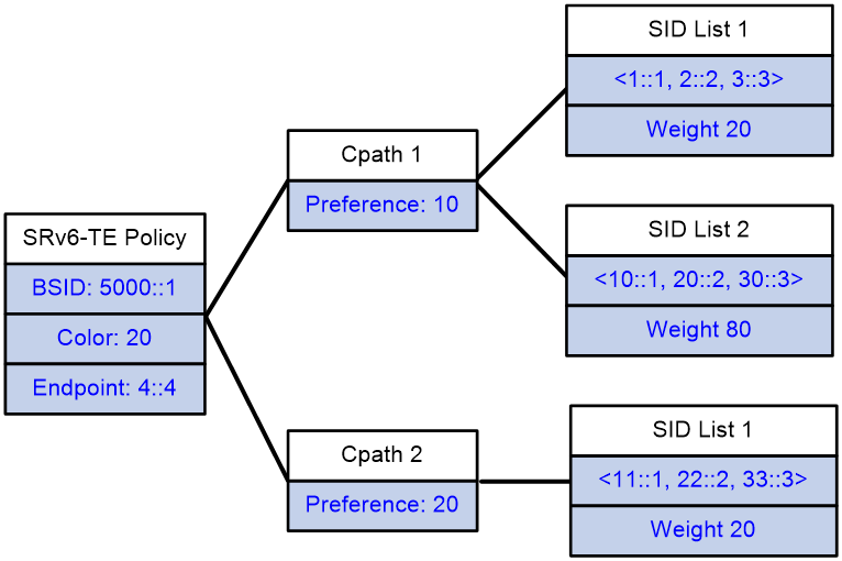
As show in Figure 1, an SRv6-TE policy consists of candidate paths with different preferences. Each candidate path can have one or multiple subpaths identified by segment lists (also called SID lists).
· Candidate path
An SRv6-TE policy can have multiple candidate paths. Candidate paths are uniquely identified by their preference values. An SRv6-TE policy chooses a candidate path from all its candidate paths based on the preference values to forward traffic.
Two SRv6-TE policies cannot share the same candidate path.
· SID list
A SID list is a list of SIDs that indicates a packet forwarding path. Each SID is the IPv6 address of a node on the forwarding path.
A candidate path can have a single SID list or multiple SID lists that use different weight values. After an SRv6-TE policy chooses a candidate path with multiple SID lists, the traffic will be load shared among the SID lists based on weight values.
Figure 1 SRv6-TE policy contents
SRv6-TE policy creation
An SRv6-TE policy can be created in the following modes:
· Manual configuration from CLI
In this method, you need to manually configure the candidate settings for the SRv6-TE policy, such as candidate path preferences, SID lists and weights.
· Learning from an SRv6-TE policy route
To support SRv6-TE policy, MP-BGP defines the BGP IPv6 SR address family and the SRv6-TE policy Network Layer Reachability Information (NLRI). The SRv6-TE policy NLRI is called the SRv6-TE policy route (or BGP IPv6 SR policy). An SRv6-TE policy route contains SRv6-TE policy settings, including the BSID, color, endpoint, candidate preferences, SID lists, and SID list weights.
The device can advertise its local SRv6-TE policy settings to its BGP IPv6 SR policy peer through an SRv6-TE policy route. The peer device can create an SRv6-TE policy according to the received SRv6-TE policy settings.
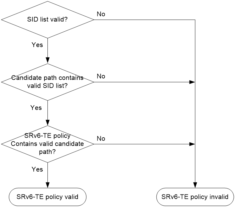
SRv6-TE policy validity
An SRv6-TE policy must be valid in order to ensure successful traffic forwarding.
The following describes the rules for identifying the validity of an SRv6-TE policy:
1. An SRv6-TE policy is valid only if it has valid candidate paths.
2. A candidate path is valid only if it has a valid SID list.
3. A SID list is valid if none of the following situations exists:
¡ The SID list is empty.
¡ The weight of the SID list is 0.
¡ An SR node and the first IPv6 address in the SID list cannot reach each other.
Figure 2 SRv6-TE policy validity determination
SRv6-TE policy traffic steering
The following modes are available to steer traffic to an SRv6-TE policy:
· BSID—If the destination IPv6 address of a received packet is the BSID of an SRv6-TE policy, the device uses the SRv6-TE policy to forward the packet.
· Color—The device searches for an SRv6-TE policy whose color and endpoint address match the color and nexthop address of a BGP route. If a matching SRv6-TE policy exists, the device recurse the BGP route to that SRv6-TE policy. Then, when the device receives packets that match the BGP route, it forwards the packets through the SRv6-TE policy.
· Tunnel policy—-On the ingress PE of an MPLS L3VPN or EVPN L3VPN network, create an SRv6-TE policy with endpoint address as an End.DT4 SID, End.DT6 SID, or End.DT46 SID. Configure a preferred tunnel or load sharing tunnel policy that uses the SRv6-TE policy. In this way, the SRv6-TE policy will be used as the public tunnel to carry the packets of a VPN instance. For more information about the tunnel policy configuration, see MPLS Configuration Guide.
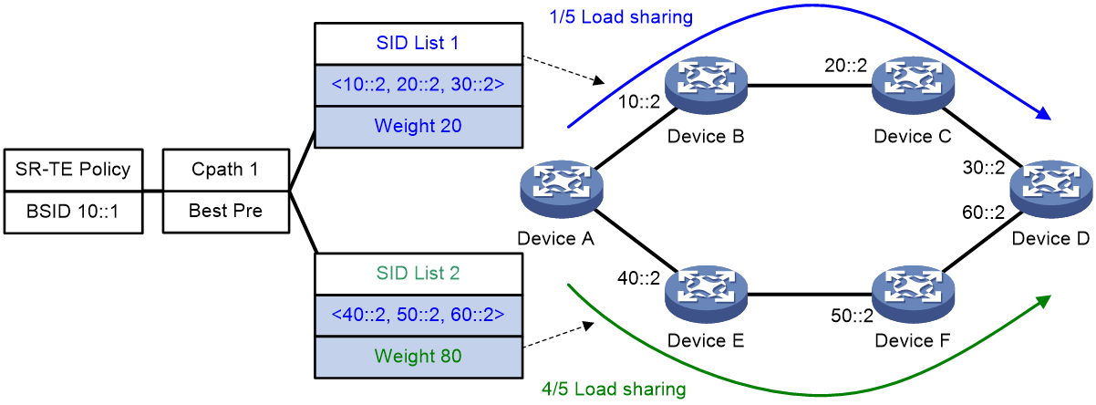
SRv6-TE policy path selection
After traffic is steered in to an SRv6-TE policy, the SRv6-TE policy selects a forwarding path for the traffic as follows:
1. Selects the valid candidate path that has the highest preference.
2. Performs Weighted ECMP (WECMP) load sharing among the SID lists of the selected candidate path. The load of SID list x is equal to Weight x/(Weight 1 + Weight 2 + … + Weight n).
For example, as shown in Figure 3, Device A first selects a valid SRv6-TE policy by BSID. Then, the device selects a candidate path by preference. The candidate path has two valid SID lists: SID list 1 and SID list 2. The weight value of SID list 1 is 20 and the weight value of SID list 2 is 80. One fifth of the traffic will be forwarded through the subpath identified by SID list 1. Four fifth of the traffic will be forwarded through the subpath identified by SID list 2.
Figure 3 SRv6-TE policy path selection
SRv6-TE policy forwarding procedure
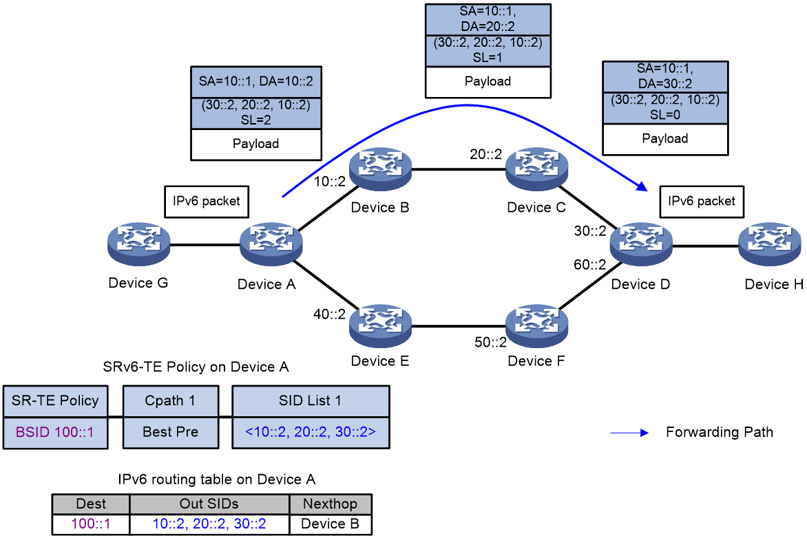
As shown in Figure 4, the SRv6-TE policy forwarding procedure is as follows (BSID-based traffic steering as an example):
1. After Device A receives a packet with destination address 100::1, it searches its IPv6 routing table and determines that the address is a BSID. Then, Device A encapsulates the packet with an SRH header according to the SRv6-TE policy of the BSID. The SRH header contains SID list {10::2, 20::2, 30::2}, where 10::2 is the SID for Device B, 20::2 is the SID for Device C, and 30::2 is the SID for Device D.
2. Device A forward the packet to the next hop Device B.
3. After Device B receives the packet, it obtains the next hop Device C from the SRH, and then forwards the packet to Device C.
4. After Device C receives the packet, it obtains the next hop Device D from the SRH, and then forwards the packet to Device D.
5. After Device D receives the packet, it identifies that the SL value is 0 in the SRH. So Device D decapsulates the packet. Device D deletes the SRH header and forwards the packet according to the destination address of the packet.
Figure 4 SRv6-TE policy forwarding diagram
MPLS L3VPN/EVPN L3VPN over SRv6-TE policy
In MPLS L3VPN over SRv6 or EVPN L3VPN over SRv6 networks, PEs can steer VPN packets into an SRv6-TE policy.
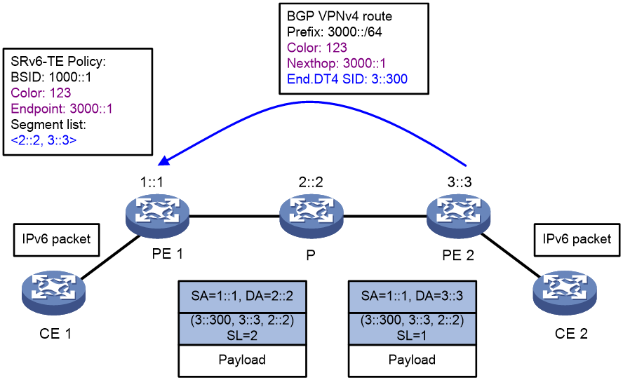
For example, in an IPv4 MPLS L3VPN over SRv6 network as shown in Figure 5, the route advertisement and packet forwarding procedures are as follows:
1. PE 2 assigns private label End.DT4 SID (3::300) to private route 3000::/64. The nexthop address and color attribute of the route is 3000::1 and 123, respectively.
2. PE 2 advertises the private label information through the BGP VPNv4 route to PE 1.
3. PE 1 steers traffic with destination 3000::/64 to a matching SRv6-TE policy.
Assume the SRv6-TE policy and color-based or tunnel policy-based traffic steering have been configured properly on PE 1.
4. After PE 1 receives a packet destined for 3000::/64, PE 1 adds the End.DT4 SID and the SID list of the SRv6-TE policy into the packet, and then forwards the packet to PE 2 over the path indicated by the SID list.
5. PE 2 matches a VPN instance for the packet by the End.DT4 SID and decapsulates the packet, and forwards the packet by looking up the routing table of the VPN instance.
Figure 5 MPLS L3VPN/EVPN L3VPN over SRv6-TE policy routing and forwarding procedure
SRv6-TE policy tasks at a glance
To configure an SRv6-TE policy, perform the following tasks:
1. Configuring IGP-based SID advertisement
Perform this task on each SRv6 node. For more information, see "Configuring IPv6 Segment Routing."
4. Configuring SRv6-TE policy attributes
5. Configuring a candidate path
6. (Optional.) Configuring BGP to advertise SRv6-TE policy routes
a. Enabling BGP to advertise SRv6-TE policy routes
b. Configuring BGP to redistribute SRv6-TE policy routes
c. (Optional.) Enabling advertising SRv6-TE policy routes to EBGP peers
d. (Optional.) Enabling Router ID filtering
e. (Optional.) Configuring BGP to control SRv6-TE policy route selection and advertisement
f. (Optional.) Maintaining BGP sessions
7. Configuring SRv6-TE policy traffic steering
8. (Optional.) Configuring traffic forwarding statistics for SRv6-TE policies
9. (Optional.) Configuring MPLS L3VPN or EVPN L3VPN over SRv6-TE policy
Configuring a SID list
About this task
After you add nodes to a SID list, the system will sort the nodes in ascending order of node index. The node with the smallest index represents the next hop of the source node on the forwarding path.
Procedure
1. Enter system view.
system-view
2. Enable SRv6 and enter SRv6 view.
segment-routing ipv6
By default, SRv6 is disabled.
3. Create and enter the SRv6 TE view.
traffic-engineering
4. Create a SID list and enter its view.
segment-list segment-list-name
5. Add a node to the SID list.
index index-number ipv6 ipv6-address
Creating an SRv6-TE policy
1. Enter system view.
system-view
2. Enter SRv6 view.
segment-routing ipv6
3. Enter SRv6 TE view.
traffic-engineering
4. Create an SRv6-TE policy and enter its view.
policy policy-name
Configuring SRv6-TE policy attributes
About this task
An SRv6-TE policy is identified by the following items: BSID, color, and end point.
You can bind a BSID to the policy manually, or set only the color and end point attributes of the policy so the system automatically assigns a BSID to the policy. If you use both methods, the manually bound BSID takes effect.
Restrictions and guidelines
The configured BSID must be on the locator specified for SRv6-TE policies in SRv6 TE view. Otherwise, the SRv6-TE policy cannot forward packets. For more information about the locator configuration, see "Configuring IPv6 Segment Routing."
Different SRv6-TE policies cannot have the same color or endpoint IP address.
Procedure
1. Enter system view.
system-view
2. Enter SRv6 view.
segment-routing ipv6
3. Enter SRv6 TE view.
traffic-engineering
4. Specify a locator for SRv6 TE.
srv6-policy locator locator-name
By default, no locator is specified for SRv6 TE.
5. Enter SRv6-TE policy view.
policy policy-name
6. Configure a BSID for the policy.
binding-sid ipv6 ipv6-address
7. Set the color and end point attributes.
color color-value end-point ipv6 ipv6-address
By default, the color and endpoint attributes of an SRv6-TE policy are not configured.
Configuring a candidate path
1. Enter system view.
system-view
2. Enter SRv6 view.
segment-routing ipv6
3. Enter SRv6 TE view.
traffic-engineering
4. Enter SRv6-TE policy view.
policy policy-name
5. Create and enter SRv6-TE policy candidate path view.
candidate-paths
6. Set the preference for a candidate path and enter SRv6-TE policy path preference view.
preference preferenc-value
By default, no candidate path preferences are set.
Each preference represents a candidate path.
7. Specify an explicit path for the candidate path.
explicit segment-list segment-list-name [ weight weight-value ]
A candidate path can have multiple SID lists.
Configuring BGP to advertise SRv6-TE policy routes
Restrictions and guidelines for SRv6-TE policy routes advertisement
For more information about BGP commands, see Layer 3—IP Routing Commands.
Enabling BGP to advertise SRv6-TE policy routes
1. Enter system view.
system-view
2. Configure a global router ID.
router id router-id
By default, no global router ID is configured.
3. Enable a BGP instance and enter its view.
bgp as-number [ instance instance-name ]
By default, BGP is disabled and no BGP instances exist.
4. Configure a peer or peer group.
peer { group-name | ipv6-address [ prefix-length ] } as-number as-number
5. Create the BGP IPv6 SR policy address family and enter its view.
address-family ipv6 sr-policy
6. Enable BGP to exchange SRv6-TE policy routing information with the peer or peer group.
peer { group-name | ipv6-address [ prefix-length ] } enable
By default, the device cannot use BGP to exchange SRv6-TE policy routing information with a peer or peer group.
Configuring BGP to redistribute SRv6-TE policy routes
About this task
After you configure BGP to redistribute SRv6-TE policy routes, the system will redistribute the local SRv6-TE policy routes to the BGP routing table and advertise the routes to peers. Then, the peers can forward traffic based on the SRv6-TE policy.
Procedure
1. Enter system view.
system-view
2. Enter BGP instance view.
bgp as-number [ instance instance-name ]
3. Enter BGP IPv6 SR policy address family view.
address-family ipv6 sr-policy
4. Enable BGP to redistribute routes from SRv6-TE policies.
import-route sr-policy
By default, BGP does not redistribute SRv6-TE policy routes.
Enabling advertising SRv6-TE policy routes to EBGP peers
About this task
By default, SRv6-TE policy routes are advertised among IBGP peers. To advertise SRv6-TE policy routes to EBGP peers, you must perform this task to enable the advertisement capability.
Procedure
1. Enter system view.
system-view
2. Enter BGP instance view.
bgp as-number [ instance instance-name ]
3. Enter BGP IPv6 SR policy address family view.
address-family ipv6 sr-policy
4. Enable advertising SRv6-TE policy routes to EBGP peers.
advertise ebgp enable
By default, SRv6-TE policy routes are not advertised to EBGP peers.
Enabling Router ID filtering
About this task
For the device to process only part of the received SRv6-TE policy routes, you can perform this task to enable filtering the routes by Router ID.
This feature enables the device to check the Route Target attribute of a received SRv6-TE policy route. The device accepts the route only if the Route Target attribute contains the Router ID of the local device.
Restrictions and guidelines
To use Router ID filtering, make sure you add Route Target attributes to SRv6-TE policy routes properly by using routing policy or other methods. Otherwise, Router ID filtering might learn or drop SRv6-TE policy routes incorrectly.
Procedure
1. Enter system view.
system-view
2. Enter BGP instance view.
bgp as-number [ instance instance-name ]
3. Enter BGP IPv6 SR policy address family view.
address-family ipv6 sr-policy
4. Enable Router ID filtering.
router-id filter
By default, Router ID filtering is disabled.
Configuring BGP to control SRv6-TE policy route selection and advertisement
1. Enter system view.
system-view
2. Enter BGP instance view.
bgp as-number [ instance instance-name ]
3. Enter BGP IPv6 SR policy address family view.
address-family ipv6 sr-policy
4. Specify the local router as the next hop for routes sent to a peer or peer group.
peer { group-name | ipv6-address [ prefix-length ] } next-hop-local
By default, BGP sets the local router as the next hop for all routes sent to an EBGP peer or peer group. BGP does not set the local router as the next hop for routes sent to an IBGP peer or peer group.
5. Allow a local AS number to exist in the AS_PATH attribute of routes from a peer or peer group, and to set the number of times the local AS number can appear.
peer { group-name | ipv6-address [ prefix-length ] } allow-as-loop [ number ]
By default, the local AS number is not allowed to exist in the AS_PATH attribute of routes from a peer or peer group.
6. Specify a preferred value for routes received from a peer or peer group.
peer { group-name | ipv6-address [ prefix-length ] } preferred-value value
By default, the preferred value is 0 for routes received from a peer or peer group.
7. Set the maximum number of routes that can be received from a peer or peer group.
peer { group-name | ipv6-address [ prefix-length ] } route-limit prefix-number [ { alert-only | discard | reconnect reconnect-time } | percentage-value ] *
By default, the number of routes that can be received from a peer or peer group is not limited.
8. Configure the device as a route reflector and specify a peer or peer group as a client.
peer { group-name | ipv6-address [ prefix-length ] } reflect-client
By default, neither the route reflector nor the client is configured.
9. Specify an IPv6 prefix list to filter routes received from or advertised to a peer or peer group.
peer { group-name | ipv6-address [ prefix-length ] } prefix-list ipv6-prefix-list-name { export | import }
By default, no prefix list based filtering is configured.
10. Apply a routing policy to routes incoming from or outgoing to a peer or peer group.
peer { group-name | ipv6-address [ prefix-length ] } route-policy route-policy-name { export | import }
By default, no routing policy is applied to routes incoming from or outgoing to a peer or peer group.
11. Advertise the COMMUNITY attribute to a peer or peer group.
peer { group-name | ipv6-address [ prefix-length ] } advertise-community
By default, no COMMUNITY attribute is advertised to any peers or peer groups.
12. Advertise the extended community attribute to a peer or peer group.
peer { group-name | ipv6-address [ prefix-length ] } advertise-ext-community
By default, no extended community attribute is advertised to any peers or peer groups.
Maintaining BGP sessions
To maintain BGP sessions, execute the following commands in user view:
· Reset BGP sessions for the BGP IPv6 SR policy address family.
reset bgp [ instance instance-name ] { as-number | ipv6-address [ prefix-length ] | all | external | group group-name | internal } ipv6 sr-policy
· Soft-reset BGP sessions for the BGP IPv6 SR policy address family.
refresh bgp [ instance instance-name ] { ipv6-address [ prefix-length ] | all | external | group group-name | internal } { export | import } ipv6 sr-policy
Configuring SRv6-TE policy traffic steering
Prerequisites
To use color-based traffic steering, you need to add the color extended community to IPv6 unicast routes by using routing policy or other methods. For information about the routing policy configuration, see Layer 3—IP Routing Configuration Guide.
To use tunnel policy-based traffic steering, you need to configure a preferred tunnel or load sharing tunnel policy that uses an SRv6-TE policy. For more information about the tunnel policy configuration, see MPLS Configuration Guide.
Procedure
1. Enter system view.
system-view
2. Enter BGP instance view.
bgp as-number [ instance instance-name ]
3. Configure the traffic steering mode for SRv6-TE policies.
sr-policy steering [ disable | policy-based ]
By default, the device steering data packets to SRv6-TE policies based on colors of the packets.
Configuring traffic forwarding statistics for SRv6-TE policies
About this task
This feature collects statistics on the traffic forwarded by SRv6-TE policies.
Restrictions and guidelines
You can configure traffic forwarding statistics for all SRv6-TE policies globally in SRv6 TE view or for a specific SRv6-TE policy in SRv6-TE policy view. The policy-specific configuration takes precedence over the global configuration. An SRv6-TE policy uses the global configuration only when it has no policy-specific configuration.
Procedure
1. Enter system view.
system-view
2. Enter SRv6 view.
segment-routing ipv6
3. Enter SRv6 TE view.
traffic-engineering
4. Enable traffic forwarding statistics for all SRv6-TE policies.
srv6-policy forwarding statistics enable
By default, traffic forwarding statistics is disabled for all SRv6-TE policies.
5. (Optional.) Set the traffic forwarding statistics interval for all SRv6-TE policies.
srv6-policy forwarding statistics interval interval
By default, the SRv6-TE policy forwarding statistics interval is 30 seconds.
6. Enter SRv6-TE policy view.
policy policy-name
7. Configure traffic forwarding statistics for the SRv6-TE policy.
forwarding statistics { disable | enable }
By default, an SRv6-TE policy uses the traffic forwarding statistics configuration in SRv6 TE view.
Configuring MPLS L3VPN or EVPN L3VPN over SRv6-TE policy
About this task
In MPLS L3VPN over SRv6 or EVPN L3VPN over SRv6 networks, you can perform this task to enable L3VPN recursion to SRv6-TE policy tunnels. Then, SRv6-TE policy tunnels can be used as the public tunnels to transfer the VPN traffic.
Prerequisites
Before performing this task, complete the MPLS L3VPN over SRv6 or EVPN L3VPN over SRv6 configuration. For more information, see "Configuring IPv6 Segment Routing."
Procedure
1. Enter system view.
system-view
2. Enter BGP instance view.
bgp as-number [ instance instance-name ]
3. Enter BGP-VPN instance view.
ip vpn-instance vpn-instance-name
4. Enter BGP-VPN IPv4 unicast address family view or BGP-VPN IPv6 unicast address family view.
¡ Enter BGP-VPN IPv4 unicast address family view
address-family ipv4 [ unicast ]
¡ Enter BGP-VPN IPv6 unicast address family view.
address-family ipv6 [ unicast ]
5. Enable L3VPN recursion to SRv6-TE policy tunnels.
segment-routing ipv6 traffic-engineering [ best-effort ] [ evpn ]
By default, L3VPN cannot recurse to SRv6-TE policy tunnels.
Display and maintenance commands for SRv6-TE policies
Execute display commands in any view. Execute reset commands in user view.
|
Task |
Command |
|
Display BGP peer or peer group information. |
display bgp [ instance instance-name ] peer ipv6 [ sr-policy ] [ ipv6-address prefix-length | { ipv6-address | group-name group-name } log-info | [ ipv6-address ] verbose ] |
|
Display BGP SRv6-TE policy routing information. |
display bgp [ instance instance-name ] routing-table ipv6 sr-policy [ sr-policy-prefix [ advertise-info ] | [ color color-value ] [ end-point ipv6 ipv6-address ] | peer ipv6-address { advertised-routes | received-routes } [ statistics ] [ color color-value ] [ end-point ipv6 ipv6-address ] | statistics [ color color-value ] [ end-point ipv6 ipv6-address ] ] |
|
Display SRv6 TE forwarding information. |
display segment-routing ipv6 te forwarding [ policy { name policy-name | { color color-value | end-point ipv6 ipv6-address } * } ] [ verbose ] |
|
Display SRv6-TE policy information. |
display segment-routing ipv6 te policy [ name policy-name | down | up | { color color-value | end-point ipv6 ip-address } * ] |
|
Display SRv6-TE policy statistics. |
display segment-routing ipv6 te policy statistics |
|
Display SRv6-TE SID list information. |
display segment-routing ipv6 te segment-list [ name seglist-name | id id-value ] |
|
Clear traffic forwarding statistics of SRv6-TE policies. |
reset segment-routing ipv6 te forwarding statistics |
SRv6-TE policy configuration examples
Example: Configuring SRv6-TE policy-based forwarding
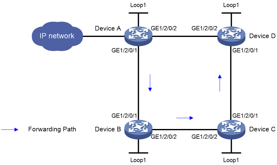
Network configuration
As shown in Figure 6, perform the following tasks on the devices to implement SRv6-TE policy-based forwarding over a specific path:
· Configure Device A through Device D to run IS-IS to implement Layer 3 connectivity.
· Configure basic SRv6 on Device A through Device D.
· Configure an SRv6-TE policy on Device A to forward user packets along path Device A > Device B > Device C > Device D.
|
Device |
Interface |
IP address |
Device |
Interface |
IP address |
|
Device A |
Loop1 |
1::1/128 |
Device B |
Loop1 |
2::2/128 |
|
|
GE1/2/0/1 |
1000::1/64 |
|
GE1/2/0/1 |
1000::2/64 |
|
|
GE1/2/0/2 |
4000::1/64 |
|
GE1/2/0/2 |
2000::2/64 |
|
Device C |
Loop1 |
3::3/128 |
Device D |
Loop1 |
4::4/128 |
|
|
GE1/2/0/1 |
3000::3/64 |
|
GE1/2/0/1 |
3000::4/64 |
|
|
GE1/2/0/2 |
2000::3/64 |
|
GE1/2/0/2 |
4000::4/64 |
Procedure
1. Configure IP addresses and masks for interfaces. (Details not shown.)
2. Configure Device A:
# Configure an SRv6 SID list.
[DeviceA] segment-routing ipv6
[DeviceA-segment-routing-ipv6] encapsulation source-address 1::1
[DeviceA-segment-routing-ipv6] locator a ipv6-prefix 5000:: 64 static 32
[DeviceA-segment-routing-ipv6-locator-a] opcode 1 end
[DeviceA-segment-routing-ipv6-locator-a] quit
[DeviceA-segment-routing-ipv6] traffic-engineering
[DeviceA-srv6-te] srv6-policy locator a
[DeviceA-srv6-te] segment-list s1
[DeviceA-srv6-te-sl-s1] index 10 ipv6 6000::1
[DeviceA-srv6-te-sl-s1] index 20 ipv6 7000::1
[DeviceA-srv6-te-sl-s1] index 30 ipv6 8000::1
[DeviceA-srv6-te-sl-s1] quit
# Create an SRv6-TE policy and set the attributes.
[DeviceA-srv6-te] policy p1
[DeviceA-srv6-te-policy-p1] binding-sid ipv6 5000::2
[DeviceA-srv6-te-policy-p1] color 10 end-point ipv6 4::4
# Configure a candidate path for the SRv6-TE policy and specify an explicit path (the SID list) for the candidate path.
[DeviceA-srv6-te-policy-p1] candidate-paths
[DeviceA-srv6-te-policy-p1-path] preference 10
[DeviceA-srv6-te-policy-p1-path-pref-10] explicit segment-list s1
[DeviceA-srv6-te-policy-p1-path-pref-10] quit
[DeviceA-srv6-te-policy-p1-path] quit
[DeviceA-srv6-te-policy-p1] quit
[DeviceA-srv6-te] quit
[DeviceA-segment-routing-ipv6] quit
# Configure IS-IS and set the IS-IS cost style to wide.
<DeviceA> system-view
[DeviceA] isis 1
[DeviceA-isis-1] network-entity 00.0000.0000.0001.00
[DeviceA-isis-1] cost-style wide
[DeviceA-isis-1] address-family ipv6 unicast
[DeviceA-isis-1-ipv6] segment-routing ipv6 locator a
[DeviceA-isis-1-ipv6] quit
[DeviceA-isis-1] quit
[DeviceA] interface gigabitethernet 1/2/0/1
[DeviceA-GigabitEthernet1/2/0/1] isis ipv6 enable 1
[DeviceA-GigabitEthernet1/2/0/1] quit
[DeviceA] interface gigabitethernet 1/2/0/2
[DeviceA-GigabitEthernet1/2/0/2] isis ipv6 enable 1
[DeviceA-GigabitEthernet1/2/0/2] quit
[DeviceA] interface loopback 1
[DeviceA-LoopBack1] isis ipv6 enable 1
[DeviceA-LoopBack1] quit
3. Configure Device B:
# Configure the SRv6 End.SID.
[DeviceB] segment-routing ipv6
[DeviceB-segment-routing-ipv6] locator b ipv6-prefix 6000:: 64 static 32
[DeviceB-segment-routing-ipv6-locator-b] opcode 1 end
[DeviceB-segment-routing-ipv6-locator-b] quit
[DeviceB-segment-routing-ipv6] quit
# Configure IS-IS and set the IS-IS cost style to wide.
<DeviceB> system-view
[DeviceB] isis 1
[DeviceB-isis-1] network-entity 00.0000.0000.0002.00
[DeviceB-isis-1] cost-style wide
[DeviceB-isis-1] address-family ipv6 unicast
[DeviceB-isis-1-ipv6] segment-routing ipv6 locator b
[DeviceB-isis-1-ipv6] quit
[DeviceB-isis-1] quit
[DeviceB] interface gigabitethernet 1/2/0/1
[DeviceB-GigabitEthernet1/2/0/1] isis ipv6 enable 1
[DeviceB-GigabitEthernet1/2/0/1] quit
[DeviceB] interface gigabitethernet 1/2/0/2
[DeviceB-GigabitEthernet1/2/0/2] isis ipv6 enable 1
[DeviceB-GigabitEthernet1/2/0/2] quit
[DeviceB] interface loopback 1
[DeviceB-LoopBack1] isis ipv6 enable 1
[DeviceB-LoopBack1] quit
4. Configure Device C:
# Configure the SRv6 End.SID.
[DeviceC] segment-routing ipv6
[DeviceC-segment-routing-ipv6] locator c ipv6-prefix 7000:: 64 static 32
[DeviceC-segment-routing-ipv6-locator-c] opcode 1 end
[DeviceC-segment-routing-ipv6-locator-c] quit
[DeviceC-segment-routing-ipv6] quit
# Configure IS-IS and set the IS-IS cost style to wide.
<DeviceC> system-view
[DeviceC] isis 1
[DeviceC-isis-1] network-entity 00.0000.0000.0003.00
[DeviceC-isis-1] cost-style wide
[DeviceC-isis-1] address-family ipv6 unicast
[DeviceC-isis-1-ipv6] segment-routing ipv6 locator c
[DeviceC-isis-1-ipv6] quit
[DeviceC-isis-1] quit
[DeviceC] interface gigabitethernet 1/2/0/1
[DeviceC-GigabitEthernet1/2/0/1] isis ipv6 enable 1
[DeviceC-GigabitEthernet1/2/0/1] quit
[DeviceC] interface gigabitethernet 1/2/0/2
[DeviceC-GigabitEthernet1/2/0/2] isis ipv6 enable 1
[DeviceC-GigabitEthernet1/2/0/2] quit
[DeviceC] interface loopback 1
[DeviceC-LoopBack1] isis ipv6 enable 1
[DeviceC-LoopBack1] quit
5. Configure Device D:
# Configure the SRv6 End.SID.
[DeviceD] segment-routing ipv6
[DeviceD-segment-routing-ipv6] locator d ipv6-prefix 8000:: 64 static 32
[DeviceD-segment-routing-ipv6-locator-d] opcode 1 end
[DeviceD-segment-routing-ipv6-locator-d] quit
[DeviceD-segment-routing-ipv6] quit
# Configure IS-IS and set the IS-IS cost style to wide.
<DeviceD> system-view
[DeviceD] isis 1
[DeviceD-isis-1] network-entity 00.0000.0000.0004.00
[DeviceD-isis-1] cost-style wide
[DeviceD-isis-1] address-family ipv6 unicast
[DeviceD-isis-1-ipv6] segment-routing ipv6 locator d
[DeviceD-isis-1-ipv6] quit
[DeviceD-isis-1] quit
[DeviceD] interface gigabitethernet 1/2/0/1
[DeviceD-GigabitEthernet1/2/0/1] isis ipv6 enable 1
[DeviceD-GigabitEthernet1/2/0/1] quit
[DeviceD] interface gigabitethernet 1/2/0/2
[DeviceD-GigabitEthernet1/2/0/2] isis ipv6 enable 1
[DeviceD-GigabitEthernet1/2/0/2] quit
[DeviceD] interface loopback 1
[DeviceD-LoopBack1] isis ipv6 enable 1
[DeviceD-LoopBack1] quit
Verifying the configuration
# Display SRv6-TE policy information on Device A.
[DeviceA] display segment-routing ipv6 te policy
Name/ID: p1/0
Color: 10
Endpoint: 4::4
BgpName: <none>
BSID:
Mode: Explicit Type: Type_2 Request state: Succeeded
Current BSID: 5000::2 Explicit BSID: 5000::2 Dynamic BSID: -
Reference counts: 4
Flags: A/BS/NC
Status: Up
Up time: 2020-04-02 16:08:03
Down time: 2020-04-02 16:03:48
Statistics: Not configured
Forwarding index: 2150629377
Candidate paths state: Configured
Candidate paths statistics:
CLI paths: 1 BGP paths: 0 PCEP paths: 0
Candidate paths:
Preference : 10
CPathName: <none>
Instance ID: 0 ASN: 0 Node address: 0.0.0.0
Peer address: ::
Optimal: Y Flags: V/A
Explicit SID list:
ID: 1 Name: s1
Weight: 1 Forwarding index: 2149580801
State: Up
The output shows that the SRv6-TE policy is in up state. The device can use the SRv6-TE policy to forward packets.
# Display SRv6 TE forwarding information on Device A.
[DeviceA] display segment-routing ipv6 te forwarding verbose
Total forwarding entries: 1
Policy name/ID: p1/0
Binding SID: 5000::2
Policy forwarding index: 0x80300001
Main path:
Seglist ID: 1
Seglist forwarding index: 0x80200001
Weight: 1
Outgoing forwarding index: 0x80100001
Interface: GE1/2/0/1
Nexthop: FE80::54CB:70FF:FE86:316
Path ID: 0
SID list: {6000::1, 7000::1, 8000::1}
# Display SRv6 forwarding information on Device A.
[DeviceA] display segment-routing ipv6 forwarding
Total SRv6 forwarding entries: 3
Flags: T - Forwarded through a tunnel
N - Forwarded through the outgoing interface to the nexthop IP address
A - Active forwarding information
B - Backup forwarding information
ID Flags Forwarding info
--------------------------------------------------------------------------------
2148532225 NA GE1/2/0/1
FE80::54CB:70FF:FE86:316
{6000::1, 7000::1, 8000::1}
2149580801 TA 2148532225
2150629377 TA 2149580801
