- Table of Contents
- Related Documents
-
| Title | Size | Download |
|---|---|---|
| 01-IPv6 Segment Routing configuration | 531.11 KB |
Configuring IPv6 Segment Routing
SR microloop avoidance after a network failure
SR microloop avoidance after a failure recovery
Using IGP to advertise SRv6 SIDs
Configuring MPLS L3VPN over SRv6
MPLS L3VPN over SRv6 tasks at a glance
Adding an End.DT4 or End.DT6 SID to the routes of a VPN instance
Configuring PEs to exchange BGP VPNv4 or VPNv6 routes
Configuring IPv6 peers to exchange End.DT4 or End.DT6 SIDs
Configuring BGP VPNv4 or VPNv6 routes
Specifying a source address for the outer IPv6 header of SRv6-encapsulated MPLS L3VPN packets
Enabling the SID-route-recursion feature
Enabling SRv6 VPN compatibility with a peer or peer group
Configuring EVPN L3VPN over SRv6
EVPN L3VPN over SRv6 tasks at a glance
Adding an End.DT4 or End.DT6 SID to the routes of a VPN instance
Configuring SRv6-encapsulated EVPN route advertisement
Configuring PEs to exchange BGP EVPN routes
Specifying a source address for the outer IPv6 header of SRv6-encapsulated EVPN L3VPN packets
Enabling the SID-route-recursion feature
Disabling an interface from participating in TI-LFA calculation
Configuring SR microloop avoidance
Display and maintenance commands for SRv6
Displaying and maintaining the running status of SRv6
Displaying and maintaining the running status of SRv6 VPN
Example: Configuring IPv6 IS-IS TI-LFA FRR
Example: Configuring MPLS L3VPN over SRv6
Configuring IPv6 Segment Routing
About IPv6 Segment Routing
Segment Routing (SR) is a source routing technology. The source node selects a path for packet forwarding, and then encodes the path in the packet header as an ordered list of segments. Each segment is identified by the Segment Identifier (SID). The SR nodes along the path forward the packets based on the SIDs in the packets. Only the source node needs to maintain the path status.
IPv6 Segment Routing (SRv6) uses IPv6 addresses as SIDs to forward packets.
Basic concepts
SR node
An SR node is a node that supports the SRv6 feature. The ingress node (source node) selects a path for packet forwarding, encodes the path as an ordered SID list in the routing extension header. The transit nodes forward the packets based on the SID list. The egress node removes the routing extension header and forwards the packets to the destination.
SID
SRv6 supports the following types of SIDs:
· IPv6 address of an interface.
· SRv6 SID that has a specific function.
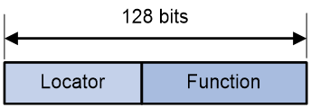
An SRv6 SID is in the format of IPv6 address, but the IPv6 address does not belong to any interface on any device.
As shown in Figure 1, an SRv6 SID contains the Locator and Function (Opcode) portions.
· Locator—Contains a locator that identifies the routing capability. The locator of an SRv6 SID must be unique in the SR domain.
· Function—Contains an opcode that identifies the network function of an SR node, for example, forwarding packets and performing specific services. An SR node will execute the function in the SRv6 SID Function field of an SRv6 packet after it receives that SRv6 packet.
According to the functions of SRv6 SIDs, SRv6 SIDs are divided into the following categories:
· End SID—Identifies the prefix of a destination address in the network.
· End.X SID—Identifies a link in the network.
· End.DT4 SID—Identifies an IPv4 VPN in the network.
· End.DT6 SID—Identifies an IPv6 VPN in the network.
· End.OP SID—Applies to the SRv6 OAM scenario. For more information about End.OP SIDs, see "Configuring SRv6 OAM."
Use IGP to advertise SRv6 SIDs for an SR node. The other SR nodes will generate route entries of that SR node based on the advertised information.
Local SID forwarding table
An SRv6-enabled node maintains a local SID forwarding table that records the SRv6 SIDs generated on the local node. The local SID forwarding table has the following functions:
· Stores local generated SRv6 SID forwarding information.
· Stores SRv6 SID operation types.
Segment List
A Segment List is an ordered list of SIDs, which is also referred to as a Segment Identifier (SID) list in this document. The SR nodes forward packets based on the SIDs in the order that they are arranged in the SID list.
SRv6 tunnel
An SRv6 tunnel is a virtual point-to-point connection established between the SRv6 ingress node and egress node. IPv6 packets are encapsulated at the ingress node and de-encapsulated at the egress node.
SRv6 packet format
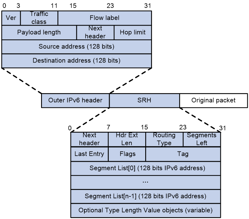
An outer IPv6 header and a Segment Identifier Header (SRH) are added to the original Layer 3 data packet to form an SRv6 packet.
As shown in Figure 2, the value for the Next Header field is 43 in the outer IPv6 header, which indicates that the header next to the IPv6 header is a routing extension header. The value for the Routing Type field in the routing extension header is 4, which indicates that the routing extension header is an SRH. The SRH header contains the following fields:
· 8-bit Next Header—Identifies the type of the header next to the SRH.
· 8-bit Hdr Ext Len—Length of the SRH header in 8-octet units, not including the first 8 octets.
· 8-bit Routing Type—The value for this field is 4, which represents SRH.
· 8-bit Segments Left—Contains the index of the next segment to inspect in the Segment List. The Segments Left field is set to n-1 where n is the number of segments in the Segment List. Segments Left is decremented at each segment.
· 8-bit Last Entry—Contains the index of the first SID in the path used to forward the packet.
· 8-bit Flags—Contains flags.
· 16-bit Tag—Tags a packet as part of a class or group of packets, for example, packets sharing the same set of properties.
· Segment List—Contains 128-bit IPv6 addresses representing the ordered segments. The Segment List is encoded starting from the last segment of the path. The first element of the segment list (Segment List [0]) contains the last segment of the path, the second element (Segment List [1]) contains the penultimate segment of the path and so on. The number enclosed in a pair of brackets is the index of a segment.
SRv6 packet forwarding
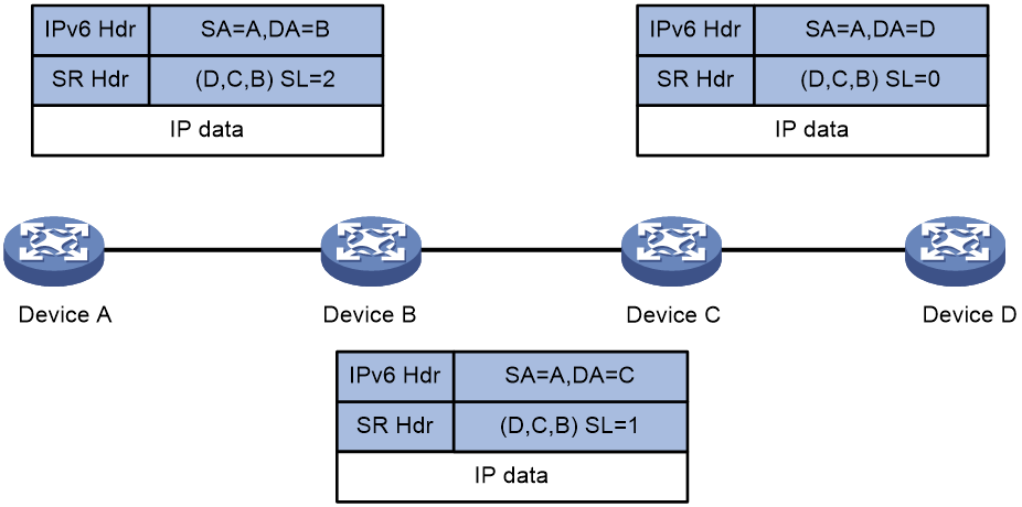
As shown in Figure 3, an IPv6 packet is forwarded through an SRv6 tunnel as follows:
1. Upon receiving an IPv6 packet, Device A finds in the routing table that the outgoing interface is an SRv6 tunnel interface. The packet is delivered to the tunnel interface.
2. The SRv6 tunnel interface encapsulates the IPv6 packet as follows:
¡ Adds an SRH header. The Segments Left (SL) value is the number of segments minus one. The path from ingress to egress has three segments, so the SL value is set to 2. The encapsulated SID list is Segment List [0]=D, Segment List [1]=C, Segment List [2]=B. The Segment List is encoded starting from the last segment of the path to the first segment of the path.
¡ Adds an outer IPv6 header. The source address is the tunnel source, and the destination address is determined by the SL value. On Device A, the SL value is 2, which points to the IPv6 address of Device B, so the destination address is the IPv6 address of Device B.
3. Device A searches the routing table for the destination address in the newly encapsulated IPv6 header, and forwards the packet to Device B.
4. Device B first checks the destination address and SID type in the outer IPv6 header.
¡ If the SID type is End.X, the device obtains the output interface and next hop information based on the End.X SID.
¡ If the SID is not End.X, the device does not perform any operation.
Then, the device checks the SL value in the SRH header and decreases the value by one. Then, the device searches for the IPv6 address pointed by Segment List [1] and uses the IPv6 address of Device C to replace the destination address of the outer IPv6 header.
5. Device B performs one of the following operations depending on the SID type:
¡ For an End.X SID, the device forwards the encapsulated packet to Device C based on the obtained output interface and next hop information.
¡ For an SID of the other type, the device searches the routing table for the destination address in the outer IPv6 header and forwards the packet to Device C.
6. Device C performs the same operations as what Device B has done in steps 4 and 5, and then forwards the packet to Device D.
7. Device D checks the SL value in the SRH header and finds that the value has decreased to 0. The device performs the following operations:
a. De-encapsulates the packet by removing the outer IPv6 header and the SRH header.
b. Forwards the original IP data packet to the destination based on the destination address.
Figure 3 SRv6 tunnel packet forwarding
MPLS L3VPN over SRv6
MPLS L3VPN over SRv6 is an SRv6 VPN technology. This technology advertises IPv4 or IPv6 VPN routes to remote sites over the IPv6 backbone network and transmits IPv4 or IPv6 VPN traffic in SRv6 encapsulation to the remote sites.
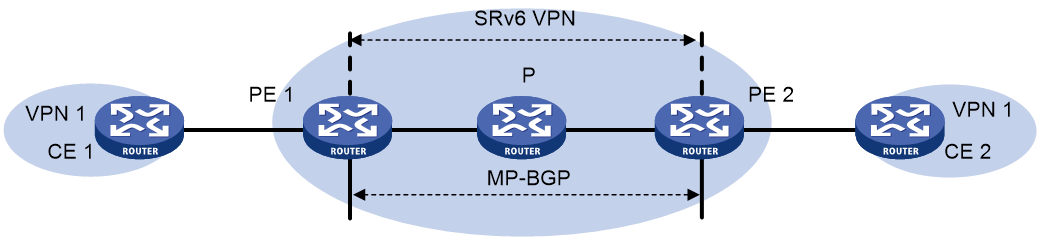
Figure 4 shows a typical MPLS L3VPN over SRv6 network.
· PE 1 and PE 2 use MP-BGP to advertise IPv4 or IPv6 VPN routes to each other over the IPv6 backbone network. The VPN routes contain private network routing information and SID information.
· The PEs have a single-hop SRv6 tunnel between them and they use the SRv6 tunnel to forward VPN traffic across sites.
· The devices in the IPv6 backbone network forward the SRv6-encapsulated VPN traffic through the optimal path calculated by IGP.
MPLS L3VPN over SRv6 connects geographically dispersed sites that belong to the same VPN over the IPv6 backbone network.

Route advertisement
The route advertisement process of IPv4 MPLS L3VPN over SRv6 is similar to that of IPv6 MPLS L3VPN over SRv6. This section uses IPv4 MPLS L3VPN over SRv6 to illustrate the process.
As shown in Figure 4, local routes of CE 1 are advertised to CE 2 by using the following process:
1. CE 1 uses static routing, RIP, OSPF, IS-IS, EBGP, or IBGP to advertise routes of the local site to PE 1.
2. After learning the route information of CE 1, PE 1 stores the routes to the routing table of VPN 1. In addition, PE 1 converts the routes to VPNv4 routes by adding an RD and RT and assigning an End.DT4 SID as the private network label to the routes. Then, PE 1 advertises the VPNv4 routes to PE 2 by using MP-BGP.
3. PE 2 adds the VPNv4 routes to the routing table of VPN 1, converts the VPNv4 routes to IPv4 routes, and advertises the IPv4 routes to CE 2.
4. By adding the received IPv4 routes to the routing table, CE 2 learns the private network routes of CE 1.
Packet forwarding
The packet forwarding process of IPv4 MPLS L3VPN over SRv6 is similar to that of IPv6 MPLS L3VPN over SRv6. This section uses IPv4 MPLS L3VPN over SRv6 to illustrate the process.
As shown in Figure 4, CE 2 forwards an IPv4 packet to CE 1 as follows:
1. CE 2 sends the IPv4 packet to PE 2.
2. PE 2 receives the packet on an interface associated with VPN 1. PE 2 searches for a route that matches the destination IPv4 address of the packet in the routing table of VPN 1. The corresponding End.DT4 SID is found. Then, PE 2 encapsulates an outer IPv6 header for the packet. The End.DT4 SID is encapsulated in the outer IPv6 header as the destination address.
3. PE 2 searches the IPv6 routing table based on the End.DT4 SID for the optimal IGP route and forwards the packet to P through the optimal IGP route.
4. P searches the IPv6 routing table based on the End.DT4 SID for the optimal IGP route and forwards the packet to PE 1 through the optimal IGP route.
5. PE 1 searches the local SID forwarding table for the End.DT4 SID and performs the following operations:
a. Removes the outer IPv6 header.
b. Matches the packet to VPN 1 based on the End.DT4 SID, and searches the routing table of VPN 1 for the optimal route.
c. Forwards the packet to CE 1.
EVPN L3VPN over SRv6
EVPN L3VPN over SRv6 is an SRv6 VPN technology. This technology advertises IPv4 or IPv6 BGP EVPN routes to remote sites over the IPv6 backbone network and transmits EVPN L3VPN traffic in SRv6 encapsulation to the remote sites.
Figure 5 shows a typical EVPN L3VPN over SRv6 network.
· PE 1 and PE 2 use MP-BGP to advertise EVPN IP advertisement routes to each other over the IPv6 backbone network. The EVPN IP advertisement routes contain IPv4 or IPv6 VPN routing information and SID information.
· The PEs have a single-hop SRv6 tunnel between them and they use the SRv6 tunnel to forward EVPN L3VPN traffic across sites.
· The devices in the IPv6 backbone network forward the SRv6-encapsulated EVPN L3VPN traffic through the optimal path calculated by IGP.
EVPN L3VPN over SRv6 connects geographically dispersed sites that belong to the same VPN over the IPv6 backbone network.
Route advertisement
The route advertisement process of IPv4 EVPN L3VPN over SRv6 is similar to that of IPv6 EVPN L3VPN over SRv6. This section uses IPv4 EVPN L3VPN over SRv6 to illustrate the process.
As shown in Figure 5, local routes of CE 1 are advertised to CE 2 by using the following process:
1. CE 1 uses static routing, RIP, OSPF, IS-IS, EBGP, or IBGP to advertise routes of the local site to PE 1.
2. PE 1 stores the routes advertised by CE 1 to the routing table of VPN 1. In addition, PE 1 converts the routes to BGP EVPN IP advertisement routes by adding RD and RT attributes and assigning an End.DT4 SID as the private network label to the routes. Then, PE 1 advertises the IP advertisement routes to PE 2 by using MP-BGP.
3. PE 2 adds the IP advertisement routes to the routing table of VPN 1, converts the IP advertisement routes to IPv4 routes, and advertises the IPv4 routes to CE 2.
4. By adding the received IPv4 routes to the routing table, CE 2 learns the private network routes of CE 1.
Packet forwarding
The packet forwarding process of IPv4 EVPN L3VPN over SRv6 is similar to that of IPv6 EVPN L3VPN over SRv6. This section uses IPv4 EVPN L3VPN over SRv6 to illustrate the process.
As shown in Figure 5, CE 2 forwards an IPv4 packet to CE 1 as follows:
1. CE 2 sends the IPv4 packet to PE 2.
2. PE 2 receives the packet on an interface associated with VPN 1. PE 2 searches for a route that matches the destination IPv4 address of the packet in the routing table of VPN 1. The corresponding End.DT4 SID is found. Then, PE 2 encapsulates an outer IPv6 header for the packet. The End.DT4 SID is encapsulated in the outer IPv6 header as the destination address.
3. PE 2 searches the IPv6 routing table based on the End.DT4 SID for the optimal IGP route and forwards the packet to P through the optimal IGP route.
4. P searches the IPv6 routing table based on the End.DT4 SID for the optimal IGP route and forwards the packet to PE 1 through the optimal IGP route.
5. PE 1 searches the local SID forwarding table for the End.DT4 SID and performs the following operations:
a. Removes the outer IPv6 header.
b. Matches the packet to VPN 1 based on the End.DT4 SID, and searches the routing table of VPN 1 for the optimal route.
c. Forwards the packet to CE 1.
TI-LFA FRR
Topology-Independent Loop-Free Alternate Fast Re-Route (TI-LFA FRR) provides link and node protection for SRv6 tunnels. When a link or node fails, TI-LFA FRR switches the traffic to the backup path to ensure continuous data forwarding.
TI-LFA FRR background
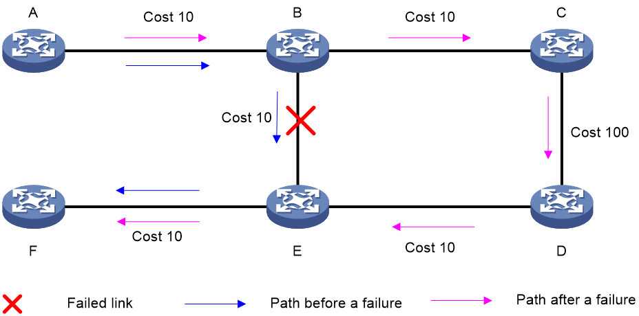
As shown in Figure 6, node A sends data packets to node F. When the link between node B and node E fails, node B forwards the data packets to node C. The cost of the link between node C and node D is 100 (which is greater than the cost of the link between node C and node D) and the routes on node C have not converged. As a result, node C determines that the next hop of the optimal path to reach node F is node B. Then, node C forwards the data packets back to node B, which causes a loop.
Figure 6 TI-LFA application scenario

To resolve this issue, deploy TI-FLA on the SRv6 network. As shown in Figure 7, when the link between node B and node E fails, node B uses the backup path calculated by TI-LFA to forward the data packets along the B->C->D->E path.
Figure 7 TI-LFA forwarding network diagram
TI-LFA FRR concepts
· P space—Use the source node of the protected link as the root to establish a shortest path tree. All nodes that are reachable from the source node without passing the protected link form the P space. Nodes in the P space are called P nodes.
· Extended P space—Use the source node of the protected link and its neighbors as the roots to establish shortest path trees. All nodes that are reachable from the source node or one of its neighbors without passing the protected link form the extended P space. The P space is a subset of the extended P space.
· Q space—Use the destination node of the protected link as the root to establish a reverse shortest path tree. All nodes that are reachable from the root node without passing the protected link form the Q space. Nodes in the Q space are called Q nodes.
· Repair list—A constraint path used to indicate how a P node reaches a Q node when the P space and Q space do not have common nodes. The repair list contains the following SRv6 SIDs:
¡ SRv6 SIDs of P nodes.
¡ SRv6 SIDs from P nodes to nearest Q nodes.
TI-LFA FRR protection types
The following TI-LFA traffic protection types are available:
· Link protection—Protects traffic that traverses a specific link.
· Node protection—Protects traffic that traverses a specific node.
Node protection takes precedence over link protection.
TI-LFA FRR path calculation
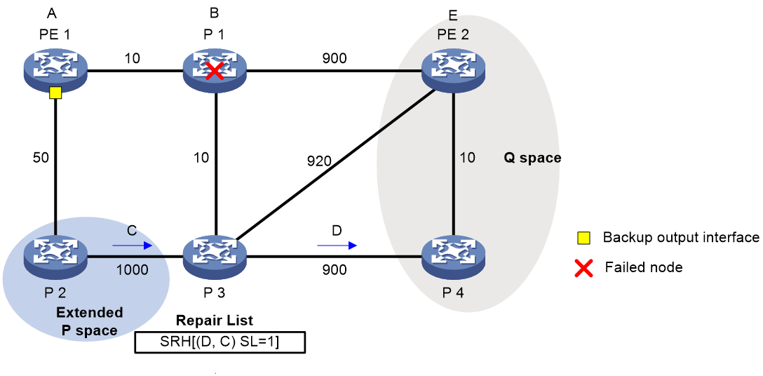
As shown in Figure 8, PE 1 is the source node. P 1 is the faulty node. PE 2 is the destination node. The numbers on links represent the link costs. A data flow traverses PE 1, P 1, and PE 2. To protect data against P 1 failure, TI-LFA FRR calculates the extended P space, Q space, shortest path tree converged after P 1 fails, repair list, and backup output interface, and creates the backup forwarding entry.
TI-LFA FRR calculates the backup path by using the following steps:
1. Calculates the extended P space: P 2.
2. Calculates the Q space: PE 2 and P 4.
3. Calculates the shortest path tree converged after P 1 fails: PE 1 --> P 2 --> P 4 --> PE 2.
4. Calculates the repair list: End.X SID C of the link between P 2 and P 3 and End.X SID D of the link between P 3 and P 4.
5. Calculates the backup output interface, that is, the output interface to the next hop after the link from PE 1 to P 1 fails.
TI-LFA FRR forwarding process
After TI-LFA FRR finishes backup path calculation, traffic will be switched to the backup path in response to a primary path failure.
As shown in Figure 9, P 2 is a P node and P 4 and PE 2 are Q nodes. When the next hop on the primary path (P 1) fails, TI-LFA FRR switches the traffic to the backup path. The following are the detailed steps:
1. PE 1 looks up the IPv6 routing table for the destination IPv6 address of a packet and finds that the next hop is P 2. PE 1 encapsulates the packet according to the repair list.
¡ Adds an SRH header. The SID list is Segment List [0]=D and Segment List [1]=C. The SIDs are arranged from the farthest node to the nearest node.
¡ Adds an outer IPv6 header. The source address is address A on source node PE 1 and the destination address is the address pointed by SL. Because the SL is 1, the destination address is C as pointed by Segment List [1].
2. After P2 receives the packet, it performs the following operations:
a. Checks the SL value in the SRH header and decreases the value by 1.
b. Searches for the address pointed by Segment List [0] and finds that the address is End.X SID D between P 3 and P 4.
c. Replaces the destination address in the outer IPv6 header with End.X SID D.
d. Obtains the output interface and next hop according to End.X SID C and forwards the encapsulated packet to P 3.
3. After P3 receives the packet, it performs the following operations:
a. Checks the SL value in the SRH header and finds that the SL value is 0.
b. Decapsulates the packet.
c. Obtains the output interface and next hop according to End.X SID D and forwards the packet to P 4.
4. After P4 receives the packet, it searches the IP routing table for the destination IP address of the packet and forwards the packet to PE 2.
Figure 9 Data forwarding over the TI-LFA FRR backup path

SR microloop avoidance after a network failure
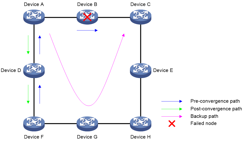
As shown in Figure 10, when Device B fails, traffic to Device C will be switched to the backup path calculated by TI-LFA. After Device A finishes route convergence, traffic will be switched to the post-convergence path. If Device D and Device F have not finished route convergence and still forward traffic along the pre-convergence path, a loop is formed between Device A and Device F. The loop exists until Device D and Device F finish route convergence.
SR microloop avoidance can resolve this issue. After you configure TI-LFA, Device A first switches traffic to the backup path calculated by TI-LFA when Device B fails. Then, Device A waits for Device D and Device F to finish route convergence before starting route convergence. After Device A also finishes route convergence, Device A switches the traffic to the converged route.
Figure 10 Diagram for SR microloop avoidance after a network failure
SR microloop avoidance after a failure recovery
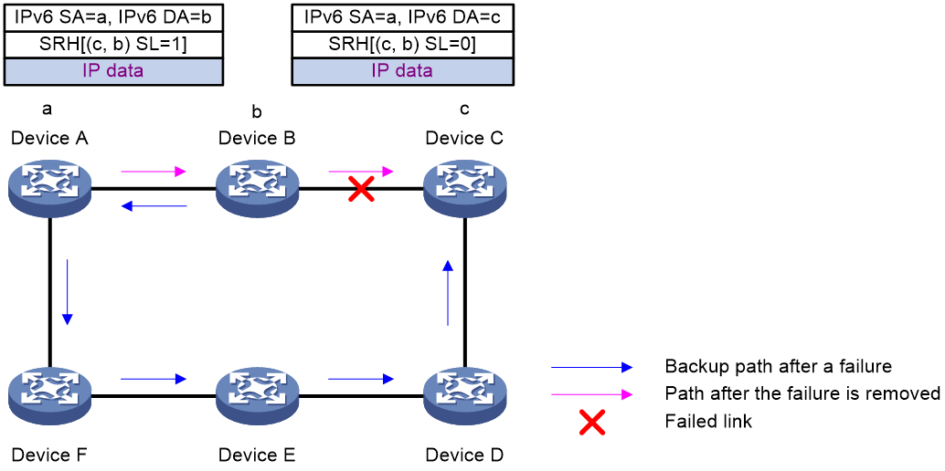
As shown in Figure 11, before the link between Device B and Device C recovers, traffic traverses along the backup path. After the link recovers, Device A forwards the traffic to Device B if Device A finishes route convergence before Device B. With route convergence unfinished, Device B still forwards the traffic along the backup path. A loop is formed between Device A and Device B.
SR microloop avoidance can resolve this issue. After the link recovers, SR microloop avoidance automatically calculates the optimal path from Device A to Device C and forwards traffic along the path. To forward a packet along the newly calculated path, Device A adds, for example, the adjacency SID from Device B to Device C, to the packet and then sends the packet to Device B. Then, Device B forwards the packet to Device C based on the path information.
Upon expiration of the microloop avoidance RIB-update-delay timer and completion of route convergence on Device B, Device A does not add path information to packets anymore. It will forward packets to Device C as usual.
Figure 11 Diagram for SR microloop avoidance after a failure recovery
Protocols and standards
· draft-previdi-6man-segment-routing-header
· draft-ietf-6man-segment-routing-header
· draft-filsfils-spring-segment-routing
· draft-filsfils-spring-srv6-network-programming
SRv6 tasks at a glance
To configure SRv6, perform the following tasks:
This task is required if you use SRv6 SIDs to set up routing and forwarding table entries.
2. Using IGP to advertise SRv6 SIDs
This task is required if you use SRv6 SIDs to set up routing and forwarding table entries.
3. Configuring MPLS L3VPN over SRv6
This task is required if you plan to advertise VPN routes over the IPv6 backbone network and transmit VPN traffic in SRv6 encapsulation to remote sites.
4. Configuring EVPN L3VPN over SRv6
This task is required if you plan to advertise VPN routing information in EVPN routes over the IPv6 backbone network and transmit EVPN L3VPN traffic in SRv6 encapsulation to remote sites.
5. (Optional.) Configuring TI-LFA FRR
Prerequisites for SRv6
Before you configure an SRv6 tunnel, perform the following tasks:
· Determine the ingress node, transit nodes, and egress node of the SRv6 tunnel.
· Plan the IPv6 address of each SR node.
Configuring an SRv6 SID
About this task
An SRv6 SID is in the format of IPv6 address and it contains 128 bits. An SRv6 SID contains the Locator, Function, and Args portions.
· The Locator portion is determined by the ipv6-prefix ipv6-address prefix-length parameter. The portion length is determined by the prefix-length argument. A locator is an IPv6 subnet. All IPv6 addresses in the subnet can be used as SRv6 SIDs.
· The Function portion contains an opcode. The opcode can be a static opcode or a dynamic opcode.
¡ Static opcode—Manually configured by using the opcode command. SRv6 SIDs generated based on a static opcode are static SRv6 SID. The length of a static opcode is determined by the static static-length option, and it determines the number of static SRv6 SIDs on the locator.
¡ Dynamic opcode—Dynamically allocated by IGP. SRv6 SIDs generated based on a dynamic opcode are dynamic SRv6 SID. When dynamically allocating SRv6 SIDs, IGP applies for SIDs outside the static opcode range to avoid SRv6 SID conflicts.
· The Args portion contains traffic flow and service information. This portion is determined by the args args-length option.
The length of a dynamic opcode is calculated by using the following formula: dynamic-length = 128 - (prefix-length + static-length + args-length).
A static SRv6 SID is generated based on the following formula: static SRv6 SID = ipv6-prefix + 0 + opcode + 0.
· The ipv6-prefix portion represents the IPv6 prefix specified by using theipv6-address and prefix-length arguments in the locator command. The number of bits occupied by the IPv6 prefix is configured by using the prefix-length argument.
· The number of bits occupied by 0s (following the ipv6-prefix portion) is the value of the dynamic-length argument.
· The opcode portion represents the opcode. The number of bits occupied by the opcode is configured by using the static-length argument in the locator command.
· The number of bits occupied by 0s (following the opcode portion) is the value of the args-length argument.
A dynamic SRv6 SID is generated based on the following formula: dynamic SRv6 SID = ipv6-prefix + dynamic + 0.
· The ipv6-prefix portion represents the IPv6 prefix specified by using the ipv6-address and prefix-length arguments in the locator command. The number of bits occupied by the IPv6 prefix is configured by using the prefix-length argument.
· The dynamic portion is dynamically allocated by IGP. The number of bits occupied by this portion is the value of the dynamic-length argument.
· The number of bits occupied by 0s is the sum value of the static-length and args-length arguments.
For example, in the locator test1 ipv6-prefix 100:200:DB8:ABCD:: 64 static 24 args 32 command:
· The Locator portion is 100:200:DB8:ABCD::. This portion occupies 64 bits.
· The static opcode occupies 24 bits.
· The Args portion occupies 32 bits.
· The dynamic opcode occupies 8 bits.
The static SRv6 SID range and dynamic SRv6 SID range are as follows:
· The start static SRv6 SID is 100:200:DB8:ABCD:0:1::.
· The end static SRv6 SID is 100:200:DB8:ABCD:FF:FFFF::.
· The start dynamic SRv6 SID is 100:200:DB8:ABCD:100::.
· The end dynamic SRv6 SID is 100:200:DB8:ABCD:FFFF:FFFF::.
Restrictions and guidelines
Each locator must have a unique name.
Do not configure the same IPv6 address prefix and prefix length for different locators. In addition, the IPv6 address prefixes of different locators cannot overlap.
Procedure
1. Enter system view.
system-view
2. Enable SRv6 and enter SRv6 view.
segment-routing ipv6
3. Configure a locator and enter SRv6 locator view.
locator locator-name [ ipv6-prefix ipv6-address prefix-length [ args args-length | static static-length ] * ]
4. Configure an opcode. Perform one of the following tasks:
¡ Configure an End SID.
opcode opcode end
¡ Configure an End.X SID.
opcode opcode end-x interface interface-type interface-number nexthop nexthop-address
¡ Configure an End.DT4 SID.
opcode opcode end-dt4 vpn-instance vpn-instance-name [ evpn ]
The specified VPN instance must exist. The same End.DT4 SID cannot be configured in different VPN instances.
¡ Configure an End.DT46 SID.
opcode opcode end-dt46 vpn-instance vpn-instance-name [ evpn ]
The specified VPN instance must exist. An End.DT46 SID cannot be configured in different VPN instances.
¡ Configure an End.DT6 SID.
opcode opcode end-dt6 vpn-instance vpn-instance-name [ evpn ]
The specified VPN instance must exist. An End.DT6 SID cannot be configured in different VPN instances.
¡ Configure an End.OP SID.
opcode opcode end-op
Using IGP to advertise SRv6 SIDs
About this task
Use an IGP protocol to advertise the SRv6 SID of a locator by applying the locator to the IGP protocol.
Prerequisites
If IS-IS is used to advertise SRv6 SIDs, make sure the cost style of IS-IS is wide, compatible, or wide-compatible. For more information about the cost styles of IS-IS, see Layer 3—IP Routing Configuration Guide.
Using IS-IS to advertise SRv6 SIDs
1. Enter system view.
system-view
2. Enter IS-IS process view.
isis [ process-id ] [ vpn-instance vpn-instance-name ]
3. Enter IS-IS IPv6 address family view.
address-family ipv6 [ unicast ]
4. Apply a locator to IS-IS IPv6 address family.
segment-routing ipv6 locator locator-name [ level-1 | level-2 ] [ auto-sid-disable ]
By default, no locators are applied to IS-IS IPv6 address family.
Repeat this command to apply multiple locators to IS-IS IPv6 address family for the family to advertise multiple SRv6 SIDs.
Using OSPFv3 to advertise SRv6 SIDs
1. Enter system view.
system-view
2. Enter OSPFv3 process view.
ospfv3 [ process-id | vpn-instance vpn-instance-name ] *
3. Apply a locator to the OSPFv3 process.
segment-routing ipv6 locator locator-name
By default, no locators are applied to an OSPFv3 process.
Repeat this command to apply multiple locators to the OSPFv3 process for the process to advertise multiple SRv6 SIDs.
Configuring MPLS L3VPN over SRv6
MPLS L3VPN over SRv6 tasks at a glance
To configure MPLS L3VPN over SRv6, perform the following tasks:
1. Configuring a VPN instance
Perform this task on PEs. For more information, see MPLS L3VPN in MPLS Configuration Guide.
2. Configuring route exchange between a PE and a CE
a. Configuring an IPv4 routing protocol (static routing, RIP, OSPF, IS-IS, EBGP, or IBGP) or an IPv6 routing protocol (IPv6 static routing, RIPng, OSPFv3, IPv6 IS-IS, EBGP, or IBGP) to exchange routes between a PE and a CE
On the CE, configure an IPv4 or IPv6 routing protocol to advertise routes of the local site to the PE. On the PE, associate the routing protocol with the VPN instance. For more information about routing protocol configurations, see Layer 3—IP Routing Configuration Guide.
b. Adding an End.DT4 or End.DT6 SID to the routes of a VPN instance
Perform this task to enable the PE to add an End.DT4 or End.DT6 SID as the private network label to the routes of a VPN instance.
3. Configuring route exchange between PEs
a. Configuring PEs to exchange BGP VPNv4 or VPNv6 routes
b. Configuring IPv6 peers to exchange End.DT4 or End.DT6 SIDs
This feature enables PEs to exchange End.DT4 or End.DT6 SIDs through BGP VPNv4 or VPNv6 routes.
c. (Optional.) Configuring BGP VPNv4 or VPNv6 routes
4. Specifying a source address for the outer IPv6 header of SRv6-encapsulated MPLS L3VPN packets
This feature specifies the source address of the outer IPv6 header for SRv6 packets that are delivered between two private network sites over the backbone network.
This feature specifies the destination address (End.DT4 or End.DT6 SID) of the outer IPv6 header for SRv6 packets that are delivered between two private network sites over the backbone network.
6. Enabling the SID-route-recursion feature
This feature enables a PE to perform route recursion for private network routes. The private network routes of a VPN instance recurse to IPv6 routes destined for the End.DT4 or End.DT6 SID associated with that VPN instance. Then, the PE can select the optimal path calculated by IGP to forward private network traffic over the IPv6 backbone network.
7. (Optional.) Enabling SRv6 VPN compatibility with a peer or peer group
Adding an End.DT4 or End.DT6 SID to the routes of a VPN instance
About this task
In an MPLS L3VPN over SRv6 network, the private network routes of a VPN instance advertised by a PE through BGP update messages must have an End.DT4 or End.DT6 SID. This End.DT4 or End.DT6 SID is used to identify packets that belong to the VPN instance. You can specify the End.DT4 or End.DT6 SID in the BGP-VPN IPv4 or IPv6 unicast address family of the VPN instance.
Restrictions and guidelines
The VPN instance of the specified locator must be the same as the VPN instance of the private network. To specify a VPN instance for a locator, use the opcode end-dt4 or opcode end-dt6 command in SRv6 locator view.
Prerequisites
Before you perform this task, you must create the specified locator.
Procedure
1. Enter system view.
system-view
2. Enter BGP instance view.
bgp as-number [ instance instance-name ]
3. Enter BGP-VPN instance view.
ip vpn-instance vpn-instance-name
4. Enter BGP-VPN IPv4 unicast address family view or BGP-VPN IPv6 unicast address family view.
¡ Enter BGP-VPN IPv4 unicast address family view.
address-family ipv4 [ unicast ]
¡ Enter BGP-VPN IPv6 unicast address family view.
address-family ipv6 [ unicast ]
5. Add the SID attribute to private network routes when the routes are converted to VPNv4 or VPNv6 routes.
segment-routing ipv6 locator locator-name [ auto-sid-disable ]
By default, the SID attribute is not add to private network routes when the routes are converted to VPNv4 or VPNv6 routes.
Configuring PEs to exchange BGP VPNv4 or VPNv6 routes
Restrictions and guidelines
For more information about the commands in this section, see BGP in Layer 3—IP Routing Command Reference.
Procedure
1. Enter system view.
system-view
2. Enter BGP instance view.
bgp as-number [ instance instance-name ]
3. Specify a remote PE as an IPv6 peer.
peer { group-name | ipv6-address [ prefix-length ] } as-number as-number
4. Specify a source interface (IPv6 address) for establishing TCP connections to an IPv6 peer or peer group.
peer { group-name | ipv6-address [ prefix-length ] } connect-interface interface-type interface-number
By default, BGP uses the output interface in the optimal route destined for a BGP peer or peer group as the source interface for establishing TCP connections.
5. Create the BGP VPNv4 or VPNv6 address family and enter its view.
¡ Create the BGP VPNv4 address family and enter its view.
address-family vpnv4
¡ Create the BGP VPNv6 address family and enter its view.
address-family vpnv6
6. Enable BGP to exchange VPNv4 or VPNv6 routing information with an IPv6 peer or peer group.
peer { group-name | ipv6-address [ prefix-length ] } enable
By default, BGP cannot exchange VPNv4 or VPNv6 routing information with an IPv6 peer or peer group.
Configuring IPv6 peers to exchange End.DT4 or End.DT6 SIDs
About this task
Perform this task to configure IPv6 peers to exchange End.DT4 or End.DT6 SID information through BGP VPNv4 or VPNv6 routes.
Procedure
1. Enter system view.
system-view
2. Enter BGP instance view.
bgp as-number [ instance instance-name ]
3. Enter BGP VPNv4 address family view or BGP VPNv6 address family view.
¡ Enter BGP VPNv4 address family view.
address-family vpnv4
¡ Enter BGP VPNv6 address family view.
address-family vpnv6
4. Enable BGP to exchange End.DT4 or End.DT6 SID information with an IPv6 peer or peer group.
peer { group-name | ipv6-address [ prefix-length ] } prefix-sid
By default, BGP cannot exchange End.DT4 or End.DT6 SID information with an IPv6 peer or peer group.
Configuring BGP VPNv4 or VPNv6 routes
Restrictions and guidelines
For more information about the commands in this section, see BGP in Layer 3—IP Routing Command Reference.
Controlling BGP VPNv4 or VPNv6 route advertisement and reception
1. Enter system view.
system-view
2. Enter BGP instance view.
bgp as-number [ instance instance-name ]
3. Enter BGP VPNv4 address family view or BGP VPNv6 address family view.
¡ Enter BGP VPNv4 address family view.
address-family vpnv4
¡ Enter BGP VPNv6 address family view.
address-family vpnv6
4. Set the maximum number of routes that BGP can receive from a peer or peer group.
peer { group-name | ipv6-address [ prefix-length ] } route-limit prefix-number [ { alert-only | discard | reconnect reconnect-time } | percentage-value ] *
By default, the number of routes that BGP can receive from a peer or peer group is not limited.
5. Save all route updates from a peer or peer group.
peer { group-name | ipv6-address [ prefix-length ] } keep-all-routes
By default, route updates from peers and peer groups are not saved.
Setting a preferred value for received BGP VPNv4 or VPNv6 routes
1. Enter system view.
system-view
2. Enter BGP instance view.
bgp as-number [ instance instance-name ]
3. Enter BGP VPNv4 address family view or BGP VPNv6 address family view.
¡ Enter BGP VPNv4 address family view.
address-family vpnv4
¡ Enter BGP VPNv6 address family view.
address-family vpnv6
4. Set a preferred value for routes received from a peer or peer group.
peer { group-name | ipv6-address [ prefix-length ] } preferred-value value
By default, the preferred value is 0 for routes received from a peer or peer group.
Configuring BGP VPNv4 or VPNv6 route reflection
1. Enter system view.
system-view
2. Enter BGP instance view.
bgp as-number [ instance instance-name ]
3. Enter BGP VPNv4 address family view or BGP VPNv6 address family view.
¡ Enter BGP VPNv4 address family view.
address-family vpnv4
¡ Enter BGP VPNv6 address family view.
address-family vpnv6
4. Configure the router as a route reflector (RR) and specify a peer or peer group as its client.
peer { group-name | ipv6-address [ prefix-length ] } reflect-client
By default, no RR or client is configured.
5. (Optional.) Enable route reflection between clients.
reflect between-clients
By default, route reflection between clients is enabled.
6. (Optional.) Configure the cluster ID of the RR.
reflector cluster-id { cluster-id | ip-address }
By default, an RR uses its own router ID as the cluster ID.
7. (Optional.) Create an RR reflection policy.
rr-filter { ext-comm-list-number | ext-comm-list-name }
By default, an RR does not filter reflected routes.
8. (Optional.) Enable the RR to change the attributes of routes to be reflected.
reflect change-path-attribute
By default, the RR cannot change the attributes of routes to be reflected.
Configuring BGP VPNv4 or VPNv6 route attributes
1. Enter system view.
system-view
2. Enter BGP instance view.
bgp as-number [ instance instance-name ]
3. Enter BGP VPNv4 address family view or BGP VPNv6 address family view.
¡ Enter BGP VPNv4 address family view.
address-family vpnv4
¡ Enter BGP VPNv6 address family view.
address-family vpnv6
4. Specify the router as the next hop for routes sent to a peer or peer group.
peer { group-name | ipv4-address [ mask-length ] | ipv6-address [ prefix-length ] } next-hop-local
By default, the router sets itself as the next hop for routes sent to a peer or peer group.
5. Configure the AS_PATH attribute.
¡ Permit the local AS number to appear in routes from a peer or peer group and set the appearance times.
peer { group-name | ipv6-address [ prefix-length ] } allow-as-loop [ number ]
By default, the local AS number is not allowed in routes from a peer or peer group.
¡ Remove private AS numbers from the AS_PATH attribute of updates sent to an EBGP peer or peer group.
peer { group-name | ipv6-address [ prefix-length ] } public-as-only
By default, BGP updates sent to an EBGP peer or peer group can carry both public and private AS numbers.
6. Advertise the COMMUNITY attribute to a peer or peer group.
peer { group-name | ipv6-address [ prefix-length ] } advertise-community
By default, the COMMUNITY attribute is not advertised.
7. Configure the SoO attribute for a peer or peer group.
peer { group-name | ipv6-address [ prefix-length ] } soo site-of-origin
By default, no SoO attribute is configured for a peer or peer group.
Configuring BGP VPNv4 or VPNv6 route distribution filtering policies
1. Enter system view.
system-view
2. Enter BGP instance view.
bgp as-number [ instance instance-name ]
3. Enter BGP VPNv4 address family view or BGP VPNv6 address family view.
¡ Enter BGP VPNv4 address family view.
address-family vpnv4
¡ Enter BGP VPNv6 address family view.
address-family vpnv6
4. Specify an ACL or IP prefix list to filter advertised BGP routes.
filter-policy { ipv4-acl-number | name ipv4-acl-name | prefix-list prefix-list-name } export [ protocol process-id ]
By default, no ACL or IP prefix list is specified to filter advertised BGP routes.
5. Specify an ACL or IP prefix list to filter received BGP routes.
filter-policy { ipv4-acl-number | name ipv4-acl-name | prefix-list prefix-list-name } import
By default, no ACL or IP prefix list is specified to filter received BGP routes.
6. Specify an IP prefix list to filter BGP routes for a peer or peer group.
peer { group-name | ipv6-address [ prefix-length ] } prefix-list prefix-list-name { export | import }
By default, no IP prefix list is specified to filter BGP routes for a peer or peer group.
7. Apply a routing policy to routes received from or advertised to a peer or peer group.
peer { group-name | ipv6-address [ prefix-length ] } route-policy route-policy-name { export | import }
By default, no routing policy is applied to routes received from or advertised to a peer or peer group.
8. Enable route target filtering of received VPNv4 or VPNv6 routes.
policy vpn-target
By default, the route target filtering feature is enabled for received VPNv4 or VPNv6 routes. BGP adds an VPNv4 or VPNv6 route to the routing table only when the export route targets of the route match the local import route targets.
Configuring the BGP Additional Paths feature
1. Enter system view.
system-view
2. Enter BGP instance view.
bgp as-number [ instance instance-name ]
3. Enter BGP VPNv4 address family view or BGP VPNv6 address family view.
¡ Enter BGP VPNv4 address family view.
address-family vpnv4
¡ Enter BGP VPNv6 address family view.
address-family vpnv6
4. Configure the BGP Additional Paths capabilities.
peer { group-name | ipv6-address [ prefix-length ] } additional-paths { receive | send } *
By default, no BGP Additional Paths capabilities are configured.
5. Set the maximum number of Add-Path optimal routes that can be advertised to a peer or peer group.
peer { group-name | ipv6-address [ prefix-length ] } advertise additional-paths best number
By default, only one Add-Path optimal route can be advertised to a peer or peer group.
6. (Optional.) Set the optimal route selection delay timer.
route-select delay delay-value
By default, the optimal route selection delay timer is 0 seconds, which indicates that optimal route selection is not delayed.
Specifying a source address for the outer IPv6 header of SRv6-encapsulated MPLS L3VPN packets
Restrictions and guidelines
To ensure correct VPN traffic forwarding in an MPLS L3VPN over SRv6 network, you must specify a source address for the outer IPv6 header of SRv6-encapsulated MPLS L3VPN packets.
You can specify any IPv6 address on the source node as the source IPv6 address. As a best practice, specify an unused IPv6 address.
Procedure
1. Enter system view.
system-view
2. Enter SRv6 view.
segment-routing ipv6
3. Specify a source address for the outer IPv6 header of SRv6-encapsulated MPLS L3VPN packets.
encapsulation source-address ipv6-address [ ip-ttl ttl-value ]
By default, no source address is specified for the outer IPv6 header of SRv6-encapsulated MPLS L3VPN packets.
Enabling the SID-route-recursion feature
About this task
After a PE adds an End.DT4 or End.DT6 SID to a private network packet, it searches the private network routing table to forward the packet based on the SID. To recurse the private network routes to the IPv6 routes of the End.DT4 or End.DT6 SID, enable the SID-route-recursion feature. Then, the PE can use IGP to calculate the optimal path to forward the private network packet to the End.DT4 or End.DT6 SID over the MPLS L3VPN over SRv6 network.
Procedure
1. Enter system view.
system-view
2. Enter BGP instance view.
bgp as-number [ instance instance-name ]
3. Enter BGP-VPN instance view.
ip vpn-instance vpn-instance-name
4. Enter BGP-VPN IPv4 unicast address family view or BGP-VPN IPv6 unicast address family view.
¡ Enter BGP-VPN IPv4 unicast address family view.
address-family ipv4 [ unicast ]
¡ Enter BGP-VPN IPv6 unicast address family view.
address-family ipv6 [ unicast ]
5. Enable the SID-route-recursion feature.
segment-routing ipv6 best-effort
By default, the SID-route-recursion feature is disabled. A PE does not recurse private network routes of a VPN instance to IPv6 routes of the End.DT4 or End.DT6 SID associated with that VPN instance.
Enabling SRv6 VPN compatibility with a peer or peer group
About this task
PEs from different vendors might define different End.DT4 SID message formats in VPNv4 routes. A PE cannot learn VPNv4 routes from its peers if it uses an End.DT4 SID message format different than its peers. To resolve this issue, perform this task on the PE to enable its SRv6 VPN compatibility with its peers. This task ensures that a Comware PE can communicate with PEs from other vendors in an MPLS L3VPN over SRv6 network.
Procedure
1. Enter system view.
system-view
2. Enter BGP instance view.
bgp as-number [ instance instance-name ]
3. Enter BGP VPNv4 address family view.
address-family vpnv4
4. Enable SRv6 VPN compatibility with a peer or peer group.
peer { group-name | ipv6-address [ prefix-length ] } srv6-vpn compatible
By default, SRv6 compatibility is disabled with a peer or peer group.
Configuring EVPN L3VPN over SRv6
EVPN L3VPN over SRv6 tasks at a glance
To configure EVPN L3VPN over SRv6, perform the following tasks:
1. Configuring a VPN instance
Perform this task on PEs. For more information, see MPLS L3VPN in MPLS Configuration Guide.
2. Configuring route exchange between a PE and a CE
a. Configuring an IPv4 routing protocol (static routing, RIP, OSPF, IS-IS, EBGP, or IBGP) or an IPv6 routing protocol (IPv6 static routing, RIPng, OSPFv3, IPv6 IS-IS, EBGP, or IBGP) to exchange routes between a PE and a CE
On the CE, configure an IPv4 or IPv6 routing protocol to advertise routes of the local site to the PE. On the PE, associate the routing protocol with the VPN instance. For more information about routing protocol configurations, see Layer 3—IP Routing Configuration Guide.
b. Adding an End.DT4 or End.DT6 SID to the routes of a VPN instance
Perform this task to enable the PE to add an End.DT4 or End.DT6 SID as the private network label to the routes of a VPN instance.
3. Configuring route exchange between PEs
a. Configuring SRv6-encapsulated EVPN route advertisement
Perform this task to advertise VPN routes as EVPN routes to a peer or peer group in the EVPN L3VPN over SRv6 network.
b. Configuring PEs to exchange BGP EVPN routes
4. Specifying a source address for the outer IPv6 header of SRv6-encapsulated EVPN L3VPN packets
This feature specifies the source address of the outer IPv6 header for SRv6 packets forwarded between two private network sites over the backbone network.
This feature specifies the destination address (End.DT4 or End.DT6 SID) of the outer IPv6 header for SRv6 packets forwarded between two private network sites over the backbone network.
6. Enabling the SID-route-recursion feature
This feature enables a PE to perform route recursion for private network routes. The private network routes of a VPN instance recurse to IPv6 routes destined for the End.DT4 or End.DT6 SID associated with that VPN instance. Then, the PE can select the optimal path calculated by IGP to forward private network traffic over the IPv6 backbone network.
Adding an End.DT4 or End.DT6 SID to the routes of a VPN instance
About this task
In an EVPN L3VPN over SRv6 network, the private network routes of a VPN instance advertised by a PE through BGP update messages must have an End.DT4 or End.DT6 SID. This End.DT4 or End.DT6 SID is used to identify packets that belong to the VPN instance. You can specify the End.DT4 or End.DT6 SID in the BGP-VPN IPv4 or IPv6 unicast address family of the VPN instance.
Restrictions and guidelines
The VPN instance of the specified locator must be the same as the VPN instance of the private network. To specify a VPN instance for a locator, use the opcode end-dt4 or opcode end-dt6 command in SRv6 locator view.
Prerequisites
Before you perform this task, you must create the specified locator.
Procedure
1. Enter system view.
system-view
2. Enter BGP instance view.
bgp as-number [ instance instance-name ]
3. Enter BGP-VPN instance view.
ip vpn-instance vpn-instance-name
4. Enter BGP-VPN IPv4 unicast address family view or BGP-VPN IPv6 unicast address family view.
¡ Enter BGP-VPN IPv4 unicast address family view.
address-family ipv4 [ unicast ]
¡ Enter BGP-VPN IPv6 unicast address family view.
address-family ipv6 [ unicast ]
5. Add the SID attribute to private network routes when the routes are converted to EVPN routes.
segment-routing ipv6 locator locator-name evpn [ auto-sid-disable ]
By default, the SID attribute is not add to private network routes when the routes are converted to EVPN routes.
Configuring SRv6-encapsulated EVPN route advertisement
About this task
Perform this task to ensure that a PE can advertise VPN routes as EVPN routes to a peer or peer group in an EVPN L3VPN over SRv6 network.
Restrictions and guidelines
Perform this task on the edge nodes of the EVPN L3VPN network and RRs.
Procedure
1. Enter system view.
system-view
2. Enter BGP instance view.
bgp as-number [ instance instance-name ]
3. Enter BGP EVPN address family view.
address-family l2vpn evpn
4. Enable SRv6 encapsulation for the EVPN IP prefix advertisement routes advertised to a peer or peer group.
peer { group-name | ipv6-address [ prefix-length ] } advertise encap-type srv6
By default, IP prefix advertisement routes use VXLAN encapsulation.
Configuring PEs to exchange BGP EVPN routes
1. Enter system view.
system-view
2. Enter BGP instance view.
bgp as-number [ instance instance-name ]
3. Configure an IPv6 peer or peer group.
peer { group-name | ipv6-address [ prefix-length ] } as-number as-number
4. Specify the source interface of TCP connections to a peer or peer group.
peer { group-name | ipv6-address [ prefix-length ] } connect-interface interface-type interface-number
By default, BGP uses the IPv6 address of the output interface in the optimal route to the BGP peer or peer group as the source address of TCP connections to the peer or peer group.
5. Enter BGP EVPN address family view.
address-family l2vpn evpn
6. Enable BGP to exchange EVPN routes with an IPv6 peer or peer group.
peer { group-name | ipv6-address [ prefix-length ] } enable
By default, BGP cannot exchange EVPN routes with an IPv6 peer or peer group.
Specifying a source address for the outer IPv6 header of SRv6-encapsulated EVPN L3VPN packets
Restrictions and guidelines
To ensure correct VPN traffic forwarding in an EVPN L3VPN over SRv6 network, you must specify a source address for the outer IPv6 header of SRv6-encapsulated EVPN L3VPN packets.
You can specify any IPv6 address on the source node as the source IPv6 address. As a best practice, specify an unused IPv6 address.
Procedure
1. Enter system view.
system-view
2. Enter SRv6 view.
segment-routing ipv6
3. Specify a source address for the outer IPv6 header of SRv6-encapsulated EVPN L3VPN packets.
encapsulation source-address ipv6-address [ ip-ttl ttl-value ]
By default, no source address is specified for the outer IPv6 header of SRv6-encapsulated EVPN L3VPN packets.
Enabling the SID-route-recursion feature
About this task
After a PE adds an End.DT4 or End.DT6 SID to a private network packet, it searches the private network routing table to forward the packet based on the SID. To recurse the private network routes to the IPv6 routes of the End.DT4 or End.DT6 SID, enable the SID-route-recursion feature. Then, the PE can use IGP to calculate the optimal path to forward the packet to the End.DT4 or End.DT6 SID over the EVPN L3VPN over SRv6 network.
Procedure
1. Enter system view.
system-view
2. Enter BGP instance view.
bgp as-number [ instance instance-name ]
3. Enter BGP-VPN instance view.
ip vpn-instance vpn-instance-name
4. Enter BGP-VPN IPv4 unicast address family view or BGP-VPN IPv6 unicast address family view.
¡ Enter BGP-VPN IPv4 unicast address family view.
address-family ipv4 [ unicast ]
¡ Enter BGP-VPN IPv6 unicast address family view.
address-family ipv6 [ unicast ]
5. Enable the SID-route-recursion feature.
segment-routing ipv6 best-effort evpn
By default, the SID-route-recursion feature is disabled. A PE does not recurse private network routes of a VPN instance to IPv6 routes of the End.DT4 or End.DT6 SID associated with that VPN instance.
Configuring TI-LFA FRR
TI-LFA FRR tasks at a glance
To configure TI-LFA FRR, perform the following tasks:
2. (Optional.) Disabling an interface from participating in TI-LFA calculation
On the source node, disable TI-LFA on the route's output interface to the next hop on the primary path.
3. (Optional.) Configuring SR microloop avoidance
Enabling TI-LFA FRR
1. Enter system view.
system-view
2. Enter IS-IS view.
isis process-id
3. Enter IS-IS IPv6 unicast address family view.
address-family ipv6
4. Enable LFA FRR for IPv6 IS-IS.
fast-reroute lfa [ level-1 | level-2 ]
By default, LFA FRR is disabled for IPv6 IS-IS.
5. Enable TI-LFA FRR for IPv6 IS-IS.
fast-reroute ti-lfa [ per-prefix ] [ route-policy route-policy-name | host ] [ level-1 | level-2 ]
By default, TI-LFA FRR is disabled for IPv6 IS-IS.
Disabling an interface from participating in TI-LFA calculation
1. Enter system view.
system-view
2. Enter the view of IPv6 IS-IS interface.
interface interface-type interface-number
3. Disable the interface from participating in TI-LFA calculation.
isis ipv6 fast-reroute ti-lfa disable [ level-1 | level-2 ]
By default, an IPv6 IS-IS interface participates in TI-LFA calculation.
Configuring SR microloop avoidance
About this task
SR microloop avoidance provides microloop avoidance after both a network failure and a failure recovery.
After a network failure occurs or recovers, route convergence occurs on relevant network devices. Because of nonsimultaneous convergence on network devices, microloops might be formed. After you configure SR microloop avoidance, the devices will forward traffic along the specified path before route convergence is finished on all the relevant network devices. Because the forwarding path is independent of route convergence, microloops are avoided.
To ensure sufficient time for IGP to complete route convergence, set the SR microloop avoidance RIB-update-delay time. Before the timer expires, faulty relevant devices will forward traffic along the specified path. Upon expiration of the timer and completion of IGP route convergence, traffic will traverse along the IGP-calculated path.
Procedure
1. Enter system view.
system-view
2. Enter IS-IS view.
isis process-id
3. Enter IS-IS IPv6 unicast address family view.
address-family ipv6
4. Enable SR microloop avoidance for IPv6 IS-IS.
segment-routing microloop-avoidance enable [ level-1 | level-2 ]
By default, SR microloop avoidance is disabled for IPv6 IS-IS.
5. (Optional.) Set the SR microloop avoidance RIB-update-delay time.
segment-routing microloop-avoidance rib-update-delay delay-time [ level-1 | level-2 ]
By default, the SR microloop avoidance RIB-update-delay time is 5000 ms.
Display and maintenance commands for SRv6
Resetting BGP sessions
For BGP setting changes to take effect, you must reset or soft-reset BGP sessions. Soft-resetting BGP sessions updates BGP routing information without tearing down the BGP sessions. Resetting BGP sessions updates BGP routing information by tearing down and re-establishing the BGP sessions. Soft-reset requires that both the local router and the peer support ROUTE-REFRESH messages.
Execute the commands in this section in user view. For more information about the commands, see BGP in Layer 3—IP Routing Command Reference.
|
Task |
Command |
|
Soft-reset BGP sessions of the BGP VPNv4 address family. |
refresh bgp [ instance instance-name ] ipv6-address [ prefix-length ] { export | import } vpnv4 |
|
Reset BGP sessions of the BGP VPNv4 address family. |
reset bgp [ instance instance-name ] ipv6-address [ prefix-length ] vpnv4 |
Displaying and maintaining the running status of SRv6
Execute display commands in any view.
|
Task |
Command |
|
Display IS-IS SRv6 capability information. |
display isis segment-routing ipv6 capability [ level-1 | level-2 ] [ process-id ] |
|
Display IS-IS SRv6 locator information. |
display isis segment-routing ipv6 locator [ ipv6-address prefix-length ] [ [ level-1 | level-2 ] | verbose ] * [ process-id ] |
|
Display OSPFv3 SRv6 capability information. |
display ospfv3 [ process-id ] segment-routing ipv6 capability |
|
Display SRv6 forwarding entry information. |
display segment-routing ipv6 forwarding [ entry-id ] [ slot slot-number ]
display segment-routing ipv6 forwarding [ entry-id ] [ chassis chassis-number slot slot-number ] |
|
Display information about the SRv6 local SID forwarding table. |
display segment-routing ipv6 local-sid { end | end-b6encaps | end-dt4 | end-dt46 | end-dt6 | end-x } [ sid ] |
|
Display SRv6 locator information. |
display segment-routing ipv6 locator [ locator-name ] |
Displaying and maintaining the running status of SRv6 VPN
Execute display commands in any view and reset commands in user view.
For more information about the commands in this section, see BGP in Layer 3—IP Routing Command Reference.
|
Task |
Command |
|
Display BGP VPNv4 peer or peer group information. |
display bgp [ instance instance-name ] peer vpnv4 { ipv6-address prefix-length | ipv6-address { log-info | verbose } } |
|
Display BGP VPNv6 peer or peer group information. |
display bgp [ instance instance-name ] peer vpnv6 [ vpn-instance vpn-instance-name ] [ ipv6-address prefix-length | { ipv6-address | group-name group-name } log-info | [ ipv6-address ] verbose ] |
|
Display BGP update group information for VPNv4 address family. |
display bgp [ instance instance-name ] update-group vpnv4 ipv6-address |
|
Display BGP update group information for VPNv6 address family. |
display bgp [ instance instance-name ] update-group vpnv6 [ vpn-instance vpn-instance-name ] [ ipv6-address ] |
|
Clear flap statistics for BGP VPNv4 routes. |
reset bgp [ instance instance-name ] flap-info vpnv4 [ ipv4-address [ mask | mask-length ] | as-path-acl as-path-acl-number | peer ipv6-address [ prefix-length ] ] |
SRv6 configuration examples
Example: Configuring IPv6 IS-IS TI-LFA FRR
Network configuration
As shown in Figure 12, complete the following tasks to implement TI-LFA FRR:
· Configure IPv6 IS-IS on Device A, Device B, Device C, and Device D to achieve network level connectivity.
· Configure IS-IS SRv6 on Device A, Device B, Device C, and Device D.
· Configure TI-LFA FRR to remove the loop on Link B and to implement fast traffic switchover to Link B when Link A fails.
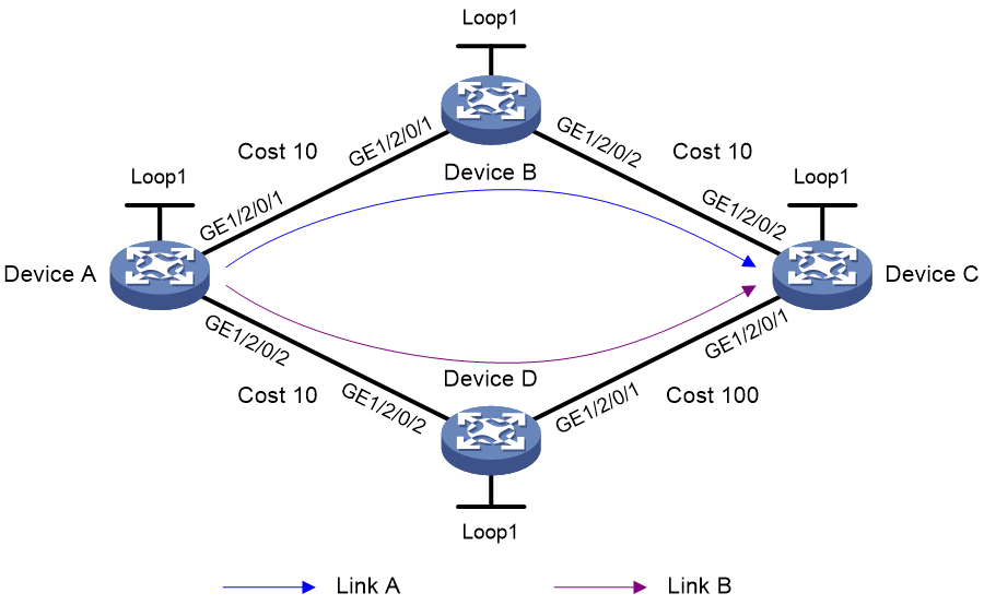
Table 1 Interface and IP address assignment
|
Device |
Interface |
IP address |
Device |
Interface |
IP address |
|
Device A |
Loop1 |
1::1/128 |
Device B |
Loop1 |
2::2/128 |
|
|
GE1/2/0/1 |
2000:1::1/64 |
|
GE1/2/0/1 |
2000:1::2/64 |
|
|
GE1/2/0/2 |
2000:4::1/64 |
|
GE1/2/0/2 |
2000:2::2/64 |
|
Device C |
Loop1 |
3::3/128 |
Device D |
Loop1 |
4::4/128 |
|
|
GE1/2/0/1 |
2000:3::3/64 |
|
GE1/2/0/1 |
2000:3::4/64 |
|
|
GE1/2/0/2 |
2000:2::3/64 |
|
GE1/2/0/2 |
2000:4::4/64 |
Procedure
1. Configure IPv6 addresses and prefixes for interfaces. (Details not shown.)
2. Configure Device A:
# Configure IPv6 IS-IS to achieve network level connectivity and set the IS-IS cost style to wide.
<DeviceA> system-view
[DeviceA] isis 1
[DeviceA-isis-1] network-entity 00.0000.0000.0001.00
[DeviceA-isis-1] cost-style wide
[DeviceA-isis-1] address-family ipv6
[DeviceA-isis-1-ipv6] quit
[DeviceA-isis-1] quit
[DeviceA] interface gigabitethernet 1/2/0/1
[DeviceA-GigabitEthernet1/2/0/1] isis ipv6 enable 1
[DeviceA-GigabitEthernet1/2/0/1] isis cost 10
[DeviceA-GigabitEthernet1/2/0/1] quit
[DeviceA] interface gigabitethernet 1/2/0/2
[DeviceA-GigabitEthernet1/2/0/2] isis ipv6 enable 1
[DeviceA-GigabitEthernet1/2/0/2] isis cost 10
[DeviceA-GigabitEthernet1/2/0/2] quit
[DeviceA] interface loopback 1
[DeviceA-LoopBack1] isis ipv6 enable 1
[DeviceA-LoopBack1] quit
# Enable SRv6 and configure a locator.
[DeviceA] segment-routing ipv6
[DeviceA-segment-routing-ipv6] locator aaa ipv6-prefix 11:: 64 static 32
[DeviceA-segment-routing-ipv6-locator-aaa] quit
[DeviceA-segment-routing-ipv6] quit
# Configure IPv6 IS-IS TI-LFA FRR.
[DeviceA] isis 1
[DeviceA-isis-1] address-family ipv6
[DeviceA-isis-1-ipv6] fast-reroute lfa
[DeviceA-isis-1-ipv6] fast-reroute ti-lfa
[DeviceA-isis-1-ipv6] quit
[DeviceA-isis-1] quit
# Apply the locator to the IPv6 IS-IS process.
[DeviceA] isis 1
[DeviceA-isis-1] address-family ipv6
[DeviceA-isis-1-ipv6] segment-routing ipv6 locator aaa
[DeviceA-isis-1-ipv6] quit
[DeviceA-isis-1] quit
3. Configure Device B:
# Configure IPv6 IS-IS to achieve network level connectivity and set the IS-IS cost style to wide.
<DeviceB> system-view
[DeviceB] isis 1
[DeviceB-isis-1] network-entity 00.0000.0000.0002.00
[DeviceB-isis-1] cost-style wide
[DeviceB-isis-1] address-family ipv6
[DeviceB-isis-1-ipv6] quit
[DeviceB-isis-1] quit
[DeviceB] interface gigabitethernet 1/2/0/1
[DeviceB-GigabitEthernet1/2/0/1] isis ipv6 enable 1
[DeviceB-GigabitEthernet1/2/0/1] isis cost 10
[DeviceB-GigabitEthernet1/2/0/1] quit
[DeviceB] interface gigabitethernet 1/2/0/2
[DeviceB-GigabitEthernet1/2/0/2] isis ipv6 enable 1
[DeviceB-GigabitEthernet1/2/0/2] isis cost 10
[DeviceB-GigabitEthernet1/2/0/2] quit
[DeviceB] interface loopback 1
[DeviceB-LoopBack1] isis ipv6 enable 1
[DeviceB-LoopBack1] quit
# Enable SRv6 and configure a locator.
[DeviceB] segment-routing ipv6
[DeviceB-segment-routing-ipv6] locator bbb ipv6-prefix 22:: 64 static 32
[DeviceB-segment-routing-ipv6-locator-bbb] quit
[DeviceB-segment-routing-ipv6] quit
# Apply the locator to the IPv6 IS-IS process.
[DeviceB] isis 1
[DeviceB-isis-1] address-family ipv6
[DeviceB-isis-1-ipv6] segment-routing ipv6 locator bbb
[DeviceB-isis-1-ipv6] quit
[DeviceB-isis-1] quit
4. Configure Device C:
# Configure IPv6 IS-IS to achieve network level connectivity and set the IS-IS cost style to wide.
<DeviceC> system-view
[DeviceC] isis 1
[DeviceC-isis-1] network-entity 00.0000.0000.0003.00
[DeviceC-isis-1] cost-style wide
[DeviceC-isis-1] address-family ipv6
[DeviceC-isis-1-ipv6] quit
[DeviceC-isis-1] quit
[DeviceC] interface gigabitethernet 1/2/0/1
[DeviceC-GigabitEthernet1/2/0/1] isis ipv6 enable 1
[DeviceC-GigabitEthernet1/2/0/1] isis cost 10
[DeviceC-GigabitEthernet1/2/0/1] quit
[DeviceC] interface gigabitethernet 1/2/0/2
[DeviceC-GigabitEthernet1/2/0/2] isis ipv6 enable 1
[DeviceC-GigabitEthernet1/2/0/2] isis cost 100
[DeviceC-GigabitEthernet1/2/0/2] quit
[DeviceC] interface loopback 1
[DeviceC-LoopBack1] isis ipv6 enable 1
[DeviceC-LoopBack1] quit
# Enable SRv6 and configure a locator.
[DeviceC] segment-routing ipv6
[DeviceC-segment-routing-ipv6] locator ccc ipv6-prefix 33:: 64 static 32
[DeviceC-segment-routing-ipv6-locator-ccc] quit
[DeviceC-segment-routing-ipv6] quit
# Apply the locator to the IPv6 IS-IS process.
[DeviceC] isis 1
[DeviceC-isis-1] address-family ipv6
[DeviceC-isis-1-ipv6] segment-routing ipv6 locator ccc
[DeviceC-isis-1-ipv6] quit
[DeviceC-isis-1] quit
5. Configure Device D:
# Configure IPv6 IS-IS to achieve network level connectivity and set the IS-IS cost style to wide.
<DeviceD> system-view
[DeviceD] isis 1
[DeviceD-isis-1] network-entity 00.0000.0000.0004.00
[DeviceD-isis-1] cost-style wide
[DeviceD-isis-1] address-family ipv6
[DeviceD-isis-1-ipv6] quit
[DeviceD-isis-1] quit
[DeviceD] interface gigabitethernet 1/2/0/1
[DeviceD-GigabitEthernet1/2/0/1] isis ipv6 enable 1
[DeviceD-GigabitEthernet1/2/0/1] isis cost 100
[DeviceD-GigabitEthernet1/2/0/1] quit
[DeviceD] interface gigabitethernet 1/2/0/2
[DeviceD-GigabitEthernet1/2/0/2] isis ipv6 enable 1
[DeviceD-GigabitEthernet1/2/0/2] isis cost 10
[DeviceD-GigabitEthernet1/2/0/2] quit
[DeviceD] interface loopback 1
[DeviceD-LoopBack1] isis ipv6 enable 1
[DeviceD-LoopBack1] quit
# Enable SRv6 and configure a locator.
[DeviceD] segment-routing ipv6
[DeviceD-segment-routing-ipv6] locator ddd ipv6-prefix 44:: 64 static 32
[DeviceD-segment-routing-ipv6-locator-ddd] quit
[DeviceD-segment-routing-ipv6] quit
# Apply the locator to the IPv6 IS-IS process.
[DeviceD] isis 1
[DeviceD-isis-1] address-family ipv6
[DeviceD-isis-1-ipv6] segment-routing ipv6 locator ddd
[DeviceD-isis-1-ipv6] quit
[DeviceD-isis-1] quit
Verifying the configuration
# Display IPv6 IS-IS routing information for 3::3/128.
[DeviceA] display isis route ipv6 3::3 128 verbose
Route information for IS-IS(1)
------------------------------
Level-1 IPv6 forwarding table
-----------------------------
IPv6 dest : 3::3/128
Flag : R/L/- Cost : 10
Admin tag : - Src count : 2
Nexthop : FE80::4449:7CFF:FEE0:206
Interface : GE1/2/0/1
TI-LFA:
Interface : GE1/2/0/2
BkNextHop : FE80::4449:91FF:FE42:407
LsIndex : 0x80000001
Backup label stack(top->bottom): {44::1:0:1}
Nib ID : 0x24000006
Flags: D-Direct, R-Added to Rib, L-Advertised in LSPs, U-Up/Down Bit Set
The output shows TI-LFA backup next hop information.
Example: Configuring MPLS L3VPN over SRv6
Network configuration
As shown in Figure 13, the backbone network is an IPv6 network, and VPN 1 is an IPv4 network. Deploy MPLS L3VPN over SRv6 between PE 1 and PE 2 and use an SRv6 tunnel to transmit VPNv4 traffic between the PEs.
· Configure EBGP to exchange VPN routing information between the CEs and PEs.
· Configure IPv6 IS-IS on the PEs in the same AS to realize IPv6 network connectivity.
· Configure MP-IBGP to exchange VPNv4 routing information between the PEs.
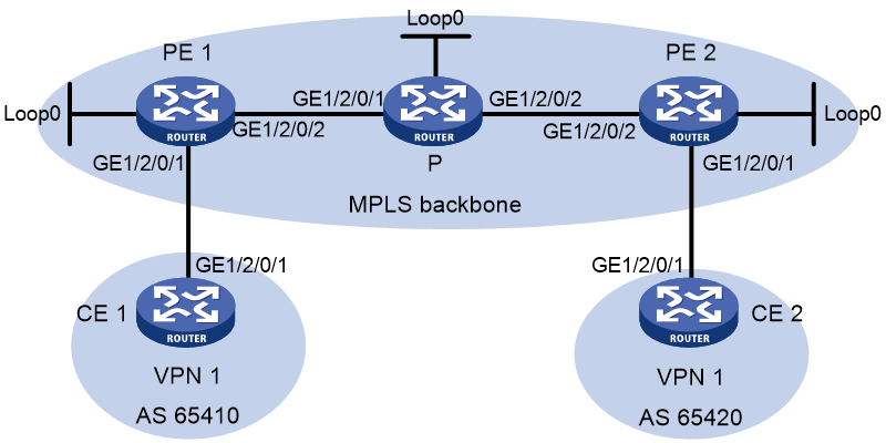
Table 2 Interface and IP address assignment
|
Device |
Interface |
IP address |
Device |
Interface |
IP address |
|
CE 1 |
GE1/2/0/1 |
10.1.1.2/24 |
PE 2 |
Loop0 |
3::3/128 |
|
PE 1 |
Loop0 |
1::1/128 |
|
GE1/2/0/1 |
10.2.1.1/24 |
|
|
GE1/2/0/1 |
10.1.1.1/24 |
|
GE1/2/0/2 |
2002::1/96 |
|
|
GE1/2/0/2 |
2001::1/96 |
CE 2 |
GE1/2/0/1 |
10.2.1.2/24 |
|
P |
Loop0 |
2::2/128 |
|
|
|
|
|
GE1/2/0/1 |
2001::2/96 |
|
|
|
|
|
GE1/2/0/2 |
2002::2/96 |
|
|
|
Procedure
1. Configure IPv6 IS-IS on the PEs and device P for network connectivity between the devices:
# Configure PE 1.
<PE1> system-view
[PE1] isis 1
[PE1-isis-1] is-level level-1
[PE1-isis-1] cost-style wide
[PE1-isis-1] network-entity 10.1111.1111.1111.00
[PE1-isis-1] address-family ipv6 unicast
[PE1-isis-1-ipv6] quit
[PE1-isis-1] quit
[PE1] interface loopback 0
[PE1-LoopBack0] ipv6 address 1::1 128
[PE1-LoopBack0] isis ipv6 enable 1
[PE1-LoopBack0] quit
[PE1] interface gigabitethernet 1/2/0/2
[PE1-GigabitEthernet1/2/0/2] ipv6 address 2001::1 96
[PE1-GigabitEthernet1/2/0/2] isis ipv6 enable
[PE1-GigabitEthernet1/2/0/2] quit
# Configure P.
<P> system-view
[P] isis
[P-isis-1] is-level level-1
[P-isis-1] cost-style wide
[P-isis-1] network-entity 10.2222.2222.2222.00
[P-isis-1] address-family ipv6 unicast
[P-isis-1-ipv6] quit
[P-isis-1] quit
[P] interface loopback 0
[P-LoopBack0] ipv6 address 2::2 128
[P-LoopBack0] isis ipv6 enable
[P-LoopBack0] quit
[P] interface gigabitethernet 1/2/0/1
[P-GigabitEthernet1/2/0/1] ipv6 address 2001::2 96
[P-GigabitEthernet1/2/0/1] isis ipv6 enable
[P-GigabitEthernet1/2/0/1] quit
[P] interface gigabitethernet 1/2/0/2
[P-GigabitEthernet1/2/0/2] ipv6 address 2002::2 96
[P-GigabitEthernet1/2/0/2] isis ipv6 enable
[P-GigabitEthernet1/2/0/2] quit
# Configure PE 2.
<PE2> system-view
[PE2] isis
[PE2-isis-1] is-level level-1
[PE2-isis-1] cost-style wide
[PE2-isis-1] network-entity 10.3333.3333.3333.00
[PE2-isis-1] address-family ipv6 unicast
[PE2-isis-1-ipv6] quit
[PE2-isis-1] quit
[PE2] interface loopback 0
[PE2-LoopBack0] ipv6 address 3::3 128
[PE2-LoopBack0] isis ipv6 enable
[PE2-LoopBack0] quit
[PE2] interface gigabitethernet 1/2/0/2
[PE2-GigabitEthernet1/2/0/2] ipv6 address 2002::1 96
[PE2-GigabitEthernet1/2/0/2] isis ipv6 enable
[PE2-GigabitEthernet1/2/0/2] quit
# Verify that PE 1, P, and PE 2 have established IPv6 IS-IS neighbor relationships and the neighbor state is up.
[PE1] display isis peer
[P] display isis peer
[PE2] display isis peer
# Verify that PE 1 and PE 2 each learn a route destined for the loopback interface of each other.
[PE1] display isis route ipv6
[PE2] display isis route ipv6
2. Configure VPN instance settings on PE 1 and PE 2 and verify that each CE can access its local PE:
# Configure PE 1.
[PE1] ip vpn-instance vpn1
[PE1-vpn-instance-vpn1] route-distinguisher 100:1
[PE1-vpn-instance-vpn1] vpn-target 111:1
[PE1-vpn-instance-vpn1] quit
[PE1] interface gigabitethernet 1/2/0/1
[PE1-GigabitEthernet1/2/0/1] ip binding vpn-instance vpn1
[PE1-GigabitEthernet1/2/0/1] ip address 10.1.1.1 24
[PE1-GigabitEthernet1/2/0/1] quit
# Configure PE 2.
[PE2] ip vpn-instance vpn1
[PE2-vpn-instance-vpn1] route-distinguisher 100:1
[PE2-vpn-instance-vpn1] vpn-target 111:1
[PE2-vpn-instance-vpn1] quit
[PE2] interface gigabitethernet 1/2/0/1
[PE2-GigabitEthernet1/2/0/1] ip binding vpn-instance vpn1
[PE2-GigabitEthernet1/2/0/1] ip address 10.2.1.1 24
[PE2-GigabitEthernet1/2/0/1] quit
# Configure IP addresses for the interfaces on the CEs, as shown in Figure 13. (Details not shown.)
# Display VPN instance settings on each PE. This step uses PE 1 as an example.
[PE1] display ip vpn-instance
Total VPN-Instances configured : 1
Total IPv4 VPN-Instances configured : 1
Total IPv6 VPN-Instances configured : 1
VPN-Instance Name RD Address family Create time
vpn1 100:1 IPv4/IPv6 2019/08/12 13:59:39
# Verify that each PE can ping its local CE. This step uses PE 1 and CE 1 as an example.
[PE1] ping -vpn-instance vpn1 10.1.1.2
Ping 10.1.1.2 (10.1.1.2): 56 data bytes, press CTRL+C to break
56 bytes from 10.1.1.2: icmp_seq=0 ttl=255 time=2.000 ms
56 bytes from 10.1.1.2: icmp_seq=1 ttl=255 time=0.000 ms
56 bytes from 10.1.1.2: icmp_seq=2 ttl=255 time=1.000 ms
56 bytes from 10.1.1.2: icmp_seq=3 ttl=255 time=0.000 ms
56 bytes from 10.1.1.2: icmp_seq=4 ttl=255 time=0.000 ms
--- Ping statistics for 10.1.1.2 in VPN instance vpn1 ---
5 packet(s) transmitted, 5 packet(s) received, 0.0% packet loss
round-trip min/avg/max/std-dev = 0.000/0.600/2.000/0.800 ms
3. Set up an EBGP peer relationship between each PE and its local CE and distribute VPN routes to EBGP:
# Configure CE 1.
<CE1> system-view
[CE1] bgp 65410
[CE1-bgp-default] peer 10.1.1.1 as-number 100
[CE1-bgp-default] address-family ipv4 unicast
[CE1-bgp-default-ipv4] peer 10.1.1.1 enable
[CE1-bgp-default-ipv4] import-route direct
[CE1-bgp-default-ipv4] quit
[CE1-bgp-default] quit
# Configure CE 2 in the same way as CE 1 is configured. (Details not shown.)
# Configure PE 1.
[PE1] bgp 100
[PE1-bgp-default] router-id 1.1.1.1
[PE1-bgp-default] ip vpn-instance vpn1
[PE1-bgp-default-vpn1] peer 10.1.1.2 as-number 65410
[PE1-bgp-default-vpn1] address-family ipv4 unicast
[PE1-bgp-default-ipv4-vpn1] peer 10.1.1.2 enable
[PE1-bgp-default-ipv4-vpn1] quit
[PE1-bgp-default-vpn1] quit
# Configure PE 2 in the same way PE 1 is configured. (Details not shown.)
# Verify that the PEs have established BGP peer relationships with their local CEs and the peers are in established state.
[PE1] display bgp peer ipv4 vpn-instance
[PE2] display bgp peer ipv4 vpn-instance
4. Set up an MP-IBGP peer relationship between PE 1 and PE 2:
# Configure PE 1.
[PE1] bgp 100
[PE1-bgp-default] peer 3::3 as-number 100
[PE1-bgp-default] peer 3::3 connect-interface loopback 0
[PE1-bgp-default] address-family vpnv4
[PE1-bgp-default-vpnv4] peer 3::3 enable
[PE1-bgp-default-vpnv4] quit
[PE1-bgp-default] quit
# Configure PE 2.
[PE2] bgp 100
[PE2-bgp-default] peer 1::1 as-number 100
[PE2-bgp-default] peer 1::1 connect-interface loopback 0
[PE2-bgp-default] address-family vpnv4
[PE2-bgp-default-vpnv4] peer 1::1 enable
[PE2-bgp-default-vpnv4] quit
[PE2-bgp-default] quit
# Verify that the PEs have established a BGP peer relationship and the peers are in established state.
[PE1] display bgp peer vpnv4
[PE2] display bgp peer vpnv4
5. Specify a source address for the outer IPv6 header of SRv6-encapsulated MPLS L3VPN packets on PE 1 and PE 2:
# Configure PE 1.
[PE1] segment-routing ipv6
[PE1-segment-routing-ipv6] encapsulation source-address 11::11
# Configure PE 2.
[PE2] segment-routing ipv6
[PE2-segment-routing-ipv6] encapsulation source-address 33::33
6. Configure the destination address (End.DT4 SID) of the outer IPv6 header for SRv6-encapsulated MPLS L3VPN packets:
# Configure PE 1.
[PE1-segment-routing-ipv6] locator aaa ipv6-prefix 1:2::1:0 120 static 8
[PE1-segment-routing-ipv6-locator-aaa] opcode 1 end-dt4 vpn-instance vpn1
[PE1-segment-routing-ipv6-locator-aaa] quit
[PE1-segment-routing-ipv6] quit
# Configure PE 2.
[PE2-segment-routing-ipv6] locator bbb ipv6-prefix 6:5::1:0 120 static 8
[PE2-segment-routing-ipv6-locator-bbb] opcode 1 end-dt4 vpn-instance vpn1
[PE2-segment-routing-ipv6-locator-bbb] quit
[PE2-segment-routing-ipv6] quit
# Verify that the PEs have distributed the End.DT4 SIDs to the routing table and generated SRv6 routes. This step uses PE 1 as an example.
[PE1] display ipv6 routing-table protocol srv6
Summary count : 1
SRv6 Routing table status : <Active>
Summary count : 1
Destination: 1:2::1:1/128 Protocol : SRv6
NextHop : ::1 Preference: 4
Interface : InLoop0 Cost : 0
SRv6 Routing table status : <Inactive>
Summary count : 0
7. Add End.DT4 SIDs to private network routes on PE 1 and PE 2:
# Configure PE 1.
[PE1] bgp 100
[PE1-bgp-default] ip vpn-instance vpn1
[PE1-bgp-default-vpn1] address-family ipv4 unicast
[PE1-bgp-default-ipv4-vpn1] segment-routing ipv6 locator aaa
[PE1-bgp-default-ipv4-vpn1] quit
[PE1-bgp-default-vpn1] quit
[PE1-bgp-default] quit
[PE1] interface loopback 1
[PE1-LoopBack1] ipv6 address 1:2::1 64
[PE1-LoopBack1] isis ipv6 enable
[PE1-LoopBack1] quit
# Configure PE 2.
[PE2] bgp 100
[PE2-bgp-default] ip vpn-instance vpn1
[PE2-bgp-default-vpn1] address-family ipv4 unicast
[PE2-bgp-default-ipv4-vpn1] segment-routing ipv6 locator bbb
[PE2-bgp-default-ipv4-vpn1] quit
[PE2-bgp-default-vpn1] quit
[PE2-bgp-default] quit
[PE2] interface loopback 1
[PE2-LoopBack1] ipv6 address 6:5::1 64
[PE2-LoopBack1] isis ipv6 enable
[PE2-LoopBack1] quit
8. Enable IPv6 peers on the PEs to exchange End.DT4 SIDs and enable the SID-route-recursion feature:
# Configure PE 1.
[PE1] bgp 100
[PE1-bgp-default] address-family vpnv4
[PE1-bgp-default-vpnv4] peer 3::3 prefix-sid
[PE1-bgp-default-vpnv4] quit
[PE1-bgp-default] ip vpn-instance vpn1
[PE1-bgp-default-vpn1] address-family ipv4 unicast
[PE1-bgp-default-ipv4-vpn1] segment-routing ipv6 best-effort
[PE1-bgp-default-ipv4-vpn1] quit
[PE1-bgp-default-vpn1] quit
[PE1-bgp-default] quit
# Configure PE 2.
[PE2] bgp 100
[PE2-bgp-default] address-family vpnv4
[PE2-bgp-default-vpnv4] peer 1::1 prefix-sid
[PE2-bgp-default-vpnv4] quit
[PE2-bgp-default] ip vpn-instance vpn1
[PE2-bgp-default-vpn1] address-family ipv4 unicast
[PE2-bgp-default-ipv4-vpn1] segment-routing ipv6 best-effort
[PE2-bgp-default-ipv4-vpn1] quit
[PE2-bgp-default-vpn1] quit
[PE2-bgp-default] quit
# Display BGP VPNv4 routing information on each PE and verify that the routes advertised by the PEs have the SID attribute. This step uses PE 1 as an example.
[PE1] display bgp routing-table vpnv4 10.2.1.0
BGP local router ID: 1.1.1.1
Local AS number: 100
Route distinguisher: 100:1(vpn1)
Total number of routes: 1
Paths: 1 available, 1 best
BGP routing table information of 10.2.1.0/24:
From : 3::3 (3.3.3.3)
Rely nexthop : FE80::2A96:34FF:FE9D:216
Original nexthop: 3::3
Out interface : GigabitEthernet1/2/0/2
Route age : 00h14m23s
OutLabel : 3
Ext-Community : <RT: 111:1>
RxPathID : 0x0
TxPathID : 0x0
PrefixSID : End.DT4 SID <6:5::1:1>
AS-path : 65420
Origin : incomplete
Attribute value : MED 0, localpref 100, pref-val 0
State : valid, internal, best
IP precedence : N/A
QoS local ID : N/A
Traffic index : N/A
Tunnel policy : NULL
Rely tunnel IDs : N/A
Verifying the configuration
# Display IPv4 routing table information on the PEs and verify that each PE has a route destined for the remote CE and the next hop of the route is the End.DT4 SID of the route. This step uses PE 1 as an example.
[PE1] display ip routing-table vpn-instance vpn1
Destinations : 11 Routes : 11
Destination/Mask Proto Pre Cost NextHop Interface
0.0.0.0/32 Direct 0 0 127.0.0.1 InLoop0
10.1.1.0/24 Direct 0 0 10.1.1.1 GE1/2/0/1
10.1.1.0/32 Direct 0 0 10.1.1.1 GE1/2/0/1
10.1.1.1/32 Direct 0 0 127.0.0.1 InLoop0
10.1.1.255/32 Direct 0 0 10.1.1.1 GE1/2/0/1
10.2.1.0/24 BGP 255 0 6:5::1:1 GE1/2/0/2
127.0.0.0/8 Direct 0 0 127.0.0.1 InLoop0
127.0.0.0/32 Direct 0 0 127.0.0.1 InLoop0
127.0.0.1/32 Direct 0 0 127.0.0.1 InLoop0
127.255.255.255/32 Direct 0 0 127.0.0.1 InLoop0
255.255.255.255/32 Direct 0 0 127.0.0.1 InLoop0
# Verify that CE 1 and CE 2 can ping each other. (Details not shown.)
