- Table of Contents
-
- H3C Fixed Port Campus Switches Configuration Examples-B70D029-6W100
- 01-Login Management Configuration Examples
- 02-RBAC Configuration Examples
- 03-Software Upgrade Examples
- 04-ISSU Configuration Examples
- 05-Software Patching Examples
- 06-Ethernet Link Aggregation Configuration Examples
- 07-Port Isolation Configuration Examples
- 08-Spanning Tree Configuration Examples
- 09-VLAN Configuration Examples
- 10-VLAN Tagging Configuration Examples
- 11-DHCP Snooping Configuration Examples
- 12-Cross-Subnet Dynamic IP Address Allocation Configuration Examples
- 13-IPv6 over IPv4 Tunneling with OSPFv3 Configuration Examples
- 14-IPv6 over IPv4 GRE Tunnel Configuration Examples
- 15-GRE with OSPF Configuration Examples
- 16-OSPF Configuration Examples
- 17-IS-IS Configuration Examples
- 18-BGP Configuration Examples
- 19-Policy-Based Routing Configuration Examples
- 20-OSPFv3 Configuration Examples
- 21-IPv6 IS-IS Configuration Examples
- 22-Routing Policy Configuration Examples
- 23-IGMP Snooping Configuration Examples
- 24-IGMP Configuration Examples
- 25-MLD Snooping Configuration Examples
- 26-IPv6 Multicast VLAN Configuration Examples
- 27-ACL Configuration Examples
- 28-Traffic Policing Configuration Examples
- 29-GTS and Rate Limiting Configuration Examples
- 30-Priority Mapping and Queue Scheduling Configuration Examples
- 31-Traffic Filtering Configuration Examples
- 32-AAA Configuration Examples
- 33-Port Security Configuration Examples
- 34-Portal Configuration Examples
- 35-SSH Configuration Examples
- 36-IP Source Guard Configuration Examples
- 37-Ethernet OAM Configuration Examples
- 38-CFD Configuration Examples
- 39-DLDP Configuration Examples
- 40-VRRP Configuration Examples
- 41-BFD Configuration Examples
- 42-NTP Configuration Examples
- 43-SNMP Configuration Examples
- 44-NQA Configuration Examples
- 45-Mirroring Configuration Examples
- 46-sFlow Configuration Examples
- 47-OpenFlow Configuration Examples
- 48-MAC Address Table Configuration Examples
- 49-Static Multicast MAC Address Entry Configuration Examples
- 50-IP Unnumbered Configuration Examples
- 51-MVRP Configuration Examples
- 52-MCE Configuration Examples
- 53-Attack Protection Configuration Examples
- 54-Smart Link Configuration Examples
- 55-RRPP Configuration Examples
- 56-BGP Route Selection Configuration Examples
- 57-IS-IS Route Summarization Configuration Examples
- 58-IRF Configuration Examples
- 59-VXLAN Configuration Examples
- Related Documents
-
| Title | Size | Download |
|---|---|---|
| 16-OSPF Configuration Examples | 72.04 KB |
Example: Configuring OSPF route filtering
Applicable hardware and software versions
Configuring route redistribution
Configuring OSPF route filtering
Introduction
This document provides OSPF route filtering configuration examples.
Prerequisites
This document is not restricted to specific software or hardware versions.
The configuration examples in this document were created and verified in a lab environment, and all the devices were started with the factory default configuration. When you are working on a live network, make sure you understand the potential impact of every command on your network.
This document assumes that you have basic knowledge of OSPF route filtering.
Example: Configuring OSPF route filtering
Network configuration
As shown in Figure 1, the devices of an enterprise reside in OSPF and RIP domains.
Configure route redistribution between OSPF and RIP to interconnect the devices.
Configure route filtering on Device E, Device C, and Device D to meet the following requirements:
· The route destined for R&D department 2 is not redistributed to OSPF.
· Marketing department 1 cannot reach R&D department 1.
· R&D department 1 and the After-sale service department cannot reach Marketing department 2.
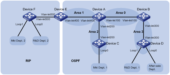
Table 1 Interface and IP address assignment
|
Device |
Interface |
IP address |
Device |
Interface |
IP address |
|
Device A |
Vlan-int100 |
10.1.1.1/24 |
Device B |
Vlan-int100 |
10.1.1.2/24 |
|
|
Vlan-int200 |
10.2.1.1/24 |
|
Vlan-int300 |
10.3.1.1/24 |
|
|
Vlan-int400 |
10.4.1.1/24 |
|
|
|
|
Device C |
Vlan-int200 |
10.2.1.2/24 |
Device D |
Vlan-int300 |
10.3.1.2/24 |
|
|
Loop0 |
192.168.3.1/24 |
|
Loop0 |
192.168.1.1/24 |
|
|
|
|
|
Loop1 |
192.168.2.1/24 |
|
Device E |
Vlan-int400 |
10.4.1.2/24 |
Device F |
Vlan-int500 |
10.5.1.2/24 |
|
|
Vlan-int500 |
10.5.1.1/24 |
|
Loop0 |
192.168.4.1/24 |
|
|
|
|
|
Loop1 |
192.168.5.1/24 |
Applicable hardware and software versions
The following matrix shows the hardware and software versions to which this configuration example is applicable:
|
Hardware |
Software version |
|
S6520X-HI switch series S6520X-EI switch series |
Supported in Release 1110P01 |
|
S6520X-SI switch series S6520-SI switch series S5000-EI switch series MS4600 switch series |
Supported in Release 1110P01 |
Restrictions and guidelines
When you configure OSPF route filtering, follow these restrictions and guidelines:
· The filter-policy export command that filters redistributed routes takes effect only on an ASBR.
· OSPF filters routes calculated using received LSAs. It does not filter LSAs.
· IP communication is bidirectional. If a router filters out a route destined for Network A, the subnets attached to the router cannot reach Network A, and Network A cannot reach the subnets.
· When you configure route filtering by referencing an ACL, configure the rule permit source any item following multiple rule deny source items to allow unmatched routes to pass.
Procedures
Configuring IP addresses
# Configure an IP address for VLAN-interface 100.
<DeviceA> system-view
[DeviceA] interface vlan-interface 100
[DeviceA-Vlan-interface100] ip address 10.1.1.1 24
# Configure IP addresses for other interfaces in the same way VLAN-interface 100 is configured. (Details not shown.)
Configuring OSPF
# Enable OSPF on Device A.
<DeviceA> system-view
[DeviceA] ospf
[DeviceA-ospf-1] area 0
[DeviceA-ospf-1-area-0.0.0.0] network 10.1.1.0 0.0.0.255
[DeviceA-ospf-1-area-0.0.0.0] quit
[DeviceA-ospf-1] area 2
[DeviceA-ospf-1-area-0.0.0.2] network 10.2.1.0 0.0.0.255
[DeviceA-ospf-1-area-0.0.0.2] quit
[DeviceA-ospf-1] area 1
[DeviceA-ospf-1-area-0.0.0.1] network 10.4.1.0 0.0.0.255
[DeviceA-ospf-1-area-0.0.0.1] quit
[DeviceA-ospf-1] quit
# Enable OSPF on Device B.
<DeviceB> system-view
[DeviceB] ospf
[DeviceB-ospf-1] area 0
[DeviceB-ospf-1-area-0.0.0.0] network 10.1.1.0 0.0.0.255
[DeviceB-ospf-1-area-0.0.0.0] quit
[DeviceB-ospf-1] area 3
[DeviceB-ospf-1-area-0.0.0.3] network 10.3.1.0 0.0.0.255
[DeviceB-ospf-1-area-0.0.0.3] quit
[DeviceB-ospf-1] quit
# Enable OSPF on Device C.
<DeviceC> system-view
[DeviceC] ospf
[DeviceC-ospf-1] area 2
[DeviceC-ospf-1-area-0.0.0.2] network 10.2.1.0 0.0.0.255
[DeviceC-ospf-1-area-0.0.0.2] network 192.168.3.0 0.0.0.255
[DeviceC-ospf-1-area-0.0.0.2] quit
[DeviceC-ospf-1] quit
# Enable OSPF on Device D.
<DeviceD> system-view
[DeviceD] ospf
[DeviceD-ospf-1] area 3
[DeviceD-ospf-1-area-0.0.0.3] network 10.3.1.0 0.0.0.255
[DeviceD-ospf-1-area-0.0.0.3] network 192.168.1.0 0.0.0.255
[DeviceD-ospf-1-area-0.0.0.3] network 192.168.2.0 0.0.0.255
[DeviceD-ospf-1-area-0.0.0.3] quit
[DeviceD-ospf-1] quit
# Enable OSPF on Device E.
<DeviceE> system-view
[DeviceE] ospf
[DeviceE-ospf-1] area 1
[DeviceE-ospf-1-area-0.0.0.1] network 10.4.1.0 0.0.0.255
[DeviceE-ospf-1-area-0.0.0.1] quit
[DeviceE-ospf-1] quit
Configuring RIP
# Enable RIP on Device E.
<DeviceE> system-view
[DeviceE] rip
[DeviceE-rip-1] version 2
[DeviceE-rip-1] undo summary
[DeviceE-rip-1] network 10.5.1.0 0.0.0.255
[DeviceE-rip-1] quit
# Enable RIP on Device F.
[DeviceF] rip
[DeviceF-rip-1] version 2
[DeviceF-rip-1] undo summary
[DeviceF-rip-1] network 10.5.1.0 0.0.0.255
[DeviceF-rip-1] network 192.168.4.0 0.0.0.255
[DeviceF-rip-1] network 192.168.4.0 0.0.0.255
[DeviceF-rip-1] quit
Configuring route redistribution
# Configure Device E to redistribute OSPF and direct routes to RIP.
<DeviceE> system-view
[DeviceE] rip
[DeviceE-rip-1] import-route direct
[DeviceE-rip-1] import-route ospf
[DeviceE-rip-1] quit
# Configure Device E to redistribute RIP and direct routes to OSPF.
[DeviceE] ospf
[DeviceE-ospf-1] import-route direct
[DeviceE-ospf-1] import-route rip
[DeviceE-ospf-1] quit
# Verify that Device E has routes to all networks.
[DeviceE] display ip routing-table
Destinations : 24 Routes : 24
Destination/Mask Proto Pre Cost NextHop Interface
0.0.0.0/32 Direct 0 0 127.0.0.1 InLoop0
10.1.1.0/24 O_INTER 10 2 10.4.1.1 Vlan400
10.2.1.0/24 O_INTER 10 2 10.4.1.1 Vlan400
10.3.1.0/24 O_INTER 10 3 10.4.1.1 Vlan400
10.4.1.0/24 Direct 0 0 10.4.1.2 Vlan400
10.4.1.0/32 Direct 0 0 10.4.1.2 Vlan400
10.4.1.2/32 Direct 0 0 127.0.0.1 InLoop0
10.4.1.255/32 Direct 0 0 10.4.1.2 Vlan400
10.5.1.0/24 Direct 0 0 10.5.1.1 Vlan500
10.5.1.0/32 Direct 0 0 10.5.1.1 Vlan500
10.5.1.1/32 Direct 0 0 127.0.0.1 InLoop0
10.5.1.255/32 Direct 0 0 10.5.1.1 Vlan500
127.0.0.0/8 Direct 0 0 127.0.0.1 InLoop0
127.0.0.0/32 Direct 0 0 127.0.0.1 InLoop0
127.0.0.1/32 Direct 0 0 127.0.0.1 InLoop0
127.255.255.255/32 Direct 0 0 127.0.0.1 InLoop0
192.168.1.1/32 O_INTER 10 3 10.4.1.1 Vlan400
192.168.2.1/32 O_INTER 10 3 10.4.1.1 Vlan400
192.168.3.1/32 O_INTER 10 2 10.4.1.1 Vlan400
192.168.4.0/24 RIP 100 1 10.5.1.2 Vlan500
192.168.5.0/24 RIP 100 1 10.5.1.2 Vlan500
224.0.0.0/4 Direct 0 0 0.0.0.0 NULL0
224.0.0.0/24 Direct 0 0 0.0.0.0 NULL0
255.255.255.255/32 Direct 0 0 127.0.0.1 InLoop0
# Verify that other devices have routes to all networks. (Details not shown.)
Configuring OSPF route filtering
# On Device C, configure IPv4 basic ACL 2000 to permit any subnet except 192.168.2.0/24.
<DeviceC> system-view
[DeviceC] acl basic 2000
[DeviceC-acl-ipv4-basic-2000] rule 0 deny source 192.168.2.0 0.0.0.255
[DeviceC-acl-ipv4-basic-2000] rule permit source any
[DeviceC-acl-ipv4-basic-2000] quit
# On Device C, use ACL 2000 to filter received routes.
[DeviceC] ospf
[DeviceC-ospf-1] filter-policy 2000 import
[DeviceC-ospf-1] quit
# On Device D, configure IPv4 basic ACL 2000 to permit any subnet except 192.168.5.0/24.
<DeviceD> system-view
[DeviceD] acl basic 2000
[DeviceD-acl-ipv4-basic-2000] rule 0 deny source 192.168.5.0 0.0.0.255
[DeviceD-acl-ipv4-basic-2000] rule permit source any
[DeviceD-acl-ipv4-basic-2000] quit
# On Device D, use ACL 2000 to filter received routes.
[DeviceD] ospf
[DeviceD-ospf-1] filter-policy 2000 import
[DeviceD-ospf-1] quit
# On Device E, configure IPv4 basic ACL 2000 to permit any subnet except 192.168.4.0/24.
<DeviceE> system-view
[DeviceE] acl basic 2000
[DeviceE-acl-ipv4-basic-2000] rule 0 deny source 192.168.4.0 0.0.0.255
[DeviceE-acl-ipv4-basic-2000] rule permit source any
[DeviceE-acl-ipv4-basic-2000] quit
# On Device E, use ACL 2000 to filter routes redistributed from RIP.
[DeviceE] ospf
[DeviceE-ospf-1] filter-policy 2000 export rip 1
[DeviceE-ospf-1] quit
Verifying the configuration
# Verify that Device C does not have a route to 192.168.2.0/24.
[DeviceC] display ip routing-table
Destinations : 22 Routes : 22
Destination/Mask Proto Pre Cost NextHop Interface
0.0.0.0/32 Direct 0 0 127.0.0.1 InLoop0
10.1.1.0/24 O_INTER 10 2 10.2.1.1 Vlan200
10.2.1.0/24 Direct 0 0 10.2.1.2 Vlan200
10.2.1.0/32 Direct 0 0 10.2.1.2 Vlan200
10.2.1.2/32 Direct 0 0 127.0.0.1 InLoop0
10.2.1.255/32 Direct 0 0 10.2.1.2 Vlan200
10.3.1.0/24 O_INTER 10 3 10.2.1.1 Vlan200
10.4.1.0/24 O_INTER 10 2 10.2.1.1 Vlan200
10.5.1.0/24 O_ASE2 150 1 10.2.1.1 Vlan200
127.0.0.0/8 Direct 0 0 127.0.0.1 InLoop0
127.0.0.0/32 Direct 0 0 127.0.0.1 InLoop0
127.0.0.1/32 Direct 0 0 127.0.0.1 InLoop0
127.255.255.255/32 Direct 0 0 127.0.0.1 InLoop0
192.168.1.1/32 O_INTER 10 3 10.2.1.1 Vlan200
192.168.3.0/24 Direct 0 0 192.168.3.1 Loop0
192.168.3.0/32 Direct 0 0 192.168.3.1 Loop0
192.168.3.1/32 Direct 0 0 127.0.0.1 InLoop0
192.168.3.255/32 Direct 0 0 192.168.3.1 Loop0
192.168.5.0/24 O_ASE2 150 1 10.2.1.1 Vlan200
224.0.0.0/4 Direct 0 0 0.0.0.0 NULL0
224.0.0.0/24 Direct 0 0 0.0.0.0 NULL0
255.255.255.255/32 Direct 0 0 127.0.0.1 InLoop0
# Verify that Marketing department 1 cannot reach R&D department 1.
[DeviceC] ping -a 192.168.3.1 192.168.2.1
Ping 192.168.2.1 (192.168.2.1) from 192.168.3.1: 56 data bytes, press CTRL_C to
break
Request time out
Request time out
Request time out
Request time out
Request time out
--- Ping statistics for 192.168.2.1 ---
5 packet(s) transmitted, 0 packet(s) received, 100.0% packet loss
# Verify that Device D does not have a route to 192.168.5.0/24.
[DeviceD] display ip routing-table
Destinations : 25 Routes : 25
Destination/Mask Proto Pre Cost NextHop Interface
0.0.0.0/32 Direct 0 0 127.0.0.1 InLoop0
10.1.1.0/24 O_INTER 10 2 10.3.1.1 Vlan300
10.2.1.0/24 O_INTER 10 3 10.3.1.1 Vlan300
10.3.1.0/24 Direct 0 0 10.3.1.2 Vlan300
10.3.1.0/32 Direct 0 0 10.3.1.2 Vlan300
10.3.1.2/32 Direct 0 0 127.0.0.1 InLoop0
10.3.1.255/32 Direct 0 0 10.3.1.2 Vlan300
10.4.1.0/24 O_INTER 10 3 10.3.1.1 Vlan300
10.5.1.0/24 O_ASE2 150 1 10.3.1.1 Vlan300
127.0.0.0/8 Direct 0 0 127.0.0.1 InLoop0
127.0.0.0/32 Direct 0 0 127.0.0.1 InLoop0
127.0.0.1/32 Direct 0 0 127.0.0.1 InLoop0
127.255.255.255/32 Direct 0 0 127.0.0.1 InLoop0
192.168.1.0/24 Direct 0 0 192.168.1.1 Loop0
192.168.1.0/32 Direct 0 0 192.168.1.1 Loop0
192.168.1.1/32 Direct 0 0 127.0.0.1 InLoop0
192.168.1.255/32 Direct 0 0 192.168.1.1 Loop0
192.168.2.0/24 Direct 0 0 192.168.2.1 Loop1
192.168.2.0/32 Direct 0 0 192.168.2.1 Loop1
192.168.2.1/32 Direct 0 0 127.0.0.1 InLoop0
192.168.2.255/32 Direct 0 0 192.168.2.1 Loop1
192.168.3.1/32 O_INTER 10 3 10.3.1.1 Vlan300
224.0.0.0/4 Direct 0 0 0.0.0.0 NULL0
224.0.0.0/24 Direct 0 0 0.0.0.0 NULL0
255.255.255.255/32 Direct 0 0 127.0.0.1 InLoop0
# Verify that the After-sale service department cannot reach Marketing department 2.
[DeviceD] ping -a 192.168.1.1 192.168.5.1
Ping 192.168.5.1 (192.168.5.1) from 192.168.1.1: 56 data bytes, press CTRL_C to
break
Request time out
Request time out
Request time out
Request time out
Request time out
--- Ping statistics for 192.168.5.1 ---
5 packet(s) transmitted, 0 packet(s) received, 100.0% packet loss
# Verify that R&D department 1 cannot reach Marketing department 2.
[DeviceD] ping -a 192.168.2.1 192.168.5.1
Ping 192.168.5.1 (192.168.5.1) from 192.168.2.1: 56 data bytes, press CTRL_C to
break
Request time out
Request time out
Request time out
Request time out
Request time out
--- Ping statistics for 192.168.5.1 ---
5 packet(s) transmitted, 0 packet(s) received, 100.0% packet loss
The output on Device C and Device D shows that Device E has filtered out the route destined for R&D development 2.
Configuration files
· Device A:
#
ospf 1
area 0.0.0.0
network 10.1.1.0 0.0.0.255
area 0.0.0.1
network 10.4.1.0 0.0.0.255
area 0.0.0.2
network 10.2.1.0 0.0.0.255
#
vlan 100
#
vlan 200
#
vlan 400
#
interface Vlan-interface100
ip address 10.1.1.1 255.255.255.0
#
interface Vlan-interface200
ip address 10.2.1.1 255.255.255.0
#
interface Vlan-interface400
ip address 10.4.1.1 255.255.255.0
#
· Device B:
#
ospf 1
area 0.0.0.0
network 10.1.1.0 0.0.0.255
area 0.0.0.3
network 10.3.1.0 0.0.0.255
#
vlan 100
#
vlan 300
#
interface Vlan-interface100
ip address 10.1.1.2 255.255.255.0
#
interface Vlan-interface300
ip address 10.3.1.1 255.255.255.0
#
· Device C:
#
ospf 1
filter-policy 2000 import
area 0.0.0.2
network 10.2.1.0 0.0.0.255
network 192.168.3.0 0.0.0.255
#
vlan 200
#
interface LoopBack0
ip address 192.168.3.1 255.255.255.0
#
interface Vlan-interface200
ip address 10.2.1.2 255.255.255.0
#
acl basic 2000
rule 0 deny source 192.168.2.0 0.0.0.255
rule 5 permit
#
· Device D:
#
ospf 1
filter-policy 2000 import
area 0.0.0.3
network 10.3.1.0 0.0.0.255
network 192.168.1.0 0.0.0.255
network 192.168.2.0 0.0.0.255
#
vlan 300
#
interface LoopBack0
ip address 192.168.1.1 255.255.255.0
#
interface LoopBack1
ip address 192.168.2.1 255.255.255.0
#
interface Vlan-interface300
ip address 10.3.1.2 255.255.255.0
#
acl basic 2000
rule 0 deny source 192.168.5.0 0.0.0.255
rule 5 permit
#
· Device E:
#
ospf 1
import-route direct
import-route rip 1
filter-policy 2000 export rip 1
area 0.0.0.1
network 10.4.1.0 0.0.0.255
#
rip 1
undo summary
version 2
network 10.5.1.0 0.0.0.255
import-route direct
import-route ospf 1
#
vlan 400
#
vlan 500
#
interface Vlan-interface400
ip address 10.4.1.2 255.255.255.0
#
interface Vlan-interface500
ip address 10.5.1.1 255.255.255.0
#
acl basic 2000
rule 0 deny source 192.168.4.0 0.0.0.255
rule 5 permit
#
· Device F:
#
rip 1
undo summary
version 2
network 10.5.1.0 0.0.0.255
network 192.168.4.0
network 192.168.5.0
#
vlan 500
#
interface LoopBack0
ip address 192.168.4.1 255.255.255.0
#
interface LoopBack1
ip address 192.168.5.1 255.255.255.0
#
interface Vlan-interface500
ip address 10.5.1.2 255.255.255.0
#