- Table of Contents
-
- H3C Fixed Port Campus Switches Configuration Examples-B70D029-6W100
- 01-Login Management Configuration Examples
- 02-RBAC Configuration Examples
- 03-Software Upgrade Examples
- 04-ISSU Configuration Examples
- 05-Software Patching Examples
- 06-Ethernet Link Aggregation Configuration Examples
- 07-Port Isolation Configuration Examples
- 08-Spanning Tree Configuration Examples
- 09-VLAN Configuration Examples
- 10-VLAN Tagging Configuration Examples
- 11-DHCP Snooping Configuration Examples
- 12-Cross-Subnet Dynamic IP Address Allocation Configuration Examples
- 13-IPv6 over IPv4 Tunneling with OSPFv3 Configuration Examples
- 14-IPv6 over IPv4 GRE Tunnel Configuration Examples
- 15-GRE with OSPF Configuration Examples
- 16-OSPF Configuration Examples
- 17-IS-IS Configuration Examples
- 18-BGP Configuration Examples
- 19-Policy-Based Routing Configuration Examples
- 20-OSPFv3 Configuration Examples
- 21-IPv6 IS-IS Configuration Examples
- 22-Routing Policy Configuration Examples
- 23-IGMP Snooping Configuration Examples
- 24-IGMP Configuration Examples
- 25-MLD Snooping Configuration Examples
- 26-IPv6 Multicast VLAN Configuration Examples
- 27-ACL Configuration Examples
- 28-Traffic Policing Configuration Examples
- 29-GTS and Rate Limiting Configuration Examples
- 30-Priority Mapping and Queue Scheduling Configuration Examples
- 31-Traffic Filtering Configuration Examples
- 32-AAA Configuration Examples
- 33-Port Security Configuration Examples
- 34-Portal Configuration Examples
- 35-SSH Configuration Examples
- 36-IP Source Guard Configuration Examples
- 37-Ethernet OAM Configuration Examples
- 38-CFD Configuration Examples
- 39-DLDP Configuration Examples
- 40-VRRP Configuration Examples
- 41-BFD Configuration Examples
- 42-NTP Configuration Examples
- 43-SNMP Configuration Examples
- 44-NQA Configuration Examples
- 45-Mirroring Configuration Examples
- 46-sFlow Configuration Examples
- 47-OpenFlow Configuration Examples
- 48-MAC Address Table Configuration Examples
- 49-Static Multicast MAC Address Entry Configuration Examples
- 50-IP Unnumbered Configuration Examples
- 51-MVRP Configuration Examples
- 52-MCE Configuration Examples
- 53-Attack Protection Configuration Examples
- 54-Smart Link Configuration Examples
- 55-RRPP Configuration Examples
- 56-BGP Route Selection Configuration Examples
- 57-IS-IS Route Summarization Configuration Examples
- 58-IRF Configuration Examples
- 59-VXLAN Configuration Examples
- Related Documents
-
| Title | Size | Download |
|---|---|---|
| 13-IPv6 over IPv4 Tunneling with OSPFv3 Configuration Examples | 89.81 KB |
Example: Configuring IPv6 over IPv4 tunneling with OSPFv3
Applicable hardware and software versions
Configuring IPv6 over IPv4 tunnels
Introduction
This document provides IPv6 over IPv4 tunneling with OSPFv3 configuration examples.
Prerequisites
The configuration examples in this document were created and verified in a lab environment, and all the devices were started with the factory default configuration. When you are working on a live network, make sure you understand the potential impact of every command on your network.
This document assumes that you have basic knowledge of IPv6 over IPv4 tunneling and OSPFv3.
Example: Configuring IPv6 over IPv4 tunneling with OSPFv3
Network configuration
As shown in Figure 1, in IPv6 networks, Device A, Device B, and Device C act as the gateways of the headquarters, Branch 1, and Branch 2, respectively.
Configure IPv6 over IPv4 tunnels to ensure that the headquarters can communicate with the two branches over IPv4 networks.
Configure OSPFv3 on the gateways to ensure the following:
· The gateways have routes to destination IPv6 addresses through tunnel interfaces.
· Branch 1 and Branch 2 can communicate with each other through the headquarters.
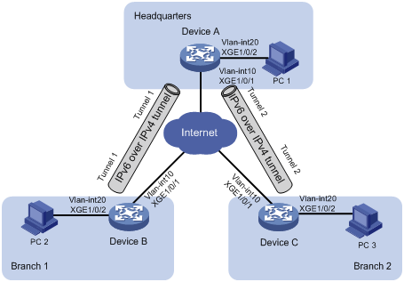
Table 1 Interface and IP address assignment
|
Device |
Interface |
IP address |
|
Device A |
Vlan-int10 |
20.1.1.1/24 |
|
|
Vlan-int20 |
2001::1/64 |
|
|
Tunnel1 |
3001::1/64 |
|
|
Tunnel2 |
4001::1/64 |
|
Device B |
Vlan-int10 |
30.1.1.1/24 |
|
|
Vlan-int20 |
5001::1/64 |
|
|
Tunnel1 |
3001::2/64 |
|
Device C |
Vlan-int10 |
40.1.1.1/24 |
|
|
Vlan-int20 |
6001::1/64 |
|
|
Tunnel2 |
4001::2/64 |
Applicable hardware and software versions
The following matrix shows the hardware and software versions to which this configuration example is applicable:
|
Hardware |
Software version |
|
S6520X-HI switch series S6520X-EI switch series |
Supported in Release 1110P01 |
|
S6520X-SI switch series S6520-SI switch series S5000-EI switch series MS4600 switch series |
Supported in Release 1110P01 |
Procedures
Make sure the gateways can reach each other at IPv4.
Configuring IPv6 over IPv4 tunnels
· Configure Device A:
# Configure an IP address for VLAN-interface 10.
<DeviceA> system-view
[DeviceA] vlan 10
[DeviceA-vlan10] port Ten-GigabitEthernet 1/0/1
[DeviceA-vlan10] quit
[DeviceA] interface vlan-interface 10
[DeviceA-Vlan-interface10] ip address 20.1.1.1 24
[DeviceA-Vlan-interface10] quit
# Configure IP addresses for other interfaces, as shown in Figure 1. (Details not shown.)
# Configure an IPv6 over IPv4 tunnel interface Tunnel 1.
[DeviceA] interface tunnel 1 mode ipv6-ipv4
# Configure an IPv6 address for Tunnel 1.
[DeviceA-Tunnel1] ipv6 address 3001::1/64
# Specify VLAN-interface 10 as the source interface of Tunnel 1.
[DeviceA-Tunnel1] source vlan-interface 10
# Specify the destination address for Tunnel 1.
[DeviceA-Tunnel1] destination 30.1.1.1
[DeviceA-Tunnel1] quit
# Configure an IPv6 over IPv4 tunnel interface Tunnel 2.
[DeviceA] interface tunnel 2 mode ipv6-ipv4
# Configure an IPv6 address for Tunnel 2.
[DeviceA-Tunnel2] ipv6 address 4001::1/64
# Specify VLAN-interface 10 as the source interface of Tunnel 2.
[DeviceA-Tunnel2] source Vlan-interface 10
# Specify the destination address for Tunnel 2.
[DeviceA-Tunnel2] destination 40.1.1.1
[DeviceA-Tunnel2] quit
· Configure Device B:
# Configure an IP address for VLAN-interface 10.
<DeviceB> system-view
[DeviceB] vlan 10
[DeviceB-vlan10] port Ten-GigabitEthernet 1/0/1
[DeviceB-vlan10] quit
[DeviceB] interface vlan-interface 10
[DeviceB-Vlan-interface10] ip address 30.1.1.1 24
[DeviceB-Vlan-interface10] quit
# Configure IP addresses for other interfaces, as shown in Figure 1. (Details not shown.)
# Configure an IPv6 over IPv4 tunnel interface Tunnel 1.
[DeviceB] interface tunnel 1 mode ipv6-ipv4
# Configure an IPv6 address for Tunnel 1.
[DeviceB-Tunnel1] ipv6 address 3001::2/64
# Specify VLAN-interface 10 as the source interface of Tunnel 1.
[DeviceB-Tunnel1] source vlan-interface 10
# Specify the destination address for Tunnel 1.
[DeviceB-Tunnel1] destination 20.1.1.1
[DeviceB-Tunnel1] quit
· Configure Device C:
# Configure an IP address for VLAN-interface 10.
<DeviceC> system-view
[DeviceC] vlan 10
[DeviceC-vlan10] port Ten-GigabitEthernet 1/0/1
[DeviceC-vlan10] quit
[DeviceC] interface vlan-interface 10
[DeviceC-Vlan-interface10] ip address 40.1.1.1 24
[DeviceC-Vlan-interface10] quit
# Configure IP addresses for other interfaces, as shown in Figure 1. (Details not shown.)
# Configure an IPv6 over IPv4 tunnel interface Tunnel 2.
[DeviceC] interface tunnel 2 mode ipv6-ipv4
# Configure an IPv6 address for Tunnel 2.
[DeviceC-Tunnel2] ipv6 address 4001::2/64
# Specify VLAN-interface 10 as the source interface of Tunnel 2.
[DeviceC-Tunnel2] source vlan-interface 10
# Specify the destination address for Tunnel 2.
[DeviceC-Tunnel2] destination 20.1.1.1
[DeviceC-Tunnel2] quit
Configuring OSPFv3
· Configure Device A:
# Specify the router ID as 1.1.1.1.
[DeviceA] ospfv3
[DeviceA-ospfv3-1] router-id 1.1.1.1
[DeviceA-ospfv3-1] quit
# Enable OSPFv3 on Tunnel 1.
[DeviceA] interface Tunnel 1
[DeviceA-Tunnel1] ospfv3 1 area 0
[DeviceA-Tunnel1] quit
# Enable OSPFv3 on Tunnel 2.
[DeviceA] interface Tunnel 2
[DeviceA-Tunnel2] ospfv3 1 area 0
[DeviceA-Tunnel2] quit
# Enable OSPFv3 on VLAN-interface 20.
[DeviceA] interface vlan-interface 20
[DeviceA-Vlan-interface20] ospfv3 1 area 0
[DeviceA-Vlan-interface20] quit
· Configure Device B:
# Specify the router ID as 2.2.2.2.
[DeviceB] ospfv3
[DeviceB-ospfv3-1] router-id 2.2.2.2
[DeviceB-ospfv3-1] quit
# Enable OSPFv3 on Tunnel 1.
[DeviceB] interface Tunnel 1
[DeviceB-Tunnel1] ospfv3 1 area 0
[DeviceB-Tunnel1] quit
# Enable OSPFv3 on VLAN-interface 20.
[DeviceB] interface vlan-interface 20
[DeviceB-Vlan-interface20] ospfv3 1 area 0
[DeviceB-Vlan-interface20] quit
· Configure Device C:
# Specify the router ID as 3.3.3.3.
[DeviceC] ospfv3
[DeviceC-ospfv3-1] router-id 3.3.3.3
[DeviceC-ospfv3-1] quit
# Enable OSPFv3 on Tunnel 2.
[DeviceC] interface Tunnel 2
[DeviceC-Tunnel2] ospfv3 1 area 0
[DeviceC-Tunnel2] quit
# Enable OSPFv3 on VLAN-interface 20.
[DeviceC] interface vlan-interface 20
[DeviceC-Vlan-interface20] ospfv3 1 area 0
[DeviceC-Vlan-interface20] quit
Verifying the configuration
# Ping PC 1 from PC 2.
Pinging 2001::3
from 5001::3 with 32 bytes of data:
Reply from 2001::3: bytes=32 time=13ms
Reply from 2001::3: bytes=32 time=1ms
Reply from 2001::3: bytes=32 time=1ms
Reply from 2001::3: bytes=32 time<1ms
Ping statistics for 2001::3:
Packets: Sent = 4, Received = 4, Lost = 0 (0% loss),
Approximate round trip times in milli-seconds:
Minimum = 0ms, Maximum = 13ms, Average = 3ms
The output shows that the ping operation succeeds.
# Ping PC 3 from PC 2.
D:\>ping6 -s 5001::3 6001::3
Pinging 6001::3
from 6001::3 with 32 bytes of data:
Reply from 6001::3: bytes=32 time=13ms
Reply from 6001::3: bytes=32 time=1ms
Reply from 6001::3: bytes=32 time=1ms
Reply from 6001::3: bytes=32 time<1ms
Ping statistics for 6001::3:
Packets: Sent = 4, Received = 4, Lost = 0 (0% loss),
Approximate round trip times in milli-seconds:
Minimum = 0ms, Maximum = 13ms, Average = 3ms
The output shows that the ping operation succeeds.
Configuration files
· Device A:
#
ospfv3 1
router-id 1.1.1.1
area 0.0.0.0
#
vlan 10
#
vlan 20
#
interface Vlan-interface10
ip address 20.1.1.1 255.255.255.0
#
interface Vlan-interface20
ospfv3 1 area 0.0.0.0
ipv6 address 2001::1/64
#
interface Ten-GigabitEthernet1/0/1
port link-mode bridge
port access vlan 10
#
interface Ten-GigabitEthernet1/0/2
port link-mode bridge
port access vlan 20
#
interface Tunnel1 mode ipv6-ipv4
ospfv3 1 area 0.0.0.0
source Vlan-interface10
destination 30.1.1.1
ipv6 address 3001::1/64
#
interface Tunnel2 mode ipv6-ipv4
ospfv3 1 area 0.0.0.0
source Vlan-interface10
destination 40.1.1.1
ipv6 address 4001::1/64
#
· Device B:
#
ospfv3 1
router-id 2.2.2.2
area 0.0.0.0
#
vlan 10
#
vlan 20
#
interface Vlan-interface10
ip address 30.1.1.1 255.255.255.0
#
interface Vlan-interface20
ospfv3 1 area 0.0.0.0
ipv6 address 5001::1/64
#
interface Ten-GigabitEthernet1/0/1
port link-mode bridge
port access vlan 10
#
interface Ten-GigabitEthernet1/0/2
port link-mode bridge
port access vlan 20
#
interface Tunnel1 mode ipv6-ipv4
ospfv3 1 area 0.0.0.0
source Vlan-interface10
destination 20.1.1.1
ipv6 address 3001::2/64
#
· Device C:
#
ospfv3 1
router-id 3.3.3.3
area 0.0.0.0
#
vlan 10
#
vlan 20
#
interface Vlan-interface10
ip address 40.1.1.1 255.255.255.0
#
interface Vlan-interface20
ospfv3 1 area 0.0.0.0
ipv6 address 6001::1/64
#
interface Ten-GigabitEthernet1/0/1
port link-mode bridge
port access vlan 10
#
interface Ten-GigabitEthernet1/0/2
port link-mode bridge
port access vlan 20
#
interface Tunnel2 mode ipv6-ipv4
ospfv3 1 area 0.0.0.0
source Vlan-interface10
destination 20.1.1.1
ipv6 address 4001::2/64
#