- Table of Contents
-
- H3C Fixed Port Campus Switches Configuration Examples-B70D029-6W100
- 01-Login Management Configuration Examples
- 02-RBAC Configuration Examples
- 03-Software Upgrade Examples
- 04-ISSU Configuration Examples
- 05-Software Patching Examples
- 06-Ethernet Link Aggregation Configuration Examples
- 07-Port Isolation Configuration Examples
- 08-Spanning Tree Configuration Examples
- 09-VLAN Configuration Examples
- 10-VLAN Tagging Configuration Examples
- 11-DHCP Snooping Configuration Examples
- 12-Cross-Subnet Dynamic IP Address Allocation Configuration Examples
- 13-IPv6 over IPv4 Tunneling with OSPFv3 Configuration Examples
- 14-IPv6 over IPv4 GRE Tunnel Configuration Examples
- 15-GRE with OSPF Configuration Examples
- 16-OSPF Configuration Examples
- 17-IS-IS Configuration Examples
- 18-BGP Configuration Examples
- 19-Policy-Based Routing Configuration Examples
- 20-OSPFv3 Configuration Examples
- 21-IPv6 IS-IS Configuration Examples
- 22-Routing Policy Configuration Examples
- 23-IGMP Snooping Configuration Examples
- 24-IGMP Configuration Examples
- 25-MLD Snooping Configuration Examples
- 26-IPv6 Multicast VLAN Configuration Examples
- 27-ACL Configuration Examples
- 28-Traffic Policing Configuration Examples
- 29-GTS and Rate Limiting Configuration Examples
- 30-Priority Mapping and Queue Scheduling Configuration Examples
- 31-Traffic Filtering Configuration Examples
- 32-AAA Configuration Examples
- 33-Port Security Configuration Examples
- 34-Portal Configuration Examples
- 35-SSH Configuration Examples
- 36-IP Source Guard Configuration Examples
- 37-Ethernet OAM Configuration Examples
- 38-CFD Configuration Examples
- 39-DLDP Configuration Examples
- 40-VRRP Configuration Examples
- 41-BFD Configuration Examples
- 42-NTP Configuration Examples
- 43-SNMP Configuration Examples
- 44-NQA Configuration Examples
- 45-Mirroring Configuration Examples
- 46-sFlow Configuration Examples
- 47-OpenFlow Configuration Examples
- 48-MAC Address Table Configuration Examples
- 49-Static Multicast MAC Address Entry Configuration Examples
- 50-IP Unnumbered Configuration Examples
- 51-MVRP Configuration Examples
- 52-MCE Configuration Examples
- 53-Attack Protection Configuration Examples
- 54-Smart Link Configuration Examples
- 55-RRPP Configuration Examples
- 56-BGP Route Selection Configuration Examples
- 57-IS-IS Route Summarization Configuration Examples
- 58-IRF Configuration Examples
- 59-VXLAN Configuration Examples
- Related Documents
-
| Title | Size | Download |
|---|---|---|
| 54-Smart Link Configuration Examples | 223.73 KB |
General restrictions and guidelines
Example: Configuring Smart Link load sharing
Applicable hardware and software versions
Example: Configuring Smart Link and Monitor Link collaboration
Applicable hardware and software versions
Example: Configuring Smart Link in an IRF fabric
Applicable hardware and software versions
Introduction
This document provides Smart Link configuration examples.
Prerequisites
This document is not restricted to specific software or hardware versions.
The configuration examples in this document were created and verified in a lab environment, and all the devices were started with the factory default configuration. When you are working on a live network, make sure you understand the potential impact of every command on your network.
This document assumes that you have basic knowledge of Smart Link, Monitor Link, and IRF.
General restrictions and guidelines
If you configure a port as both an aggregation group member and a smart link group member, only the aggregation group configuration takes effect. The port is not shown in the output from the display smart-link group command.
Example: Configuring Smart Link load sharing
Network configuration
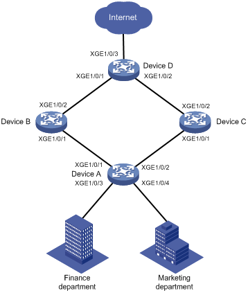
As shown in Figure 1, VLAN 10 and VLAN 11 are assigned to the Finance department and the Marketing department of an enterprise, respectively. Traffic of VLAN 10 and VLAN 11 on Device A is dually uplinked to Device D by Device B and Device C. Configure Smart Link to meet the following requirements:
· When the link between Device A and Device B and the link between Device A and Device C are both available, the traffic of the Finance department is forwarded trough the link between Device A and Device B. The traffic of the Marketing department is forwarded through the link between Device A and Device C.
· When one link fails, the traffic on the link is switched to another link. When the link recovers, the traffic is switched back to the link.
|
Device |
Interface |
VLAN |
Device |
Interface |
VLAN |
|
Device A |
XGE1/0/1 |
10, 11 |
Device C |
XGE1/0/1 |
10, 11 |
|
XGE1/0/2 |
10, 11 |
XGE1/0/2 |
10, 11 |
||
|
XGE1/0/3 |
10 |
Device D |
XGE1/0/1 |
10, 11 |
|
|
XGE1/0/4 |
11 |
XGE1/0/2 |
10, 11 |
||
|
Device B |
XGE1/0/1 |
10, 11 |
XGE1/0/3 |
10, 11 |
|
|
XGE1/0/2 |
10, 11 |
|
|
Analysis
To implement load sharing on the two uplinks, create two smart link groups with the same member ports on Device A. The role of each port must be different in the two smart link groups. Use the VLANs of the Finance department and Marketing department as the protected VLANs of the corresponding smart link groups.
For the traffic to switch back to the recovered link, enable role preemption for the two smart link groups.
For the upstream device to refresh MAC address entries and ARP/ND entries when link switchover occurs in a smart link group, perform the following tasks:
· Enable flush message sending on Device A.
· Enable flush message receiving on ports of the primary and secondary links from Device A to Device D.
Applicable hardware and software versions
The following matrix shows the hardware and software versions to which this configuration example is applicable:
|
Hardware |
Software version |
|
S6520X-HI switch series S6520X-EI switch series |
Supported in Release 1110P01 |
|
S6520X-SI switch series S6520-SI switch series S5000-EI switch series MS4600 switch series |
Supported in Release 1110P01 |
Restrictions and guidelines
When you configure Smart Link load sharing, follow these restrictions and guidelines:
· Before you configure a port as a smart link group member, shut down the port to prevent loops. You can bring up the port only after completing the smart link group configuration.
· Before you configure a smart link group member port or its directly connected port, disable the spanning tree feature and RRPP on the port.
· Make sure the receive control VLAN configured on the upstream device is the same as the transmit control VLAN configured on the smart link device.
· The control VLAN configured for a smart link group must be different from the control VLAN configured for any other smart link groups.
· The control VLAN of a smart link group must also be one of its protected VLANs. Do not remove the control VLAN. Otherwise, flush messages cannot be sent correctly.
Procedures
Configuring Device A
1. Create VLAN 10 and VLAN 11.
<DeviceA> system-view
[DeviceA] vlan 10 to 11
2. Configure Ten-GigabitEthernet 1/0/1:
# Shut down Ten-GigabitEthernet 1/0/1.
[DeviceA] interface ten-gigabitethernet 1/0/1
[DeviceA-Ten-GigabitEthernet1/0/1] shutdown
# Configure Ten-GigabitEthernet 1/0/1 as a trunk port.
[DeviceA-Ten-GigabitEthernet1/0/1] port link-type trunk
# Assign the port to VLAN 10 and VLAN 11.
[DeviceA-Ten-GigabitEthernet1/0/1] port trunk permit vlan 10 11
# Remove the port from VLAN 1.
[DeviceA-Ten-GigabitEthernet1/0/1] undo port trunk permit vlan 1
# Disable the spanning tree feature on the port.
[DeviceA-Ten-GigabitEthernet1/0/1] undo stp enable
[DeviceA-Ten-GigabitEthernet1/0/1] quit
3. Configure Ten-GigabitEthernet 1/0/2 in the same way Ten-GigabitEthernet 1/0/1 is configured.
[DeviceA] interface ten-gigabitethernet 1/0/2
[DeviceA-Ten-GigabitEthernet1/0/2] shutdown
[DeviceA-Ten-GigabitEthernet1/0/2] port link-type trunk
[DeviceA-Ten-GigabitEthernet1/0/2] port trunk permit vlan 10 11
[DeviceA-Ten-GigabitEthernet1/0/2] undo port trunk permit vlan 1
[DeviceA-Ten-GigabitEthernet1/0/2] undo stp enable
[DeviceA-Ten-GigabitEthernet1/0/2] quit
4. Configure Ten-GigabitEthernet 1/0/3:
# Configure Ten-GigabitEthernet 1/0/3 as an access port and assign the port to VLAN 10.
[DeviceA] interface ten-gigabitethernet 1/0/3
[DeviceA-Ten-GigabitEthernet1/0/3] port access vlan 10
# Bring up the port.
[DeviceA-Ten-GigabitEthernet1/0/3] undo shutdown
[DeviceA-Ten-GigabitEthernet1/0/3] quit
5. Configure Ten-GigabitEthernet 1/0/4:
# Configure Ten-GigabitEthernet 1/0/4 as an access port and assign the port to VLAN 11.
[DeviceA] interface ten-gigabitethernet 1/0/4
[DeviceA-Ten-GigabitEthernet1/0/4] port access vlan 11
# Bring up the port.
[DeviceA-Ten-GigabitEthernet1/0/4] undo shutdown
[DeviceA-Ten-GigabitEthernet1/0/4] quit
6. Configure VLAN-to-MSTI mappings and activate the MST region configuration:
# Enter MST region view.
[DeviceA] stp region-configuration
# Map VLAN 10 to MSTI 1, and VLAN 11 to MSTI 2.
[DeviceA-mst-region] instance 1 vlan 10
[DeviceA-mst-region] instance 2 vlan 11
# Activate the MST region configuration.
[DeviceA-mst-region] active region-configuration
[DeviceA-mst-region] quit
7. Configure smart link group 1:
# Create smart link group 1 and configure the VLAN mapped to MSTI 1, VLAN 10, as the protected VLAN.
[DeviceA] smart-link group 1
[DeviceA-smlk-group1] protected-vlan reference-instance 1
# Configure Ten-GigabitEthernet 1/0/1 as the primary port and Ten-GigabitEthernet 1/0/2 as the secondary port.
[DeviceA-smlk-group1] port ten-gigabitethernet 1/0/1 primary
[DeviceA-smlk-group1] port ten-gigabitethernet 1/0/2 secondary
# Enable flush message sending, and configure VLAN 10 as the transmit control VLAN.
[DeviceA-smlk-group1] flush enable control-vlan 10
# Enable role preemption and set the preemption delay to 10 seconds.
[DeviceA-smlk-group1] preemption mode role
[DeviceA-smlk-group1] preemption delay 10
[DeviceA-smlk-group1] quit
8. Configure smart link group 2:
# Create smart link group 2 and configure the VLAN mapped to MSTI 2, VLAN 11, as the protected VLAN.
[DeviceA] smart-link group 2
[DeviceA-smlk-group2] protected-vlan reference-instance 2
# Configure Ten-GigabitEthernet 1/0/2 as the primary port and Ten-GigabitEthernet 1/0/1 as the secondary port.
[DeviceA-smlk-group2] port ten-gigabitethernet 1/0/2 primary
[DeviceA-smlk-group2] port ten-gigabitethernet 1/0/1 secondary
# Enable flush message sending, and configure VLAN 11 as the transmit control VLAN.
[DeviceA-smlk-group2] flush enable control-vlan 11
# Enable role preemption and set the preemption delay to 10 seconds.
[DeviceA-smlk-group2] preemption mode role
[DeviceA-smlk-group2] preemption delay 10
[DeviceA-smlk-group2] quit
9. Bring up Ten-GigabitEthernet 1/0/1 and Ten-GigabitEthernet 1/0/2:
[DeviceA] interface ten-gigabitethernet 1/0/1
[DeviceA-Ten-GigabitEthernet1/0/1] undo shutdown
[DeviceA-Ten-GigabitEthernet1/0/1] quit
[DeviceA] interface ten-gigabitethernet 1/0/2
[DeviceA-Ten-GigabitEthernet1/0/2] undo shutdown
[DeviceA-Ten-GigabitEthernet1/0/2] quit
Configuring Device B
1. Create VLAN 10 and VLAN 11.
<DeviceB> system-view
[DeviceB] vlan 10 to 11
2. Configure Ten-GigabitEthernet 1/0/1:
# Configure Ten-GigabitEthernet 1/0/1 as a trunk port.
[DeviceB] interface ten-gigabitethernet 1/0/1
[DeviceB-Ten-GigabitEthernet1/0/1] port link-type trunk
# Assign the port to VLAN 10 and VLAN 11.
[DeviceB-Ten-GigabitEthernet1/0/1] port trunk permit vlan 10 11
# Remove the port from VLAN 1.
[DeviceB-Ten-GigabitEthernet1/0/1] undo port trunk permit vlan 1
# Disable the spanning tree feature on the port.
[DeviceB-Ten-GigabitEthernet1/0/1] undo stp enable
# Enable flush message receiving and configure VLAN 10 and VLAN 11 as the receive control VLANs on the port.
[DeviceB-Ten-GigabitEthernet1/0/1] smart-link flush enable control-vlan 10 11
# Bring up the port.
[DeviceB-Ten-GigabitEthernet1/0/1] undo shutdown
[DeviceB-Ten-GigabitEthernet1/0/1] quit
3. Configure Ten-GigabitEthernet 1/0/2:
# Configure Ten-GigabitEthernet 1/0/2 as a trunk port.
[DeviceB] interface ten-gigabitethernet 1/0/2
[DeviceB-Ten-GigabitEthernet1/0/2] port link-type trunk
# Assign the port to VLAN 10 and VLAN 11.
[DeviceB-Ten-GigabitEthernet1/0/2] port trunk permit vlan 10 11
# Remove the port from VLAN 1.
[DeviceB-Ten-GigabitEthernet1/0/2] undo port trunk permit vlan 1
# Enable flush message receiving and configure VLAN 10 and VLAN 11 as the receive control VLANs on the port.
[DeviceB-Ten-GigabitEthernet1/0/2] smart-link flush enable control-vlan 10 11
# Bring up the port.
[DeviceB-Ten-GigabitEthernet1/0/2] undo shutdown
[DeviceB-Ten-GigabitEthernet1/0/2] quit
Configuring Device C
1. Create VLAN 10 and VLAN 11.
<DeviceC> system-view
[DeviceC] vlan 10 to 11
2. Configure Ten-GigabitEthernet 1/0/1:
# Configure Ten-GigabitEthernet 1/0/1 as a trunk port.
[DeviceC] interface ten-gigabitethernet 1/0/1
[DeviceC-Ten-GigabitEthernet1/0/1] port link-type trunk
# Assign the port to VLAN 10 and VLAN 11.
[DeviceC-Ten-GigabitEthernet1/0/1] port trunk permit vlan 10 11
# Remove the port from VLAN 1.
[DeviceC-Ten-GigabitEthernet1/0/1] undo port trunk permit vlan 1
# Disable the spanning tree feature on the port.
[DeviceC-Ten-GigabitEthernet1/0/1] undo stp enable
# Enable flush message receiving and configure VLAN 10 and VLAN 11 as the receive control VLANs on the port.
[DeviceC-Ten-GigabitEthernet1/0/1] smart-link flush enable control-vlan 10 11
# Bring up the port.
[DeviceC-Ten-GigabitEthernet1/0/1] undo shutdown
[DeviceC-Ten-GigabitEthernet1/0/1] quit
3. Configure Ten-GigabitEthernet 1/0/2:
# Configure Ten-GigabitEthernet 1/0/2 as a trunk port.
[DeviceC] interface ten-gigabitethernet 1/0/2
[DeviceC-Ten-GigabitEthernet1/0/2] port link-type trunk
# Assign the port to VLAN 10 and VLAN 11.
[DeviceC-Ten-GigabitEthernet1/0/2] port trunk permit vlan 10 11
# Remove the port from VLAN 1.
[DeviceC-Ten-GigabitEthernet1/0/2] undo port trunk permit vlan 1
# Enable flush message receiving and configure VLAN 10 and VLAN 11 as the receive control VLANs on the port.
[DeviceC-Ten-GigabitEthernet1/0/2] smart-link flush enable control-vlan 10 11
# Bring up the port.
[DeviceC-Ten-GigabitEthernet1/0/2] undo shutdown
[DeviceC-Ten-GigabitEthernet1/0/2] quit
Configuring Device D
1. Create VLAN 10 and VLAN 11.
<DeviceD> system-view
[DeviceD] vlan 10 to 11
2. Configure Ten-GigabitEthernet 1/0/1:
# Configure Ten-GigabitEthernet 1/0/1 as a trunk port.
[DeviceD] interface ten-gigabitethernet 1/0/1
[DeviceD-Ten-GigabitEthernet1/0/1] port link-type trunk
# Assign the port to VLAN 10 and VLAN 11.
[DeviceD-Ten-GigabitEthernet1/0/1] port trunk permit vlan 10 11
# Remove the port from VLAN 1.
[DeviceD-Ten-GigabitEthernet1/0/1] undo port trunk permit vlan 1
# Enable flush message receiving and configure VLAN 10 and VLAN 11 as the receive control VLANs on the port.
[DeviceD-Ten-GigabitEthernet1/0/1] smart-link flush enable control-vlan 10 11
# Bring up the port.
[DeviceD-Ten-GigabitEthernet1/0/1] undo shutdown
[DeviceD-Ten-GigabitEthernet1/0/1] quit
3. Configure Ten-GigabitEthernet 1/0/2 in the same way Ten-GigabitEthernet 1/0/1 is configured.
[DeviceD] interface ten-gigabitethernet 1/0/2
[DeviceD-Ten-GigabitEthernet1/0/2] port link-type trunk
[DeviceD-Ten-GigabitEthernet1/0/2] port trunk permit vlan 10 11
[DeviceD-Ten-GigabitEthernet1/0/2] undo port trunk permit vlan 1
[DeviceD-Ten-GigabitEthernet1/0/2] smart-link flush enable control-vlan 10 11
[DeviceD-Ten-GigabitEthernet1/0/2] undo shutdown
[DeviceD-Ten-GigabitEthernet1/0/2] quit
4. Configure Ten-GigabitEthernet 1/0/3:
# Configure Ten-GigabitEthernet 1/0/3 as a trunk port
[DeviceD] interface ten-gigabitethernet 1/0/3
[DeviceD-Ten-GigabitEthernet1/0/3] port link-type trunk
# Assign the port to VLAN 10 and VLAN 11.
[DeviceD-Ten-GigabitEthernet1/0/3] port trunk permit vlan 10 11
# Remove the port from VLAN 1.
[DeviceD-Ten-GigabitEthernet1/0/3] undo port trunk permit vlan 1
# Bring up the port.
[DeviceD-Ten-GigabitEthernet1/0/3] undo shutdown
[DeviceD-Ten-GigabitEthernet1/0/3] quit
Verifying the configuration
1. Verify the smart link group configuration when Device A is operating correctly:
# Display information about all smart link groups on Device A.
[DeviceA] display smart-link group all
Smart link group 1 information:
Device ID : 0000-fc00-2500
Preemption mode : Role
Preemption delay: 10(s)
Control VLAN : 10
Protected VLAN : Reference Instance 1
Member Role State Flush-count Last-flush-time
-----------------------------------------------------------------------------
XGE1/0/1 PRIMARY ACTIVE 0 NA
XGE1/0/2 SECONDARY STANDBY 2 16:22:40 2014/12/29
Smart link group 2 information:
Device ID : 0000-fc00-2500
Preemption mode : Role
Preemption delay: 10(s)
Control VLAN : 11
Protected VLAN : Reference Instance 2
Member Role State Flush-count Last-flush-time
-----------------------------------------------------------------------------
XGE1/0/2 PRIMARY ACTIVE 2 16:22:40 2014/12/29
XGE1/0/1 SECONDARY STANDBY 0 NA
The output shows the following information:
¡ In smart link group 1, the primary port Ten-GigabitEthernet 1/0/1 is active to transmit traffic from VLAN 10.
¡ In smart link group 2, the primary port Ten-GigabitEthernet 1/0/2 is active to transmit traffic from VLAN 11.
2. Verify the smart link group configuration when Ten-GigabitEthernet 1/0/1 on Device A is down:
# Display information about all smart link groups on Device A.
[DeviceA] display smart-link group all
Smart link group 1 information:
Device ID : 0000-fc00-2500
Preemption mode : Role
Preemption delay: 10(s)
Control VLAN : 10
Protected VLAN : Reference Instance 1
Member Role State Flush-count Last-flush-time
-----------------------------------------------------------------------------
XGE1/0/1 PRIMARY DOWN 0 NA
XGE1/0/2 SECONDARY ACTIVE 3 16:43:06 2014/12/29
Smart link group 2 information:
Device ID : 0000-fc00-2500
Preemption mode : Role
Preemption delay: 10(s)
Control VLAN : 11
Protected VLAN : Reference Instance 2
Member Role State Flush-count Last-flush-time
-----------------------------------------------------------------------------
XGE1/0/2 PRIMARY ACTIVE 2 16:22:40 2014/12/29
XGE1/0/1 SECONDARY DOWN 0 NA
The output shows the following information:
¡ In smart link group 1, the secondary port Ten-GigabitEthernet 1/0/2 is active to transmit traffic from VLAN 10.
¡ In smart link group 2, the primary port Ten-GigabitEthernet 1/0/2 remains active to transmit traffic from VLAN 11.
# Display information about the received flush messages on Device B.
[DeviceB] display smart-link flush
Received flush packets : 1
Receiving interface of the last flush packet : Ten-GigabitEthernet1/0/2
Receiving time of the last flush packet : 16:43:08 2014/10/29
Device ID of the last flush packet : 0000-fc00-2500
Control VLAN of the last flush packet : 10
Configuration files
· Device A:
#
vlan 1
#
vlan 10 to 11
#
stp region-configuration
instance 1 vlan 10
instance 2 vlan 11
active region-configuration
#
smart-link group 1
preemption mode role
preemption delay 10
flush enable control-vlan 10
protected-vlan reference-instance 1
#
smart-link group 2
preemption mode role
preemption delay 10
flush enable control-vlan 11
protected-vlan reference-instance 2
#
interface Ten-GigabitEthernet1/0/1
port link-mode bridge
port link-type trunk
undo port trunk permit vlan 1
port trunk permit vlan 10 to 11
undo stp enable
port smart-link group 1 primary
port smart-link group 2 secondary
#
interface Ten-GigabitEthernet1/0/2
port link-mode bridge
port link-type trunk
undo port trunk permit vlan 1
port trunk permit vlan 10 to 11
undo stp enable
port smart-link group 1 secondary
port smart-link group 2 primary
#
interface Ten-GigabitEthernet1/0/3
port link-mode bridge
port access vlan 10
#
interface Ten-GigabitEthernet1/0/4
port link-mode bridge
port access vlan 11
#
· Device B:
#
vlan 1
#
vlan 10 to 11
#
interface Ten-GigabitEthernet1/0/1
port link-mode bridge
port link-type trunk
undo port trunk permit vlan 1
port trunk permit vlan 10 to 11
undo stp enable
smart-link flush enable control-vlan 10 to 11
#
interface Ten-GigabitEthernet1/0/2
port link-mode bridge
port link-type trunk
undo port trunk permit vlan 1
port trunk permit vlan 10 to 11
smart-link flush enable control-vlan 10 to 11
#
· Device C:
#
vlan 1
#
vlan 10 to 11
#
interface Ten-GigabitEthernet1/0/1
port link-mode bridge
port link-type trunk
undo port trunk permit vlan 1
port trunk permit vlan 10 to 11
undo stp enable
smart-link flush enable control-vlan 10 to 11
#
interface Ten-GigabitEthernet1/0/2
port link-mode bridge
port link-type trunk
undo port trunk permit vlan 1
port trunk permit vlan 10 to 11
smart-link flush enable control-vlan 10 to 11
#
· Device D:
#
vlan 1
#
vlan 10 to 11
#
interface Ten-GigabitEthernet1/0/1
port link-mode bridge
port link-type trunk
undo port trunk permit vlan 1
port trunk permit vlan 10 to 11
smart-link flush enable control-vlan 10 to 11
#
interface Ten-GigabitEthernet1/0/2
port link-mode bridge
port link-type trunk
undo port trunk permit vlan 1
port trunk permit vlan 10 to 11
smart-link flush enable control-vlan 10 to 11
#
interface Ten-GigabitEthernet1/0/3
port link-mode bridge
port link-type trunk
undo port trunk permit vlan 1
port trunk permit vlan 10 to 11
#
Example: Configuring Smart Link and Monitor Link collaboration
Network configuration
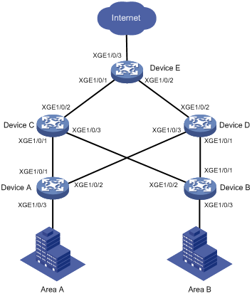
As shown in Figure 2, VLAN 10 and VLAN 11 are assigned to Zone A and Zone B, respectively. Traffic of VLAN 10 is dually uplinked from Device A to Device E by Device C and Device D. Traffic of VLAN 11 is dually uplinked from Device B to Device E by Device C and Device D. Configure Smart Link and Monitor Link to meet the following requirements:
· When the link between Device A and Device C and the link between Device A and Device D are both available, the traffic of Zone A is forwarded trough the link between Device A and Device C. When the link between Device A and Device C fails, the traffic is switched to the link between Device A and Device D. When the link between Device A and Device C recovers, the traffic switches back to the link.
· When the link between Device B and Device C and the link between Device B and Device D are both available, the traffic of Zone B is forwarded trough the link between Device B and Device D. When the link between Device B and Device D fails, the traffic is switched to the link between Device B and Device C. When the link between Device B and Device D recovers, the traffic switches back to the link.
· Configure Monitor Link on Device C and Device D to associate the state of downlink interfaces with the state of uplink interfaces. When Monitor link shuts down the downlink interfaces because of an uplink failure, Smart Link triggers a link switchover.
|
Device |
Interface |
VLAN |
Device |
Interface |
VLAN |
|
Device A |
XGE1/0/1 |
10 |
Device D |
XGE1/0/1 |
11 |
|
XGE1/0/2 |
10 |
XGE1/0/2 |
10, 11 |
||
|
XGE1/0/3 |
10 |
XGE1/0/3 |
10 |
||
|
Device B |
XGE1/0/1 |
11 |
Device E |
XGE1/0/1 |
10, 11 |
|
XGE1/0/2 |
11 |
XGE1/0/2 |
10, 11 |
||
|
XGE1/0/3 |
11 |
XGE1/0/3 |
10, 11 |
||
|
Device C |
XGE1/0/1 |
10 |
|
|
|
|
XGE1/0/2 |
10, 11 |
|
|
|
|
|
XGE1/0/3 |
11 |
|
|
|
Analysis
To implement dual uplink backup on Device A and Device B, perform the following tasks:
· Create a smart link group on Device A and Device B, respectively.
· Configure the VLANs of Zone A and Zone B as the protected VLANs of the corresponding smart link groups.
For the traffic to switch back to the recovered link, enable role preemption for the two smart link groups.
For the upstream device to refresh MAC address forwarding entries and ARP/ND entries when link switchover occurs in a smart link group, perform the following tasks:
· Enable flush message sending on Device A and Device B.
· Enable flush message receiving on the downlink ports on Device C and Device D.
Applicable hardware and software versions
The following matrix shows the hardware and software versions to which this configuration example is applicable:
|
Hardware |
Software version |
|
S6520X-HI switch series S6520X-EI switch series |
Supported in Release 1110P01 |
|
S6520X-SI switch series S6520-SI switch series S5000-EI switch series MS4600 switch series |
Supported in Release 1110P01 |
Restrictions and guidelines
When you configure Smart Link and Monitor Link collaboration, follow these restrictions and guidelines:
· Before you configure a port as a smart link group member, shut down the port to prevent loops. You can bring up the port only after completing the smart link group configuration.
· Before you configure a smart link group member port or its directly connected port, disable the spanning tree feature and RRPP on the port.
· Make sure the receive control VLAN configured on the upstream device is the same as the transmit control VLAN configured on the smart link device.
· The control VLAN configured for a smart link group must be different from the control VLAN configured for any other smart link groups.
· The control VLAN of a smart link group must also be one of its protected VLANs. Do not remove the control VLAN. Otherwise, flush messages cannot be sent correctly.
· You can assign a port to only one monitor link group.
· Do not use the shutdown command or the undo shutdown command to change the state of the downlink interfaces in a monitor link group.
Procedures
Configuring Device A
1. Create VLAN 10 and VLAN 11.
<DeviceA> system-view
[DeviceA] vlan 10 to 11
2. Configure Ten-GigabitEthernet 1/0/1:
# Shut down Ten-GigabitEthernet 1/0/1.
[DeviceA] interface ten-gigabitethernet 1/0/1
[DeviceA-Ten-GigabitEthernet1/0/1] shutdown
# Configure Ten-GigabitEthernet 1/0/1 as a trunk port.
[DeviceA-Ten-GigabitEthernet1/0/1] port link-type trunk
# Assign the port to VLAN 10.
[DeviceA-Ten-GigabitEthernet1/0/1] port trunk permit vlan 10
# Remove the port from VLAN 1.
[DeviceA-Ten-GigabitEthernet1/0/1] undo port trunk permit vlan 1
# Disable the spanning tree feature on the port.
[DeviceA-Ten-GigabitEthernet1/0/1] undo stp enable
[DeviceA-Ten-GigabitEthernet1/0/1] quit
3. Configure Ten-GigabitEthernet 1/0/2 in the same way Ten-GigabitEthernet 1/0/1 is configured.
[DeviceA] interface ten-gigabitethernet 1/0/2
[DeviceA-Ten-GigabitEthernet1/0/2] shutdown
[DeviceA-Ten-GigabitEthernet1/0/2] port link-type trunk
[DeviceA-Ten-GigabitEthernet1/0/2] port trunk permit vlan 10
[DeviceA-Ten-GigabitEthernet1/0/2] undo port trunk permit vlan 1
[DeviceA-Ten-GigabitEthernet1/0/2] undo stp enable
[DeviceA-Ten-GigabitEthernet1/0/2] quit
4. Configure Ten-GigabitEthernet 1/0/3:
# Configure Ten-GigabitEthernet 1/0/3 as an access port and assign the port to VLAN 10.
[DeviceA] interface ten-gigabitethernet 1/0/3
[DeviceA-Ten-GigabitEthernet1/0/3] port access vlan 10
# Bring up the port.
[DeviceA-Ten-GigabitEthernet1/0/3] undo shutdown
[DeviceA-Ten-GigabitEthernet1/0/3] quit
5. Configure VLAN-to-MSTI mappings and activate the MST region configuration:
# Enter MST region view.
[DeviceA] stp region-configuration
# Map VLAN 10 to MSTI 1.
[DeviceA-mst-region] instance 1 vlan 10
# Activate the MST region configuration.
[DeviceA-mst-region] active region-configuration
[DeviceA-mst-region] quit
6. Configure smart link group 1:
# Create smart link group 1 and configure the VLAN mapped to MSTI 1, VLAN 10, as the protected VLAN.
[DeviceA] smart-link group 1
[DeviceA-smlk-group1] protected-vlan reference-instance 1
# Configure Ten-GigabitEthernet 1/0/1 as the primary port and Ten-GigabitEthernet 1/0/2 as the secondary port.
[DeviceA-smlk-group1] port ten-gigabitethernet 1/0/1 primary
[DeviceA-smlk-group1] port ten-gigabitethernet 1/0/2 secondary
# Enable flush message sending, and configure VLAN 10 as the transmit control VLAN.
[DeviceA-smlk-group1] flush enable control-vlan 10
# Enable role preemption and set the preemption delay to 10 seconds.
[DeviceA-smlk-group1] preemption mode role
[DeviceA-smlk-group1] preemption delay 10
[DeviceA-smlk-group1] quit
7. Bring up Ten-GigabitEthernet 1/0/1 and Ten-GigabitEthernet 1/0/2:
[DeviceA] interface ten-gigabitethernet 1/0/1
[DeviceA-Ten-GigabitEthernet1/0/1] undo shutdown
[DeviceA-Ten-GigabitEthernet1/0/1] quit
[DeviceA] interface ten-gigabitethernet 1/0/2
[DeviceA-Ten-GigabitEthernet1/0/2] undo shutdown
[DeviceA-Ten-GigabitEthernet1/0/2] quit
Configuring Device B
1. Create VLAN 10 and VLAN 11.
<DeviceB> system-view
[DeviceB] vlan 10 to 11
2. Configure Ten-GigabitEthernet 1/0/1:
# Shut down Ten-GigabitEthernet 1/0/1.
[DeviceB] interface ten-gigabitethernet 1/0/1
[DeviceB-Ten-GigabitEthernet1/0/1] shutdown
# Configure Ten-GigabitEthernet 1/0/1 as a trunk port.
[DeviceB-Ten-GigabitEthernet1/0/1] port link-type trunk
# Assign the port to VLAN 11.
[DeviceB-Ten-GigabitEthernet1/0/1] port trunk permit vlan 11
# Remove the port from VLAN 1.
[DeviceB-Ten-GigabitEthernet1/0/1] undo port trunk permit vlan 1
# Disable the spanning tree feature on the port.
[DeviceB-Ten-GigabitEthernet1/0/1] undo stp enable
[DeviceB-Ten-GigabitEthernet1/0/1] quit
3. Configure Ten-GigabitEthernet 1/0/2 in the same way Ten-GigabitEthernet 1/0/1 is configured.
[DeviceB] interface ten-gigabitethernet 1/0/2
[DeviceB-Ten-GigabitEthernet1/0/2] shutdown
[DeviceB-Ten-GigabitEthernet1/0/2] port link-type trunk
[DeviceB-Ten-GigabitEthernet1/0/2] port trunk permit vlan 11
[DeviceB-Ten-GigabitEthernet1/0/2] undo port trunk permit vlan 1
[DeviceB-Ten-GigabitEthernet1/0/2] undo stp enable
[DeviceB-Ten-GigabitEthernet1/0/2] quit
4. Configure Ten-GigabitEthernet 1/0/3:
# Configure Ten-GigabitEthernet 1/0/3 as an access port and assign the port to VLAN 11.
[DeviceB] interface ten-gigabitethernet 1/0/3
[DeviceB-Ten-GigabitEthernet1/0/3] port access vlan 11
# Bring up the port.
[DeviceB-Ten-GigabitEthernet1/0/3] undo shutdown
[DeviceB-Ten-GigabitEthernet1/0/3] quit
5. Configure VLAN-to-MSTI mappings and activate the MST region configuration:
# Enter MST region view.
[DeviceB] stp region-configuration
# Map VLAN 11 to MSTI 1.
[DeviceB-mst-region] instance 1 vlan 11
# Activate the MST region configuration
[DeviceB-mst-region] active region-configuration
[DeviceB-mst-region] quit
6. Configure smart link group 1.
# Create smart link group 1 and configure the VLAN mapped to MSTI 1, VLAN 11, as the protected VLAN.
[DeviceB] smart-link group 1
[DeviceB-smlk-group1] protected-vlan reference-instance 1
# Configure Ten-GigabitEthernet 1/0/1 as the primary port and Ten-GigabitEthernet 1/0/2 as the secondary port.
[DeviceB-smlk-group1] port ten-gigabitethernet 1/0/1 primary
[DeviceB-smlk-group1] port ten-gigabitethernet 1/0/2 secondary
# Enable flush message sending, and configure VLAN 11 as the transmit control VLAN.
[DeviceA-smlk-group1] flush enable control-vlan 11
# Enable role preemption and set the preemption delay to 10 seconds.
[DeviceB-smlk-group1] preemption mode role
[DeviceB-smlk-group1] preemption delay 10
[DeviceB-smlk-group1] quit
7. Bring up Ten-GigabitEthernet 1/0/1 and Ten-GigabitEthernet 1/0/2:
[DeviceB] interface ten-gigabitethernet 1/0/1
[DeviceB-Ten-GigabitEthernet1/0/1] undo shutdown
[DeviceB-Ten-GigabitEthernet1/0/1] quit
[DeviceB] interface ten-gigabitethernet 1/0/2
[DeviceB-Ten-GigabitEthernet1/0/2] undo shutdown
[DeviceB-Ten-GigabitEthernet1/0/2] quit
Configuring Device C
1. Create VLAN 10 and VLAN 11.
<DeviceC> system-view
[DeviceC] vlan 10 to 11
2. Configure Ten-GigabitEthernet 1/0/1:
# Configure Ten-GigabitEthernet 1/0/1 as a trunk port.
[DeviceC] interface ten-gigabitethernet 1/0/1
[DeviceC-Ten-GigabitEthernet1/0/1] port link-type trunk
# Assign the port to VLAN 10.
[DeviceC-Ten-GigabitEthernet1/0/1] port trunk permit vlan 10
# Remove the port from VLAN 1.
[DeviceC-Ten-GigabitEthernet1/0/1] undo port trunk permit vlan 1
# Disable the spanning tree feature on the port.
[DeviceC-Ten-GigabitEthernet1/0/1] undo stp enable
# Enable flush message receiving and configure VLAN 10 as the receive control VLAN on the port.
[DeviceC-Ten-GigabitEthernet1/0/1] smart-link flush enable control-vlan 10
# Bring up the port.
[DeviceC-Ten-GigabitEthernet1/0/1] undo shutdown
[DeviceC-Ten-GigabitEthernet1/0/1] quit
3. Configure Ten-GigabitEthernet 1/0/2:
# Configure Ten-GigabitEthernet 1/0/2 as a trunk port.
[DeviceC] interface ten-gigabitethernet 1/0/2
[DeviceC-Ten-GigabitEthernet1/0/2] port link-type trunk
# Assign the port to VLAN 10 and VLAN 11.
[DeviceC-Ten-GigabitEthernet1/0/2] port trunk permit vlan 10 11
# Remove the port from VLAN 1.
[DeviceC-Ten-GigabitEthernet1/0/2] undo port trunk permit vlan 1
# Enable flush message receiving and configure VLAN 10 and VLAN 11 as the receive control VLANs on the port.
[DeviceC-Ten-GigabitEthernet1/0/2] smart-link flush enable control-vlan 10 11
# Bring up the port.
[DeviceC-Ten-GigabitEthernet1/0/2] undo shutdown
[DeviceC-Ten-GigabitEthernet1/0/2] quit
4. Configure Ten-GigabitEthernet 1/0/3:
# Configure Ten-GigabitEthernet 1/0/3 as a trunk port.
[DeviceC] interface ten-gigabitethernet 1/0/3
[DeviceC-Ten-GigabitEthernet1/0/3] port link-type trunk
# Assign the port to VLAN 11.
[DeviceC-Ten-GigabitEthernet1/0/3] port trunk permit vlan 11
# Remove the port from VLAN 1.
[DeviceC-Ten-GigabitEthernet1/0/3] undo port trunk permit vlan 1
# Disable the spanning tree feature on the port.
[DeviceC-Ten-GigabitEthernet1/0/3] undo stp enable
# Enable flush message receiving and configure VLAN 11 as the receive control VLAN on the port.
[DeviceC-Ten-GigabitEthernet1/0/3] smart-link flush enable control-vlan 11
# Bring up the port.
[DeviceB-Ten-GigabitEthernet1/0/3] undo shutdown
[DeviceB-Ten-GigabitEthernet1/0/3] quit
5. Configure monitor link group 1:
# Create monitor link group 1.
[DeviceC] monitor-link group 1
# Configure the uplink interface threshold for triggering monitor link group state switchover as 1.
[DeviceC-mtlk-group1] uplink up-port-threshold 1
# Configure Ten-GigabitEthernet 1/0/2 as the uplink port and Ten-GigabitEthernet 1/0/1 and Ten-GigabitEthernet 1/0/3 as the downlink ports.
[DeviceC-mtlk-group1] port ten-gigabitethernet 1/0/2 uplink
[DeviceC-mtlk-group1] port ten-gigabitethernet 1/0/1 downlink
[DeviceC-mtlk-group1] port ten-gigabitethernet 1/0/3 downlink
[DeviceC-mtlk-group1] quit
Configuring Device D
1. Create VLAN 10 and VLAN 11.
<DeviceD> system-view
[DeviceD] vlan 10 to 11
2. Configure Ten-GigabitEthernet 1/0/1:
# Configure Ten-GigabitEthernet 1/0/1 as a trunk port.
[DeviceD] interface ten-gigabitethernet 1/0/1
[DeviceD-Ten-GigabitEthernet1/0/1] port link-type trunk
# Assign the port to VLAN 11.
[DeviceD-Ten-GigabitEthernet1/0/1] port trunk permit vlan 11
# Remove the port from VLAN 1.
[DeviceD-Ten-GigabitEthernet1/0/1] undo port trunk permit vlan 1
# Disable the spanning tree feature on the port.
[DeviceD-Ten-GigabitEthernet1/0/1] undo stp enable
# Enable flush message receiving and configure VLAN 11 as the receive control VLAN on the port.
[DeviceD-Ten-GigabitEthernet1/0/1] smart-link flush enable control-vlan 11
# Bring up the port.
[DeviceD-Ten-GigabitEthernet1/0/1] undo shutdown
[DeviceD-Ten-GigabitEthernet1/0/1] quit
3. Configure Ten-GigabitEthernet 1/0/2:
# Configure Ten-GigabitEthernet 1/0/2 as a trunk port.
[DeviceD] interface ten-gigabitethernet 1/0/2
[DeviceD-Ten-GigabitEthernet1/0/2] port link-type trunk
# Assign the port to VLAN 10 and VLAN 11.
[DeviceD-Ten-GigabitEthernet1/0/2] port trunk permit vlan 10 11
# Remove the port from VLAN 1.
[DeviceD-Ten-GigabitEthernet1/0/2] undo port trunk permit vlan 1
# Enable flush message receiving and configure VLAN 10 and VLAN 11 as the receive control VLANs on the port.
[DeviceD-Ten-GigabitEthernet1/0/2] smart-link flush enable control-vlan 10 11
# Bring up the port.
[DeviceD-Ten-GigabitEthernet1/0/2] undo shutdown
[DeviceD-Ten-GigabitEthernet1/0/2] quit
4. Configure Ten-GigabitEthernet 1/0/3:
# Configure Ten-GigabitEthernet 1/0/3 as a trunk port.
[DeviceD] interface ten-gigabitethernet 1/0/3
[DeviceD-Ten-GigabitEthernet1/0/3] port link-type trunk
# Assign the port to VLAN 10.
[DeviceD-Ten-GigabitEthernet1/0/3] port trunk permit vlan 10
# Remove the port from VLAN 1.
[DeviceD-Ten-GigabitEthernet1/0/3] undo port trunk permit vlan 1
# Disable the spanning tree feature on the port.
[DeviceD-Ten-GigabitEthernet1/0/3] undo stp enable
# Enable flush message receiving and configure VLAN 10 as the receive control VLAN on the port.
[DeviceD-Ten-GigabitEthernet1/0/3] smart-link flush enable control-vlan 10
# Bring up the port.
[DeviceD-Ten-GigabitEthernet1/0/3] undo shutdown
[DeviceD-Ten-GigabitEthernet1/0/3] quit
5. Configure monitor link group 1:
# Create monitor link group 1.
[DeviceD] monitor-link group 1
# Configure the uplink interface threshold for triggering monitor link group state switchover as 1.
[DeviceD-mtlk-group1] uplink up-port-threshold 1
# Configure Ten-GigabitEthernet 1/0/2 as the uplink port and Ten-GigabitEthernet 1/0/1 and Ten-GigabitEthernet 1/0/3 as the downlink ports.
[DeviceD-mtlk-group1] port ten-gigabitethernet 1/0/2 uplink
[DeviceD-mtlk-group1] port ten-gigabitethernet 1/0/1 downlink
[DeviceD-mtlk-group1] port ten-gigabitethernet 1/0/3 downlink
[DeviceD-mtlk-group1] quit
Configuring Device E
1. Create VLAN 10 and VLAN 11.
<DeviceE> system-view
[DeviceE] vlan 10 to 11
2. Configure Ten-GigabitEthernet 1/0/1:
# Configure Ten-GigabitEthernet 1/0/1 as a trunk port.
[DeviceE] interface ten-gigabitethernet 1/0/1
[DeviceE-Ten-GigabitEthernet1/0/1] port link-type trunk
# Assign the port to VLAN 10 and VLAN 11.
[DeviceE-Ten-GigabitEthernet1/0/1] port trunk permit vlan 10 11
# Remove the port from VLAN 1.
[DeviceE-Ten-GigabitEthernet1/0/1] undo port trunk permit vlan 1
# Enable flush message receiving and configure VLAN 10 and VLAN 11 as the receive control VLANs on the port.
[DeviceE-Ten-GigabitEthernet1/0/1] smart-link flush enable control-vlan 10 11
# Bring up the port.
[DeviceE-Ten-GigabitEthernet1/0/1] undo shutdown
[DeviceE-Ten-GigabitEthernet1/0/1] quit
3. Configure Ten-GigabitEthernet 1/0/2 in the same way Ten-GigabitEthernet 1/0/1 is configured.
[DeviceE] interface ten-gigabitethernet 1/0/2
[DeviceE-Ten-GigabitEthernet1/0/2] port link-type trunk
[DeviceE-Ten-GigabitEthernet1/0/2] port trunk permit vlan 10 11
[DeviceE-Ten-GigabitEthernet1/0/2] undo port trunk permit vlan 1
[DeviceE-Ten-GigabitEthernet1/0/2] smart-link flush enable control-vlan 10 11
[DeviceE-Ten-GigabitEthernet1/0/2] undo shutdown
[DeviceE-Ten-GigabitEthernet1/0/2] quit
4. Configure Ten-GigabitEthernet 1/0/3:
# Configure Ten-GigabitEthernet 1/0/3 as a trunk port.
[DeviceE] interface ten-gigabitethernet 1/0/3
[DeviceE-Ten-GigabitEthernet1/0/3] port link-type trunk
# Assign the port to VLAN 10 and VLAN 11.
[DeviceE-Ten-GigabitEthernet1/0/3] port trunk permit vlan 10 11
# Remove the port from VLAN 1.
[DeviceE-Ten-GigabitEthernet1/0/3] undo port trunk permit vlan 1
# Bring up the port.
[DeviceE-Ten-GigabitEthernet1/0/3] undo shutdown
[DeviceE-Ten-GigabitEthernet1/0/3] quit
Verifying the configuration
1. Verify the smart link group configuration when Device A and Device B are operating correctly:
# Display information about all smart link groups on Device A.
[DeviceA] display smart-link group all
Smart link group 1 information:
Device ID : 0000-fc00-2500
Preemption mode : Role
Preemption delay: 10(s)
Control VLAN : 10
Protected VLAN : Reference Instance 1
Member Role State Flush-count Last-flush-time
-----------------------------------------------------------------------------
XGE1/0/1 PRIMARY ACTIVE 1 17:37:49 2014/12/29
XGE1/0/2 SECONDARY STANDBY 3 17:43:06 2014/12/29
The output shows that in smart link group 1, the primary port Ten-GigabitEthernet 1/0/1 is active to transmit traffic from VLAN 10.
# Display information about all smart link groups on Device B.
[DeviceB] display smart-link group all
Smart link group 1 information:
Device ID : 0000-fc01-2501
Preemption mode : Role
Preemption delay: 10(s)
Control VLAN : 11
Protected VLAN : Reference Instance 2
Member Role State Flush-count Last-flush-time
-----------------------------------------------------------------------------
XGE1/0/1 PRIMARY ACTIVE 2 17:22:40 2014/12/29
XGE1/0/2 SECONDARY STANDBY 0 NA
The output shows that in smart link group 1, the primary port Ten-GigabitEthernet 1/0/1 is active to transmit traffic from VLAN 11.
2. Verify the monitor link group configuration when Device C and Device D are operating correctly:
# Display information about all monitor link groups on Device C.
[DeviceC] display monitor-link group all
Monitor link group 1 information:
Group status : UP
Downlink up-delay: 0(s)
Last-up-time : 17:07:26 2014/12/29
Last-down-time : -
Up-port-threshold: 1
Member Role Status
--------------------------------------------
XGE1/0/2 UPLINK UP
XGE1/0/1 DOWNLINK UP
XGE1/0/3 DOWNLINK UP
The output shows that in monitor link group 1, the uplink port Ten-GigabitEthernet 1/0/2 is up, and the downlink ports Ten-GigabitEthernet 1/0/1 and Ten-GigabitEthernet 1/0/3 are up.
# Display information about all monitor link groups on Device D.
[DeviceD] display monitor-link group all
Monitor link group 1 information:
Group status : UP
Downlink up-delay: 0(s)
Last-up-time : 17:09:33 2014/12/29
Last-down-time : -
Up-port-threshold: 1
Member Role Status
--------------------------------------------
XGE1/0/2 UPLINK UP
XGE1/0/1 DOWNLINK UP
XGE1/0/1 DOWNLINK UP
The output shows that in monitor link group 1, the uplink port Ten-GigabitEthernet 1/0/2 is up, and the downlink ports Ten-GigabitEthernet 1/0/1 and Ten-GigabitEthernet 1/0/3 are up.
3. Verify the smart link group configuration when Ten-GigabitEthernet 1/0/1 on Device A is down:
# Display information about all smart link groups on Device A.
[DeviceA] display smart-link group all
Smart link group 1 information:
Device ID : 0000-fc00-2500
Preemption mode : Role
Preemption delay: 10(s)
Control VLAN : 10
Protected VLAN : Reference Instance 1
Member Role State Flush-count Last-flush-time
-----------------------------------------------------------------------------
XGE1/0/1 PRIMARY DOWN 1 17:37:49 2014/12/29
XGE1/0/2 SECONDARY ACTIVE 4 17:49:06 2014/12/29
The output shows that in smart link group 1, the secondary port Ten-GigabitEthernet 1/0/2 is active to transmit traffic from VLAN 10.
# Display information about the received flush messages on Device C.
[DeviceC] display smart-link flush
Received flush packets : 1
Receiving interface of the last flush packet : Ten-GigabitEthernet1/0/2
Receiving time of the last flush packet : 17:49:08 2014/12/29
Device ID of the last flush packet : 0000-fc00-2500
Control VLAN of the last flush packet : 10
4. Verify the monitor link group configuration when the uplink port Ten-GigabitEthernet1/0/2 on Device C is down:
# Display information about all monitor link groups on Device C.
[DeviceC] display monitor-link group all
Monitor link group 1 information:
Group status : DOWN
Downlink up-delay: 0(s)
Last-up-time : 17:07:26 2014/12/29
Last-down-time : 18:01:05 2014/12/29
Up-port-threshold: 1
Member Role Status
--------------------------------------------
XGE1/0/2 UPLINK DOWN
XGE1/0/1 DOWNLINK DOWN
XGE1/0/3 DOWNLINK DOWN
The output shows that monitor link group 1 is down, and the downlink ports Ten-GigabitEthernet 1/0/1 and Ten-GigabitEthernet 1/0/3 in monitor link group 1 are down.
# Display information about all monitor link groups on Device D.
[DeviceD] display monitor-link group all
Monitor link group 1 information:
Group status : UP
Downlink up-delay: 0(s)
Last-up-time : 17:09:33 2014/12/29
Last-down-time : -
Up-port-threshold: 1
Member Role Status
--------------------------------------------
XGE1/0/2 UPLINK UP
XGE1/0/1 DOWNLINK UP
XGE1/0/3 DOWNLINK UP
The output shows that monitor link group 1 is up, and the downlink ports Ten-GigabitEthernet 1/0/1 and Ten-GigabitEthernet 1/0/3 in monitor link group 1 are up.
# Display information about all smart link groups on Device A.
[DeviceA] display smart-link group all
Smart link group 1 information:
Device ID : 0000-fc00-2500
Preemption mode : Role
Preemption delay: 10(s)
Control VLAN : 10
Protected VLAN : Reference Instance 1
Member Role State Flush-count Last-flush-time
-----------------------------------------------------------------------------
XGE1/0/1 PRIMARY DOWN 2 17:57:49 2014/12/29
XGE1/0/2 SECONDARY ACTIVE 5 18:01:06 2014/12/29
The output shows that Ten-GigabitEthernet 1/0/1 on Device A is down. In smart link group 1, the secondary port Ten-GigabitEthernet 1/0/2 becomes active to transmit traffic from VLAN 10.
Configuration files
· Device A:
#
vlan 1
#
vlan 10
#
stp region-configuration
instance 1 vlan 10
active region-configuration
#
smart-link group 1
preemption mode role
preemption delay 10
flush enable control-vlan 10
protected-vlan reference-instance 1
#
interface Ten-GigabitEthernet1/0/1
port link-mode bridge
port link-type trunk
undo port trunk permit vlan 1
port trunk permit vlan 10
undo stp enable
port smart-link group 1 primary
#
interface Ten-GigabitEthernet1/0/2
port link-mode bridge
port link-type trunk
undo port trunk permit vlan 1
port trunk permit vlan 10
undo stp enable
port smart-link group 1 secondary
#
interface Ten-GigabitEthernet1/0/3
port link-mode bridge
port access vlan 10
#
· Device B:
#
vlan 1
#
vlan 11
#
stp region-configuration
instance 1 vlan 11
active region-configuration
#
smart-link group 1
preemption mode role
preemption delay 10
flush enable control-vlan 11
protected-vlan reference-instance 1
#
interface Ten-GigabitEthernet1/0/1
port link-mode bridge
port link-type trunk
undo port trunk permit vlan 1
port trunk permit vlan 11
undo stp enable
port smart-link group 1 primary
#
interface Ten-GigabitEthernet1/0/2
port link-mode bridge
port link-type trunk
undo port trunk permit vlan 1
port trunk permit vlan 11
undo stp enable
port smart-link group 1 secondary
#
interface Ten-GigabitEthernet1/0/3
port link-mode bridge
port access vlan 11
#
· Device C:
#
vlan 1
#
vlan 10 to 11
#
monitor-link group 1
#
interface Ten-GigabitEthernet1/0/1
port link-mode bridge
port link-type trunk
undo port trunk permit vlan 1
port trunk permit vlan 10
undo stp enable
smart-link flush enable control-vlan 10
port monitor-link group 1 downlink
#
interface Ten-GigabitEthernet1/0/2
port link-mode bridge
port link-type trunk
undo port trunk permit vlan 1
port trunk permit vlan 10 to 11
smart-link flush enable control-vlan 10 to 11
port monitor-link group 1 uplink
#
interface Ten-GigabitEthernet1/0/3
port link-mode bridge
port link-type trunk
undo port trunk permit vlan 1
port trunk permit vlan 11
undo stp enable
smart-link flush enable control-vlan 11
port monitor-link group 1 downlink
#
· Device D:
#
vlan 1
#
vlan 10 to 11
#
monitor-link group 1
#
interface Ten-GigabitEthernet1/0/1
port link-mode bridge
port link-type trunk
undo port trunk permit vlan 1
port trunk permit vlan 11
undo stp enable
smart-link flush enable control-vlan 11
port monitor-link group 1 downlink
#
interface Ten-GigabitEthernet1/0/2
port link-mode bridge
port link-type trunk
undo port trunk permit vlan 1
port trunk permit vlan 10 to 11
smart-link flush enable control-vlan 10 to 11
port monitor-link group 1 uplink
#
interface Ten-GigabitEthernet1/0/3
port link-mode bridge
port link-type trunk
undo port trunk permit vlan 1
port trunk permit vlan 10
undo stp enable
smart-link flush enable control-vlan 10
port monitor-link group 1 downlink
#
· Device E:
#
vlan 1
#
vlan 10 to 11
#
interface Ten-GigabitEthernet1/0/1
port link-mode bridge
port link-type trunk
undo port trunk permit vlan 1
port trunk permit vlan 10 to 11
smart-link flush enable control-vlan 10 to 11
#
interface Ten-GigabitEthernet1/0/2
port link-mode bridge
port link-type trunk
undo port trunk permit vlan 1
port trunk permit vlan 10 to 11
smart-link flush enable control-vlan 10 to 11
#
interface Ten-GigabitEthernet1/0/3
port link-mode bridge
port link-type trunk
undo port trunk permit vlan 1
port trunk permit vlan 10 to 11
#
Example: Configuring Smart Link in an IRF fabric
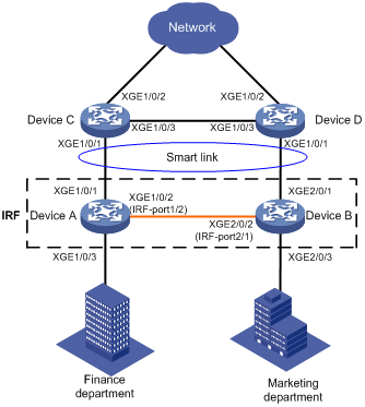
Network configuration
As shown in Figure 3, the Finance department in VLAN 10 and the Marketing department in VLAN 11 are connected to Device A and Device B, respectively. Device A and Device B form an IRF fabric and are connected to Device C and Device D.
Configure Smart Link to meet the following requirements:
· When the uplinks of Device A and Device B are available, traffic is forwarded through the link between Device A and Device C.
· When the link between Device A and Device C fails, the traffic switches to another link.
· When the link recovers, the traffic is switched back to the link.
|
Device |
Interface |
VLAN |
Device |
Interface |
Device |
|
Device A |
XGE1/0/1 |
10, 11 |
Device B |
XGE2/0/1 |
10, 11 |
|
XGE1/0/3 |
10 |
XGE2/0/3 |
11 |
||
|
Device C |
XGE1/0/1 |
10, 11 |
Device D |
XGE1/0/1 |
10, 11 |
|
XGE1/0/2 |
10, 11 |
XGE1/0/2 |
10, 11 |
Analysis
To implement dual uplink redundancy on Device A and Device B, configure a smart link group for the IRF fabric formed by Device A and Device B.
For the traffic to switch back to the recovered link, enable role preemption for the two smart link groups.
For the upstream device to refresh MAC address forwarding entries and ARP/ND entries when link switchover occurs in a smart link group, perform the following tasks:
· Enable flush message sending on Device A and Device B.
· Enable flush message receiving on Ten-GigabitEthernet 1/0/1 on Device C and Device D.
Applicable hardware and software versions
The following matrix shows the hardware and software versions to which this configuration example is applicable:
|
Hardware |
Software version |
|
S6520X-HI switch series S6520X-EI switch series |
Supported in Release 1110P01 |
|
S6520X-SI switch series S6520-SI switch series S5000-EI switch series MS4600 switch series |
Supported in Release 1110P01 |
Restrictions and guidelines
When you configure Smart Link in an IRF fabric, follow these restrictions and guidelines:
· Before you configure a port as a smart link group member, shut down the port to prevent loops. You can bring up the port only after completing the smart link group configuration.
· Before you configure a smart link member port or its directly connected port, disable the spanning tree feature and RRPP on the port.
· Make sure the receive control VLAN configured on the upstream device is the same as the transmit control VLAN configured on the smart link device.
· The control VLAN of a smart link group must also be one of its protected VLANs. Do not remove the control VLAN. Otherwise, flush messages cannot be sent correctly.
· For the restrictions and guidelines for configuring IRF, see H3C xxxx Virtual Technologies Configuration Guide.
Procedures
Setting up an IRF fabric
Configuring Device A
# Assign IRF member ID 1 to Device A.
<DeviceA> system-view
[DeviceA] irf member 1
# Bind Ten-GigabitEthernet 1/0/2 to IRF port 1/2 and save the configuration.
[DeviceA] interface ten-gigabitethernet 1/0/2
[DeviceA-Ten-GigabitEthernet1/0/2] shutdown
[DeviceA-Ten-GigabitEthernet1/0/2] quit
[DeviceA] irf-port 1/2
[DeviceA-irf-port1/2] port group interface ten-gigabitethernet 1/0/2
[DeviceA-irf-port1/2] quit
[DeviceA] interface ten-gigabitethernet 1/0/2
[DeviceA-Ten-GigabitEthernet1/0/2] undo shutdown
[DeviceA-Ten-GigabitEthernet1/0/2] quit
[DeviceA] save
# Activate the IRF port.
[DeviceA] irf-port-configuration active
Configuring Device B
# Assign IRF member ID 2 to Device B and reboot the device.
<DeviceB> system-view
[DeviceB] irf member 1 renumber 2
Warning: Renumbering the member ID may result in configuration change or loss. Continue? [Y/N]:y
[DeviceB] quit
<DeviceB> reboot
# After you connect the ports as shown in Figure 3, log in to the device again. Bind Ten-GigabitEthernet 1/0/2 to IRF port 2/1 and save the configuration.
<DeviceB> system-view
[DeviceB] interface ten-gigabitethernet 1/0/2
[DeviceB-Ten-GigabitEthernet1/0/2] shutdown
[DeviceB-Ten-GigabitEthernet1/0/2] quit
[DeviceB] irf-port 2/1
[DeviceB-irf-port2/1] port group interface ten-gigabitethernet 1/0/2
[DeviceB-irf-port2/1] quit
[DeviceB] interface ten-gigabitethernet 1/0/2
[DeviceB-Ten-GigabitEthernet1/0/2] undo shutdown
[DeviceB-Ten-GigabitEthernet1/0/2] quit
[DeviceB] save
# Activate the IRF port.
[DeviceB] irf-port-configuration active
Device A and Device B start a master election. When the master (Device A in this example) is elected, the other device reboots. An IRF fabric is formed after the reboot.
Configuring Smart Link
Configuring Device A
1. Create VLAN 10 and VLAN 11.
<DeviceA> system-view
[DeviceA] vlan 10 to 11
2. Configure Ten-GigabitEthernet 1/0/1:
# Shut down Ten-GigabitEthernet 1/0/1.
[DeviceA] interface ten-gigabitethernet 1/0/1
[DeviceA-Ten-GigabitEthernet1/0/1] shutdown
# Configure Ten-GigabitEthernet 1/0/1 as a trunk port.
[DeviceA-Ten-GigabitEthernet1/0/1] port link-type trunk
# Assign the port to VLAN 10 and VLAN 11.
[DeviceA-Ten-GigabitEthernet1/0/1] port trunk permit vlan 10 11
# Remove the port from VLAN 1.
[DeviceA-Ten-GigabitEthernet1/0/1] undo port trunk permit vlan 1
# Disable the spanning tree feature on the port.
[DeviceA-Ten-GigabitEthernet1/0/1] undo stp enable
[DeviceA-Ten-GigabitEthernet1/0/1] quit
3. Configure Ten-GigabitEthernet 2/0/1 in the same way Ten-GigabitEthernet 1/0/1 is configured.
[DeviceA] interface ten-gigabitethernet 2/0/1
[DeviceA-Ten-GigabitEthernet2/0/1] shutdown
[DeviceA-Ten-GigabitEthernet2/0/1] port link-type trunk
[DeviceA-Ten-GigabitEthernet2/0/1] port trunk permit vlan 10 11
[DeviceA-Ten-GigabitEthernet2/0/1] undo port trunk permit vlan 1
[DeviceA-Ten-GigabitEthernet2/0/1] undo stp enable
[DeviceA-Ten-GigabitEthernet2/0/1] quit
4. Configure Ten-GigabitEthernet 1/0/3:
# Configure Ten-GigabitEthernet 1/0/3 as an access port and assign the port to VLAN 10.
[DeviceA] interface ten-gigabitethernet 1/0/3
[DeviceA-Ten-GigabitEthernet1/0/3] port access vlan 10
# Bring up the port.
[DeviceA-Ten-GigabitEthernet1/0/3] undo shutdown
[DeviceA-Ten-GigabitEthernet1/0/3] quit
5. Configure Ten-GigabitEthernet 2/0/3:
# Configure Ten-GigabitEthernet 2/0/3 as an access port and assign the port to VLAN 11.
[DeviceA] interface ten-gigabitethernet 2/0/3
[DeviceA-Ten-GigabitEthernet2/0/3] port access vlan 11
# Bring up the port.
[DeviceA-Ten-GigabitEthernet2/0/3] undo shutdown
[DeviceA-Ten-GigabitEthernet2/0/3] quit
6. Configure VLAN-to-MSTI mappings and activate the MST region configuration::
# Enter MST region view.
[DeviceA] stp region-configuration
# Map VLAN 10 and VLAN 11 to MSTI 1.
[DeviceA-mst-region] instance 1 vlan 10 11
# Activate the MST region configuration
[DeviceA-mst-region] active region-configuration
[DeviceA-mst-region] quit
7. Configure smart link group 1:
# Create smart link group 1 and configure the VLANs mapped to MSTI 1, VLAN 10 and VLAN 11, as the protected VLANs.
[DeviceA] smart-link group 1
[DeviceA-smlk-group1] protected-vlan reference-instance 1
# Configure Ten-GigabitEthernet 1/0/1 as the primary port and Ten-GigabitEthernet 2/0/1 as the secondary port.
[DeviceA-smlk-group1] port ten-gigabitethernet 1/0/1 primary
[DeviceA-smlk-group1] port ten-gigabitethernet 2/0/1 secondary
# Enable flush message sending, and configure VLAN 10 as the transmit control VLAN.
[DeviceA-smlk-group1] flush enable control-vlan 10
# Enable role preemption and set the preemption delay to 10 seconds.
[DeviceA-smlk-group1] preemption mode role
[DeviceA-smlk-group1] preemption delay 10
[DeviceA-smlk-group1] quit
8. Bring up Ten-GigabitEthernet 1/0/1 and Ten-GigabitEthernet 2/0/1:
[DeviceA] interface ten-gigabitethernet 1/0/1
[DeviceA-Ten-GigabitEthernet1/0/1] undo shutdown
[DeviceA-Ten-GigabitEthernet1/0/1] quit
[DeviceA] interface ten-gigabitethernet 2/0/1
[DeviceA-Ten-GigabitEthernet2/0/1] undo shutdown
[DeviceA-Ten-GigabitEthernet2/0/1] quit
Configuring Device C
1. Create VLAN 10 and VLAN 11.
<DeviceC> system-view
[DeviceC] vlan 10 to 11
2. Configure Ten-GigabitEthernet 1/0/1:
# Configure Ten-GigabitEthernet 1/0/1 as a trunk port.
[DeviceC] interface ten-gigabitethernet 1/0/1
[DeviceC-Ten-GigabitEthernet1/0/1] port link-type trunk
# Assign the port to VLAN 10 and VLAN 11.
[DeviceC-Ten-GigabitEthernet1/0/1] port trunk permit vlan 10 11
# Remove the port from VLAN 1.
[DeviceC-Ten-GigabitEthernet1/0/1] undo port trunk permit vlan 1
# Disable the spanning tree feature on the port.
[DeviceC-Ten-GigabitEthernet1/0/1] undo stp enable
# Enable flush message receiving, and configure VLAN 10 and VLAN 11 as the receive control VLANs on the port.
[DeviceC-Ten-GigabitEthernet1/0/1] smart-link flush enable control-vlan 10 11
# Bring up the port.
[DeviceC-Ten-GigabitEthernet1/0/1] undo shutdown
[DeviceC-Ten-GigabitEthernet1/0/1] quit
3. Configure Ten-GigabitEthernet 1/0/2:
# Configure Ten-GigabitEthernet 1/0/2 as a trunk port.
[DeviceC] interface ten-gigabitethernet 1/0/2
[DeviceC-Ten-GigabitEthernet1/0/2] port link-type trunk
# Assign the port to VLAN 10 and VLAN 11.
[DeviceC-Ten-GigabitEthernet1/0/2] port trunk permit vlan 10 11
# Remove the port from VLAN 1.
[DeviceC-Ten-GigabitEthernet1/0/2] undo port trunk permit vlan 1
# Enable flush message receiving, and configure VLAN 10 and VLAN 11 as the receive control VLANs on the port.
[DeviceC-Ten-GigabitEthernet1/0/2] smart-link flush enable control-vlan 10 11
# Bring up the port.
[DeviceC-Ten-GigabitEthernet1/0/2] undo shutdown
[DeviceC-Ten-GigabitEthernet1/0/2] quit
Configuring Device D
1. Create VLAN 10 and VLAN 11.
<DeviceD> system-view
[DeviceD] vlan 10 to 11
2. Configure Ten-GigabitEthernet 1/0/1:
# Configure Ten-GigabitEthernet 1/0/1 as a trunk port.
[DeviceD] interface ten-gigabitethernet 1/0/1
[DeviceD-Ten-GigabitEthernet1/0/1] port link-type trunk
# Assign the port to VLAN 10 and VLAN 11.
[DeviceD-Ten-GigabitEthernet1/0/1] port trunk permit vlan 10 11
# Remove the port from VLAN 1.
[DeviceD-Ten-GigabitEthernet1/0/1] undo port trunk permit vlan 1
# Disable the spanning tree feature on the port.
[DeviceD-Ten-GigabitEthernet1/0/1] undo stp enable
# Enable flush message receiving and configure VLAN 10 and VLAN 11 as the receive control VLANs on the port.
[DeviceD-Ten-GigabitEthernet1/0/1] smart-link flush enable control-vlan 10 11
# Bring up the port.
[DeviceD-Ten-GigabitEthernet1/0/1] undo shutdown
[DeviceD-Ten-GigabitEthernet1/0/1] quit
3. Configure Ten-GigabitEthernet 1/0/2:
# Configure Ten-GigabitEthernet 1/0/2 as a trunk port.
[DeviceD] interface ten-gigabitethernet 1/0/2
[DeviceD-Ten-GigabitEthernet1/0/2] port link-type trunk
# Assign the port to VLAN 10 and VLAN 11.
[DeviceD-Ten-GigabitEthernet1/0/2] port trunk permit vlan 10 11
# Remove the port from VLAN 1.
[DeviceD-Ten-GigabitEthernet1/0/2] undo port trunk permit vlan 1
# Enable flush message receiving and configure VLAN 10 and VLAN 11 as the receive control VLANs on the port.
[DeviceD-Ten-GigabitEthernet1/0/2] smart-link flush enable control-vlan 10 11
# Bring up the port.
[DeviceD-Ten-GigabitEthernet1/0/2] undo shutdown
[DeviceD-Ten-GigabitEthernet1/0/2] quit
Verifying the configuration
1. Verify the IRF fabric configuration after you complete the configuration:
# (Centralized devices.) Display IRF fabric information on Device A.
<Sysname> display irf
MemberID Role Priority CPU-Mac Description
*+1 Master 1 0210-fc01-0001 -----
2 Standby 1 0210-fc02-0002 -----
--------------------------------------------------------
* indicates the device is the master.
+ indicates the device through which the user logs in.
The Bridge MAC of the IRF is: 00e0-fc00-1000
Auto upgrade : yes
Mac persistent : 6 min
Domain ID : 0
IRF mode : normal
The output shows that an IRF fabric has been established successfully.
# (Distributed devices.) Display IRF fabric information on Device A.
[DeviceA] display irf
MemberID Slot Role Priority CPU-Mac Description
*+1 1 Master 1 0210-fc01-0001 -----
2 0 Standby 1 0210-fc02-0002 -----
--------------------------------------------------
* indicates the device is the master.
+ indicates the device through which the user logs in.
The bridge MAC of the IRF is: 00e0-fc00-c518
Auto upgrade : yes
Mac persistent : 6 min
Domain ID : 0
Auto merge : yes
IRF mode : normal
The output shows that an IRF fabric has been established successfully.
2. Verify the smart link group configuration when Device A is operating correctly:
# Display information about all smart link groups on Device A.
[DeviceA] display smart-link group all
Smart link group 1 information:
Device ID : 00e0-fc00-c518
Preemption mode : Role
Preemption delay: 10(s)
Control VLAN : 10
Protected VLAN : Reference Instance 1
Member Role State Flush-count Last-flush-time
-----------------------------------------------------------------------------
XGE1/0/1 PRIMARY ACTIVE 3 18:16:44 2014/12/29
XGE2/0/1 SECONDARY STANDBY 0 NA
The output shows that in smart link group 1, the primary port Ten-GigabitEthernet 1/0/1 is active to transmit traffic from VLAN 10 and VLAN 11.
3. Verify the smart link group configuration when Ten-GigabitEthernet 1/0/1 on Device A is down.
# Display information about all smart link groups on Device A.
[DeviceA] display smart-link group all
Smart link group 1 information:
Device ID : 00e0-fc00-c518
Preemption mode : Role
Preemption delay: 10(s)
Control VLAN : 10
Protected VLAN : Reference Instance 1
Member Role State Flush-count Last-flush-time
-----------------------------------------------------------------------------
XGE1/0/1 PRIMARY DOWN 3 18:16:44 2014/12/29
XGE2/0/1 SECONDARY ACTIVE 1 18:22:37 2014/12/29
The output shows that in smart link group 1, the secondary port Ten-GigabitEthernet 2/0/1 is active to transmit traffic for VLAN 10 and VLAN 11.
# Display information about the received flush messages on Device C.
[DeviceC] display smart-link flush
Received flush packets : 1
Receiving interface of the last flush packet : Ten-GigabitEthernet1/0/3
Receiving time of the last flush packet : 18:22:39 2014/12/29
Device ID of the last flush packet : 00e0-fc00-c518
Control VLAN of the last flush packet : 10
# Display information about the received flush messages on Device D.
[DeviceD] display smart-link flush
Received flush packets : 1
Receiving interface of the last flush packet : Ten-GigabitEthernet1/0/1
Receiving time of the last flush packet : 18:22:38 2014/12/29
Device ID of the last flush packet : 00e0-fc00-c518
Control VLAN of the last flush packet : 10
Configuration files
· Device A:
#
sysname DeviceA
#
vlan 10 to 11
#
irf mac-address persistent always
irf auto-update enable
irf auto-merge enable
undo irf link-delay
irf member 1 priority 1
irf member 2 priority 1
irf mode normal
#
irf-port 1/2
port group 1 interface Ten-GigabitEthernet1/0/2
port group mdc 1 interface Ten-GigabitEthernet1/0/2
#
irf-port 2/1
port group 1 interface Ten-GigabitEthernet2/0/2
port group mdc 1 interface Ten-GigabitEthernet2/0/2
#
stp region-configuration
instance 1 vlan 10 to 11
active region-configuration
#
smart-link group 1
preemption mode role
preemption delay 10
flush enable control-vlan 10
protected-vlan reference-instance 1
#
interface Ten-GigabitEthernet1/0/1
port link-mode bridge
port link-type trunk
undo port trunk permit vlan 1
port trunk permit vlan 10 to 11
undo stp enable
port smart-link group 1 primary
#
interface Ten-GigabitEthernet1/0/3
port link-mode bridge
port access vlan 10
#
interface Ten-GigabitEthernet2/0/1
port link-mode bridge
port link-type trunk
undo port trunk permit vlan 1
port trunk permit vlan 10 to 11
undo stp enable
port smart-link group 1 secondary
#
interface Ten-GigabitEthernet2/0/3
port link-mode bridge
port access vlan 11
#
· Device C:
#
sysname DeviceC
#
vlan 10 to 11
#
interface Ten-GigabitEthernet1/0/1
port link-mode bridge
port link-type trunk
undo port trunk permit vlan 1
port trunk permit vlan 10 to 11
undo stp enable
smart-link flush enable control-vlan 10 to 11
#
interface Ten-GigabitEthernet1/0/2
port link-mode bridge
port link-type trunk
undo port trunk permit vlan 1
port trunk permit vlan 10 to 11
smart-link flush enable control-vlan 10 to 11
#
· Device D:
#
sysname DeviceD
#
vlan 10 to 11
#
interface Ten-GigabitEthernet1/0/1
port link-mode bridge
port link-type trunk
undo port trunk permit vlan 1
port trunk permit vlan 10 to 11
undo stp enable
smart-link flush enable control-vlan 10 to 11
#
interface Ten-GigabitEthernet1/0/2
port link-mode bridge
port link-type trunk
undo port trunk permit vlan 1
port trunk permit vlan 10 to 11
smart-link flush enable control-vlan 10 to 11
#