- Table of Contents
-
- H3C Fixed Port Campus Switches Configuration Examples-B70D029-6W100
- 01-Login Management Configuration Examples
- 02-RBAC Configuration Examples
- 03-Software Upgrade Examples
- 04-ISSU Configuration Examples
- 05-Software Patching Examples
- 06-Ethernet Link Aggregation Configuration Examples
- 07-Port Isolation Configuration Examples
- 08-Spanning Tree Configuration Examples
- 09-VLAN Configuration Examples
- 10-VLAN Tagging Configuration Examples
- 11-DHCP Snooping Configuration Examples
- 12-Cross-Subnet Dynamic IP Address Allocation Configuration Examples
- 13-IPv6 over IPv4 Tunneling with OSPFv3 Configuration Examples
- 14-IPv6 over IPv4 GRE Tunnel Configuration Examples
- 15-GRE with OSPF Configuration Examples
- 16-OSPF Configuration Examples
- 17-IS-IS Configuration Examples
- 18-BGP Configuration Examples
- 19-Policy-Based Routing Configuration Examples
- 20-OSPFv3 Configuration Examples
- 21-IPv6 IS-IS Configuration Examples
- 22-Routing Policy Configuration Examples
- 23-IGMP Snooping Configuration Examples
- 24-IGMP Configuration Examples
- 25-MLD Snooping Configuration Examples
- 26-IPv6 Multicast VLAN Configuration Examples
- 27-ACL Configuration Examples
- 28-Traffic Policing Configuration Examples
- 29-GTS and Rate Limiting Configuration Examples
- 30-Priority Mapping and Queue Scheduling Configuration Examples
- 31-Traffic Filtering Configuration Examples
- 32-AAA Configuration Examples
- 33-Port Security Configuration Examples
- 34-Portal Configuration Examples
- 35-SSH Configuration Examples
- 36-IP Source Guard Configuration Examples
- 37-Ethernet OAM Configuration Examples
- 38-CFD Configuration Examples
- 39-DLDP Configuration Examples
- 40-VRRP Configuration Examples
- 41-BFD Configuration Examples
- 42-NTP Configuration Examples
- 43-SNMP Configuration Examples
- 44-NQA Configuration Examples
- 45-Mirroring Configuration Examples
- 46-sFlow Configuration Examples
- 47-OpenFlow Configuration Examples
- 48-MAC Address Table Configuration Examples
- 49-Static Multicast MAC Address Entry Configuration Examples
- 50-IP Unnumbered Configuration Examples
- 51-MVRP Configuration Examples
- 52-MCE Configuration Examples
- 53-Attack Protection Configuration Examples
- 54-Smart Link Configuration Examples
- 55-RRPP Configuration Examples
- 56-BGP Route Selection Configuration Examples
- 57-IS-IS Route Summarization Configuration Examples
- 58-IRF Configuration Examples
- 59-VXLAN Configuration Examples
- Related Documents
-
| Title | Size | Download |
|---|---|---|
| 06-Ethernet Link Aggregation Configuration Examples | 191.46 KB |
Example: Configuring Layer 2 link aggregation
Applicable hardware and software versions
Example: Configuring Layer 2 link aggregation load sharing
Applicable hardware and software versions
Example: Configuring Layer 2 link aggregation in an IRF fabric
Applicable hardware and software versions
Example: Configuring Layer 3 link aggregation
Applicable hardware and software versions
Example: Configuring Layer 3 link aggregation load sharing
Applicable hardware and software versions
Introduction
This document provides Ethernet link aggregation configuration examples.
Prerequisites
The configuration examples in this document were created and verified in a lab environment, and all the devices were started with the factory default configuration. When you are working on a live network, make sure you understand the potential impact of every command on your network.
This document assumes that you have basic knowledge of Ethernet link aggregation.
Example: Configuring Layer 2 link aggregation
Network configuration
As shown in Figure 1, both Device A and Device B forward traffic from VLAN 10 and VLAN 20.
Configure link aggregation on Device A and Device B to meet the following requirements:
· VLAN 10 on Device A can communicate with VLAN 10 on Device B.
· VLAN 20 on Device A can communicate with VLAN 20 on Device B.
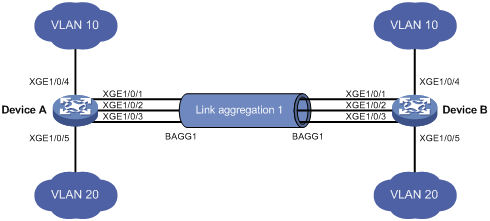
Analysis
To enable traffic from VLAN 10 and VLAN 20 to pass through Layer 2 aggregate interface Bridge-aggregation 1, perform the following tasks:
· Configure Layer 2 aggregate interface Bridge-aggregation 1 as a trunk port.
· Assign the aggregate interface to VLAN 10 and VLAN 20.
Applicable hardware and software versions
The following matrix shows the hardware and software versions to which this configuration example is applicable:
|
Hardware |
Software version |
|
S6520X-HI switch series S6520X-EI switch series |
Supported in Release 1110P01 |
|
S6520X-SI switch series S6520-SI switch series S5000-EI switch series MS4600 switch series |
Supported in Release 1110P01 |
Restrictions and guidelines
When you configure Layer 2 link aggregation, follow these restrictions and guidelines:
· When you assign a port to an aggregation group, the recommended configuration procedure is as follows:
a. Use the display this command in interface view to check the following attribute configurations of the port:
- Port isolation.
- QinQ.
- VLAN.
- VLAN mapping.
b. If any of the above configurations exist, use the undo forms of the corresponding commands to remove these configurations. This enables the port to use the default attribute configurations.
c. Assign the port to the aggregation group.
· In a static aggregation group, the Selected state of a port is not affected by whether the peer port is added to an aggregation group and is Selected. As a result, the Selected state of a port might be different from the Selected state of the peer port. When both ends support static aggregation and dynamic aggregation, use dynamic aggregation as a best practice.
· You cannot assign a port to a Layer 2 aggregation group when MAC authentication, port security mode, or 802.1X is configured or enabled on the port.
Procedures
1. Configure Device A:
# Create VLAN 10, and assign port Ten-GigabitEthernet 1/0/4 to VLAN 10.
<DeviceA> system-view
[DeviceA] vlan 10
[DeviceA-vlan10] port ten-gigabitethernet 1/0/4
[DeviceA-vlan10] quit
# Create VLAN 20, and assign port Ten-GigabitEthernet 1/0/5 to VLAN 20.
[DeviceA] vlan 20
[DeviceA-vlan20] port ten-gigabitethernet 1/0/5
[DeviceA-vlan20] quit
# Create Layer 2 aggregate interface Bridge-aggregation 1. Use one of the following methods as needed.
¡ Use the static aggregation mode to create Layer 2 aggregate interface Bridge-aggregation 1.
[DeviceA] interface bridge-aggregation 1
[DeviceA-Bridge-Aggregation1] quit
¡ Use the dynamic aggregation mode to create Layer 2 aggregate interface Bridge-aggregation 1.
[DeviceA] interface bridge-aggregation 1
[DeviceA-Bridge-Aggregation1] link-aggregation mode dynamic
[DeviceA-Bridge-Aggregation1] quit
# Assign ports Ten-GigabitEthernet 1/0/1 through Ten-GigabitEthernet 1/0/3 to aggregation group 1.
[DeviceA] interface range ten-gigabitethernet 1/0/1 to ten-gigabitethernet 1/0/3
[DeviceA-if-range] port link-aggregation group 1
[DeviceA-if-range] quit
# Configure Layer 2 aggregate interface Bridge-aggregation 1 as a trunk port.
[DeviceA] interface bridge-aggregation 1
[DeviceA-Bridge-Aggregation1] port link-type trunk
Configuring Ten-GigabitEthernet1/0/1 done.
Configuring Ten-GigabitEthernet1/0/2 done.
Configuring Ten-GigabitEthernet1/0/3 done.
# Assign the aggregate interface to VLANs 10 and 20.
[DeviceA-Bridge-Aggregation1] port trunk permit vlan 10 20
Configuring Ten-GigabitEthernet1/0/1 done.
Configuring Ten-GigabitEthernet1/0/2 done.
Configuring Ten-GigabitEthernet1/0/3 done.
[DeviceA-Bridge-Aggregation1] quit
2. Configure Device B in the same way Device A is configured. (Details not shown.)
Verifying the configuration
# Display detailed information about the link aggregation groups on Device A.
· Link aggregation configuration information when the static aggregation mode is used:
[DeviceA] display link-aggregation verbose
Loadsharing Type: Shar -- Loadsharing, NonS -- Non-Loadsharing
Port Status: S -- Selected, U -- Unselected, I -- Individual
Port: A -- Auto port, M -- Management port, R -- Reference port
Flags: A -- LACP_Activity, B -- LACP_Timeout, C -- Aggregation,
D -- Synchronization, E -- Collecting, F -- Distributing,
G -- Defaulted, H -- Expired
Aggregation Interface: Bridge-Aggregation1
Aggregation Mode: Static
Loadsharing Type: Shar
Management VLANs: None
Port Status Priority Oper-Key
XGE1/0/1(R) S 32768 1
XGE1/0/2 S 32768 1
XGE1/0/3 S 32768 1
The output shows that all member ports in the local aggregation group are in the Selected state. The Selected states of the local member ports are not affected by the Selected states of the peer member ports.
· Link aggregation configuration information when the dynamic aggregation mode is used:
[DeviceA] display link-aggregation verbose
Loadsharing Type: Shar -- Loadsharing, NonS -- Non-Loadsharing
Port Status: S -- Selected, U -- Unselected, I -- Individual
Port: A -- Auto port, M -- Management port, R -- Reference port
Flags: A -- LACP_Activity, B -- LACP_Timeout, C -- Aggregation,
D -- Synchronization, E -- Collecting, F -- Distributing,
G -- Defaulted, H -- Expired
Aggregation Interface: Bridge-Aggregation1
Aggregation Mode: Dynamic
Loadsharing Type: Shar
Management VLANs: None
System ID: 0x8000, 000f-e234-5678
Local:
Port Status Priority Index Oper-Key Flag
XGE1/0/1 S 32768 2 1 {ACDEF}
XGE1/0/2 S 32768 3 1 {ACDEF}
XGE1/0/3 S 32768 4 1 {ACDEF}
Remote:
Actor Priority Index Oper-Key SystemID Flag
XGE1/0/1(R) 32768 2 1 0x8000, a4e5-c316-0100 {ACDEF}
XGE1/0/2 32768 3 1 0x8000, a4e5-c316-0100 {ACDEF}
XGE1/0/3 32768 4 1 0x8000, a4e5-c316-0100 {ACDEF}
The output shows that the local member ports and the corresponding peer member ports are all Selected. In the dynamic link aggregation mode, each local member port and its peer member port have the same Selected state through exchanging LACPDUs. The user data traffic can be forwarded correctly.
Configuration files
· Device A:
#
vlan 10
#
interface Ten-GigabitEthernet1/0/4
port link-mode bridge
port access vlan 10
#
vlan 20
#
interface Ten-GigabitEthernet1/0/5
port link-mode bridge
port access vlan 20
¡ In the static aggregation mode:
#
interface Bridge-Aggregation1
port link-type trunk
port trunk permit vlan 10 20
¡ In the dynamic aggregation mode:
#
interface Bridge-Aggregation1
port link-type trunk
port trunk permit vlan 10 20
link-aggregation mode dynamic
#
interface Ten-GigabitEthernet1/0/1
port link-mode bridge
port link-type trunk
port trunk permit vlan 10 20
port link-aggregation group 1
#
interface Ten-GigabitEthernet1/0/2
port link-mode bridge
port link-type trunk
port trunk permit vlan 10 20
port link-aggregation group 1
#
interface Ten-GigabitEthernet1/0/3
port link-mode bridge
port link-type trunk
port trunk permit vlan 10 20
port link-aggregation group 1
#
· Device B:
The configuration file on Device B is the same as the configuration file on Device A.
Example: Configuring Layer 2 link aggregation load sharing
Network configuration
As shown in Figure 2, both Device A and Device B forward traffic from VLAN 10 and VLAN 20.
Configure link aggregation on Device A and Device B to meet the following requirements:
· VLAN 10 on Device A can communicate with VLAN 10 on Device B. VLAN 20 on Device A can communicate with VLAN 20 on Device B.
· The packets from VLAN 10 and VLAN 20 are load shared across the Selected ports of link aggregation groups 1 and 2 by source MAC addresses, respectively.
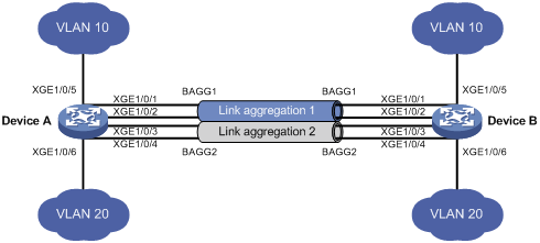
Analysis
To enable packets from VLAN 10 to pass through aggregate interface Bridge-aggregation 1, assign the aggregate interface to VLAN 10. To enable packets from VLAN 20 to pass through aggregate interface Bridge-aggregation 2, assign the aggregate interface to VLAN 20.
Applicable hardware and software versions
The following matrix shows the hardware and software versions to which this configuration example is applicable:
|
Hardware |
Software version |
|
S6520X-HI switch series S6520X-EI switch series |
Supported in Release 1110P01 |
|
S6520X-SI switch series S6520-SI switch series S5000-EI switch series MS4600 switch series |
Supported in Release 1110P01 |
Restrictions and guidelines
When you configure Layer 2 load sharing, follow these restrictions and guidelines:
· When you assign a port to an aggregation group, the recommended configuration procedure is as follows:
a. Use the display this command in interface view to check the following attribute configurations of the port:
- Port isolation.
- QinQ.
- VLAN.
- VLAN mapping.
b. If any of the above configurations exist, use the undo forms of the corresponding commands to remove these configurations. This enables the port to use the default attribute configurations.
c. Assign the port to the aggregation group.
· You cannot assign a port to a Layer 2 aggregation group when MAC authentication, port security mode, or 802.1X is configured or enabled on the port.
Procedures
1. Configure Device A:
# Create VLAN 10, and assign port Ten-GigabitEthernet 1/0/5 to VLAN 10.
<DeviceA> system-view
[DeviceA] vlan 10
[DeviceA-vlan10] port ten-gigabitethernet 1/0/5
[DeviceA-vlan10] quit
# Create VLAN 20, and assign port Ten-GigabitEthernet 1/0/6 to VLAN 20.
[DeviceA] vlan 20
[DeviceA-vlan20] port ten-gigabitethernet 1/0/6
[DeviceA-vlan20] quit
# Set the global link aggregation load sharing mode to source MAC address.
[DeviceA] link-aggregation global load-sharing mode source-mac
# Create Layer 2 aggregate interface Bridge-aggregation 1.
[DeviceA] interface bridge-aggregation 1
[DeviceA-Bridge-Aggregation1] quit
# Assign ports Ten-GigabitEthernet 1/0/1 and Ten-GigabitEthernet 1/0/2 to aggregation group 1.
[DeviceA] interface ten-gigabitethernet 1/0/1
[DeviceA-Ten-GigabitEthernet1/0/1] port link-aggregation group 1
[DeviceA-Ten-GigabitEthernet1/0/1] quit
[DeviceA] interface ten-gigabitethernet 1/0/2
[DeviceA-Ten-GigabitEthernet1/0/2] port link-aggregation group 1
[DeviceA-Ten-GigabitEthernet1/0/2] quit
# Assign Layer 2 aggregate interface Bridge-aggregation 1 to VLAN 10.
[DeviceA] interface bridge-aggregation 1
[DeviceA-Bridge-Aggregation1] port access vlan 10
Configuring Ten-GigabitEthernet1/0/1 done.
Configuring Ten-GigabitEthernet1/0/2 done.
[DeviceA-Bridge-Aggregation1] quit
# Create Layer 2 aggregate interface Bridge-aggregation 2.
[DeviceA] interface bridge-aggregation 2
[DeviceA-Bridge-Aggregation2] quit
# Assign ports Ten-GigabitEthernet 1/0/3 and Ten-GigabitEthernet 1/0/4 to aggregation group 2.
[DeviceA] interface ten-gigabitethernet 1/0/3
[DeviceA-Ten-GigabitEthernet1/0/3] port link-aggregation group 2
[DeviceA-Ten-GigabitEthernet1/0/3] quit
[DeviceA] interface ten-gigabitethernet 1/0/4
[DeviceA-Ten-GigabitEthernet1/0/4] port link-aggregation group 2
[DeviceA-Ten-GigabitEthernet1/0/4] quit
# Assign Layer 2 aggregate interface Bridge-aggregation 2 to VLAN 20.
[DeviceA] interface bridge-aggregation 2
[DeviceA-Bridge-Aggregation2] port access vlan 20
Configuring Ten-GigabitEthernet1/0/3 done.
Configuring Ten-GigabitEthernet1/0/4 done.
[DeviceA-Bridge-Aggregation2] quit
2. Configure Device B in the same way Device A is configured. (Details not shown.)
Verifying the configuration
# Display the information about Selected ports in link aggregation groups on Device A.
[DeviceA] display link-aggregation verbose
Loadsharing Type: Shar -- Loadsharing, NonS -- Non-Loadsharing
Port Status: S -- Selected, U -- Unselected , I -- Individual
Port: A -- Auto port, M -- Management port, R -- Reference port
Flags: A -- LACP_Activity, B -- LACP_Timeout, C -- Aggregation,
D -- Synchronization, E -- Collecting, F -- Distributing,
G -- Defaulted, H -- Expired
Aggregation Interface: Bridge-Aggregation1
Aggregation Mode: Static
Loadsharing Type: Shar
Management VLANs: None
Port Status Priority Oper-Key
XGE1/0/1(R) S 32768 1
XGE1/0/2 S 32768 1
Aggregation Interface: Bridge-Aggregation2
Aggregation Mode: Static
Loadsharing Type: Shar
Management VLANs: None
Port Status Priority Oper-Key
XGE1/0/3(R) S 32768 2
XGE1/0/4 S 32768 2
The output shows the following information:
· Link aggregation groups 1 and 2 are both Layer 2 static aggregation groups.
· Each aggregation group has two Selected ports for forwarding traffic.
# Display the global link aggregation load sharing mode.
[DeviceA]display link-aggregation load-sharing mode
Link-aggregation load-sharing mode:
source-mac address
The output shows that link aggregation groups 1 and 2 load share packets based on source MAC addresses.
Configuration files
· Device A:
#
link-aggregation global load-sharing mode source-mac
#
vlan 10
#
interface Ten-GigabitEthernet1/0/5
port link-mode bridge
port access vlan 10
#
vlan 20
#
interface Ten-GigabitEthernet1/0/6
port link-mode bridge
port access vlan 10
#
interface Bridge-Aggregation1
port access vlan 10
#
interface Ten-GigabitEthernet1/0/1
port link-mode bridge
port access vlan 10
port link-aggregation group 1
#
interface Ten-GigabitEthernet1/0/2
port link-mode bridge
port access vlan 10
port link-aggregation group 1
#
interface Bridge-Aggregation2
port access vlan 20
#
interface Ten-GigabitEthernet1/0/3
port link-mode bridge
port access vlan 20
port link-aggregation group 2
#
interface Ten-GigabitEthernet1/0/4
port link-mode bridge
port access vlan 20
port link-aggregation group 2
· Device B:
The configuration file on Device B is the same as the configuration file on Device A.
Example: Configuring Layer 2 link aggregation in an IRF fabric
Network configuration
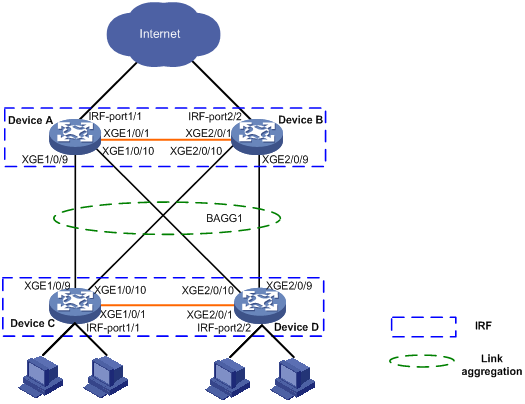
On the network as shown in Figure 3, perform the following tasks:
· Set up a two-chassis IRF fabric at the access layer and a two-chassis IRF fabric at the distribution layer of the enterprise network.
· Configure link aggregation to improve the reliability of the links between the access-layer and distribution-layer IRF fabrics and implement load sharing.
· Run LACP MAD on the two IRF fabrics to detect IRF split.
Applicable hardware and software versions
The following matrix shows the hardware and software versions to which this configuration example is applicable:
|
Hardware |
Software version |
|
S6520X-HI switch series S6520X-EI switch series |
Supported in Release 1110P01 |
|
S6520X-SI switch series S6520-SI switch series S5000-EI switch series MS4600 switch series |
Supported in Release 1110P01 |
Restrictions and guidelines
When you configure Layer 2 link aggregation in an IRF fabric, follow these restrictions and guidelines:
· IRF physical ports must be set to the bridge mode.
· When you bind physical ports to an IRF port, you must set all the physical ports to operate in either normal or enhanced mode.
· The physical ports of two connected IRF ports must operate in the same mode: normal or enhanced. For more information about the binding mode of the IRF physical ports, see IRF Configuration Guide.
· When you assign a port to an aggregation group, the recommended configuration procedure is as follows:
a. Use the display this command in interface view to check the following attribute configurations of the port:
- Port isolation.
- QinQ.
- VLAN.
- VLAN mapping.
b. If any of the above configurations exist, use the undo forms of the corresponding commands to remove these configurations. This enables the port to use the default attribute configurations.
c. Assign the port to the aggregation group.
· In a static aggregation group, the Selected state of a port is not affected by whether the peer port is added to an aggregation group and is Selected. As a result, the Selected state of a port might be different from the Selected state of the peer port. When both ends support static aggregation and dynamic aggregation, use dynamic aggregation as a practice.
· You cannot assign a port to a Layer 2 aggregation group when MAC authentication, port security mode, or 802.1X is configured or enabled on the port.
Procedures
1. Configure IRF on Device A:
# Shut down Ten-GigabitEthernet 1/0/1.
<DeviceA> system-view
[DeviceA] interface ten-gigabitethernet 1/0/1
[DeviceA-Ten-GigabitEthernet1/0/1] shutdown
[DeviceA-Ten-GigabitEthernet1/0/1] quit
# Bind Ten-GigabitEthernet 1/0/1 to IRF port 1/1.
[DeviceA] irf-port 1/1
[DeviceA-irf-port1/1] port group interface ten-gigabitethernet 1/0/1
You must perform the following tasks for a successful IRF setup:
Save the configuration after completing IRF configuration.
Execute the "irf-port-configuration active" command to activate the IRF ports.
[DeviceA-irf-port1/1] quit
# Bring up Ten-GigabitEthernet1/0/1, and save the configuration.
[DeviceA] interface ten-gigabitethernet 1/0/1
[DeviceA-Ten-GigabitEthernet1/0/1] undo shutdown
[DeviceA-Ten-GigabitEthernet1/0/1] quit
[DeviceA] save
# Activate the IRF port configuration.
[DeviceA] irf-port-configuration active
2. Configure IRF on Device B:
# Change the member ID of Device B to 2, and reboot the device to validate the change.
<DeviceB> system-view
[DeviceB] irf member 1 renumber 2
Renumbering the member ID may result in configuration change or loss. Continue? [Y/N]:y
[DeviceB] quit
<DeviceB> reboot
# Shut down Ten-Gigabitethernet 2/0/1.
<DeviceB> system-view
[DeviceB] interface ten-gigabitethernet 2/0/1
[DeviceB-Ten-GigabitEthernet2/0/1] shutdown
[DeviceB-Ten-GigabitEthernet2/0/1] quit
# Bind Ten-GigabitEthernet 2/0/1 to IRF port 2/2.
[DeviceB] irf-port 2/2
[DeviceB-irf-port2/2] port group interface ten-gigabitethernet 2/0/1
You must perform the following tasks for a successful IRF setup:
Save the configuration after completing IRF configuration.
Execute the "irf-port-configuration active" command to activate the IRF ports.
[DeviceB-irf-port2/2] quit
# Bring up Ten-GigabitEthernet 2/0/1, and save the configuration.
[DeviceB] interface ten-gigabitethernet 2/0/1
[DeviceB-Ten-GigabitEthernet2/0/1] undo shutdown
[DeviceB-Ten-GigabitEthernet2/0/1] quit
[DeviceB] save
# Activate the IRF port configuration.
[DeviceB] irf-port-configuration active
Device A and Device B perform master election, and the one that has lost the election reboots to form an IRF fabric with the master. In this example, Device B reboots.
# Use the display irf command to verify that Device A has become the Master device.
[DeviceA] display irf
MemberID Role Priority CPU-Mac Description
*+1 Master 1 00a0-fc00-5801 ---
2 Standby 1 00e0-fc58-1235 ---
--------------------------------------------------
* indicates the device is the master.
+ indicates the device through which the user logs in.
The bridge MAC of the IRF is: 00a0-fc00-5800
Auto upgrade : yes
Mac persistent : 6 min
Domain ID : 0
Auto merge : yes
3. Configure a Layer 2 aggregation group on Device A:
# Set the global link aggregation load sharing mode to source IP address.
[DeviceA] link-aggregation global load-sharing mode source-ip
# Create Layer 2 aggregate interface Bridge-Aggregation 1, and configure the link aggregation mode as dynamic.
[DeviceA] interface bridge-aggregation 1
[DeviceA-Bridge-Aggregation1] link-aggregation mode dynamic
[DeviceA-Bridge-Aggregation1] quit
# Assign ports Ten-GigabitEthernet 1/0/9, Ten-GigabitEthernet1/0/10, Ten-GigabitEthernet 2/0/9, and Ten-GigabitEthernet 2/0/10 to link aggregation group 1.
[DeviceA] interface range ten-gigabitethernet 1/0/9 to ten-gigabitethernet 1/0/10
ten-gigabitethernet 2/0/9 to ten-gigabitethernet 2/0/10
[DeviceA-if-range] port link-aggregation group 1
[DeviceA-if-range] quit
4. Configure LACP MAD on the IRF fabric:
# Set the domain ID of the IRF fabric to 1.
# Enable LACP MAD on Bridge-Aggregation 1.
[DeviceA] interface Bridge-Aggregation 1
[DeviceA-Bridge-Aggregation1] mad enable
You need to assign a domain ID (range: 0-4294967295)
[Current domain is: 1]:
The assigned domain ID is: 1
MAD LACP only enable on dynamic aggregation interface.
5. Configure IRF on Device C in the same way IRF is configured on Device A. (Details not shown.)
6. Configure IRF on Device D in the same way IRF is configured on Device B. (Details not shown.)
Device C and Device D perform master election, and the one that has lost the election reboots to form an IRF fabric with the master. In this example, Device C reboots.
7. Configure a Layer 2 dynamic aggregation group Bridge-Aggregation 1 on Device C in the same way Bridge-Aggregation 1 is configured on Device A. (Details not shown.)
8. Configure LACP MAD on the IRF fabric:
# Set the domain ID of the IRF fabric to 2.
<DeviceC> system-view
[DeviceC] irf domain 2
# Enable LACP MAD on Bridge-Aggregation 1.
[DeviceC] interface Bridge-Aggregation 1
[DeviceC-Bridge-Aggregation1] mad enable
You need to assign a domain ID (range: 0-4294967295)
[Current domain is: 2]:
The assigned domain ID is: 2
MAD LACP only enable on dynamic aggregation interface.
Verifying the configuration
# Display the information about the link aggregation groups on Device A.
[DeviceA] display link-aggregation verbose
Loadsharing Type: Shar -- Loadsharing, NonS -- Non-Loadsharing
Port Status: S -- Selected, U -- Unselected, I -- Individual
Port: A -- Auto port, M -- Management port, R -- Reference port
Flags: A -- LACP_Activity, B -- LACP_Timeout, C -- Aggregation,
D -- Synchronization, E -- Collecting, F -- Distributing,
G -- Defaulted, H -- Expired
Aggregate Interface: Bridge-Aggregation1
Aggregation Mode: Dynamic
Loadsharing Type: Shar
Management VLANs: None
System ID: 0x8000, 00a0-fc00-5800
Local:
Port Status Priority Index Oper-Key Flag
XGE1/0/9(R) S 32768 10 1 {ACG}
XGE1/0/10 S 32768 11 1 {ACG}
XGE2/0/9 S 32768 138 1 {ACG}
XGE2/0/10 S 32768 139 1 {ACG}
Remote:
Actor Priority Index Oper-Key SystemID Flag
XGE1/0/9 32768 0 0 0x8000, 0000-0000-0000 {EF}
XGE1/0/10 32768 0 0 0x8000, 0000-0000-0000 {EF}
XGE2/0/9 32768 0 0 0x8000, 0000-0000-0000 {EF}
XGE2/0/10 32768 0 0 0x8000, 0000-0000-0000 {EF}
The output shows that the local member ports and the corresponding peer member ports are all Selected. In the dynamic link aggregation mode, each local member port and its peer member port have the same Selected state through exchanging LACPDUs. The user data traffic can be forwarded correctly.
# Display the global link aggregation load sharing mode.
[DeviceA] display link-aggregation load-sharing mode
Link-aggregation load-sharing mode:
source-ip address
The output shows that Layer 2 aggregation group 1 load shares packets based on source IP addresses.
# Shut down physical IRF port Ten-GigabitEthernet 2/0/1 on Device B.
A log message appears on Device A.
[DeviceA]%Jul 9 16:52:41:734 2016 DeviceA STM/3/STM_LINK_DOWN: -MDC=1; IRF port 1 went down.
%Jul 9 16:52:41:800 2016 DeviceA IFNET/3/PHY_UPDOWN: -MDC=1; Physical state on the interface Ten-GigabitEthernet1/0/1 changed to down.
%Jul 9 16:52:41:854 2016 DeviceA IFNET/5/LINK_UPDOWN: -MDC=1; Line protocol state on the interface Ten-GigabitEthernet1/0/1 changed to down.
%Jul 9 16:52:41:867 2016 DeviceA DEV/3/BOARD_REMOVED: -MDC=1; Board was removed from slot 2, type is Simware.
The output shows that IRF split occurs on the distribution layer because Ten-GigabitEthernet 2/0/1 that is bound to IRF port 2/2 is physically down.
Configuration files
· Device A:
#
irf domain 1
irf mac-address persistent timer
irf auto-update enable
irf auto-merge enable
undo irf link-delay
irf member 1 priority 1
irf member 2 priority 1
#
irf-port 1/1
port group interface Ten-GigabitEthernet1/0/1
#
irf-port 2/2
port group interface Ten-GigabitEthernet2/0/1
#
link-aggregation global load-sharing mode source-ip
#
interface Bridge-Aggregation1
link-aggregation mode dynamic
#
interface Ten-GigabitEthernet1/0/9
port link-mode bridge
port link-aggregation group 1
#
interface Ten-GigabitEthernet1/0/10
port link-mode bridge
port link-aggregation group 1
#
interface Ten-GigabitEthernet2/0/9
port link-mode bridge
port link-aggregation group 1
#
interface Ten-GigabitEthernet2/0/10
port link-mode bridge
port link-aggregation group 1
#
· Device C:
The configuration file on Device C is similar as the configuration file on Device A.
Example: Configuring Layer 3 link aggregation
Network configuration
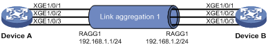
On the network as shown in Figure 4, perform the following tasks:
· Configure a Layer 3 dynamic aggregation group on both Device A and Device B.
· Configure IP addresses and subnet masks for the corresponding Layer 3 aggregate interfaces.
Applicable hardware and software versions
The following matrix shows the hardware and software versions to which this configuration example is applicable:
|
Hardware |
Software version |
|
S6520X-HI switch series S6520X-EI switch series |
Supported in Release 1110P01 |
|
S6520X-SI switch series S6520-SI switch series S5000-EI switch series MS4600 switch series |
Supported in Release 1110P01 |
Restrictions and guidelines
In a static aggregation group, the Selected state of a port is not affected by whether the peer port is added to an aggregation group and is Selected. As a result, the Selected state of a port might be different from the Selected state of the peer port. When both ends support static aggregation and dynamic aggregation, use dynamic aggregation as a practice.
Procedures
# Create Layer 3 aggregate interface Route-Aggregation 1. Use one of the following methods as needed.
¡ Use the static aggregation mode to create Layer 3 aggregate interface Route-Aggregation 1.
<DeviceA> system-view
[DeviceA] interface route-aggregation 1
¡ Use the dynamic aggregation mode to create Layer 3 aggregate interface Route-Aggregation 1.
[DeviceA] interface route-aggregation 1
[DeviceA-Route-Aggregation1] link-aggregation mode dynamic
# Configure an IP address and subnet mask for Layer 3 aggregate interface Route-Aggregation 1.
[DeviceA-Route-Aggregation1] ip address 192.168.1.1 24
[DeviceA-Route-Aggregation1] quit
# Assign ports Ten-GigabitEthernet 1/0/1 through Ten-GigabitEthernet 1/0/3 to aggregation group 1.
[DeviceA] interface range ten-gigabitethernet 1/0/1 to ten-gigabitethernet 1/0/3
[DeviceA-if-range] port link-mode route
[DeviceA-if-range] port link-aggregation group 1
[DeviceA-if-range] quit
Configure Device B in the same way Device A is configured. (Details not shown.)
Verifying the configuration
# Display detailed information about the link aggregation groups on Device A.
· Link aggregation configuration information when the static aggregation mode is used:
[DeviceA] display link-aggregation verbose
Loadsharing Type: Shar -- Loadsharing, NonS -- Non-Loadsharing
Port Status: S -- Selected, U -- Unselected, I -- Individual
Port: A -- Auto port, M -- Management port, R -- Reference port
Flags: A -- LACP_Activity, B -- LACP_Timeout, C -- Aggregation,
D -- Synchronization, E -- Collecting, F -- Distributing,
G -- Defaulted, H -- Expired
Aggregate Interface: Route-Aggregation1
Aggregation Mode: Static
Loadsharing Type: Shar
Management VLANs: None
Port Status Priority Oper-Key
XGE1/0/1 S 32768 1
XGE1/0/2 S 32768 1
XGE1/0/3 S 32768 1
The output shows that all member ports in the local aggregation group are in Selected state. The Selected states of the local member ports are not affected by the Selected states of the peer member ports.
· Link aggregation configuration information when the dynamic aggregation mode is used:
[DeviceA] display link-aggregation verbose
Loadsharing Type: Shar -- Loadsharing, NonS -- Non-Loadsharing
Port Status: S -- Selected, U -- Unselected, I -- Individual
Port: A -- Auto port, M -- Management port, R -- Reference port
Flags: A -- LACP_Activity, B -- LACP_Timeout, C -- Aggregation,
D -- Synchronization, E -- Collecting, F -- Distributing,
G -- Defaulted, H -- Expired
Aggregate Interface: Route-Aggregation1
Aggregation Mode: Dynamic
Loadsharing Type: Shar
Management VLANs: None
System ID: 0x8000, 000f-e267-6c6a
Local:
Port Status Priority Index Oper-Key Flag
XGE1/0/1(R) S 32768 2 1 {ACDEF}
XGE1/0/2 S 32768 3 1 {ACDEF}
XGE1/0/3 S 32768 4 1 {ACDEF}
Remote:
Actor Priority Index Oper-Key SystemID Flag
XGE1/0/1 32768 2 1 0x8000, 68fa-34f2-0200 {ACDEF}
XGE1/0/2 32768 3 1 0x8000, 68fa-34f2-0200 {ACDEF}
XGE1/0/3 32768 4 1 0x8000, 68fa-34f2-0200 {ACDEF}
The output shows that the local member ports and the corresponding peer member ports are all Selected. In the dynamic link aggregation mode, each local member port and its peer member port have the same Selected state through exchanging LACPDUs. The user data traffic can be forwarded correctly.
Configuration files
· Device A:
#
¡ In the static aggregation mode:
#
interface route-aggregation1
ip address 192.168.1.1 255.255.255.0
#
¡ In the dynamic aggregation mode:
#
interface route-aggregation1
ip address 192.168.1.1 255.255.255.0
link-aggregation mode dynamic
#
interface Ten-GigabitEthernet1/0/1
port link-mode route
port link-aggregation group 1
#
interface Ten-GigabitEthernet1/0/2
port link-mode route
port link-aggregation group 1
#
interface Ten-GigabitEthernet1/0/3
port link-mode route
port link-aggregation group 1
#
Device B:
The configuration file on Device B is similar as the configuration file on Device A.
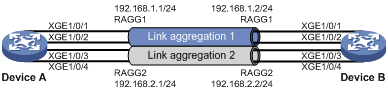
Example: Configuring Layer 3 link aggregation load sharing
Network configuration
On the network as shown in Figure 5, perform the following tasks:
· Configure Layer 3 static aggregation groups 1 and 2 on Device A and Device B.
· Configure IP addresses and subnet masks for the corresponding Layer 3 aggregate interfaces.
· Configure link aggregation groups 1 and 2 to load share packets based on source IP addresses.
Applicable hardware and software versions
The following matrix shows the hardware and software versions to which this configuration example is applicable:
|
Hardware |
Software version |
|
S6520X-HI switch series S6520X-EI switch series |
Supported in Release 1110P01 |
|
S6520X-SI switch series S6520-SI switch series S5000-EI switch series MS4600 switch series |
Supported in Release 1110P01 |
Procedures
# Set the global link aggregation load sharing mode to source IP address.
<DeviceA> system-view
[DeviceA] link-aggregation global load-sharing mode source-ip
# Create Layer 3 aggregate interface Route-Aggregation 1 and assign it an IP address.
[DeviceA] interface route-aggregation 1
[DeviceA-Route-Aggregation1] ip address 192.168.1.1 24
[DeviceA-Route-Aggregation1] quit
# Create Layer 3 aggregate interface Route-Aggregation 2 and assign it an IP address.
[DeviceA] interface route-aggregation 2
[DeviceA-Route-Aggregation2] ip address 192.168.2.1 24
[DeviceA-Route-Aggregation2] quit
# Assign Layer 3 Ethernet interfaces Ten-GigabitEthernet 1/0/1 and Ten-GigabitEthernet 1/0/2 to aggregation group 1.
[DeviceA] interface range ten-gigabitethernet 1/0/1 ten-gigabitethernet 1/0/2
[DeviceA-if-range] port link-aggregation group 1
[DeviceA-if-range] quit
# Assign Layer 3 Ethernet interfaces Ten-GigabitEthernet 1/0/3 and Ten-GigabitEthernet 1/0/4 to aggregation group 2.
[DeviceA] interface range ten-gigabitethernet 1/0/3 ten-gigabitethernet 1/0/4
[DeviceA-if-range] port link-aggregation group 2
[DeviceA-if-range] quit
Configure Device B in the same way Device A is configured. (Details not shown.)
Verifying the configuration
# Display detailed information about all aggregation groups on Device A.
[DeviceA] display link-aggregation verbose
Loadsharing Type: Shar -- Loadsharing, NonS -- Non-Loadsharing
Port Status: S -- Selected, U -- Unselected, I -- Individual
Port: A -- Auto port, M -- Management port, R -- Reference port
Flags: A -- LACP_Activity, B -- LACP_Timeout, C -- Aggregation,
D -- Synchronization, E -- Collecting, F -- Distributing,
G -- Defaulted, H -- Expired
Aggregate Interface: Route-Aggregation1
Aggregation Mode: Static
Loadsharing Type: Shar
Management VLANs: None
Port Status Priority Oper-Key
XGE1/0/1(R) S 32768 1
XGE1/0/2 S 32768 1
Aggregate Interface: Route-Aggregation2
Aggregation Mode: Static
Loadsharing Type: Shar
Management VLANs: None
Port Status Priority Oper-Key
XGE1/0/4 S 32768 2
The output shows that:
· Link aggregation groups 1 and 2 are both load-shared Layer 3 static aggregation groups.
· Each aggregation group contains two Selected ports.
# Display the global link aggregation load sharing mode on Device A.
[DeviceA] display link-aggregation load-sharing mode
Link-aggregation load-sharing mode:
source-ip address
The output shows that link aggregation groups 1 and 2 load share packets based on source IP addresses.
Configuration files
· Device A:
#
link-aggregation global load-sharing mode source-ip
#
interface Route-Aggregation1
ip address 192.168.1.1 255.255.255.0
#
interface Route-Aggregation2
ip address 192.168.2.1 255.255.255.0
#
interface Ten-GigabitEthernet1/0/1
port link-mode route
port link-aggregation group 1
#
interface Ten-GigabitEthernet1/0/2
port link-mode route
port link-aggregation group 1
#
interface Ten-GigabitEthernet1/0/3
port link-mode route
port link-aggregation group 2
#
interface Ten-GigabitEthernet1/0/4
port link-mode route
port link-aggregation group 2
#
· Device B:
The configuration file on Device B is similar as the configuration file on Device A.