- Table of Contents
- Related Documents
-
| Title | Size | Download |
|---|---|---|
| 02-WLAN Access Configuration | 239.95 KB |
WLAN access configuration task list
Configuring a WLAN service template
Creating a service template and specifying an SSID
Configuring the maximum number of associated clients
Configuring beacon measurement
Mapping a service template to a radio·
Shutting down all LEDs on the AP
Displaying and maintaining WLAN access
Configuring WLAN client isolation
Enabling WLAN client isolation
Specifying the uplink interface
WLAN access configuration examples
WLAN access configuration example
802.11ac configuration example
This chapter describes how to configure WLAN access.
WLAN access overview
A WLAN can provide the following services:
· WLAN client connectivity to conventional 802.3 LANs
· Secured WLAN access with different authentication and encryption methods
· Seamless roaming of WLAN clients in the mobility domain
Terminology
· Client—A handheld computer or laptop with a wireless NIC or a terminal that supports WiFi.
· Access point—An AP bridges frames between wireless and wired networks.
· Access controller—An AC can control and manage all APs in a WLAN. The AC communicates with an authentication server for WLAN client authentication.
· Fat AP—A fat AP controls and manages all associated wireless stations and bridges frames between wired and wireless networks.
· Service set identifier—A client scans all networks at first, and then selects a specific SSID to connect to a specific wireless network.
· Wireless medium—A medium used for transmitting frames between wireless clients. Radio frequency is used as the wireless medium in the WLAN system.
· Distribution system—A distribution system is used to forward frames to their destinations. It is the backbone to transmit frames between access points.
Client access
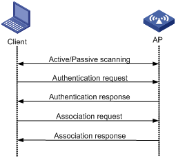
A wireless client access process involves three steps: active/passive scanning surrounding wireless services, authentication, and association, as shown in Figure 1.
Figure 1 Establishing a client access
Scanning
When a wireless client is operating, it usually uses both passive scanning and active scanning to get information about surrounding wireless networks.
1. Active scanning
When a wireless client operates, it periodically searches for (scans) surrounding wireless networks. During active scanning, the wireless client actively sends probe request frames and obtains network signals from received probe response frames. Active scanning falls into two modes according to whether a specified SSID is carried in a probe request.
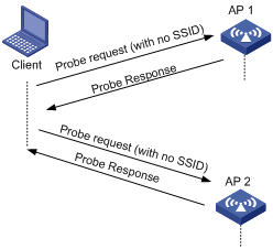
¡ A client sends a probe request (with the SSID null, or, the SSID IE length is 0): The client periodically sends a probe request frame on each of its supported channels to scan wireless networks. APs that receive the probe request send a probe response, which carries the available wireless network information. The client associates with the AP with the strongest signal. The active scanning mode enables a client to actively get acquainted with the available wireless services and to access the proper wireless network as needed. The active scanning process of a wireless client is as shown in Figure 2.
Figure 2 Active scanning (the SSID of the probe request is null or no SSID information is carried)
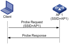
¡ A client sends a probe request (with a specified SSID): When the wireless client is configured to access a specific wireless network or has already successfully accessed a wireless network, the client periodically sends a probe request carrying the specified SSID of the configured or connected wireless network. When an AP that can provide the wireless service with the specified SSID receives the probe request, it sends a probe response. This active scanning mode enables a client to access a specified wireless network. The active scanning process is as shown in Figure 3.
Figure 3 Active scanning (the probe request carries the specified SSID AP 1)
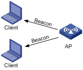
2. Passive scanning
Passive scanning is used by clients to discover surrounding wireless networks through listening to the beacon frames periodically sent by an AP. All APs providing wireless services periodically send beacons frames, so that wireless clients can periodically listen to beacon frames on the supported channels to get information about surrounding wireless networks and connect to an AP. Passive scanning is used by a client when it wants to save battery power. Typically, VoIP clients adopt the passive scanning mode. The passive scanning process is as shown in Figure 4.
Authentication
To secure wireless links, the wireless clients must be authenticated before accessing the AP, and only wireless clients passing the authentication can be associated with the AP. 802.11 links define two authentication mechanisms: open system authentication and shared key authentication.
For more information about the two authentication mechanisms, see "Configuring WLAN security."
Association
A client that wants to access a wireless network via an AP must be associated with that AP. Once the client chooses a compatible network with a specified SSID and passes the link authentication to an AP, it sends an association request frame to the AP. The AP detects the capability information carried in the association request frame, determines the capability supported by the wireless client, and sends an association response to the client to notify the client of the association result. Usually, a client can associate with only one AP at a time, and an association process is always initiated by the client.
WLAN access configuration task list
|
Task |
Description |
|
Required. |
|
|
Required. |
|
|
Optional. |
|
|
Required. |
Specifying a country code
A country code identifies the country in which you want to operate radios. It determines characteristics such as operating power level and total number of channels available for the transmission of frames. Set the valid country code or area code before configuring an AP.
Some ACs and fit APs have fixed country codes, whichever is used is determined as follows:
· An AC's fixed country code cannot be changed, and all managed fit APs whose country codes are not fixed must use the AC's fixed country code.
· A fit AP's fixed country code cannot be changed and the fit AP can only use the country code.
· If an AC and a managed fit AP use different fixed country codes, the fit AP uses its own fixed country code.
To specify the country code:
|
Step |
Command |
Remarks |
|
1. Enter system view. |
system-view |
N/A |
|
2. Specify the global country code. |
wlan country-code code |
By default, the country code is CN. |
Configuring a WLAN service template
Creating a service template and specifying an SSID
|
Step |
Command |
Remarks |
|
1. Enter system view. |
system-view |
N/A |
|
2. Create a WLAN service template and enter WLAN service template view. |
wlan service-template service-template-number { clear | crypto } |
You cannot change an existing service template to another type. |
|
3. Specify the service set identifier. |
ssid ssid-name |
N/A |
|
4. Disable the advertising of SSID in beacon frames. |
beacon ssid-hide |
Optional. By default, the SSID is advertised in beacon frames. |
Configuring the maximum number of associated clients
|
Step |
Command |
Remarks |
|
1. Enter system view. |
system-view |
N/A |
|
2. Create a WLAN service template and enter WLAN service template view. |
wlan service-template service-template-number { clear | crypto } |
You cannot change an existing service template to another type. |
|
3. Configure the maximum number of clients allowed to associate with a radio. |
client max-count max-number |
The default is 64. |
Configuring beacon measurement
Beacon measurement, defined by 802.11k, provides a mechanism for APs and clients to measure the available radio resources. When this function is enabled, an AP periodically sends beacon requests to clients. Clients respond with beacon reports to inform the AP of the beacon measurement information they have collected.
The beacon measurement function supports the following measure modes:
· Active—In this mode, the AP sends a beacon measurement request to a client. Upon receiving the request, the client broadcasts probe requests on all supported channels and sets a measurement duration timer. At the end of the measurement duration, the client compiles all received beacons and probe responses into a measurement report.
· Beacon-table—In this mode, the AP sends a beacon measurement request to a client. Upon receiving the request, the client measures beacons and returns a report to the AP. The report contains all beacon information stored on the client. The client does not perform any additional measurements.
· Passive—In this mode, the AP sends a beacon measurement request to a client. Upon receiving the request, the client sets a measurement duration timer. At the end of the measurement duration, the client compiles all received beacons and probe responses into a measurement report.
|
|
NOTE: This function is only applicable to clients that support the 802.11k protocol. |
To configure beacon measurement:
|
Step |
Command |
Remarks |
|
1. Enter system view. |
system-view |
N/A |
|
2. Create a WLAN service template and enter WLAN service template view. |
wlan service-template service-template-number { clear | crypto } |
You cannot change an existing service template to another type. |
|
3. Enable the beacon measurement function. |
beacon-measurement enable |
By default, this function is disabled. |
|
4. Set the beacon measurement mode. |
beacon-measurement type { active | beacon-table | passive } |
Optional. By default, the beacon-table bacon measurement mode is used. |
|
5. Set the interval at which the AP sends beacon request to clients. |
beacon-measurement interval interval |
Optional. By default, the interval is 60 seconds. |
|
6. Display beacon reports received from clients. |
display wlan client [ mac-address mac-address ] beacon-report [ | { begin | exclude | include } regular-expression ] |
N/A |
Enabling fast association
|
Step |
Command |
Remarks |
|
1. Enter system view. |
system-view |
N/A |
|
2. Create a WLAN service template and enter WLAN service template view. |
wlan service-template service-template-number { clear | crypto } |
You cannot change an existing service template to another type. |
|
3. Enable fast association. |
fast-association enable |
By default, fast association is disabled. When this function is enabled, the AP does not perform band navigation or load balancing calculation for clients bound to the SSID. |
Enabling a service template
|
Step |
Command |
Remarks |
|
1. Enter system view. |
system-view |
N/A |
|
2. Create a WLAN service template and enter WLAN service template view. |
wlan service-template service-template-number { clear | crypto } |
You cannot change an existing service template to another type. |
|
3. Enable the service template. |
service-template enable |
By default, the service template is disabled. |
Configuring WLAN parameters
|
Step |
Command |
Remarks |
|
1. Enter system view. |
system-view |
N/A |
|
2. Specify the maximum client idle time. |
wlan client idle-timeout interval |
Optional. The default is 3600 seconds. |
|
3. Specify the client keepalive interval. |
wlan client keep-alive interval |
Optional. By default, the client keep-alive function is disabled. |
|
4. Enable the AP to respond to probe requests with null SSID. |
broadcast-probe reply |
Optional. By default, the AP is enabled to respond to probe requests with null SSID. |
Configuring radio parameters
Configuring radio parameters
|
Step |
Command |
Remarks |
|
1. Enter system view. |
system-view |
N/A |
|
2. Enter radio interface view. |
interface wlan-radio interface-number |
N/A |
|
3. Configure a radio type. |
radio-type { dot11a | dot11an | dot11ac | dot11b | dot11g | dot11gn } |
Optional. |
|
4. Specify a working channel for the radio. |
channel { channel-number | auto } |
Optional. By default, auto mode is enabled. The working channel of a radio varies with country codes and radio types. An 802.11a, 802.11ac, or 802.11an radio interface supports the 36, 40, 44, 48, 52, 56, 60, 64, 149, 153, 157, 161, and 165 channels. An 802.11b, 802.11g, or 802.11gn radio interface supports channels 1 through 13. |
|
5. Specify the maximum radio power. |
max-power radio-power |
Optional. By default, the maximum radio power varies with country codes, channels, AP models, radio types, and antenna types. If 802.11n is adopted, the maximum radio power also depends on the bandwidth mode. |
|
6. Specify the type of preamble. |
preamble { long | short } |
Optional. By default, the short preamble is supported. |
|
7. Configure the antenna type. |
antenna type type |
Optional. The default antenna type is internal for WA4620i-ACN and Ext-Def for WA4620E-ACN. |
|
8. Enable Space Time Block Coding (STBC). |
stbc enable |
Optional. By default, STBC is enabled. Enabling STBC improves the SNR of the receiver and data transmission reliability. STBC takes effect only when the number of antennas on an AP is greater than the number of spatial streams corresponding to the rates used by the radio. For example, if the MCS is 8 and the corresponding spatial stream number is 2, STBC takes effect only when the AP has at least three antennas. |
|
9. Configure the maximum distance that the radio can cover. |
distance distance |
Optional. By default, the radio can cover 1 km (0.62 miles) at most. |
|
10. Set the interval for sending beacon frames. |
beacon-interval interval |
Optional. By default, the beacon interval is 100 TUs. |
|
11. Set the DTIM counter. |
dtim counter |
Optional. By default, the DTIM counter is 1. |
|
12. Specify the maximum length of packets that can be transmitted without fragmentation. |
fragment-threshold size |
Optional. By default, the fragment threshold is 2346 bytes and must be an even number. |
|
13. Set the maximum number of retransmission attempts for frames larger than the RTS threshold. |
long-retry threshold count |
Optional. By default, the long retry threshold is 4. |
|
14. Specify the maximum number of attempts to transmit a frame shorter than the RTS threshold. |
short-retry threshold count |
Optional. By default, the short retry threshold is 7. |
|
15. Specify the interval for the AP to hold received packets. |
max-rx-duration interval |
Optional. By default, the interval is 2000 milliseconds. |
|
16. Configure collision avoidance |
·
Specify the request to send (RTS) threshold
length. ·
Specify a collision avoidance mechanism. |
·
Optional. ·
Optional. |
|
17. Enable the energy saving function. |
green-energy-management enable |
Optional. By default, the energy saving function is disabled. |
|
18. Set the MIMO mode. |
mimo { 1x1 | 2x2 | 3x3 } |
Optional. By default, no MIMO mode is set for a radio. |
|
19. Enable Adaptive Noise Immunity (ANI). |
ani enable |
Optional. By default, ANI is enabled. |
Configuring 802.11n
As the next generation wireless LAN technology, 802.11n supports both 2.4-GHz and 5-GHz bands. It provides higher throughput by using the following methods:
· Increasing bandwidth: 802.11n can bond two adjacent 20-MHz channels together to form a 40-MHz channel. During data forwarding, the two 20-MHz channels can work separately with one acting as the primary channel and the other acting as the secondary channel or working together as a 40-MHz channel. This provides a simple way of doubling the data rate.
· Improving channel utilization through the following ways:
¡ 802.11n introduces the A-MPDU frame format. By using only one PHY header, each A-MPDU can accommodate multiple MPDUs which have their PHY headers removed. This reduces the overhead in transmission and the number of ACK frames to be used, and improves network throughput.
¡ Similar with MPDU aggregation, multiple MSDU can be aggregated into a single A-MSDU. This reduces the MAC header overhead and improves MAC layer forwarding efficiency.
¡ To improve physical layer performance, 802.11n introduces the short GI function, which shortens the GI interval of 800 ns in 802.11a/g to 400 ns. This can increase the data rate by 10 percent.
To configure 802.11n:
|
Step |
Command |
Remarks |
|
1. Enter system view. |
system-view |
N/A |
|
2. Enter WLAN-Radio interface view. |
interface wlan-radio interface-number |
N/A |
|
3. Specify the radio type. |
radio-type { dot11an | dot11gn } |
Optional. |
|
4. Specify the bandwidth mode for the radio. |
channel band-width { 20 | 40 } |
Optional. By default, the 802.11an radio operates in 40 MHz mode and the 802.11gn radio operates in 20 MHz mode. |
|
5. Enable access permission for 802.11n or 802.11ac clients . |
client dot11n-only |
Optional. By default, an 802.11an radio permits 802.11a, 802.11an, and 802.11ac client access. An 802.11gn radio permits both 802.11b/g and 802.11gn client access. This command permits 802.11n or 802.11ac clients in 5 GHz radio interface view, and permits 802.11n clients in 2.4 GHz radio interface view. |
|
6. Enable the short GI function. |
short-gi enable |
Optional. By default, the short GI function is enabled. |
|
7. Enable the A-MSDU function. |
a-msdu enable |
Optional. By default, the A-MSDU function is enabled. The device receives but does not send A-MSDUs. |
|
8. Enable the A-MPDU function. |
a-mpdu enable |
Optional. By default, the A-MPDU function is enabled. |
|
|
NOTE: For more information about MCS mandatory and supported 802.11n rates, see "Configuring WLAN RRM." |
Configuring 802.11ac
802.11ac provides higher throughput by using the following methods:
· Binding four 20-MHz channels to form an 80-MHz channel.
· Improving channel utilization in the same way as 802.11n.
To configure 802.11ac:
|
Step |
Command |
Remarks |
|
1. Enter system view. |
system-view |
N/A |
|
2. Enter WLAN-Radio interface view. |
interface wlan-radio interface-number |
N/A |
|
3. Set the bandwidth mode for the radio. |
channel band-width { 20 | 40 | 80 } |
Optional. By default, an 802.11ac radio operates in 80 MHz mode. |
|
4. Enable access permission for 802.11n and 802.11ac clients. |
client dot11n-only |
Optional. By default, an 802.11ac radio permits 802.11a, 802.11an, and 802.11ac clients to access. |
|
5. Enable access permission for 802.11ac clients. |
client dot11ac-only |
Optional. By default, an 802.11ac radio permits 802.11a, 802.11an, and 802.11ac clients to access. |
|
6. Enable the short GI function. |
short-gi enable |
Optional. By default, the short GI function is enabled. |
|
7. Enable the A-MSDU function. |
a-msdu enable |
Optional. By default, the A-MSDU function is enabled. The device receives but does not send A-MSDU packets. |
|
8. Enable the A-MPDU function. |
a-mpdu enable |
Optional. By default, the A-MPDU function is enabled. |
|
|
NOTE: For more information about mandatory NSS and supported NSS of 802.11ac, see "Configuring WLAN RRM." |
Mapping a service template to a radio
|
Step |
Command |
Remarks |
|
1. Enter system view. |
system-view |
N/A |
|
2. Enter radio interface view. |
interface wlan-radio interface-number |
N/A |
|
3. Configure a radio type. |
radio-type { dot11a | dot11an | dot11ac | dot11b | dot11g | dot11gn } |
Optional. The default radio type depends on the antenna model. |
|
4. Map a service template to the radio. |
service-template service-template-number [ vlan-id vlan-id ] |
Optional. You can map multiple service templates to the radio. |
Enabling a radio
|
Step |
Command |
Remarks |
|
1. Enter system view. |
system-view |
N/A |
|
2. Enter radio interface view. |
interface wlan-radio interface-number |
N/A |
|
3. Enable the radio. |
undo shutdown |
Optional. By default, the radio is disabled. |
Shutting down all LEDs on the AP
|
Step |
Command |
Remarks |
|
1. Enter system view. |
system-view |
N/A |
|
2. Shut down all LEDs on the AP. |
shut-all-led enable |
By default, all LEDs on the AP light based on AP status. |
Displaying and maintaining WLAN access
You can use the wlan link-test command to perform a Radio Frequency Ping (RFPing) operation to a client. The operation results show information about signal strength and RTT between the AP and the client.
|
Task |
Command |
Remarks |
|
Display WLAN client information. |
display wlan client { interface wlan-radio [ radio-number ] | mac-address mac-address | service-template service-template-number } [ verbose ] [ | { begin | exclude | include } regular-expression ] |
Available in any view. |
|
Display WLAN service template information. |
display wlan service-template [ service-template-number ] [ | { begin | exclude | include } regular-expression ] |
Available in any view. |
|
Display WLAN service template information or connection history information. |
display wlan statistics service-template service-template-number [ connect-history ] [ | { begin | exclude | include } regular-expression ] |
Available in any view. |
|
Display WLAN client statistics. |
display wlan statistics client { all | mac-address mac-address } [ | { begin | exclude | include } regular-expression ] |
Available in any view. |
|
Display beacon reports received from clients. |
display wlan client [ mac-address mac-address ] beacon-report [ | { begin | exclude | include } regular-expression ] |
Available in any view. |
|
Display information about bridge clients. |
display wlan client bridge [ interface wlan-radio [ radio-number ] ] [ verbose ] [ | { begin | exclude | include } regular-expression ] |
Available in any view. |
|
Cut off clients. |
reset wlan client { all | mac-address mac-address } |
Available in user view. |
|
Clear client statistics. |
reset wlan statistics client { all | mac-address mac-address } |
Available in user view. |
Configuring WLAN client isolation
User isolation enables an AP to isolate Layer-2 packets (unicast/broadcast) exchanged between wireless clients associated with it, disabling them from direct communication.
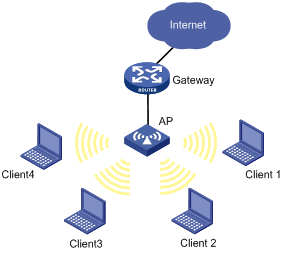
As shown in Figure 5, after the AP is enabled with user isolation, clients 1 through 4 cannot access each other directly or learn one another's MAC and IP addresses.
Enabling WLAN client isolation
|
Step |
Command |
Remarks |
|
1. Enter system view. |
system-view |
N/A |
|
2. Enable WLAN client isolation. |
wlan-client-isolation enable |
Optional. By default, this feature is enabled. |
Configuring uplink detection
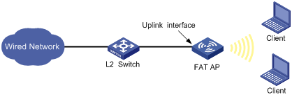
Specifying the uplink interface
The fat AP connects to a wired network through an uplink Ethernet interface, as shown in Figure 6. If the uplink Ethernet interface fails, the fat AP and associated clients cannot access the wired network. With uplink detection enabled, as long as its uplink interface fails, the AP stops providing WLAN services and the SSID of the AP is not available for the clients to access the WLAN until it recovers. In this way, WLAN clients can select other APs to access the network.
Figure 6 Uplink detection network diagram
To specify the uplink interface of the AP:
|
Step |
Command |
Remarks |
|
1. Enter system view. |
system-view |
N/A |
|
2. Specify the uplink interface. |
wlan uplink-interface interface-type interface-number |
Optional. By default, no interface is configured as an uplink interface. |
WLAN access configuration examples
WLAN access configuration example
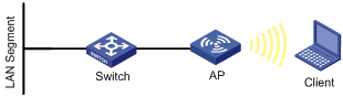
Network requirements
As shown in Figure 7, enable the client to access the internal network resources at any time. The AP provides a plain-text wireless access service with SSID service. 802.11g is adopted.
Configuration procedure
1. Configure the AP:
# Create a WLAN BSS interface.
<AP> system-view
[AP] interface wlan-bss 1
[AP-WLAN-BSS1] quit
# Configure a clear type WLAN service template, with no authentication.
[AP] wlan service-template 1 clear
[AP-wlan-st-1] ssid abc
[AP-wlan-st-1] authentication-method open-system
[AP-wlan-st-1] service-template enable
[AP-wlan-st-1] quit
# Bind WLAN-Radio 1/0/2 to service template 1 and WLAN-BSS 1.
[AP] interface wlan-radio 1/0/2
[AP-WLAN-Radio1/0/2] radio-type dot11g
[AP-WLAN-Radio1/0/2] channel 1
[AP-WLAN-Radio1/0/2] service-template 1 interface wlan-bss 1
2. Verify the configuration:
¡ The clients can associate with the AP and access the WLAN.
¡ You can use the display wlan client command to view the online clients.
802.11ac configuration example
Network requirements
As shown in Figure 8, deploy an 802.11ac network to provide high bandwidth access for multi-media applications. The AP provides a plain-text wireless service with SSID service.
Configuration procedure
1. Configure the AP:
# Create a WLAN BSS interface.
<AP> system-view
[AP] interface wlan-bss 1
[AP-WLAN-BSS1] quit
# Configure a clear type WLAN service template with no authentication.
[AP] wlan service-template 1 clear
[AP-wlan-st-1] ssid service
[AP-wlan-st-1] authentication-method open-system
[AP-wlan-st-1] service-template enable
[AP-wlan-st-1] quit
# Bind WLAN-Radio 1/0/1 to service template 1 and WLAN-BSS 1.
[AP] interface WLAN-Radio 1/0/1
[AP-WLAN-Radio1/0/1] radio-type dot11ac
[AP-WLAN-Radio1/0/1] service-template 1 interface WLAN-BSS 1
2. Verify the configuration:
¡ The clients can associate with the AP and access the WLAN.
¡ You can use the display wlan client verbose command to view the online clients. The command output displays the 802.11ac client information.