- Table of Contents
-
- H3C WX3800H Series Access Controllers Installation Guide-6W101
- 00-Preface
- 01-Preparing for installation
- 02-Installing the device
- 03-Troubleshooting
- 04-Hardware management and maintenance
- 05-Appendix A Chassis views and technical specifications
- 06-Appendix B LEDs
- 07-Appendix C Optional transceiver modules
- Related Documents
-
01-Preparing for installation
Download Book (548.42 KB)Preparing for installation
H3C WX3800H series access controllers include the following models:
· WX3820H
· WX3840H
Safety recommendations
To avoid any equipment damage or bodily injury, read the following safety recommendations before installation. Note that the recommendations do not cover every possible hazardous condition.
Safety symbols
When reading this document, note the following symbols:
![]() WARNING means an alert that calls attention to important information that if
not understood or followed can result in personal injury.
WARNING means an alert that calls attention to important information that if
not understood or followed can result in personal injury.
![]() CAUTION means an alert that calls attention to important information that if
not understood or followed can result in data loss, data corruption, or damage
to hardware or software.
CAUTION means an alert that calls attention to important information that if
not understood or followed can result in data loss, data corruption, or damage
to hardware or software.
General safety recommendations
· Make sure the installation site is flat, vibration-free, and away from electromagnetic interferences. Make sure ESD and anti-slip measures are in place.
· Do not place the device on an unstable case or desk. The device might be severely damaged in case of a fall.
· Keep the chassis and installation tools away from walk areas.
· Keep the chassis clean and dust-free.
· Do not place the device near water or in a damp environment. Prevent water or moisture from entering the device chassis.
· Ensure good ventilation of the equipment room and keep the air inlet and outlet vents of the device free of obstruction.
· Make sure the operating voltage is in the required range.
· Use a screwdriver to fasten screws.
· After you move the device from a location below 0°C (32°F) to the equipment room, follow these guidelines to prevent condensation:
¡ Wait a minimum of 30 minutes before unpacking the device.
¡ Wait a minimum of 2 hours before powering on the device.
Electrical safety
· Carefully examine your work area for possible hazards, such as moist floors, ungrounded power extension cables, or missing safety grounds.
· Locate the emergency power-off switch in the room before installation. Shut off the power immediately if an accident occurs.
· Remove all the external cables (including power cords) before moving the chassis.
· Do not work alone when you operate the device with the device powered on.
· Always verify that the power has been disconnected when you perform operations that require the device to be powered off.
Laser safety
|
|
WARNING! Disconnected optical fibers or connectors might emit invisible laser light. Do not stare into beams or view directly with optical instruments when the switch is operating. |
|
|
CAUTION: · Before you remove the optical fiber connector from a fiber port, execute the shutdown command in interface view to shut down the port. · Insert a dust cap into any open optical fiber connector and a dust plug into any open fiber port or transceiver module port to protect them from contamination and ESD damage. |
Examining the installation site
The device can only be used indoors. To ensure correct operation and a long lifespan for your device, the installation site must meet the requirements in this section.
Temperature and humidity
Maintain the temperature and humidity in the equipment room at acceptable levels.
· Lasting high relative humidity can cause poor insulation, electricity leakage, mechanical property change of materials, and metal corrosion.
· Lasting low relative humidity can cause washer contraction and ESD and bring problems including loose captive screws and circuit failure.
· High temperature can accelerate the aging of insulation materials and significantly lower the reliability and lifespan of the switch.
To ensure correct operation of the device, the equipment room must meet the temperature and humidity requirements listed in Table 1.
Table 1 Temperature/humidity requirements in the equipment room
|
Temperature |
Humidity |
|
0°C to 45°C (32°F to 113°F) |
5% RH to 95% RH, noncondensing |
Cleanliness
Dust buildup on the chassis can result in electrostatic adsorption, which causes poor contact of metal components and contact points, especially when indoor relative humidity is low. In the worst case, electrostatic adsorption can cause communication failure. To ensure correct operation, the equipment room must meet the dust concentration requirements listed in Table 2.
Table 2 Dust concentration limit in the equipment room
|
Substance |
Concentration limit (particles/m3) |
|
Dust particles |
≤ 3 x 10⁴ (No visible dust on desk in three days) |
|
NOTE: Dust particle diameter ≥ 5 µm |
|
To eliminate corrosion and premature aging of components, the equipment room must also meet limits on salts, acids, and sulfides, as shown in Table 3.
Table 3 Harmful gas limits in an equipment room
|
Gas |
Max. (mg/m3) |
|
SO2 |
0.2 |
|
H2S |
0.006 |
|
NH3 |
0.05 |
|
Cl2 |
0.01 |
|
NO2 |
0.04 |
Cooling
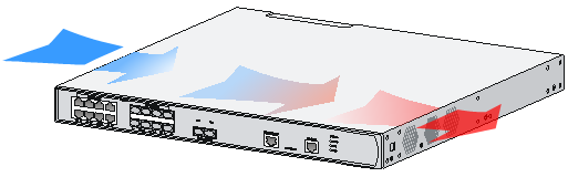
The device uses left-to-right airflow. For adequate heat dissipation, plan the installation site for the device based on its airflow direction and make sure the following requirements are met:
· A minimum clearance of 100 mm (3.94 in) is reserved around the air vents.
· The rack or workbench where the device is to be installed has a good ventilation system.
Figure 1 Airflow through the chassis (WX3840H)
ESD prevention
ESD prevention guidelines
To prevent electrostatic discharge (ESD), follow these guidelines:
· Ground the device and rack or workbench reliably.
· Take dust-proof measures for the equipment room. For more information, see "Cleanliness."
· Maintain the humidity and temperature at acceptable levels. For more information, see "Temperature and humidity."
· Before working with the device, wear an ESD wrist strap or gloves and ESD garment, and remove conductive objects such as jewelry or watch. Make sure the wrist strap makes good skin contact and is reliably grounded.
· Always remember to wear an ESD wrist strap when working with a transceiver module.
Attaching an ESD wrist strap
No ESD wrist strap is provided with the device. Prepare one yourself.
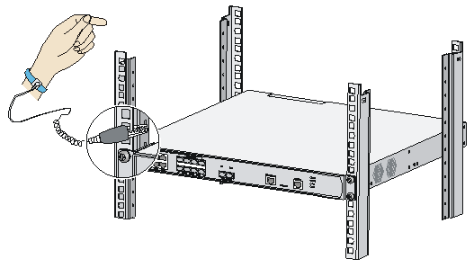
To attach an ESD wrist strap:
1. Wear the wrist strap on your wrist.
2. Lock the wrist strap tight around your wrist to maintain good contact with the skin.
3. Secure the wrist strap lock and the alligator clip lock together.
4. Attach the alligator clip to the rack.
5. Make sure the rack is reliably grounded.
Figure 2 Attaching an ESD wrist strap (WX3840H)
EMI
All electromagnetic interference (EMI) sources, from outside or inside of the device and application system, adversely affect the device in the following ways:
· A conduction pattern of capacitance coupling.
· Inductance coupling.
· Electromagnetic wave radiation.
· Common impedance (including the grounding system) coupling.
To prevent EMI, perform the following tasks:
· If AC power is used, use a single-phase three-wire power receptacle with protection earth (PE) to filter interference from the power grid.
· Keep the device far away from radio transmitting stations, radar stations, and high-frequency devices.
· Use electromagnetic shielding, for example, shielded interface cables, when necessary.
· To prevent signal ports from getting damaged by overvoltage or overcurrent caused by lightning strikes, route interface cables only indoors. If you must route interface cables outdoors, install network port lightning protectors.
Lightning protection
To better protect the device from lightning, follow these guidelines:
· Make sure the grounding cable of the chassis is reliably grounded.
· Make sure the grounding terminal of the AC power receptacle is reliably grounded.
· Install a lightning protector at the input end of the power module to enhance the lightning protection capability of the power supply.
Installation accessories
The installation accessories vary by device model. Table 4 describes the installation accessories available for the access controllers.
Table 4 Installation accessories for the access controllers
|
Accessory |
WX3820H |
WX3840H |
|
|
Cage nut |
|
4, user supplied |
4, user supplied |
|
M6 rack screw |
|
4, user supplied |
4, user supplied |
|
M3 mounting bracket screw |
|
8 |
8 |
|
Rubber feet |
|
1 set |
1 set |
|
Grounding cable |
|
1 |
1 |
|
Console cable |
|
1 |
1 |
|
Front mounting bracket |
|
2 |
2 |


Installation tools
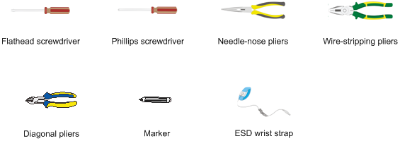
No installation tools are provided with the device. Prepare installation tools as required.
Figure 3 Installation tools
Pre-installation checklist
Table 5 Pre-installation checklist
|
Item |
Requirements |
Result |
|
|
Installation site |
Ventilation |
· There is a minimum clearance of 100 mm (3.94 in)) around the inlet and outlet vents for heat dissipation of the device chassis. · A good ventilation system is available at the installation site. |
|
|
Temperature |
0°C to 45°C (32°F to 113°F) |
|
|
|
Humidity |
5% RH to 95% RH (noncondensing) |
|
|
|
Cleanliness |
· Dust concentration ≤ 3 × 10⁴ particles/m3 · No dust on desk within three days |
|
|
|
ESD prevention |
· The equipment and rack or workbench are reliably grounded. · The equipment room is dust-proof. · The humidity and temperature are at acceptable levels. · An ESD wrist strap is available. |
|
|
|
EMI prevention |
· Effective measures are taken for filtering interference from the power grid. · The protection ground of the device is away from the grounding facility of power equipment or lightning protection grounding facility. · The device is far away from radio transmitting stations, radar stations, and high-frequency devices. · Electromagnetic shielding, for example, shielded interface cables, is used as required. |
|
|
|
Lightning protection |
· The device is reliably grounded. · The AC power source is reliably grounded. · (Optional.) Network port lightning protectors are available. · (Optional.) A surge protected power strip is available. |
|
|
|
Electricity safety |
· A UPS is available. · The power-off switch in the equipment room is identified and accessible so that the power can be immediately shut off when an accident occurs. |
|
|
|
Rack-mounting requirements |
· The rack has a good ventilation system. · The rack is sturdy enough to support the weight of the device and installation accessories. · The size of the rack is appropriate for the device. · The front and rear of the rack are a minimum of 0.8 m (2.62 ft) away from walls or other devices. |
|
|
|
Safety precautions |
· The device is far away from any moist area and heat source. · You have located the emergency power switch in the equipment room. |
|
|
|
Accessories |
Accessories provided with the device are available. |
|
|
|
Reference |
· Documents shipped with the device are available. · Online documents are available. |
|
|
