- Table of Contents
-
- 04-Layer 3 Configuration Guide
- 00-Preface
- 01-ARP Configuration
- 02-IP Addressing Configuration
- 03-DHCP Configuration
- 04-DHCPv6 Configuration
- 05-DNS Configuration
- 06-IPv6 DNS Configuration
- 07-NAT Configuration
- 08-Adjacency Table Configuration
- 09-Flow Classification Configuration
- 10-IPv6 Basics Configuration
- 11-IP Performance Optimization Configuration
- 12-IP Routing Basics
- 13-Static Routing Configuration
- 14-IPv6 Static Routing Configuration
- 15-GRE Configuration
- 16-RIP Configuration
- 17-RIPng Configuration
- 18-Policy-Based Routing Configuration
- Related Documents
-
| Title | Size | Download |
|---|---|---|
| 15-GRE Configuration | 252.79 KB |
GRE encapsulation and de-encapsulation
Configuring a GRE over IPv4 tunnel
Configuring a GRE over IPv6 tunnel
Displaying and maintaining GRE
GRE over IPv4 tunnel configuration example
GRE over IPv6 tunnel configuration example
Configuring GRE
Support for this feature depends on the device model. For more information, see About the H3C Access Controllers Configuration Guides.
Overview
GRE encapsulation format
Figure 1 GRE encapsulation format
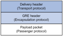
As shown in Figure 1, a GRE-tunneled packet comprises the following parts:
· Payload packet—Original packet. The protocol type of the payload packet is called the passenger protocol.
· GRE header—After GRE receives a payload packet, it adds a GRE header to the payload packet to change the payload packet to a GRE packet. GRE is called the encapsulation protocol.
· Delivery header—Transport protocol used to transfer the GRE packet. The system adds a transport protocol header to the GRE packet to deliver it to the tunnel end.
For example, to transfer an IPv6 packet over an IPv4 network through a GRE tunnel, the system encapsulates the IPv6 packet in the format shown in Figure 2. The passenger protocol is IPv6, the encapsulation protocol is GRE, and the transport protocol is IPv4.
Figure 2 Format of a GRE-encapsulated packet

Depending on the transport protocol, GRE tunnels fall into the following types:
· GRE over IPv4—The transport protocol is IPv4, and the passenger protocol is any network layer protocol.
· GRE over IPv6—The transport protocol is IPv6, and the passenger protocol is any network layer protocol.
GRE encapsulation and de-encapsulation
The following sections use Figure 3 to describe how an X protocol packet traverses an IP network through a GRE tunnel.
Figure 3 X protocol networks interconnected through a GRE tunnel

Encapsulation process
1. After receiving an X protocol packet from the interface connected to Group 1, Device A submits it to the X protocol for processing.
2. The X protocol checks the destination address field in the packet header to determine how to route the packet.
3. If the packet must be tunneled to reach its destination, Device A sends the packet to the GRE tunnel interface.
4. Upon receiving the packet, the tunnel interface encapsulates the packet with GRE and then with IP.
5. Device A looks up the routing table according to the destination address in the IP header and forwards the IP packet.
De-encapsulation process
De-encapsulation is the reverse of the encapsulation process:
1. Upon receiving an IP packet from the tunnel interface, Device B checks the destination address.
2. If the destination is itself and the protocol number in the IP header is 47 (the protocol number for GRE), Device B removes the IP header of the packet and submits the resulting packet to GRE for processing (such as checking the GRE key, checksum, and sequence number in the packet).
3. After GRE finishes the processing, Device B removes the GRE header and submits the payload to the X protocol for forwarding.
|
|
NOTE: GRE encapsulation and de-encapsulation can decrease the forwarding efficiency of tunnel-end devices. |
GRE security features
GRE supports the following security features to ensure GRE tunnel security:
· GRE key—Ensures packet validity. The sender adds a GRE key into a packet. The receiver compares the GRE key with its own GRE key. If the two keys are the same, the receiver accepts the packet. Otherwise, it drops the packet.
· GRE checksum—Ensures packet integrity. The sender calculates a checksum for the GRE header and payload and sends the packet containing the checksum to the tunnel peer. The receiver calculates a checksum for the received packet and compares it with that carried in the packet. If the checksums are the same, the receiver considers the packet intact and continues to process the packet. Otherwise, the receiver discards the packet.
GRE application scenarios
The following shows typical GRE application scenarios:
Connecting private networks running different protocols over a single backbone
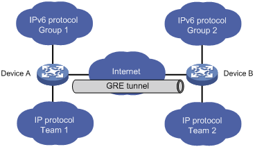
As shown in Figure 4, Group 1 and Group 2 are IPv6 networks, and Team 1 and Team 2 are IPv4 networks. Through the GRE tunnel between Device A and Device B, Group 1 can communicate with Group 2 and Team 1 can communicate with Team 2, without affecting each other.
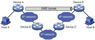
Enlarging network scope
In an IP network, the maximum TTL value of a packet is 255. If two devices have more than 255 hops in between, they cannot communicate with each other. By using a GRE tunnel, you can hide some hops to enlarge the network scope. As shown in Figure 5, only the tunnel-end devices (Device A and Device D) of the GRE tunnel are counted in hop count calculation. Therefore, there are only three hops between Host A and Host B.
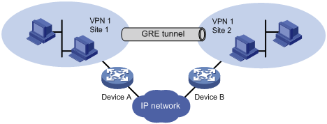
Constructing VPN
As shown in Figure 6, Site 1 and Site 2 both belong to VPN 1 and are located in different cities. Using a GRE tunnel can connect the two VPN sites across the WAN.
Operating with IPsec
As shown in Figure 7, GRE can be encapsulated into IPsec to improve transmission security for routing protocol packets, voice data, and video data.
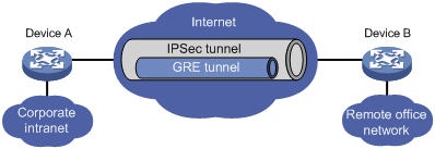
For more information about IPsec, see Security Configuration Guide.
Protocols and standards
· RFC 1701, Generic Routing Encapsulation (GRE)
· RFC 1702, Generic Routing Encapsulation over IPv4 networks
· RFC 2784, Generic Routing Encapsulation (GRE)
Configuring a GRE over IPv4 tunnel
Configuration guidelines
· The source address and destination address of a tunnel uniquely identify a path. You must configure the tunnel source address and destination address at both ends of a tunnel and the tunnel source or destination address at one end must be the tunnel destination or source address at the other end.
· Tunnel interfaces using the same encapsulation protocol must have different source addresses and destination addresses.
· If you configure a source interface for a tunnel interface, the tunnel interface takes the primary IP address of the source interface as its source address.
· You can enable or disable GRE checksum at both ends of a tunnel.
¡ If checksum is enabled at the local end but not at the remote end, the local end calculates the checksum of a packet to be sent but does not check the checksum of a received packet.
¡ If checksum is enabled at the remote end but not at the local end, the local end checks the checksum of a received packet but does not calculate the checksum of a packet to be sent.
· You can use the following methods to configure a route to a destination over the GRE tunnel:
¡ Configure a static route, using the destination address of the original packet as the destination address of the route and the address of the peer tunnel interface as the next hop.
¡ Enable a dynamic routing protocol on both the tunnel interface and the interface connecting the private network, so the dynamic routing protocol can establish a routing entry with the tunnel interface as the outgoing interface.
· The IP address of the tunnel interface and the tunnel destination address configured on the tunnel interface must be in different subnets.
Configuration prerequisites
Configure an IP address for the interface (such as a VLAN interface or a Loopback interface) to be used as the source interface of the tunnel interface.
Configuration procedure
To configure a GRE over IPv4 tunnel:
|
Step |
Command |
Remarks |
|
1. Enter system view. |
system-view |
N/A |
|
2. Create a tunnel interface and enter tunnel interface view. |
interface tunnel interface-number |
By default, a device has no tunnel interface. |
|
3. Configure an IPv4 address for the tunnel interface. |
ip address ip-address { mask | mask-length } |
By default, a tunnel interface has no IPv4 address. |
|
4. Set the tunnel mode to GRE over IPv4. |
tunnel-protocol gre |
Optional. The default tunnel mode is GRE over IPv4. You must configure the same tunnel mode on both ends of a tunnel. Otherwise, packet delivery will fail. |
|
5. Configure the source address or interface for the tunnel interface. |
source { ip-address | interface-type interface-number } |
By default, no source address or interface is configured for a tunnel interface. |
|
6. Configure the destination address for the tunnel interface. |
destination ip-address |
By default, no destination address is configured for a tunnel interface. |
|
7. Enable GRE keepalive and set the interval and the maximum number of transmission attempts. |
keepalive [ seconds [ times ] ] |
Optional. Disabled by default. |
|
8. Enable GRE packet checksum. |
gre checksum |
Optional. Disabled by default. |
|
9. Configure the key for the GRE tunnel interface. |
gre key key-number |
Optional. By default, no key is configured for a GRE tunnel interface. The two ends of a tunnel must have the same key or have no key at the same time. |
|
10. Specify a value for the Recursion Control field in the GRE header. |
gre recursion recursion-value |
Optional. By default, the value of the Recursion Control field in the GRE header is 0, which means not to limit the number of encapsulations. |
|
11. Configure a route for packet forwarding through the tunnel. |
See the configuration guides for static routing and dynamic routing protocols. |
Each end of the tunnel must have a route (static or dynamic) through the tunnel to the other end. |
|
12. Return to system view. |
quit |
N/A |
|
13. Configure the device to discard the IPv4-compatible IPv6 packets. |
tunnel discard ipv4-compatible-packet |
Optional. By default, the device does not discard the IPv4-compatible IPv6 packets. |
Configuring a GRE over IPv6 tunnel
Follow these guidelines when you configure a GRE over IPv6 tunnel:
· Deleting a tunnel interface also deletes the functions configured on this tunnel interface.
· The source address and destination address of a tunnel uniquely identify a path. You must configure the tunnel source address and destination address at both ends of a tunnel and the tunnel source or destination address at one end must be the tunnel destination or source address at the other end.
· Tunnel interfaces using the same encapsulation protocol must have different source addresses and destination addresses.
· If you configure a source interface for a tunnel interface, the tunnel interface takes the primary IP address of the source interface as its source address.
· You can enable or disable GRE checksum at both ends of a tunnel.
¡ If checksum is enabled at the local end but not at the remote end, the local end calculates the checksum of a packet to be sent but does not check the checksum of a received packet.
¡ If checksum is enabled at the remote end but not at the local end, the local end checks the checksum of a received packet but does not calculate the checksum of a packet to be sent.
· You can use the following methods to configure a route to a destination over the GRE tunnel:
¡ Configure a static route, using the destination address of the original packet as the destination address of the route and the address of the peer tunnel interface as the next hop.
¡ Enable a dynamic routing protocol on both the tunnel interface and the interface connecting the private network, so the dynamic routing protocol can establish a routing entry with the tunnel interface as the outgoing interface.
· The IPv6 address of the tunnel interface and the tunnel destination address configured on the tunnel interface must be in different subnets.
Configuration prerequisites
Configure an IPv6 address for the interface (such as a VLAN interface or a Loopback interface) to be used as the source interface of the tunnel interface.
Configuration procedure
To configure a GRE over IPv6 tunnel:
|
Step |
Command |
Remarks |
|
1. Enter system view. |
system-view |
N/A |
|
2. Enable the IPv6 packet forwarding function. |
ipv6 |
Disabled by default. |
|
3. Create a tunnel interface and enter tunnel interface view. |
interface tunnel interface-number |
By default, there is no tunnel interface on a device. |
|
4. Configure an IPv4 address for the tunnel interface. |
ip address ip-address { mask | mask-length } |
By default, no IPv4 address is configured for a tunnel interface. |
|
5. Set the tunnel mode to GRE over IPv6. |
tunnel-protocol gre ipv6 |
The default tunnel mode is GRE over IPv4. You must configure the same tunnel mode on both ends of a tunnel. Otherwise, packet delivery will fail. |
|
6. Configure the source address or interface for the tunnel interface. |
source { ipv6-address | interface-type interface-number } |
By default, no source address or interface is configured for a tunnel interface. |
|
7. Configure the destination address for the tunnel interface. |
destination ipv6-address |
By default, no destination address is configured for a tunnel interface. |
|
8. Enable GRE packet checksum. |
gre checksum |
Optional. Disabled by default. |
|
9. Configure the key for the GRE tunnel interface. |
gre key key-number |
Optional. By default, no key is configured for a GRE tunnel interface. The two ends of a tunnel must have the same key or have no key at the same time. |
|
10. Specify a value for the Recursion Control field in the GRE header. |
gre recursion recursion-value |
Optional. By default, the value of the Recursion Control field in the GRE header is 0, which means not to limit the number of encapsulations. |
|
11. Return to system view. |
quit |
N/A |
|
12. Configure the device to discard the IPv4-compatible IPv6 packets. |
tunnel discard ipv4-compatible-packet |
Optional. By default, the device does not discard the IPv4-compatible IPv6 packets. |
|
13. Configure a route for packet forwarding through the tunnel. |
See the configuration guides for static routing and dynamic routing protocols. |
Each end of the tunnel must have a route (static or dynamic) through the tunnel to the other end. |
Displaying and maintaining GRE
|
Task |
Command |
Remarks |
|
Display information about a specific or all tunnel interfaces. |
display interface [ tunnel ] [ brief [ down ] ] [ | { begin | exclude | include } regular-expression ] display interface tunnel number [ brief ] [ | { begin | exclude | include } regular-expression ] |
Available in any view. |
|
Display IPv6 information about a tunnel interface. |
display ipv6 interface tunnel [ number ] [ brief ] [ | { begin | exclude | include } regular-expression ] |
Available in any view. |
GRE over IPv4 tunnel configuration example
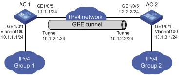
Network requirements
As shown in Figure 8, AC 1 and AC 2 are interconnected through the Internet. Two private IPv4 subnets Group 1 and Group 2 are interconnected through a GRE tunnel between the two ACs.
Configuration procedure
Before the configuration, make sure AC 1 and AC 2 can reach each other.
1. Configure AC 1:
# Add the LAN interface GigabitEthernet 1/0/1 to VLAN 100.
<AC1> system-view
[AC1] vlan 100
[AC1-vlan100] port gigabitethernet 1/0/1
[AC1-vlan100] quit
# Configure an IPv4 address for VLAN-interface 100.
[AC1] interface vlan-interface 100
[AC1-Vlan-interface100] ip address 10.1.1.1 255.255.255.0
[AC1-Vlan-interface100] quit
# Configure an IPv4 address for the WAN interface GigabitEthernet 1/0/5.
[AC1] interface GigabitEthernet 1/0/5
[AC1-GigabitEthernet1/0/5] ip address 1.1.1.1 255.255.255.0
[AC1-GigabitEthernet1/0/5] quit
# Create a tunnel interface named Tunnel1.
[AC1] interface tunnel 1
# Configure an IPv4 address for the tunnel interface Tunnel1.
[AC1-Tunnel1] ip address 10.1.2.1 255.255.255.0
# Configure the tunnel encapsulation mode as GRE over IPv4.
[AC1-Tunnel1] tunnel-protocol gre
# Configure the source address of the tunnel interface Tunnel1 as the IP address of GigabitEthernet 1/0/5.
[AC1-Tunnel1] source GigabitEthernet 1/0/5
# Configure the destination address of the tunnel interface Tunnel1 as the IP address of GigabitEthernet 1/0/5 on AC 2.
[AC1-Tunnel1] destination 2.2.2.2
[AC1-Tunnel1] quit
# Configure a static route from AC 1 through the tunnel interface Tunnel1 to Group 2.
[AC1] ip route-static 10.1.3.0 255.255.255.0 tunnel 1
2. Configure AC 2:
# Add the LAN interface GigabitEthernet 1/0/1 to VLAN 100.
<AC2> system-view
[AC2] vlan 100
[AC2-vlan100] port gigabitethernet 1/0/1
[AC2-vlan100] quit
# Configure an IPv4 address for VLAN-interface 100.
[AC2] interface vlan-interface 100
[AC2-Vlan-interface100] ip address 10.1.3.1 255.255.255.0
[AC2-Vlan-interface100] quit
# Configure an IPv4 address for the WAN interface GigabitEthernet 1/0/5.
[AC2] GigabitEthernet1/0/5
[AC2-GigabitEthernet1/0/5] ip address 2.2.2.2 255.255.255.0
[AC2-GigabitEthernet1/0/5] quit
# Create a tunnel interface named Tunnel1.
[AC2] interface tunnel 1
# Configure an IPv4 address for the tunnel interface Tunnel1.
[AC2-Tunnel1] ip address 10.1.2.2 255.255.255.0
# Configure the tunnel encapsulation mode as GRE over IPv4.
[AC2-Tunnel1] tunnel-protocol gre
# Configure the source address of the tunnel interface Tunnel1 as the IP address of GigabitEthernet 1/0/5.
[AC2-Tunnel1] source GigabitEthernet 1/0/5
# Configure the destination address of the tunnel interface Tunnel1 as the IP address of GigabitEthernet 1/0/5 on AC 1.
[AC2-Tunnel1] destination 1.1.1.1
[AC2-Tunnel1] quit
# Configure a static route from AC 2 through the tunnel interface Tunnel1 to Group 1.
[AC2] ip route-static 10.1.1.0 255.255.255.0 Tunnel 1
3. Verify the configuration:
# Display the tunnel interface status on AC 1 and AC 2.
[AC1] display interface tunnel 1
Tunnel1 current state: UP
Line protocol current state: UP
Description: Tunnel1 Interface
The Maximum Transmit Unit is 1476
Internet Address is 10.1.2.1/24 Primary
Encapsulation is TUNNEL, service-loopback-group ID is 1.
Tunnel source 1.1.1.1, destination 2.2.2.2
Tunnel keepalive disabled
Tunnel protocol/transport GRE/IP
GRE key disabled
Checksumming of GRE packets disabled
Last clearing of counters: Never
Last 300 seconds input: 0 bytes/sec, 0 packets/sec
Last 300 seconds output: 0 bytes/sec, 0 packets/sec
10 packets input, 840 bytes
0 input error
10 packets output, 840 bytes
0 output error
[AC2] display interface tunnel 1
Tunnel1 current state: UP
Line protocol current state: UP
Description: Tunnel1 Interface
The Maximum Transmit Unit is 1476
Internet Address is 10.1.2.2/24 Primary
Encapsulation is TUNNEL, service-loopback-group ID is 1.
Tunnel source 2.2.2.2, destination 1.1.1.1
Tunnel keepalive disabled
Tunnel protocol/transport GRE/IP
GRE key disabled
Checksumming of GRE packets disabled
Last clearing of counters: Never
Last 300 seconds input: 2 bytes/sec, 0 packets/sec
Last 300 seconds output: 2 bytes/sec, 0 packets/sec
10 packets input, 840 bytes
0 input error
10 packets output, 840 bytes
0 output error
# From AC 2, ping the IP address of VLAN-interface 100 on AC 1.
[AC2] ping 10.1.1.1
PING 10.1.1.1: 56 data bytes, press CTRL_C to break
Reply from 10.1.1.1: bytes=56 Sequence=1 ttl=255 time=2 ms
Reply from 10.1.1.1: bytes=56 Sequence=2 ttl=255 time=2 ms
Reply from 10.1.1.1: bytes=56 Sequence=3 ttl=255 time=2 ms
Reply from 10.1.1.1: bytes=56 Sequence=4 ttl=255 time=2 ms
Reply from 10.1.1.1: bytes=56 Sequence=5 ttl=255 time=2 ms
--- 10.1.1.1 ping statistics ---
5 packet(s) transmitted
5 packet(s) received
0.00% packet loss
round-trip min/avg/max = 2/2/2 ms
GRE over IPv6 tunnel configuration example
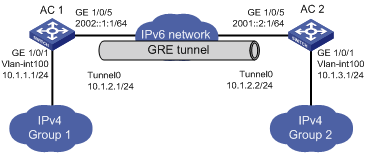
Network requirements
As shown in Figure 9, two IPv4 subnets Group 1 and Group 2 are connected to an IPv6 network. Create a GRE over IPv6 tunnel between AC 1 and AC 2, so that the two IPv4 subnets can communicate with each other through the GRE tunnel over the IPv6 network.
Configuration procedure
Before the configuration, make sure AC 1 and AC 2 can reach each other.
1. Configure AC 1:
<AC1> system-view
# Enable IPv6.
[AC1] ipv6
# Add the LAN interface GigabitEthernet 1/0/1 to VLAN 100.
[AC1] vlan 100
[AC1-vlan100] port gigabitethernet 1/0/1
[AC1-vlan100] quit
# Configure an IPv4 address for VLAN-interface 100.
[AC1] interface vlan-interface 100
[AC1-Vlan-interface100] ip address 10.1.1.1 255.255.255.0
[AC1-Vlan-interface100] quit
# Configure an IPv6 address for the WAN interface GigabitEthernet 1/0/5.
[AC1] GigabitEthernet1/0/5
[AC1-GigabitEthernet1/0/5] ip address 2002::1:1 64
[AC1-GigabitEthernet1/0/5] quit
# Create a tunnel interface named Tunnel 0.
[AC1] interface tunnel 0
# Configure an IPv4 address for interface Tunnel0.
[AC1-Tunnel0] ip address 10.1.2.1 255.255.255.0
# Configure the tunnel encapsulation mode as GRE over IPv6.
[AC1-Tunnel0] tunnel-protocol gre ipv6
# Configure the source address of the tunnel interface Tunnel0 as the IP address of the interface GigabitEthernet 1/0/5.
[AC1-Tunnel0] source 2002::1:1
# Configure the destination address of the tunnel interface Tunnel0 as the IP address of the interface GigabitEthernet 1/0/5 on AC 2.
[AC1-Tunnel0] destination 2001::2:1
[AC1-Tunnel0] quit
# Configure a static route from AC 1 through the tunnel interface Tunnel0 to Group 2.
[AC1] ip route-static 10.1.3.0 255.255.255.0 tunnel 0
2. Configure AC 2:
<AC2> system-view
# Enable IPv6.
[AC2] ipv6
# Add the LAN interface GigabitEthernet 1/0/1 to VLAN 100.
[AC2] vlan 100
[AC2-vlan100] port gigabitethernet 1/0/1
[AC2-vlan100] quit
# Configure an IPv4 address for VLAN-interface 100.
[AC2] interface vlan-interface 100
[AC2-Vlan-interface100] ip address 10.1.3.1 255.255.255.0
[AC2-Vlan-interface100] quit
# Configure an IPv6 address for the WAN interface GigabitEthernet 1/0/5.
[AC2] GigabitEthernet1/0/5
[AC2-GigabitEthernet1/0/5] ipv6 address 2001::2:1 64
[AC2-GigabitEthernet1/0/5] quit
# Create a tunnel interface named Tunnel0.
[AC2] interface tunnel 0
# Configure an IPv4 address for the tunnel interface Tunnel0.
[AC2-Tunnel0] ip address 10.1.2.2 255.255.255.0
# Configure the tunnel encapsulation mode as GRE over IPv6.
[AC2-Tunnel0] tunnel-protocol gre ipv6
# Configure the source address of the tunnel interface Tunnel0 as the IP address of interface GigabitEthernet 1/0/5.
[AC2-Tunnel0] source 2001::2:1
# Configure the destination address of the tunnel interface Tunnel0 as the IP address of interface GigabitEthernet 1/0/5 on AC 1.
[AC2-Tunnel0] destination 2002::1:1
[AC2-Tunnel0] quit
# Configure a static route from AC 2 through the tunnel interface Tunnel0 to Group 1.
[AC2] ip route-static 10.1.1.0 255.255.255.0 tunnel 0
3. Verify the configuration:
# Display the tunnel interface status on AC 1 and AC 2.
[AC1] display interface Tunnel 0
Tunnel0 current state: UP
Line protocol current state: UP
Description: Tunnel0 Interface
The Maximum Transmit Unit is 1456
Internet Address is 10.1.2.1/24 Primary
Encapsulation is TUNNEL, service-loopback-group ID is 1.
Tunnel source 2002::1:1, destination 2001::2:1
Tunnel protocol/transport GRE/IPv6
GRE key disabled
Checksumming of GRE packets disabled
Last clearing of counters: Never
Last 300 seconds input: 0 bytes/sec, 0 packets/sec
Last 300 seconds output: 0 bytes/sec, 0 packets/sec
10 packets input, 840 bytes
0 input error
10 packets output, 840 bytes
0 output error
[AC2] display interface Tunnel 0
Tunnel0 current state: UP
Line protocol current state: UP
Description: Tunnel0 Interface
The Maximum Transmit Unit is 1456
Internet Address is 10.1.2.2/24 Primary
Encapsulation is TUNNEL, service-loopback-group ID is 1.
Tunnel source 2001::2:1, destination 2002::1:1
Tunnel protocol/transport GRE/IPv6
GRE key disabled
Checksumming of GRE packets disabled
Last clearing of counters: Never
Last 300 seconds input: 0 bytes/sec, 0 packets/sec
Last 300 seconds output: 0 bytes/sec, 0 packets/sec
10 packets input, 840 bytes
0 input error
10 packets output, 840 bytes
0 output error
# From AC 2, ping the IP address of VLAN-interface 100 on AC 1.
[AC2] ping 10.1.1.1
PING 10.1.1.1: 56 data bytes, press CTRL_C to break
Reply from 10.1.1.1: bytes=56 Sequence=1 ttl=255 time=3 ms
Reply from 10.1.1.1: bytes=56 Sequence=2 ttl=255 time=2 ms
Reply from 10.1.1.1: bytes=56 Sequence=3 ttl=255 time=2 ms
Reply from 10.1.1.1: bytes=56 Sequence=4 ttl=255 time=2 ms
Reply from 10.1.1.1: bytes=56 Sequence=5 ttl=255 time=3 ms
--- 10.1.1.1 ping statistics ---
5 packet(s) transmitted
5 packet(s) received
0.00% packet loss
round-trip min/avg/max = 2/2/3 ms
Troubleshooting GRE
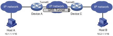
The key to configuring GRE is to keep the configurations consistent. Most faults can be located by using the debugging gre or debugging tunnel command. This section analyzes one type of fault for illustration, with the scenario shown in Figure 10.
Symptom
The interfaces at both ends of the tunnel are configured correctly and can ping each other, but Host A and Host B cannot ping each other.
Solution
1. Execute the display ip routing-table command on Device A and Device C to view whether Device A has a route over tunnel 0 to 10.2.0.0/16 and whether Device C has a route over tunnel 0 to 10.1.0.0/16.
2. If such a route does not exist, execute the ip route-static command in system view to add the route. Take Device A as an example:
[DeviceA] ip route-static 10.2.0.0 255.255.0.0 tunnel 0