- Table of Contents
-
- H3C Fixed Port Campus Switches Configuration Examples-B70D022-6W100
- 01-Login Management Configuration Examples
- 02-RBAC Configuration Examples
- 03-Software Upgrade Examples
- 04-ISSU Configuration Examples
- 05-Software Patching Examples
- 06-Ethernet Link Aggregation Configuration Examples
- 07-Port Isolation Configuration Examples
- 08-Spanning Tree Configuration Examples
- 09-VLAN Configuration Examples
- 10-VLAN Tagging Configuration Examples
- 11-DHCP Snooping Configuration Examples
- 12-Cross-Subnet Dynamic IP Address Allocation Configuration Examples
- 13-IPv6 over IPv4 Manual Tunneling with OSPFv3 Configuration Examples
- 14-ISATAP Tunnel and 6to4 Tunnel Configuration Examples
- 15-GRE Tunnel Configuration Examples
- 16-GRE with OSPF Configuration Examples
- 17-OSPF Configuration Examples
- 18-IS-IS Configuration Examples
- 19-BGP Configuration Examples
- 20-Policy-Based Routing Configuration Examples
- 21-OSPFv3 Configuration Examples
- 22-IPv6 IS-IS Configuration Examples
- 23-Routing Policy Configuration Examples
- 24-IGMP Snooping Configuration Examples
- 25-IGMP Configuration Examples
- 26-BIDIR-PIM Configuration Examples
- 27-Multicast VPN Configuration Examples
- 28-MLD Snooping Configuration Examples
- 29-IPv6 Multicast VLAN Configuration Examples
- 30-Basic MPLS Configuration Examples
- 31-MPLS L3VPN Configuration Examples
- 32-ACL Configuration Examples
- 33-Control Plane-Based QoS Policy Configuration Examples
- 34-Traffic Policing Configuration Examples
- 35-GTS and Rate Limiting Configuration Examples
- 36-Priority Mapping and Queue Scheduling Configuration Examples
- 37-Traffic Filtering Configuration Examples
- 38-AAA Configuration Examples
- 39-Port Security Configuration Examples
- 40-Portal Configuration Examples
- 41-SSH Configuration Examples
- 42-IP Source Guard Configuration Examples
- 43-Ethernet OAM Configuration Examples
- 44-CFD Configuration Examples
- 45-DLDP Configuration Examples
- 46-VRRP Configuration Examples
- 47-BFD Configuration Examples
- 48-NTP Configuration Examples
- 49-SNMP Configuration Examples
- 50-NQA Configuration Examples
- 51-Mirroring Configuration Examples
- 52-sFlow Configuration Examples
- 53-OpenFlow Configuration Examples
- 54-MAC Address Table Configuration Examples
- 55-Static Multicast MAC Address Entry Configuration Examples
- 56-IP Unnumbered Configuration Examples
- 57-MVRP Configuration Examples
- 58-MCE Configuration Examples
- 59-Congestion Avoidance and Queue Scheduling Configuration Examples
- 60-Attack Protection Configuration Examples
- 61-Smart Link Configuration Examples
- 62-RRPP Configuration Examples
- 63-BGP Route Selection Configuration Examples
- 64-IS-IS Route Summarization Configuration Examples
- 65-IRF Configuration Examples
- 66-MPLS TE Configuration Examples
- 67-VXLAN Configuration Examples
- 68-VCF Fabric Configuration Examples
- Related Documents
-
| Title | Size | Download |
|---|---|---|
| 58-MCE Configuration Examples | 308.22 KB |
Example: Configuring the MCE to advertise VPN routes to the PE by using OSPF (on switches)
Applicable hardware and software versions
Example: Configuring the MCE to advertise VPN routes to the PE by using BGP (on switches)
Applicable hardware and software versions
Introduction
This document provides examples for configuring the MCE to advertise VPN routes to the PE.
Prerequisites
This document is not restricted to specific software or hardware versions.
The configuration examples in this document were created and verified in a lab environment, and all the devices were started with the factory default configuration. When you are working on a live network, make sure you understand the potential impact of every command on your network.
This document assumes that you have basic knowledge of MCE.
Example: Configuring the MCE to advertise VPN routes to the PE by using OSPF (on switches)
Network configuration
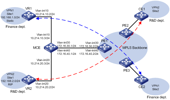
As shown in Figure 1, an enterprise has two MPLS L3VPNs. VPN 1 for the finance department uses static routes, and VPN 2 for the R&D department uses RIP routes. Site 1 of VPN 1 and Site 1 of VPN 2 are connected to the MPLS backbone through the same CE device (MCE). Site 2 of VPN 1 and Site 2 of VPN 2 are connected to the MPLS backbone through separate CEs (CE 1 and CE 2).
Configure the MCE to allow communication between the local and remote sites of the same VPN and isolate access between sites of different VPNs.
Configure the MCE and PE 1 to use OSPF to exchange VPN routes.
Analysis
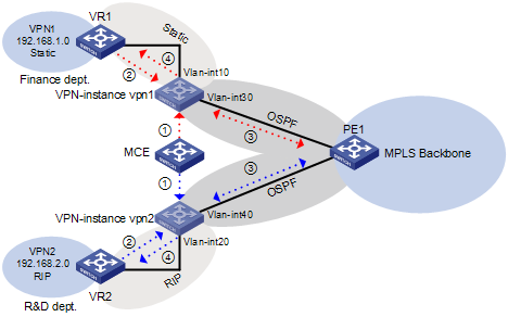
To meet the network requirements, you must perform the following tasks:
1. Create VPN instances on the MCE and PE 1, and bind each VPN instance to the interfaces that need to forward data for that VPN instance.
2. Redistribute the VPN routes to the routing table of the corresponding VPN instance.
3. Advertise the VPN routes to PE 1 through OSPF, and receive remote VPN routes from PE 1.
4. Redistribute the remote VPN routes to the local VPN sites.
Figure 2 Network diagram
Applicable hardware and software versions
The following matrix shows the hardware and software versions to which this configuration example is applicable:
|
Hardware |
Software version |
|
S6520XE-HI switch series |
Supported in Release 11xx |
|
S5560X-EI switch series |
Supported in Release 111x |
|
S5500V2-EI switch series |
Supported in Release 111x |
|
MS4520V2-30F switch |
Supported in Release 111x |
|
S5560S-EI switch series S5560S-SI switch series |
Supported in Release 612x |
|
S5130S-HI switch series S5130S-EI switch series S5130S-SI switch series S5130S-LI switch series |
Not supported |
|
S5120V2-SI switch series S5120V2-LI switch series |
Not supported |
|
S3100V3-EI switch series S3100V3-SI switch series |
Not supported |
|
S5110V2 switch series |
Not supported |
|
S5110V2-SI switch series |
Not supported |
|
S5000V3-EI switch series |
Not supported |
|
S5000E-X switch series |
Not supported |
|
WAS6000 switch series |
Not supported |
|
E128C switch E152C switch E500C switch series E500D switch series |
Not supported |
|
MS4520V2 switch series (except the MS4520V2-30F switch) |
Supported in Release 612x |
|
MS4320V2 switch series MS4300V2 switch series MS4320 switch series MS4200 switch series |
Not supported |
|
WS5850-WiNet switch series |
Supported in Release 612x |
|
WS5820-WiNet switch series WS5810-WiNet switch series |
Not supported |
Restrictions and guidelines
Follow these restrictions and guidelines when you configure the MCE to advertise VPN routes to the PE by using OSPF:
· Associating an interface with a VPN instance by using the ip binding vpn-instance command deletes the IP address of the interface. You must reconfigure the interface's IP address after the association.
· An OSPF process can belong to only one VPN instance, but a VPN instance can use multiple OSPF processes to advertise private routes. The OSPF processes in a VPN instance must have the same domain ID to ensure correct route advertisement.
Procedures
This example provides only the configurations on the MCE, VR 1, VR 2, and PE 1. Configurations on other devices are not shown.
1. Configure VPN instances on the MCE and PE 1:
# On the MCE, create a VPN instance named vpn1, and configure its RD as 10:1.
<MCE> system-view
[MCE] ip vpn-instance vpn1
[MCE-vpn-instance-vpn1] route-distinguisher 10:1
[MCE-vpn-instance-vpn1] quit
# Create a VPN instance named vpn2, and configure its RD as 20:1.
[MCE] ip vpn-instance vpn2
[MCE-vpn-instance-vpn2] route-distinguisher 20:1
[MCE-vpn-instance-vpn2] quit
# Bind VLAN-interface 10 to the VPN instance vpn1, and configure an IP address for the interface.
[MCE] interface Vlan-interface 10
[MCE-Vlan-interface10] ip binding vpn-instance vpn1
[MCE-Vlan-interface10] ip address 10.214.10.3 24
[MCE-Vlan-interface10] quit
[MCE-Vlan-interface10] quit
# Bind VLAN-interface 20 to the VPN instance vpn2, and configure an IP address for the interface.
[MCE] interface Vlan-interface 20
[MCE-Vlan-interface20] ip binding vpn-instance vpn2
[MCE-Vlan-interface20] ip address 10.214.20.3 24
[MCE-Vlan-interface20] quit
# Bind VLAN-interface 30 to the VPN instance vpn1, and configure an IP address for the interface.
[MCE] interface Vlan-interface 30
[MCE-Vlan-interface30] ip binding vpn-instance vpn1
[MCE-Vlan-interface30] ip address 172.16.30.1 24
[MCE-Vlan-interface30] quit
# Bind VLAN-interface 40 to the VPN instance vpn2, and configure an IP address for the interface.
[MCE] interface Vlan-interface 40
[MCE-Vlan-interface40] ip binding vpn-instance vpn2
[MCE-Vlan-interface40] ip address 172.16.40.1 24
[MCE-Vlan-interface40] quit
# On PE 1, create VPN instances vpn1 and vpn2, and configure RDs for the VPN instances. Make sure the RDs are the same as those configured on the MCE.
[PE1] ip vpn-instance vpn1
[PE1-vpn-instance-vpn1] route-distinguisher 10:1
[PE1-vpn-instance-vpn1] quit
[PE1] ip vpn-instance vpn2
[PE1-vpn-instance-vpn2] route-distinguisher 20:1
[PE1-vpn-instance-vpn2] quit
# Bind VLAN-interface 30 to the VPN instance vpn1 and VLAN-interface 40 to the VPN instance vpn2, and configure IP addresses for the interfaces.
[PE1] interface vlan-interface 30
[PE1-Vlan-interface30] ip binding vpn-instance vpn1
[PE1-Vlan-interface30] ip address 172.16.30.2 24
[PE1-Vlan-interface30] quit
[PE1] interface vlan-interface 40
[PE1-Vlan-interface40] ip binding vpn-instance vpn2
[PE1-Vlan-interface40] ip address 172.16.40.2 24
[PE1-Vlan-interface40] quit
2. Configure routing between the MCE and VPN sites:
# On VR 1, assign IP address 10.214.10.2/24 to the interface connected to the MCE. (Details not shown.)
# On VR 1, configure a default route with the next hop as the MCE.
<VR1> system-view
[VR1] ip route-static 0.0.0.0 0.0.0.0 10.214.10.3
# On the MCE, configure a static route to 192.168.1.0/24 with the next hop 10.214.10.2, and bind the static route to the VPN instance vpn1.
[MCE] ip route-static vpn-instance vpn1 192.168.1.0 24 10.214.10.2
# On the MCE, display the routing table for the VPN instance vpn1.
[MCE] display ip routing-table vpn-instance vpn1
Destinations : 7 Routes : 7
Destination/Mask Proto Pre Cost NextHop Interface
10.214.10.0/24 Direct 0 0 10.214.10.3 Vlan10
10.214.10.3/32 Direct 0 0 127.0.0.1 InLoop0
127.0.0.0/8 Direct 0 0 127.0.0.1 InLoop0
127.0.0.1/32 Direct 0 0 127.0.0.1 InLoop0
172.16.30.0/24 Direct 0 0 172.16.30.1 Vlan30
172.16.30.1/32 Direct 0 0 127.0.0.1 InLoop0
192.168.1.0/24 Static 60 0 10.214.10.2 Vlan10
The output shows that the MCE has a static route for the VPN instance vpn1.
# On VR 2, assign IP address 10.214.20.2/24 to the interface connected to the MCE. (Details not shown.)
# On VR 2, enable RIP process 20 to advertise networks 192.168.2.0/24 and 10.214.20.0/24, and disable route summarization.
<VR2> system-view
[VR2] rip 20
[VR2-rip-20] network 192.168.2.0
[VR2-rip-20] network 10.0.0.0
[VR2-rip-20] undo summary
# On the MCE, enable RIP process 20 for the VPN instance vpn2 to exchange routes with VPN 2 site 1.
[MCE] rip 20 vpn-instance vpn2
# On the MCE, advertise the network 10.214.20.0 and disable route summarization.
[MCE-rip-20] network 10.0.0.0
[MCE-rip-20] undo summary
# On the MCE, redistribute OSPF routes.
[MCE-rip-20] import-route ospf 20
[MCE-rip-20] quit
# On the MCE, display the routing table for the VPN instance vpn2.
[MCE] display ip routing-table vpn-instance vpn2
Destinations : 5 Routes : 5
Destination/Mask Proto Pre Cost NextHop Interface
10.214.20.0/24 Direct 0 0 10.214.20.3 Vlan20
10.214.20.3/32 Direct 0 0 127.0.0.1 InLoop0
127.0.0.0/8 Direct 0 0 127.0.0.1 InLoop0
127.0.0.1/32 Direct 0 0 127.0.0.1 InLoop0
172.16.40.0/30 Direct 0 0 172.16.40.1 Vlan40
172.16.40.1/32 Direct 0 0 127.0.0.1 InLoop0
192.168.2.0/24 RIP 100 1 10.214.20.2 Vlan20
The output shows that the MCE has learned a RIP route to VPN 2, which is in a different routing table from the static route to VPN 1. The routes from different VPNs are separated.
3. Configure routing between the MCE and PE 1:
# On the MCE, bind Loopback 0 to the VPN instance vpn1 and configure an IP address for the loopback interface.
[MCE] interface Loopback 0
[MCE-Loopback0] ip binding vpn-instance vpn1
[MCE-Loopback0] ip address 100.100.10.1 32
[MCE-Loopback0] quit
# On PE 1, bind Loopback 0 to the VPN instance vpn1 and configure an IP address for the loopback interface.
[PE1] interface Loopback 0
[PE1-Loopback0] ip binding vpn-instance vpn1
[PE1-Loopback0] ip address 100.100.11.1 32
[PE1-Loopback0] quit
# On the MCE, enable OSPF process 10, specify the router ID as the IP address of Loopback 0, and bind the process to the VPN instance vpn1.
[MCE] ospf 10 router-id 100.100.10.1 vpn-instance vpn1
# Disable routing loop detection for OSPF process 10.
[MCE-ospf-10] vpn-instance-capability simple
# Advertise the network 172.16.30.0/24 in area 0, and redistribute the static route of VPN 1.
[MCE-ospf-10] area 0
[MCE-ospf-10-area-0.0.0.0] network 172.16.30.0 0.0.0.255
[MCE-ospf-10-area-0.0.0.0] quit
[MCE-ospf-10] import-route static
[MCE-ospf-10] quit
# On PE 1, enable OSPF process 10, specify the router ID as the IP address of Loopback 0, and bind the process to the VPN instance vpn1.
[PE1] ospf 10 router-id 100.100.11.1 vpn-instance vpn1
# Set the domain ID to 10.
[PE1-ospf-10] domain-id 10
# Disable routing loop detection for OSPF process 10.
[PE1-ospf-10] vpn-instance-capability simple
# Advertise the network 172.16.30.0/24 in area 0.
[PE1-ospf-10] area 0
[PE1-ospf-10-area-0.0.0.0] network 172.16.30.0 0.0.0.255
# On the MCE, bind Loopback 1 to the VPN instance vpn2 and configure an IP address for the loopback interface.
[MCE] interface Loopback 1
[MCE-Loopback1] ip binding vpn-instance vpn2
[MCE-Loopback1] ip address 100.100.20.1 32
# On PE 1, bind Loopback 1 to the VPN instance vpn2 and configure an IP address for the loopback interface.
[PE1] interface Loopback 1
[PE1-Loopback1] ip binding vpn-instance vpn2
[PE1-Loopback1] ip address 100.100.21.1 32
# On the MCE, enable OSPF process 20, specify the router ID as the IP address of Loopback 1, and bind the process to the VPN instance vpn2.
[MCE] ospf 20 router-id 100.100.20.1 vpn-instance vpn2
# Disable routing loop detection for OSPF process 20.
[MCE-ospf-20] vpn-instance-capability simple
# Advertise the network 172.16.40.0/24 in area 0, and redistribute the RIP route of VPN 2.
[MCE-ospf-20] area 0
[MCE-ospf-20-area-0.0.0.0] network 172.16.40.0 0.0.0.255
[MCE-ospf-20-area-0.0.0.0] quit
[MCE-ospf-20] import-route rip 20
# On PE 1, enable OSPF process 20, specify the router ID as the IP address of Loopback 1, and bind the process to the VPN instance vpn2.
[PE1] ospf 20 router-id 100.100.21.1 vpn-instance vpn2
# Set the domain ID to 20.
[PE1-ospf-20] domain-id 20
# Disable routing loop detection for OSPF process 20.
[PE1-ospf-20] vpn-instance-capability simple
# Advertise the network 172.16.40.0/24 in area 0.
[PE1-ospf-20] area 0
[PE1-ospf-20-area-0.0.0.0] network 172.16.40.0 0.0.0.255
[PE1-ospf-20-area-0.0.0.0] quit
Verifying the configuration
# Verify that PE 1 has learned the static route of VPN 1 through OSPF.
[PE1] display ip routing-table vpn-instance vpn1
Destinations : 14 Routes : 14
Destination/Mask Proto Pre Cost NextHop Interface
0.0.0.0/32 Direct 0 0 127.0.0.1 InLoop0
100.100.11.1/32 Direct 0 0 127.0.0.1 InLoop0
127.0.0.0/8 Direct 0 0 127.0.0.1 InLoop0
127.0.0.0/32 Direct 0 0 127.0.0.1 InLoop0
127.0.0.1/32 Direct 0 0 127.0.0.1 InLoop0
127.255.255.255/32 Direct 0 0 127.0.0.1 InLoop0
172.16.30.0/24 Direct 0 0 172.16.30.2 Vlan30
172.16.30.0/32 Direct 0 0 172.16.30.2 Vlan30
172.16.30.2/32 Direct 0 0 127.0.0.1 InLoop0
172.16.30.255/32 Direct 0 0 172.16.30.2 Vlan30
192.168.1.0/24 O_INTRA 150 1 172.16.30.1 Vlan30
224.0.0.0/4 Direct 0 0 0.0.0.0 NULL0
224.0.0.0/24 Direct 0 0 0.0.0.0 NULL0
255.255.255.255/32 Direct 0 0 127.0.0.1 InLoop0
# Verify that PE 1 has learned the RIP route of VPN 2 through OSPF.
[PE1] display ip routing-table vpn-instance vpn2
Destinations : 14 Routes : 14
Destination/Mask Proto Pre Cost NextHop Interface
0.0.0.0/32 Direct 0 0 127.0.0.1 InLoop0
100.100.21.1/32 Direct 0 0 127.0.0.1 InLoop0
127.0.0.0/8 Direct 0 0 127.0.0.1 InLoop0
127.0.0.0/32 Direct 0 0 127.0.0.1 InLoop0
127.0.0.1/32 Direct 0 0 127.0.0.1 InLoop0
127.255.255.255/32 Direct 0 0 127.0.0.1 InLoop0
172.16.40.0/24 Direct 0 0 172.16.40.2 Vlan40
172.16.40.0/32 Direct 0 0 172.16.40.2 Vlan40
172.16.40.2/32 Direct 0 0 127.0.0.1 InLoop0
172.16.40.255/32 Direct 0 0 172.16.40.2 Vlan40
192.168.2.0/24 O_INTRA 150 1 172.16.40.1 Vlan40
224.0.0.0/4 Direct 0 0 0.0.0.0 NULL0
224.0.0.0/24 Direct 0 0 0.0.0.0 NULL0
255.255.255.255/32 Direct 0 0 127.0.0.1 InLoop0
Configuration files
· VR 1:
#
vlan 10
#
interface Vlan-interface10
ip address 10.214.10.2 255.255.255.0
#
ip route-static 0.0.0.0 0 10.214.10.3
#
· VR 2:
#
rip 20
network 10.0.0.0
network 192.168.2.0
#
vlan 20
#
interface Vlan-interface20
ip address 10.214.20.2 255.255.255.0
#
· MCE:
#
ip vpn-instance vpn1
route-distinguisher 10:1
#
ip vpn-instance vpn2
route-distinguisher 20:1
#
ospf 10 router-id 100.100.10.1 vpn-instance vpn1
import-route static
vpn-instance-capability simple
area 0.0.0.0
network 172.16.30.0 0.0.0.255
#
ospf 20 router-id 100.100.20.1 vpn-instance vpn2
import-route rip 20
vpn-instance-capability simple
area 0.0.0.0
network 172.16.40.0 0.0.0.255
#
rip 20 vpn-instance vpn2
undo summary
network 10.0.0.0
import-route ospf 20
#
vlan 10
#
vlan 20
#
vlan 30
#
vlan 40
#
interface LoopBack0
ip binding vpn-instance vpn1
ip address 100.100.10.1 255.255.255.255
#
interface LoopBack1
ip binding vpn-instance vpn2
ip address 100.100.20.1 255.255.255.255
#
interface Vlan-interface10
ip binding vpn-instance vpn1
ip address 10.214.10.3 255.255.255.0
#
interface Vlan-interface20
ip binding vpn-instance vpn2
ip address 10.214.20.3 255.255.255.0
#
interface Vlan-interface30
ip binding vpn-instance vpn1
ip address 172.16.30.1 255.255.255.0
#
interface Vlan-interface40
ip binding vpn-instance vpn2
ip address 172.16.40.1 255.255.255.0
#
ip route-static vpn-instance vpn1 192.168.1.0 255.255.255.0 10.214.10.2
#
· PE 1:
#
ip vpn-instance vpn1
route-distinguisher 10:1
#
ip vpn-instance vpn2
route-distinguisher 20:1
#
ospf 10 router-id 100.100.10.1 vpn-instance vpn1
domain-id 0.0.0.10
vpn-instance-capability simple
area 0.0.0.0
network 172.16.30.0 0.0.0.255
#
ospf 20 router-id 100.100.20.1 vpn-instance vpn2
domain-id 0.0.0.20
vpn-instance-capability simple
area 0.0.0.0
network 172.16.40.0 0.0.0.255
#
vlan 30
#
vlan 40
#
interface LoopBack0
ip binding vpn-instance vpn1
ip address 100.100.11.1 255.255.255.255
#
interface LoopBack1
ip binding vpn-instance vpn2
ip address 100.100.21.1 255.255.255.255
#
interface Vlan-interface30
ip binding vpn-instance vpn1
ip address 172.16.30.2 255.255.255.0
#
interface Vlan-interface40
ip binding vpn-instance vpn2
ip address 172.16.40.2 255.255.255.0
#
Example: Configuring the MCE to advertise VPN routes to the PE by using BGP (on switches)
Network configuration
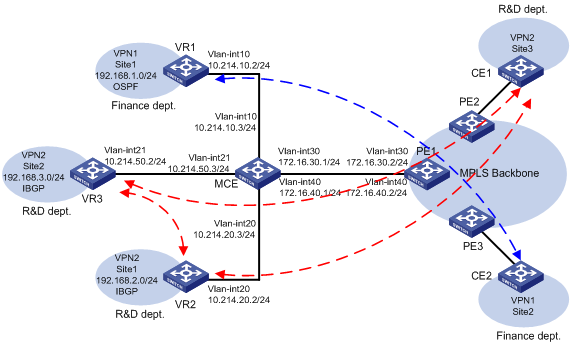
As shown in Figure 3, an enterprise has two MPLS L3VPNs. VPN 1 for the finance department uses OSPF, and VPN 2 for the R&D department uses IBGP. Site 1 of VPN 1, Site 2 of VPN 2, and Site 1 of VPN 2 are connected to the MPLS backbone through the same CE device (MCE). Site 3 of VPN 2 and Site 2 of VPN 1 are connected to the MPLS backbone through separate CEs (CE 1 and CE 2).
Configure the MCE to allow communication between the local and remote sites of the same VPN and isolate access between sites of different VPNs.
Configure the MCE and PE 1 to use BGP to exchange VPN routes.
Analysis
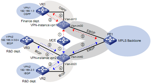
To meet the network requirements, you must perform the following tasks:
1. Create VPN instances on the MCE and PE 1, and bind each VPN instance to the interfaces that need to forward data for that VPN instance.
2. Redistribute the VPN routes to the routing table of the corresponding VPN instance.
IBGP requires a fully meshed network or a router reflector. In this example, you must configure the MCE as the IBGP route reflector.
3. Advertise the VPN routes to PE 1 through EBGP, and receive remote VPN routes from PE 1.
4. Redistribute the remote VPN routes to the local VPN sites.
Applicable hardware and software versions
The following matrix shows the hardware and software versions to which this configuration example is applicable:
|
Hardware |
Hardware |
|
S6520XE-HI switch series |
Supported in Release 11xx |
|
S5560X-EI switch series |
Supported in Release 111x |
|
S5500V2-EI switch series |
Supported in Release 111x |
|
MS4520V2-30F switch |
Supported in Release 111x |
|
S5560S-EI switch series S5560S-SI switch series |
Supported in Release 612x |
|
S5130S-HI switch series S5130S-EI switch series S5130S-SI switch series S5130S-LI switch series |
Not supported |
|
S5120V2-SI switch series S5120V2-LI switch series |
Not supported |
|
S3100V3-EI switch series S3100V3-SI switch series |
Not supported |
|
S5110V2 switch series |
Not supported |
|
S5110V2-SI switch series |
Not supported |
|
S5000V3-EI switch series |
Not supported |
|
S5000E-X switch series |
Not supported |
|
WAS6000 switch series |
Not supported |
|
E128C switch E152C switch E500C switch series E500D switch series |
Not supported |
|
MS4520V2 switch series (except the MS4520V2-30F switch) |
Supported in Release 612x |
|
MS4320V2 switch series MS4300V2 switch series MS4320 switch series MS4200 switch series |
Not supported |
|
WS5850-WiNet switch series |
Supported in Release 612x |
|
WS5820-WiNet switch series WS5810-WiNet switch series |
Not supported |
Restrictions and guidelines
Associating an interface with a VPN instance by using the ip binding vpn-instance command deletes the IP address of the interface. You must reconfigure the interface's IP address after the association.
Procedures
This example provides only the configurations on the MCE, VR 1, VR 2, VR 3, and PE 1. Configurations on other devices are not shown.
1. Configure VPN instances on the MCE and PE 1:
# On the MCE, create a VPN instance named vpn1, and configure its RD as 10:1.
<MCE> system-view
[MCE] ip vpn-instance vpn1
[MCE-vpn-instance-vpn1] route-distinguisher 10:1
[MCE-vpn-instance-vpn1] quit
# Create a VPN instance named vpn2, and configure its RD as 20:1.
[MCE] ip vpn-instance vpn2
[MCE-vpn-instance-vpn2] route-distinguisher 20:1
[MCE-vpn-instance-vpn2] quit
# Bind VLAN-interface 10 to the VPN instance vpn1, and configure an IP address for the interface.
[MCE] interface Vlan-interface 10
[MCE-Vlan-interface10] ip binding vpn-instance vpn1
[MCE-Vlan-interface10] ip address 10.214.10.3 24
[MCE-Vlan-interface10] quit
# Bind VLAN-interface 20 to the VPN instance vpn2, and configure an IP address for the interface.
[MCE] interface Vlan-interface 20
[MCE-Vlan-interface20] ip binding vpn-instance vpn2
[MCE-Vlan-interface20] ip address 10.214.20.3 24
[MCE-Vlan-interface20] quit
# Bind VLAN-interface 21 to the VPN instance vpn2, and configure an IP address for the interface.
[MCE] interface Vlan-interface 21
[MCE-Vlan-interface21] ip binding vpn-instance vpn2
[MCE-Vlan-interface21] ip address 10.214.50.3 24
[MCE-Vlan-interface21] quit
# Bind VLAN-interface 30 to the VPN instance vpn1, and configure an IP address for the interface.
[MCE] interface Vlan-interface 30
[MCE-Vlan-interface30] ip binding vpn-instance vpn1
[MCE-Vlan-interface30] ip address 172.16.30.1 24
[MCE-Vlan-interface30] quit
# Bind VLAN-interface 40 to the VPN instance vpn2, and configure an IP address for the interface.
[MCE] interface Vlan-interface 40
[MCE-Vlan-interface40] ip binding vpn-instance vpn2
[MCE-Vlan-interface40] ip address 172.16.40.1 24
[MCE-Vlan-interface40] quit
# On PE 1, create VPN instances vpn1 and vpn2, and configure RDs for the VPN instances. Make sure the RDs are the same as those configured on the MCE.
[PE1] ip vpn-instance vpn1
[PE1-vpn-instance-vpn1] route-distinguisher 10:1
[PE1-vpn-instance-vpn1] quit
[PE1] ip vpn-instance vpn2
[PE1-vpn-instance-vpn2] route-distinguisher 20:1
[PE1-vpn-instance-vpn2] quit
# Bind VLAN-interface 30 to the VPN instance vpn1 and VLAN-interface 40 to the VPN instance vpn2, and configure IP addresses for the interfaces.
[PE1] interface vlan-interface 30
[PE1-Vlan-interface30] ip binding vpn-instance vpn1
[PE1-Vlan-interface30] ip address 172.16.30.2 24
[PE1-Vlan-interface30] quit
[PE1] interface vlan-interface 40
[PE1-Vlan-interface40] ip binding vpn-instance vpn2
[PE1-Vlan-interface40] ip address 172.16.40.2 24
[PE1-Vlan-interface40] quit
2. Configure routing between the MCE and VPN sites:
# On VR 1, assign IP address 10.214.10.2/24 to the interface connected to the MCE. (Details not shown.)
# On VR 1, enable OSPF, and advertise networks 192.168.1.0/24 and 10.214.10.2/24.
<VR1> system-view
[VR1] ospf
[VR1-ospf-1] area 0
[VR1-ospf-1-area-0.0.0.0] network 192.168.1.0 0.0.0.255
[VR1-ospf-1-area-0.0.0.0] network 10.214.10.0 0.0.0.255
# On the MCE, bind Loopback 0 to the VPN instance vpn1 and configure an IP address for the loopback interface.
[MCE] interface LoopBack 0
[MCE-LoopBack0] ip binding vpn-instance vpn1
[MCE-LoopBack0] ip address 101.101.10.1 32
[MCE-LoopBack0] quit
# On the MCE, enable OSPF process 1, bind the process to the VPN instance vpn1, and specify the router ID as the IP address of Loopback 0.
[MCE] ospf 1 vpn-instance vpn1 router-id 101.101.10.1
# On the MCE, advertise the network 10.214.10.0/24.
[MCE-ospf-1] area 0
[MCE-ospf-1-area-0.0.0.0] network 10.214.10.0 0.0.0.255
[MCE-ospf-1-area-0.0.0.0] quit
[MCE-ospf-1] quit
# On the MCE, display the routing table for the VPN instance vpn1.
[MCE] display ip routing-table vpn-instance vpn1
Destinations : 6 Routes : 6
Destination/Mask Proto Pre Cost NextHop Interface
0.0.0.0/32 Direct 0 0 127.0.0.1 InLoop0
127.0.0.0/8 Direct 0 0 127.0.0.1 InLoop0
127.0.0.1/32 Direct 0 0 127.0.0.1 InLoop0
10.214.10.0/24 Direct 0 0 10.214.10.3 Vlan10
10.214.10.3/32 Direct 0 0 127.0.0.1 InLoop0
192.168.1.0/24 O_INTRA 10 2 10.214.10.2 Vlan10
The output shows that the MCE has learned an OSPF route to VPN 1 site 1.
# On VR 2, assign IP address 10.214.20.2/24 to the interface connected to the MCE. (Details not shown.)
# On VR 3, assign IP address 10.214.50.2/24 to the interface connected to the MCE. (Details not shown.)
# On VR 2, enable BGP in AS 100, specify 10.214.20.3 (the MCE) as the peer, and advertise networks 192.168.2.0/24 and 10.214.20.0/24.
<VR2> system-view
[VR2] bgp 100
[VR2-bgp-default] router-id 2.2.2.2
[VR2-bgp-default] peer 10.214.20.3 as-number 100
[VR2-bgp-default] address-family ipv4
[VR2-bgp-default-ipv4] peer 10.214.20.3 enable
[VR2-bgp-default-ipv4] network 192.168.2.0 24
[VR2-bgp-default-ipv4] network 10.214.20.0 24
[VR2-bgp-default-ipv4] quit
[VR2-bgp-default] quit
# On VR 3, enable BGP in AS 100, specify 10.214.50.3 (the MCE) as the peer, and advertise networks 192.168.3.0/24 and 10.214.50.0/24.
<VR3> system-view
[VR3] bgp 100
[VR3-bgp-default] router-id 3.3.3.3
[VR3-bgp-default] peer 10.214.50.3 as-number 100
[VR3-bgp-default] address-family ipv4
[VR3-bgp-default-ipv4] peer 10.214.50.3 enable
[VR3-bgp-default-ipv4] network 192.168.3.0 24
[VR3-bgp-default-ipv4] network 10.214.50.0 24
[VR3-bgp-default-ipv4] quit
[VR3-bgp-default] quit
# On the MCE, enable BGP in AS 100, create the BGP-VPN instance vpn2, specify 10.214.20.2 and 10.214.50.2 as the peers, and advertise networks 10.214.20.0/24 and 10.214.50.0/24.
[MCE] bgp 100
[MCE-bgp-default] ip vpn-instance vpn2
[MCE-bgp-default-vpn2] peer 10.214.20.2 as-number 100
[MCE-bgp-default-vpn2] peer 10.214.50.2 as-number 100
[MCE-bgp-default] address-family ipv4
[MCE-bgp-default-ipv4-vpn2] peer 10.214.20.2 enable
[MCE-bgp-default-ipv4-vpn2] peer 10.214.50.2 enable
[MCE-bgp-default-ipv4-vpn2] network 10.214.20.0 24
[MCE-bgp-default-ipv4-vpn2] network 10.214.50.0 24
# Configure the MCE as a route reflector, and specify VR 2 and VR 3 as its clients.
[MCE-bgp-default-ipv4-vpn2] peer 10.214.20.2 reflect-client
[MCE-bgp-default-ipv4-vpn2] peer 10.214.50.2 reflect-client
# On the MCE, display BGP VPNv4 routing information for the BGP instance vpn2.
[MCE-bgp-default-ipv4-vpn2] display bgp routing-table vpnv4
BGP local router ID is 4.4.4.4
Status codes: * - valid, > - best, d - dampened, h - history
s - suppressed, S - stale, i - internal, e – external
a - additional-path
Origin: i - IGP, e - EGP, ? - incomplete
Route distinguisher: 20:1(vpn2)
Total number of routes: 6
Network NextHop MED LocPrf PrefVal Path/Ogn
* > 10.214.20.0/24 10.214.20.3 0 32768 i
* i 10.214.20.2 0 100 0 i
* > 10.214.50.0/24 10.214.50.3 0 32768 i
* i 10.214.50.2 0 100 0 i
* >i 192.168.2.0 10.214.20.2 0 100 0 i
* >i 192.168.3.0 10.214.50.2 0 100 0 i
The output shows that the MCE has learned BGP routes to the sites of VPN 2.
3. Configure routing between the MCE and PE 1:
# On the MCE, create the BGP-VPN instance vpn1, and specify 172.16.30.2 (PE 1) as the EBGP peer in AS 200.
[MCE] bgp 100
[MCE-bgp-default] ip vpn-instance vpn1
[MCE-bgp-default-vpn1] peer 172.16.30.2 as-number 200
# Redistribute OSPF routes for BGP-VPN instance vpn1, and advertise network 172.16.30.0/24.
[MCE-bgp-default-vpn1] address-family ipv4
[MCE-bgp-default-ipv4-vpn1] import-route ospf
[MCE-bgp-default-ipv4-vpn1] peer 172.16.30.2 enable
[MCE-bgp-default-ipv4-vpn1] network 172.16.30.0 24
[MCE-bgp-default-ipv4-vpn1] quit
[MCE-bgp-default-vpn1] quit
# On PE 1, enter the view of the BGP-VPN instance vpn1, specify 172.16.30.1 (the MCE) as the EBGP peer in AS 100, and advertise network 172.16.30.0/24.
[PE1] bgp 200
[PE1-bgp-default] ip vpn-instance vpn1
[PE1-bgp-default-vpn1] peer 172.16.30.1 as-number 100
[PE1-bgp-default-vpn1] address-family ipv4
[PE1-bgp-default-ipv4-vpn1] peer 172.16.30.1 enable
[PE1-bgp-default-ipv4-vpn1] network 172.16.30.0 24
[PE1-bgp-default-ipv4-vpn1] quit
[PE1-bgp-default-vpn1] quit
# On the MCE, enter the view of the BGP-VPN instance vpn2, specify 172.16.40.2 (PE 1) as the EBGP peer in AS 200, and advertise network 172.16.40.0/24.
[MCE-bgp-default] ip vpn-instance vpn2
[MCE-bgp-default-vpn2] peer 172.16.40.2 as-number 200
[MCE-bgp-default-vpn2] address-family ipv4
[MCE-bgp-default-ipv4-vpn2] peer 172.16.40.2 enable
[MCE-bgp-default-ipv4-vpn2] network 172.16.40.0 24
[MCE-bgp-default-ipv4-vpn2] quit
[MCE-bgp-default-vpn2] quit
[MCE-bgp-default] quit
# On PE 1, enter the view of the BGP-VPN instance vpn2, specify 172.16.40.1 (the MCE) as the EBGP peer in AS 100, and advertise network 172.16.40.0/24.
[PE1-bgp-default] ip vpn-instance vpn2
[PE1-bgp-default-vpn2] peer 172.16.40.1 as-number 100
[PE1-bgp-default-vpn2] address-family ipv4
[PE1-bgp-default-ipv4-vpn2] peer 172.16.40.1 enable
[PE1-bgp-default-ipv4-vpn2] network 172.16.40.0 24
[PE1-bgp-default-ipv4-vpn2] quit
[PE1-bgp-default] quit
Verifying the configuration
# On PE 1, verify that the VPN instance vpn1 has learned the BGP route to VPN 1 site 1.
[PE1] display ip routing-table vpn-instance vpn1
Destinations : 5 Routes : 5
Destination/Mask Proto Pre Cost NextHop Interface
127.0.0.0/8 Direct 0 0 127.0.0.1 InLoop0
127.0.0.1/32 Direct 0 0 127.0.0.1 InLoop0
172.16.30.0/24 Direct 0 0 172.16.30.2 Vlan30
172.16.30.2/24 Direct 0 0 127.0.0.1 InLoop0
192.168.1.0/24 BGP 255 3 172.16.30.1 Vlan30
# On PE 1, verify that the VPN instance vpn2 has learned the BGP routes to the sites of VPN 2.
[PE1] display ip routing-table vpn-instance vpn2
Destinations : 16 Routes : 16
Destination/Mask Proto Pre Cost NextHop Interface
0.0.0.0/32 Direct 0 0 127.0.0.1 InLoop0
10.214.20.0/24 BGP 255 0 172.16.40.1 Vlan40
10.214.50.0/24 BGP 255 0 172.16.40.1 Vlan40
127.0.0.0/8 Direct 0 0 127.0.0.1 InLoop0
127.0.0.0/32 Direct 0 0 127.0.0.1 InLoop0
127.0.0.1/32 Direct 0 0 127.0.0.1 InLoop0
127.255.255.255/32 Direct 0 0 127.0.0.1 InLoop0
172.16.40.0/24 Direct 0 0 172.16.40.2 Vlan40
172.16.40.0/32 Direct 0 0 172.16.40.2 Vlan40
172.16.40.2/32 Direct 0 0 127.0.0.1 InLoop0
172.16.40.255/32 Direct 0 0 172.16.40.2 Vlan40
192.168.2.0/24 BGP 255 0 172.16.40.1 Vlan40
192.168.3.0/24 BGP 255 0 172.16.40.1 Vlan40
224.0.0.0/4 Direct 0 0 0.0.0.0 NULL0
224.0.0.0/24 Direct 0 0 0.0.0.0 NULL0
255.255.255.255/32 Direct 0 0 127.0.0.1 InLoop0
Configuration files
· VR 1:
#
ospf 1
area 0.0.0.0
network 10.214.10.0 0.0.0.255
network 192.168.1.0 0.0.0.255
#
vlan 10
#
interface Vlan-interface10
ip address 10.214.10.2 255.255.255.0
#
· VR 2:
#
vlan 20
#
interface Vlan-interface20
ip address 10.214.20.2 255.255.255.0
#
bgp 100
router-id 2.2.2.2
peer 10.214.20.3 as-number 100
#
address-family ipv4 unicast
network 10.214.20.0 255.255.255.0
network 192.168.2.0 255.255.255.0
peer 10.214.20.3 enable
#
· VR 3:
#
vlan 21
#
interface Vlan-interface21
ip address 10.214.50.2 255.255.255.0
#
bgp 100
router-id 3.3.3.3
peer 10.214.50.3 as-number 100
#
address-family ipv4 unicast
network 3.3.3.3 255.255.255.255
network 10.214.50.0 255.255.255.0
network 192.168.3.0 255.255.255.0
peer 10.214.50.3 enable
#
· MCE:
#
ip vpn-instance vpn1
route-distinguisher 10:1
#
ip vpn-instance vpn2
route-distinguisher 20:1
#
vlan 10
#
vlan 20 to 21
#
vlan 30
#
vlan 40
#
interface LoopBack0
ip binding vpn-instance vpn1
ip address 101.101.10.1 255.255.255.255
#
interface Vlan-interface10
ip binding vpn-instance vpn1
ip address 10.214.10.3 255.255.255.0
#
interface Vlan-interface20
ip binding vpn-instance vpn2
ip address 10.214.20.3 255.255.255.0
#
interface Vlan-interface21
ip binding vpn-instance vpn2
ip address 10.214.50.3 255.255.255.0
#
interface Vlan-interface30
ip binding vpn-instance vpn1
ip address 172.16.30.1 255.255.255.0
#
interface Vlan-interface40
ip binding vpn-instance vpn2
ip address 172.16.40.1 255.255.255.0
#
bgp 100
#
address-family ipv4 unicast
#
ip vpn-instance vpn1
peer 172.16.30.2 as-number 200
#
address-family ipv4 unicast
import-route ospf 1
network 172.16.30.0 255.255.255.0
#
ip vpn-instance vpn2
peer 10.214.20.2 as-number 100
peer 10.214.50.2 as-number 100
peer 172.16.40.2 as-number 200
#
address-family ipv4 unicast
network 10.214.20.0 255.255.255.0
network 10.214.50.0 255.255.255.0
network 172.16.40.0 255.255.255.0
peer 10.214.20.2 enable
peer 10.214.20.2 reflect-client
peer 10.214.50.2 enable
peer 10.214.50.2 reflect-client
peer 172.16.40.2 enable
#
ospf 1 router-id 101.101.10.1 vpn-instance vpn1
area 0.0.0.0
network 10.214.10.0 0.0.0.255
#
· PE 1:
#
ip vpn-instance vpn1
route-distinguisher 10:1
#
ip vpn-instance vpn2
route-distinguisher 20:1
#
vlan 30
#
vlan 40
#
interface LoopBack0
ip binding vpn-instance vpn1
ip address 100.100.11.1 255.255.255.255
#
interface LoopBack1
ip binding vpn-instance vpn2
ip address 100.100.21.1 255.255.255.255
#
interface Vlan-interface30
ip binding vpn-instance vpn1
ip address 172.16.30.2 255.255.255.0
#
interface Vlan-interface40
ip binding vpn-instance vpn2
ip address 172.16.40.2 255.255.255.0
#
bgp 200
#
ip vpn-instance vpn1
peer 172.16.30.1 as-number 100
#
address-family ipv4 unicast
network 172.16.30.0 255.255.255.0
peer 172.16.30.1 enable
#
ip vpn-instance vpn2
peer 172.16.40.1 as-number 100
#
address-family ipv4 unicast
network 172.16.40.0 255.255.255.0
peer 172.16.40.1 enable
#