- Table of Contents
-
- H3C Fixed Port Campus Switches Configuration Examples-B70D022-6W100
- 01-Login Management Configuration Examples
- 02-RBAC Configuration Examples
- 03-Software Upgrade Examples
- 04-ISSU Configuration Examples
- 05-Software Patching Examples
- 06-Ethernet Link Aggregation Configuration Examples
- 07-Port Isolation Configuration Examples
- 08-Spanning Tree Configuration Examples
- 09-VLAN Configuration Examples
- 10-VLAN Tagging Configuration Examples
- 11-DHCP Snooping Configuration Examples
- 12-Cross-Subnet Dynamic IP Address Allocation Configuration Examples
- 13-IPv6 over IPv4 Manual Tunneling with OSPFv3 Configuration Examples
- 14-ISATAP Tunnel and 6to4 Tunnel Configuration Examples
- 15-GRE Tunnel Configuration Examples
- 16-GRE with OSPF Configuration Examples
- 17-OSPF Configuration Examples
- 18-IS-IS Configuration Examples
- 19-BGP Configuration Examples
- 20-Policy-Based Routing Configuration Examples
- 21-OSPFv3 Configuration Examples
- 22-IPv6 IS-IS Configuration Examples
- 23-Routing Policy Configuration Examples
- 24-IGMP Snooping Configuration Examples
- 25-IGMP Configuration Examples
- 26-BIDIR-PIM Configuration Examples
- 27-Multicast VPN Configuration Examples
- 28-MLD Snooping Configuration Examples
- 29-IPv6 Multicast VLAN Configuration Examples
- 30-Basic MPLS Configuration Examples
- 31-MPLS L3VPN Configuration Examples
- 32-ACL Configuration Examples
- 33-Control Plane-Based QoS Policy Configuration Examples
- 34-Traffic Policing Configuration Examples
- 35-GTS and Rate Limiting Configuration Examples
- 36-Priority Mapping and Queue Scheduling Configuration Examples
- 37-Traffic Filtering Configuration Examples
- 38-AAA Configuration Examples
- 39-Port Security Configuration Examples
- 40-Portal Configuration Examples
- 41-SSH Configuration Examples
- 42-IP Source Guard Configuration Examples
- 43-Ethernet OAM Configuration Examples
- 44-CFD Configuration Examples
- 45-DLDP Configuration Examples
- 46-VRRP Configuration Examples
- 47-BFD Configuration Examples
- 48-NTP Configuration Examples
- 49-SNMP Configuration Examples
- 50-NQA Configuration Examples
- 51-Mirroring Configuration Examples
- 52-sFlow Configuration Examples
- 53-OpenFlow Configuration Examples
- 54-MAC Address Table Configuration Examples
- 55-Static Multicast MAC Address Entry Configuration Examples
- 56-IP Unnumbered Configuration Examples
- 57-MVRP Configuration Examples
- 58-MCE Configuration Examples
- 59-Congestion Avoidance and Queue Scheduling Configuration Examples
- 60-Attack Protection Configuration Examples
- 61-Smart Link Configuration Examples
- 62-RRPP Configuration Examples
- 63-BGP Route Selection Configuration Examples
- 64-IS-IS Route Summarization Configuration Examples
- 65-IRF Configuration Examples
- 66-MPLS TE Configuration Examples
- 67-VXLAN Configuration Examples
- 68-VCF Fabric Configuration Examples
- Related Documents
-
| Title | Size | Download |
|---|---|---|
| 44-CFD Configuration Examples | 103.02 KB |
Introduction
This document provides CFD configuration examples.
CFD is used for link connectivity detection, fault verification, and fault location in Layer 2 networks.
Prerequisites
The configuration examples in this document were created and verified in a lab environment, and all the devices were started with the factory default configuration. When you are working on a live network, make sure you understand the potential impact of every command on your network.
This document assumes that you have basic knowledge of CFD.
Example: Configuring CFD
Network configuration
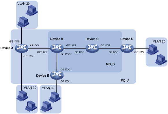
As shown in Figure 1, Device B and Device C reside in the central equipment room of a company. Device A, Device D, and Device E reside in other areas.
· Research and development department users in VLAN 20 access the enterprise network through Device A and Device D.
· Marketing department users in VLAN 30 access the enterprise network through Device A and Device E.
Configure CFD to verify and locate link faults.
Analysis
To accurately locate link faults, assign the enterprise network to MD_A (level 5) and the central equipment room network to MD_B (level 3). MD_A nests MD_B.
To effectively implement CFD, assign MAs based on the VLANs of service traffic:
· Assign VLAN 20 in MD_A to MA_A_1.
· Assign VLAN 30 in MD_A to MA_A_2.
· Assign VLAN 20 in MD_B to MA_B_1.
· Assign VLAN 30 in MD_B to MA_A_2.
To verify link connectivity, configure MEPs on the interfaces located at the boundary of MAs, for example, MA_B_1:
· Configure MEPs on interface GE1/0/1 of Device B and Device D to allow CFD packets from VLAN 20 to pass through the following interfaces:
¡ GE1/0/1 and GE1/0/2 of Device B.
¡ GE1/0/1 and GE1/0/2 of Device C.
¡ GE1/0/1 of Device D.
· Configure GE1/0/1 of Device B as an inward-facing MEP because CFD packets are forwarded through other interfaces on the device.
· Configure GE1/0/1 of Device D as an outward-facing MEP because CFD packets are forwarded through the interface.
To accurately locate link faults between Device B and Device D, configure the default MIP generation rule on Device C.
To detect connectivity among MEPs, configure CC on the MEPs.
To verify link faults detected through CC, use LB. To trace faulty paths or locate link faults, use LT after the status information of the entire network is obtained.
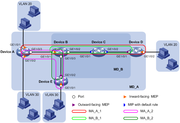
Figure 2 shows a CFD configuration diagram based on the previous analysis.
Figure 2 CFD configuration diagram
Applicable hardware and software versions
The following matrix shows the hardware and software versions to which this configuration example is applicable:
|
Hardware |
Software version |
|
S6520XE-HI switch series |
Supported in Release 11xx |
|
S5560X-EI switch series |
Supported in Release 111x |
|
S5500V2-EI switch series |
Supported in Release 111x |
|
MS4520V2-30F switch |
Supported in Release 111x |
|
S5560S-EI switch series S5560S-SI switch series |
Supported in Release 612x |
|
S5130S-HI switch series S5130S-EI switch series S5130S-SI switch series S5130S-LI switch series |
Supported in Release 612x |
|
S5120V2-SI switch series S5120V2-LI switch series |
Supported in Release 612x |
|
S3100V3-EI switch series S3100V3-SI switch series |
Supported in Release 612x |
|
S5110V2 switch series |
Supported in Release 612x |
|
S5110V2-SI switch series |
Supported in Release 612x |
|
S5000V3-EI switch series |
Supported in Release 612x |
|
S5000E-X switch series |
Supported in Release 612x |
|
WAS6000 switch series |
Supported in Release 612x |
|
E128C switch E152C switch E500C switch series E500D switch series |
Supported in Release 612x |
|
MS4520V2 switch series (except the MS4520V2-30F switch) |
Supported in Release 612x |
|
MS4320V2 switch series MS4300V2 switch series MS4320 switch series MS4200 switch series |
Supported in Release 612x |
|
WS5850-WiNet switch series |
Supported in Release 612x |
|
WS5820-WiNet switch series WS5810-WiNet switch series |
Supported in Release 612x |
Restrictions and guidelines
When you configure CFD, follow these restrictions and guidelines:
· You cannot create a MEP if the MEP ID is not included in the MEP list of the service instance.
· You can configure multiple MAs in an MD as needed. An MA serves only one VLAN.
· Configure the same CCM interval field value for all MEPs in the same MA. In this example, the MEPs use the default CCM interval field value.
Procedures
Enabling CFD
# Enable CFD on Device A.
<DeviceA> system-view
[DeviceA] cfd enable
# Enable CFD on Device B through Device E. (Details not shown.)
Creating VLANs and assigning interfaces to the VLANs
1. Configure Device A:
[DeviceA] vlan 20
[DeviceA-vlan20] quit
[DeviceA] vlan 30
[DeviceA-vlan30] quit
[DeviceA] interface gigabitethernet 1/0/1
[DeviceA-GigabitEthernet1/0/1] port access vlan 20
[DeviceA-GigabitEthernet1/0/1] quit
[DeviceA] interface gigabitethernet 1/0/2
[DeviceA-GigabitEthernet1/0/2] port access vlan 30
[DeviceA-GigabitEthernet1/0/2] quit
[DeviceA] interface gigabitethernet 1/0/3
[DeviceA-GigabitEthernet1/0/3] port link-type trunk
[DeviceA-GigabitEthernet1/0/3] port trunk permit vlan 20 30
[DeviceA-GigabitEthernet1/0/3] quit
2. Configure Device B:
[DeviceB] vlan 20
[DeviceB-vlan20] quit
[DeviceB] vlan 30
[DeviceB-vlan30] quit
[DeviceB] interface gigabitethernet 1/0/1
[DeviceB-GigabitEthernet1/0/1] port link-type trunk
[DeviceB-GigabitEthernet1/0/1] port trunk permit vlan 20 30
[DeviceB-GigabitEthernet1/0/1] quit
[DeviceB] interface gigabitethernet 1/0/2
[DeviceB-GigabitEthernet1/0/2] port link-type trunk
[DeviceB-GigabitEthernet1/0/2] port trunk permit vlan 20
[DeviceB-GigabitEthernet1/0/2] quit
[DeviceB] interface gigabitethernet 1/0/3
[DeviceB-GigabitEthernet1/0/3] port link-type trunk
[DeviceB-GigabitEthernet1/0/3] port trunk permit vlan 30
[DeviceB-GigabitEthernet1/0/3] quit
3. Configure Device C:
[DeviceC] vlan 20
[DeviceC-vlan20] quit
[DeviceC] interface gigabitethernet 1/0/1
[DeviceC-GigabitEthernet1/0/1] port link-type trunk
[DeviceC-GigabitEthernet1/0/1] port trunk permit vlan 20
[DeviceC-GigabitEthernet1/0/1] quit
[DeviceC] interface gigabitethernet 1/0/2
[DeviceC-GigabitEthernet1/0/2] port link-type trunk
[DeviceC-GigabitEthernet1/0/2] port trunk permit vlan 20
[DeviceC-GigabitEthernet1/0/2] quit
4. Configure Device D:
[DeviceD] vlan 20
[DeviceD-vlan20] quit
[DeviceD] interface gigabitethernet 1/0/1
[DeviceD-GigabitEthernet1/0/1] port link-type trunk
[DeviceD-GigabitEthernet1/0/1] port trunk permit vlan 20
[DeviceD-GigabitEthernet1/0/1] quit
[DeviceD] interface gigabitethernet 1/0/2
[DeviceD-GigabitEthernet1/0/2] port access vlan 20
[DeviceD-GigabitEthernet1/0/2] quit
5. Configure Device E:
[DeviceE] vlan 30
[DeviceE-vlan30] quit
[DeviceE] interface gigabitethernet 1/0/1
[DeviceE-GigabitEthernet1/0/1] port access vlan 30
[DeviceE-GigabitEthernet1/0/1] quit
[DeviceE] interface gigabitethernet 1/0/2
[DeviceE-GigabitEthernet1/0/2] port link-type trunk
[DeviceE-GigabitEthernet1/0/2] port trunk permit vlan 30
[DeviceE-GigabitEthernet1/0/2] quit
Configuring service instances
Based on the MAs to which the MEPs belong, perform the configurations as described in the following table:
|
Device |
MD |
MD level |
MA |
VLAN |
Service instance |
|
|
Device A |
MD_A |
5 |
MA_A_1 |
20 |
1 |
|
|
MA_A_2 |
30 |
2 |
||||
|
Device B |
MD_B |
3 |
MA_B_1 |
20 |
3 |
|
|
MA_B_2 |
30 |
4 |
||||
|
Device C |
MD_B |
3 |
MA_B_1 |
20 |
3 |
|
|
Device D |
MD_A |
5 |
MA_A_1 |
20 |
1 |
|
|
MD_B |
3 |
MA_B_1 |
20 |
3 |
||
|
Device E |
MD_A |
5 |
MA_A_2 |
30 |
2 |
|
|
MD_B |
3 |
MA_B_2 |
30 |
4 |
||
1. Configure Device A:
# Create MD_A (level 5).
[DeviceA] cfd md MD_A level 5
# Create service instance 1, in which the MA named MA_A_1 serves VLAN 20.
[DeviceA] cfd service-instance 1 ma-id string MA_A_1 md MD_A vlan 20
# Create service instance 2, in which the MA named MA_A_2 serves VLAN 30.
[DeviceA] cfd service-instance 2 ma-id string MA_A_2 md MD_A vlan 30
Configure Device B through Device E in the same way Device A is configured.
2. Configure Device B:
[DeviceB] cfd md MD_B level 3
[DeviceB] cfd service-instance 3 ma-id string MA_B_1 md MD_B vlan 20
[DeviceB] cfd service-instance 4 ma-id string MA_B_2 md MD_B vlan 30
3. Configure Device C:
[DeviceC] cfd md MD_B level 3
[DeviceC] cfd service-instance 3 ma-id string MA_B_1 md MD_B vlan 20
4. Configure Device D:
[DeviceD] cfd md MD_A level 5
[DeviceD] cfd service-instance 1 ma-id string MA_A_1 md MD_A vlan 20
[DeviceD] cfd md MD_B level 3
[DeviceD] cfd service-instance 3 ma-id string MA_B_1 md MD_B vlan 20
5. Configure Device E:
[DeviceE] cfd service-instance 2 ma-id string MA_A_2 md MD_A vlan 30
[DeviceE] cfd md MD_B level 3
[DeviceE] cfd service-instance 4 ma-id string MA_B_2 md MD_B vlan 30
Configuring MEPs
Assign MEP IDs as described in the following table:
|
Service instance |
Device |
Interface |
MEP ID |
MEP type |
|
1 |
Device A |
GigabitEthernet 1/0/1 |
1001 |
Inward-facing MEP |
|
Device D |
GigabitEthernet 1/0/2 |
1002 |
Inward-facing MEP |
|
|
2 |
Device A |
GigabitEthernet 1/0/2 |
2001 |
Inward-facing MEP |
|
Device E |
GigabitEthernet 1/0/1 |
2002 |
Inward-facing MEP |
|
|
3 |
Device B |
GigabitEthernet 1/0/1 |
3001 |
Inward-facing MEP |
|
Device D |
GigabitEthernet 1/0/1 |
3002 |
Outward-facing MEP |
|
|
4 |
Device B |
GigabitEthernet 1/0/1 |
4001 |
Inward-facing MEP |
|
Device E |
GigabitEthernet 1/0/2 |
4002 |
Outward-facing MEP |
1. Configure Device A:
# Configure a MEP list in service instances 1 and 2.
[DeviceA] cfd meplist 1001 1002 service-instance 1
[DeviceA] cfd meplist 2001 2002 service-instance 2
# Create inward-facing MEP 1001 in service instance 1 on GigabitEthernet 1/0/1.
[DeviceA] interface gigabitethernet 1/0/1
[DeviceA-GigabitEthernet1/0/1] cfd mep 1001 service-instance 1 inbound
[DeviceA-GigabitEthernet1/0/1] quit
# Create inward-facing MEP 2001 in service instance 2 on GigabitEthernet 1/0/2.
[DeviceA] interface gigabitethernet 1/0/2
[DeviceA-GigabitEthernet1/0/2] cfd mep 2001 service-instance 2 inbound
[DeviceA-GigabitEthernet1/0/2] quit
Configure Device B, Device D, and Device E in the same way Device A is configured.
2. Configure Device B:
[DeviceB] cfd meplist 3001 3002 service-instance 3
[DeviceB] cfd meplist 4001 4002 service-instance 4
[DeviceB] interface gigabitethernet 1/0/1
[DeviceB-GigabitEthernet1/0/1] cfd mep 3001 service-instance 3 inbound
[DeviceB-GigabitEthernet1/0/1] cfd mep 4001 service-instance 4 inbound
[DeviceB-GigabitEthernet1/0/1] quit
3. Configure Device D:
[DeviceD] cfd meplist 1001 1002 service-instance 1
[DeviceD] cfd meplist 3001 3002 service-instance 3
[DeviceD] interface gigabitethernet 1/0/2
[DeviceD-GigabitEthernet1/0/2] cfd mep 1002 service-instance 1 inbound
[DeviceD-GigabitEthernet1/0/2] quit
[DeviceD] interface gigabitethernet 1/0/1
[DeviceD-GigabitEthernet1/0/1] cfd mep 3002 service-instance 3 outbound
[DeviceD-GigabitEthernet1/0/1] quit
4. Configure Device E:
[DeviceE] cfd meplist 2001 2002 service-instance 2
[DeviceE] cfd meplist 4001 4002 service-instance 4
[DeviceE] interface gigabitethernet 1/0/1
[DeviceE-GigabitEthernet1/0/1] cfd mep 2002 service-instance 2 inbound
[DeviceE-GigabitEthernet1/0/1] quit
[DeviceE] interface gigabitethernet 1/0/2
[DeviceE-GigabitEthernet1/0/2] cfd mep 4002 service-instance 4 outbound
[DeviceE-GigabitEthernet1/0/2] quit
Configuring a MIP generation rule
# Configure the MIP generation rule in service instance 3 on Device C as default.
[DeviceC] cfd mip-rule default service-instance 3
Configuring CC on MEPs
1. Configure Device A:
# Enable the sending of CCM frames for MEP 1001 in service instance 1 on GigabitEthernet 1/0/1.
[DeviceA] interface gigabitethernet 1/0/1
[DeviceA-GigabitEthernet1/0/1] cfd cc service-instance 1 mep 1001 enable
[DeviceA-GigabitEthernet1/0/1] quit
# Enable the sending of CCM frames for MEP 2001 in service instance 2 on GigabitEthernet 1/0/2.
[DeviceA] interface gigabitethernet 1/0/2
[DeviceA-GigabitEthernet1/0/2] cfd cc service-instance 2 mep 2001 enable
[DeviceA-GigabitEthernet1/0/2] quit
Configure Device B, Device D, and Device E in the same way Device A is configured.
2. Configure Device B:
[DeviceB] interface gigabitethernet 1/0/1
[DeviceB-GigabitEthernet1/0/1] cfd cc service-instance 3 mep 3001 enable
[DeviceB-GigabitEthernet1/0/1] cfd cc service-instance 4 mep 4001 enable
[DeviceB-GigabitEthernet1/0/1] quit
3. Configure Device D:
[DeviceD] interface gigabitethernet 1/0/1
[DeviceD-GigabitEthernet1/0/1] cfd cc service-instance 3 mep 3002 enable
[DeviceD-GigabitEthernet1/0/1] quit
[DeviceD] interface gigabitethernet 1/0/2
[DeviceD-GigabitEthernet1/0/2] cfd cc service-instance 1 mep 1002 enable
[DeviceD-GigabitEthernet1/0/2] quit
4. Configure Device E:
[DeviceE] interface gigabitethernet 1/0/1
[DeviceE-GigabitEthernet1/0/1] cfd cc service-instance 2 mep 2002 enable
[DeviceE-GigabitEthernet1/0/1] quit
[DeviceE] interface gigabitethernet 1/0/2
[DeviceE-GigabitEthernet1/0/2] cfd cc service-instance 4 mep 4002 enable
[DeviceE-GigabitEthernet1/0/2] quit
Verifying the configuration
In this example, the MAC addresses of Device A through Device E are 0010-FC01-6511, 0010-FC02-6512, 0010-FC03-6513, 0010-FC04-6514, and 0010-FC05-6515, respectively.
1. Verify the configuration when the network is operating correctly:
# Display information about remote MEP 1001 in service instance 1 on Device A.
[DeviceA] display cfd remote-mep service-instance 1 mep 1001
MEP ID MAC address State Time MAC status
1002 0010-fc04-6514 OK 2018/07/26 12:54:52 UP
The output shows that the remote MEP is operating correctly.
# Enable LB on Device A to verify the status of the link between MEP 1001 and MEP 1002 in service instance 1.
[DeviceA] cfd loopback service-instance 1 mep 1001 target-mep 1002
Loopback to MEP 1002 with the sequence number start from 1001-43404:
Reply from 0010-fc04-6514: sequence number=1001-43404 Time=5ms
Reply from 0010-fc04-6514: sequence number=1001-43405 Time=5ms
Reply from 0010-fc04-6514: sequence number=1001-43406 Time=5ms
Reply from 0010-fc04-6514: sequence number=1001-43407 Time=5ms
Reply from 0010-fc04-6514: sequence number=1001-43408 Time=5ms
Sent: 5 Received: 5 Lost: 0
The output shows that no link fault occurs on the link between MEP 1001 and MEP 1002 in service instance 1.
2. Verify the configuration when a link fault occurs:
# Display information about remote MEP 1001 in service instance 1 on Device A.
[DeviceA] display cfd remote-mep service-instance 1 mep 1001
MEP ID MAC address State Time MAC status
1002 0010-fc04-6514 FAILED 2018/07/26 13:01:52 DOWN
The output shows that the remote MEP is operating incorrectly.
# Enable LB on Device A to verify the status of the link between MEP 1001 and MEP 1002 in service instance 1.
[DeviceA] cfd loopback service-instance 1 mep 1001 target-mep 1002
Loopback to MEP 1002 with the sequence number start from 1001-43904:
Sent: 5 Received: 0 Lost: 5
The output shows that a link fault occurs on the link between MEP 1001 and MEP 1002 in service instance 1.
# Identify the path between MEP 3001 and MEP 3002 in service instance 3 on Device B.
[DeviceB] cfd linktrace service-instance 3 mep 3001 target-mep 3002
Linktrace to MEP 3002 with the sequence number 3001-43862:
MAC Address TTL Last Mac Relay Action
0010-fc03-6513 63 0010-fc02-6512 MPDB
The output shows that MEP 3001 receives only the LTR messages from the MIP. No LTR messages are sent from MEP 3002 (GigabitEthernet 1/0/1 on Device D). The link between Device C and Device D fails, and you do not need to troubleshoot the network outside MD_B.
Configuration files
· Device A:
cfd enable
cfd md MD_A index 1 level 5
cfd service-instance 1 ma-id string MA_A_1 ma-index 1 md MD_A vlan 20
cfd meplist 1001 to 1002 service-instance 1
cfd service-instance 2 ma-id string MA_A_2 ma-index 1 md MD_A vlan 30
cfd meplist 2001 to 2002 service-instance 2
#
vlan 20
#
vlan 30
#
interface GigabitEthernet1/0/1
port link-mode bridge
port access vlan 20
cfd mep 1001 service-instance 1 inbound
cfd cc service-instance 1 mep 1001 enable
#
interface GigabitEthernet1/0/2
port link-mode bridge
port access vlan 30
cfd mep 2001 service-instance 2 inbound
cfd cc service-instance 2 mep 2001 enable
#
interface GigabitEthernet1/0/3
port link-mode bridge
port link-type trunk
port trunk permit vlan 20 30
· Device B:
#
cfd enable
cfd md MD_B index 1 level 3
cfd service-instance 3 ma-id string MA_B_1 ma-index 1 md MD_B vlan 20
cfd meplist 3001 to 3002 service-instance 3
cfd service-instance 4 ma-id string MA_B_2 ma-index 2 md MD_B vlan 30
cfd meplist 4001 to 4002 service-instance 4
#
vlan 20
#
vlan 30
#
interface GigabitEthernet1/0/1
port link-mode bridge
port link-type trunk
port trunk permit vlan 20 30
cfd mep 3001 service-instance 3 inbound
cfd cc service-instance 3 mep 3001 enable
cfd mep 4001 service-instance 4 inbound
cfd cc service-instance 4 mep 4001 enable
#
interface GigabitEthernet1/0/2
port link-mode bridge
port link-type trunk
port trunk permit vlan 20
#
interface GigabitEthernet1/0/3
port link-mode bridge
port link-type trunk
port trunk permit vlan 30
· Device C:
#
cfd enable
cfd md MD_B index 1 level 3
cfd service-instance 3 ma-id string MA_B_1 ma-index 1 md MD_B vlan 20
cfd mip-rule default service-instance 3
#
vlan 20
#
interface GigabitEthernet1/0/1
port link-mode bridge
port link-type trunk
port trunk permit vlan 20
#
interface GigabitEthernet1/0/2
port link-mode bridge
port link-type trunk
port trunk permit vlan 20
· Device D:
cfd enable
cfd md MD_A index 1 level 5
cfd md MD_B index 2 level 3
cfd service-instance 1 ma-id string MA_A_1 ma-index 1 md MD_A vlan 20
cfd meplist 1001 to 1002 service-instance 1
cfd service-instance 3 ma-id string MA_B_1 ma-index 1 md MD_B vlan 20
cfd meplist 3001 to 3002 service-instance 3
#
vlan 20
#
interface GigabitEthernet1/0/1
port link-mode bridge
port link-type trunk
port trunk permit vlan 20
cfd mep 3002 service-instance 3 outbound
cfd cc service-instance 3 mep 3002 enable
#
interface GigabitEthernet1/0/2
port link-mode bridge
port access vlan 20
cfd mep 1002 service-instance 1 inbound
cfd cc service-instance 1 mep 1002 enable
· Device E:
#
cfd enable
cfd md MD_A index 1 level 5
cfd md MD_B index 2 level 3
cfd service-instance 2 ma-id string MA_A_2 ma-index 1 md MD_A vlan 30
cfd meplist 2001 to 2002 service-instance 2
cfd service-instance 4 ma-id string MA_B_2 ma-index 2 md MD_B vlan 30
cfd meplist 4001 to 4002 service-instance 4
#
vlan 30
#
interface GigabitEthernet1/0/1
port link-mode bridge
port access vlan 30
cfd mep 2002 service-instance 2 inbound
cfd cc service-instance 2 mep 2002 enable
#
interface GigabitEthernet1/0/2
port link-mode bridge
port link-type trunk
port trunk permit vlan 30
cfd mep 4002 service-instance 4 outbound
cfd cc service-instance 4 mep 4002 enable