- Table of Contents
-
- H3C Fixed Port Campus Switches Configuration Examples-B70D022-6W100
- 01-Login Management Configuration Examples
- 02-RBAC Configuration Examples
- 03-Software Upgrade Examples
- 04-ISSU Configuration Examples
- 05-Software Patching Examples
- 06-Ethernet Link Aggregation Configuration Examples
- 07-Port Isolation Configuration Examples
- 08-Spanning Tree Configuration Examples
- 09-VLAN Configuration Examples
- 10-VLAN Tagging Configuration Examples
- 11-DHCP Snooping Configuration Examples
- 12-Cross-Subnet Dynamic IP Address Allocation Configuration Examples
- 13-IPv6 over IPv4 Manual Tunneling with OSPFv3 Configuration Examples
- 14-ISATAP Tunnel and 6to4 Tunnel Configuration Examples
- 15-GRE Tunnel Configuration Examples
- 16-GRE with OSPF Configuration Examples
- 17-OSPF Configuration Examples
- 18-IS-IS Configuration Examples
- 19-BGP Configuration Examples
- 20-Policy-Based Routing Configuration Examples
- 21-OSPFv3 Configuration Examples
- 22-IPv6 IS-IS Configuration Examples
- 23-Routing Policy Configuration Examples
- 24-IGMP Snooping Configuration Examples
- 25-IGMP Configuration Examples
- 26-BIDIR-PIM Configuration Examples
- 27-Multicast VPN Configuration Examples
- 28-MLD Snooping Configuration Examples
- 29-IPv6 Multicast VLAN Configuration Examples
- 30-Basic MPLS Configuration Examples
- 31-MPLS L3VPN Configuration Examples
- 32-ACL Configuration Examples
- 33-Control Plane-Based QoS Policy Configuration Examples
- 34-Traffic Policing Configuration Examples
- 35-GTS and Rate Limiting Configuration Examples
- 36-Priority Mapping and Queue Scheduling Configuration Examples
- 37-Traffic Filtering Configuration Examples
- 38-AAA Configuration Examples
- 39-Port Security Configuration Examples
- 40-Portal Configuration Examples
- 41-SSH Configuration Examples
- 42-IP Source Guard Configuration Examples
- 43-Ethernet OAM Configuration Examples
- 44-CFD Configuration Examples
- 45-DLDP Configuration Examples
- 46-VRRP Configuration Examples
- 47-BFD Configuration Examples
- 48-NTP Configuration Examples
- 49-SNMP Configuration Examples
- 50-NQA Configuration Examples
- 51-Mirroring Configuration Examples
- 52-sFlow Configuration Examples
- 53-OpenFlow Configuration Examples
- 54-MAC Address Table Configuration Examples
- 55-Static Multicast MAC Address Entry Configuration Examples
- 56-IP Unnumbered Configuration Examples
- 57-MVRP Configuration Examples
- 58-MCE Configuration Examples
- 59-Congestion Avoidance and Queue Scheduling Configuration Examples
- 60-Attack Protection Configuration Examples
- 61-Smart Link Configuration Examples
- 62-RRPP Configuration Examples
- 63-BGP Route Selection Configuration Examples
- 64-IS-IS Route Summarization Configuration Examples
- 65-IRF Configuration Examples
- 66-MPLS TE Configuration Examples
- 67-VXLAN Configuration Examples
- 68-VCF Fabric Configuration Examples
- Related Documents
-
| Title | Size | Download |
|---|---|---|
| 30-Basic MPLS Configuration Examples | 125.77 KB |
Example: Configuring static LSPs
Applicable hardware and software versions
Applicable hardware and software versions
Introduction
This document provides static LSP and LDP LSP configuration examples.
The following table shows the differences between a static LSP and an LDP LSP:
|
LSP type |
Establishment |
Feature |
Application scenario |
|
Static LSP |
You establish a static LSP by specifying the incoming and outgoing labels on ingress, transit, and egress nodes of the forwarding path. |
· Consumes fewer resources. · Cannot automatically adapt to network topology changes. |
Small and stable networks with simple topologies. |
|
LDP LSP |
You establish an LDP LSP by configuring MPLS LDP. LDP classifies FECs, distributes FEC-label mappings, and establishes and maintains LSPs. |
· Consumes more resources. · Automatically adapts to network topology changes. |
Large and unstable networks with complicated topologies. |
Prerequisites
This document is not restricted to specific software or hardware versions.
The configuration examples in this document were created and verified in a lab environment, and all the devices were started with the factory default configuration. When you are working on a live network, make sure you understand the potential impact of every command on your network.
This document assumes that you have basic knowledge of MPLS and LDP.
Example: Configuring static LSPs
Network configuration
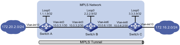
As shown in Figure 1, establish static LSPs between Switch A and Switch C to allow communication between subnets 172.20.2.0/24 and 172.16.2.0/24 over the MPLS network.
Analysis
LSPs are unidirectional. To ensure that data can be bidirectionally forwarded, configure an LSP for each direction of the data forwarding path, and specify the ingress, transit, and egress nodes for each LSP.
To direct traffic to an LSP for MPLS forwarding, make sure the ingress node has a route to the FEC destination of the LSP. This example uses a static route. Route configuration is not needed on the transit and egress nodes.
Applicable hardware and software versions
The following matrix shows the hardware and software versions to which this configuration example is applicable:
|
Hardware |
Software version |
|
S6520XE-HI switch series |
Supported in Release 11xx |
|
S5560X-EI switch series |
Not supported |
|
S5500V2-EI switch series |
Not supported |
|
MS4520V2-30F switch |
Not supported |
|
S5560S-EI switch series S5560S-SI switch series |
Not supported |
|
S5130S-HI switch series S5130S-EI switch series S5130S-SI switch series S5130S-LI switch series |
Not supported |
|
S5120V2-SI switch series S5120V2-LI switch series |
Not supported |
|
S3100V3-EI switch series S3100V3-SI switch series |
Not supported |
|
S5110V2 switch series |
Not supported |
|
S5110V2-SI switch series |
Not supported |
|
S5000V3-EI switch series |
Not supported |
|
S5000E-X switch series |
Not supported |
|
WAS6000 switch series |
Not supported |
|
E128C switch E152C switch E500C switch series E500D switch series |
Not supported |
|
MS4520V2 switch series (except the MS4520V2-30F switch) |
Not supported |
|
MS4320V2 switch series MS4300V2 switch series MS4320 switch series MS4200 switch series |
Not supported |
|
WS5850-WiNet switch series |
Not supported |
|
WS5820-WiNet switch series WS5810-WiNet switch series |
Not supported |
Restrictions and guidelines
When you configure a static LSP, follow these restrictions and guidelines:
· Make sure the outgoing label specified on an LSR is the same as the incoming label specified on the directly connected downstream LSR.
· If you configure a static IP route for the LSP, specify the same next hop or outgoing interface for the static route and the static LSP.
· On the ingress or transit node of the static LSP, do not specify the public address of a local interface as the next hop address of the static LSP.
· MPLS adds a label or multiple labels to packets. After MPLS is enabled on a VLAN interface, configure jumboframe support on the ports in the VLAN to avoid MPLS packet dropping when the packet size exceeds the interface MTU.
Procedures
1. Configure IP addresses and masks for interfaces, including the loopback interfaces, as shown in Figure 1. (Details not shown.)
2. Configure a static route to the destination address of each LSP:
# Configure a static route to the FEC destination of the LSP from Switch A to Switch C.
<SwitchA> system-view
[SwitchA] ip route-static 172.16.2.1 24 10.0.3.2
# Configure a static route to the FEC destination of the LSP from Switch C to Switch A.
<SwitchC> system-view
[SwitchC] ip route-static 172.20.2.1 24 10.0.6.1
# Verify that the static route has been created on the ingress nodes, for example, on Switch A.
[SwitchA] display ip routing-table
Destinations : 13 Routes : 13
Destination/Mask Proto Pre Cost NextHop Interface
0.0.0.0/32 Direct 0 0 127.0.0.1 InLoop0
172.16.2.1/24 Static 60 0 10.0.3.2 Vlan3
10.0.3.0/24 Direct 0 0 10.0.3.1 Vlan3
10.0.3.0/32 Direct 0 0 10.0.3.1 Vlan3
10.0.3.1/32 Direct 0 0 127.0.0.1 InLoop0
1.1.1.9/32 Direct 0 0 127.0.0.1 InLoop0
127.0.0.0/8 Direct 0 0 127.0.0.1 InLoop0
127.0.0.0/32 Direct 0 0 127.0.0.1 InLoop0
127.0.0.1/32 Direct 0 0 127.0.0.1 InLoop0
127.255.255.255/32 Direct 0 0 127.0.0.1 InLoop0
224.0.0.0/4 Direct 0 0 0.0.0.0 NULL0
224.0.0.0/24 Direct 0 0 0.0.0.0 NULL0
255.255.255.255/32 Direct 0 0 127.0.0.1 InLoop0
3. Configure basic MPLS on the switches:
# Configure Switch A.
[SwitchA] mpls lsr-id 1.1.1.9
[SwitchA] interface vlan-interface 3
[SwitchA-Vlan-interface3] mpls enable
[SwitchA-Vlan-interface3] quit
# Configure Switch B.
[SwitchB] mpls lsr-id 2.2.2.9
[SwitchB] interface vlan-interface 3
[SwitchB-Vlan-interface3] mpls enable
[SwitchB-Vlan-interface3] quit
[SwitchB] interface vlan-interface 6
[SwitchB-Vlan-interface6] mpls enable
[SwitchB-Vlan-interface6] quit
# Configure Switch C.
[SwitchC] mpls lsr-id 3.3.3.9
[SwitchC] interface vlan-interface 6
[SwitchC-Vlan-interface6] mpls enable
[SwitchC-Vlan-interface6] quit
4. Configure a static LSP from Switch A to Switch C:
# Configure the ingress node Switch A. Specify the LSP name as AtoC, destination address as 172.16.2.1/24, next hop as 10.0.3.2, and outgoing label as 30.
[SwitchA] static-lsp ingress AtoC destination 172.16.2.1 24 nexthop 10.0.3.2 out-label 30
# Configure the transit node Switch B. Specify the LSP name as AtoC, incoming label as 30, next hop as 10.0.6.2, and outgoing label as 50.
[SwitchB] static-lsp transit AtoC in-label 30 nexthop 10.0.6.2 out-label 50
# Configure the egress node Switch C. Specify the LSP name as AtoC and incoming label as 50.
[SwitchC] static-lsp egress AtoC in-label 50
5. Configure a static LSP from Switch C to Switch A:
# Configure the ingress node Switch C. Specify the LSP name as CtoA, destination address as 172.20.2.1/24, next hop as 10.0.6.1, and outgoing label as 40.
[SwitchC] static-lsp ingress CtoA destination 172.20.2.1 24 nexthop 10.0.6.1 out-label 40
# Configure the transit node Switch B. Specify the LSP name as CtoA, incoming label as 40, next hop as 10.0.3.1, and outgoing label as 70.
[SwitchB] static-lsp transit CtoA in-label 40 nexthop 10.0.3.1 out-label 70
# Configure the egress node Switch A. Specify the LSP name as CtoA and incoming label as 70.
[SwitchA] static-lsp egress CtoA in-label 70
Verifying the configuration
# Display static LSP information on switches, for example, on Switch A.
[SwitchA] display mpls static-lsp
Total: 2
Name FEC In/Out Label Nexthop/Out Interface State
AtoC 172.16.2.1/24 NULL/30 10.0.3.2 Up
CtoA -/- 70/NULL - Up
# Test the connectivity of the LSP from Switch A to Switch C.
[SwitchA] ping mpls -a 172.20.2.1 ipv4 172.16.2.0 24
MPLS ping FEC 172.16.2.0/24 with 100 bytes of data:
100 bytes from 10.0.6.2: Sequence=1 time=3 ms
100 bytes from 10.0.6.2: Sequence=2 time=2 ms
100 bytes from 10.0.6.2: Sequence=3 time=2 ms
100 bytes from 10.0.6.2: Sequence=4 time=2 ms
100 bytes from 10.0.6.2: Sequence=5 time=27 ms
--- Ping statistics for FEC 172.16.2.0/24 ---
5 packets transmitted, 5 packets received, 0.0% packet loss
Round-trip min/avg/max = 2/7/27 ms
# Test the connectivity of the LSP from Switch C to Switch A.
[SwitchC] ping mpls -a 172.16.2.1 ipv4 172.20.2.0 24
MPLS ping FEC 172.20.2.0/24 with 100 bytes of data:
100 bytes from 10.0.3.2: Sequence=1 time=3 ms
100 bytes from 10.0.3.2: Sequence=2 time=2 ms
100 bytes from 10.0.3.2: Sequence=3 time=2 ms
100 bytes from 10.0.3.2: Sequence=4 time=2 ms
100 bytes from 10.0.3.2: Sequence=5 time=27 ms
--- Ping statistics for FEC 172.20.2.0/24 ---
5 packets transmitted, 5 packets received, 0.0% packet loss
Round-trip min/avg/max = 2/7/27 ms
Configuration files
· Switch A:
#
mpls lsr-id 1.1.1.9
#
vlan 3
#
vlan 10
#
interface LoopBack0
ip address 1.1.1.9 255.255.255.255
#
interface Vlan-interface3
ip address 10.0.3.1 255.255.255.0
mpls enable
#
interface Vlan-interface10
ip address 172.20.2.1 255.255.255.0
#
ip route-static 172.16.2.1 255.255.255.0 10.0.3.2
#
static-lsp ingress AtoC destination 172.16.2.1 24 nexthop 10.0.3.2 out-label 30
static-lsp egress CtoA in-label 70
#
· Switch B:
#
mpls lsr-id 2.2.2.9
#
vlan 3
#
vlan 6
#
interface LoopBack0
ip address 2.2.2.9 255.255.255.255
#
interface Vlan-interface3
ip address 10.0.3.2 255.255.255.0
mpls enable
#
interface Vlan-interface6
ip address 10.0.6.1 255.255.255.0
mpls enable
#
static-lsp transit AtoC in-label 30 nexthop 10.0.6.2 out-label 50
static-lsp transit CtoA in-label 40 nexthop 10.0.3.1 out-label 70
#
· Switch C:
#
mpls lsr-id 3.3.3.9
#
vlan 6
#
vlan 10
#
interface LoopBack0
ip address 3.3.3.9 255.255.255.255
#
interface Vlan-interface6
ip address 10.0.6.2 255.255.255.0
mpls enable
#
interface Vlan-interface10
ip address 172.16.2.1 255.255.255.0
#
ip route-static 172.20.2.1 255.255.255.0 10.0.6.2
#
static-lsp ingress CtoA destination 172.20.2.1 24 nexthop 10.0.6.1 out-label 40
static-lsp egress AtoC in-label 50
#
Example: Configuring LDP LSPs
Network configuration
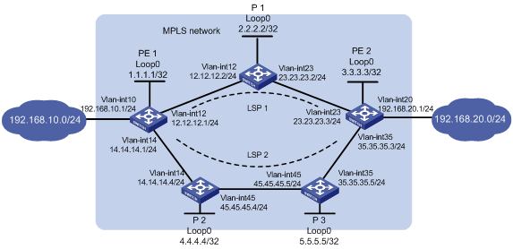
As shown in Figure 2, two paths are available for PE 1 and PE 2 to communicate with each other.
· Configure LDP to establish LSPs between PE 1 and PE 2 to allow communication between subnets 192.168.10.0/24 and 192.168.20.0/24 over the MPLS network.
¡ Use LSP 1 as the primary path.
¡ Use LSP 2 as the backup path, which takes over LSP 1 when LSP 1 fails.
· Configure LDP to establish LSPs only for destinations 1.1.1.1/32, 2.2.2.2/32, 3.3.3.3/32, 4.4.4.4/32, 5.5.5.5/32, 192.168.10.0/24, and 192.168.20.0/24.
Analysis
To establish LDP LSPs, configure a routing protocol to ensure IP connectivity among the devices. This example uses OSPF.
To use LSP 1 as the primary path and LSP 2 as the backup, configure the routes for LSP 1 and LSP 2 as the primary and backup routes, respectively. This example uses OSPF. The OSPF cost of the route for LSP 1 is smaller than that for LSP 2. Therefore, LSP 1 is used when it is available.
To control LSP establishment, configure LSP generation policies on each LSR.
Applicable hardware and software versions
The following matrix shows the hardware and software versions to which this configuration example is applicable:
|
Hardware |
Software version |
|
S6520XE-HI switch series |
Supported in Release 11xx |
|
S5560X-EI switch series |
Not supported |
|
S5500V2-EI switch series |
Not supported |
|
MS4520V2-30F switch |
Not supported |
|
S5560S-EI switch series S5560S-SI switch series |
Not supported |
|
S5130S-HI switch series S5130S-EI switch series S5130S-SI switch series S5130S-LI switch series |
Not supported |
|
S5120V2-SI switch series S5120V2-LI switch series |
Not supported |
|
S3100V3-EI switch series S3100V3-SI switch series |
Not supported |
|
S5110V2 switch series |
Not supported |
|
S5110V2-SI switch series |
Not supported |
|
S5000V3-EI switch series |
Not supported |
|
S5000E-X switch series |
Not supported |
|
WAS6000 switch series |
Not supported |
|
E128C switch E152C switch E500C switch series E500D switch series |
Not supported |
|
MS4520V2 switch series (except the MS4520V2-30F switch) |
Not supported |
|
MS4320V2 switch series MS4300V2 switch series MS4320 switch series MS4200 switch series |
Not supported |
|
WS5850-WiNet switch series |
Not supported |
|
WS5820-WiNet switch series WS5810-WiNet switch series |
Not supported |
Procedures
Before configuring LDP LSPs, make sure STP is disabled or each VLAN has been mapped to an MSTP instance.
1. Configure IP addresses and masks for interfaces, including the loopback interfaces, as shown in Figure 2. (Details not shown.)
2. Configure OSPF on each switch to ensure IP connectivity:
# Configure PE 1.
[PE1] ospf
[PE1-ospf-1] area 0
[PE1-ospf-1-area-0.0.0.0] network 1.1.1.1 0.0.0.0
[PE1-ospf-1-area-0.0.0.0] network 12.12.12.0 0.0.0.255
[PE1-ospf-1-area-0.0.0.0] network 14.14.14.0 0.0.0.255
[PE1-ospf-1-area-0.0.0.0] network 192.168.10.0 0.0.0.255
[PE1-ospf-1-area-0.0.0.0] quit
[PE1-ospf-1] quit
# Configure P 1.
[P1] ospf
[P1-ospf-1] area 0
[P1-ospf-1-area-0.0.0.0] network 2.2.2.2 0.0.0.0
[P1-ospf-1-area-0.0.0.0] network 12.12.12.0 0.0.0.255
[P1-ospf-1-area-0.0.0.0] network 23.23.23.0 0.0.0.255
[P1-ospf-1-area-0.0.0.0] quit
[P1-ospf-1] quit
# Configure P 2.
[P2] ospf
[P2-ospf-1] area 0
[P2-ospf-1-area-0.0.0.0] network 4.4.4.4 0.0.0.0
[P2-ospf-1-area-0.0.0.0] network 14.14.14.0 0.0.0.255
[P2-ospf-1-area-0.0.0.0] network 45.45.45.0 0.0.0.255
[P2-ospf-1-area-0.0.0.0] quit
[P2-ospf-1] quit
# Configure P 3.
[P3] ospf
[P3-ospf-1] area 0
[P3-ospf-1-area-0.0.0.0] network 5.5.5.5 0.0.0.0
[P3-ospf-1-area-0.0.0.0] network 45.45.45.0 0.0.0.255
[P3-ospf-1-area-0.0.0.0] network 35.35.35.0 0.0.0.255
[P3-ospf-1-area-0.0.0.0] quit
[P3-ospf-1] quit
# Configure PE 2.
[PE2] ospf
[PE2-ospf-1] area 0
[PE2-ospf-1-area-0.0.0.0] network 3.3.3.3 0.0.0.0
[PE2-ospf-1-area-0.0.0.0] network 23.23.23.0 0.0.0.255
[PE2-ospf-1-area-0.0.0.0] network 35.35.35.0 0.0.0.255
[PE2-ospf-1-area-0.0.0.0] network 192.168.20.0 0.0.0.255
[PE2-ospf-1-area-0.0.0.0] quit
[PE2-ospf-1] quit
# On each switch, for example, on PE 1, verify that the switches have learned the routes to each other.
[PE1] display ospf routing
OSPF Process 1 with Router ID 1.1.1.1
Routing Table
Topology base (MTID 0)
Routing for network
Destination Cost Type NextHop AdvRouter Area
45.45.45.0/24 2 Transit 14.14.14.4 5.5.5.5 0.0.0.0
35.35.35.0/24 3 Transit 14.14.14.4 5.5.5.5 0.0.0.0
35.35.35.0/24 3 Transit 12.12.12.2 5.5.5.5 0.0.0.0
192.168.10.0/24 1 Stub 192.168.10.1 1.1.1.1 0.0.0.0
5.5.5.5/32 2 Stub 14.14.14.4 5.5.5.5 0.0.0.0
14.14.14.0/24 1 Transit 14.14.14.1 4.4.4.4 0.0.0.0
23.23.23.0/24 2 Transit 12.12.12.2 3.3.3.3 0.0.0.0
4.4.4.4/32 1 Stub 14.14.14.4 4.4.4.4 0.0.0.0
3.3.3.3/32 2 Stub 12.12.12.2 3.3.3.3 0.0.0.0
12.12.12.0/24 1 Transit 12.12.12.1 2.2.2.2 0.0.0.0
2.2.2.2/32 1 Stub 12.12.12.2 2.2.2.2 0.0.0.0
1.1.1.1/32 0 Stub 1.1.1.1 1.1.1.1 0.0.0.0
192.168.20.0/24 3 Stub 12.12.12.2 3.3.3.3 0.0.0.0
# On each switch, for example, on PE 1, verify that OSPF neighbor relationships in Full state have been established between PE 1, P devices, and PE 2.
[PE1] display ospf peer verbose
OSPF Process 1 with Router ID 1.1.1.1
Neighbors
Area 0.0.0.0 interface 14.14.14.1(Vlan-interface14)'s neighbors
Router ID: 4.4.4.4 Address: 14.14.14.4 GR state: Normal
State: Full Mode: Nbr is master Priority: 1
DR: 14.14.14.4 BDR: 14.14.14.1 MTU: 0
Options is 0x42 (-|O|-|-|-|-|E|-)
Dead timer due in 40 sec
Neighbor is up for 00:03:30
Authentication Sequence: [ 0 ]
Neighbor state change count: 6
BFD status: Disabled
Neighbors
Area 0.0.0.0 interface 12.12.12.1(Vlan-interface12)'s neighbors
Router ID: 2.2.2.2 Address: 12.12.12.2 GR state: Normal
State: Full Mode: Nbr is master Priority: 1
DR: 12.12.12.2 BDR: 12.12.12.1 MTU: 0
Options is 0x42 (-|O|-|-|-|-|E|-)
Dead timer due in 36 sec
Neighbor is up for 00:03:24
Authentication Sequence: [ 0 ]
Neighbor state change count: 6
BFD status: Disabled
Last Neighbor Down Event:
Router ID: 4.4.4.4
Local Address: 14.14.14.1
Remote Address: 14.14.14.4
Time: May 14 09:07:19 2014
Reason: Reset ospf command was performed
3. Configure basic MPLS and MPLS LDP:
# Configure PE 1.
[PE1] mpls lsr-id 1.1.1.1
[PE1] mpls ldp
[PE1-ldp] quit
[PE1] interface vlan-interface 12
[PE1-Vlan-interface12] mpls enable
[PE1-Vlan-interface12] mpls ldp enable
[PE1-Vlan-interface12] quit
[PE1] interface vlan-interface 14
[PE1-Vlan-interface14] mpls enable
[PE1-Vlan-interface14] mpls ldp enable
[PE1-Vlan-interface14] quit
# Configure P 1.
[P1] mpls lsr-id 2.2.2.2
[P1] mpls ldp
[P1-ldp] quit
[P1] interface vlan-interface 12
[P1-Vlan-interface12] mpls enable
[P1-Vlan-interface12] mpls ldp enable
[P1-Vlan-interface12] quit
[P1] interface vlan-interface 23
[P1-Vlan-interface23] mpls enable
[P1-Vlan-interface23] mpls ldp enable
[P1-Vlan-interface23] quit
# Configure P 2.
[P2] mpls lsr-id 4.4.4.4
[P2] mpls ldp
[P2-ldp] quit
[P2] interface vlan-interface 14
[P2-Vlan-interface14] mpls enable
[P2-Vlan-interface14] mpls ldp enable
[P2-Vlan-interface14] quit
[P2] interface vlan-interface 45
[P2-Vlan-interface45] mpls enable
[P2-Vlan-interface45] mpls ldp enable
[P2-Vlan-interface45] quit
# Configure P 3.
[P3] mpls lsr-id 5.5.5.5
[P3] mpls ldp
[P3-ldp] quit
[P3] interface vlan-interface 45
[P3-Vlan-interface45] mpls enable
[P3-Vlan-interface45] mpls ldp enable
[P3-Vlan-interface45] quit
[P3] interface vlan-interface 35
[P3-Vlan-interface35] mpls enable
[P3-Vlan-interface35] mpls ldp enable
[P3-Vlan-interface35] quit
# Configure PE 2.
[PE2] mpls lsr-id 3.3.3.3
[PE2] mpls ldp
[PE2-ldp] quit
[PE2] interface vlan-interface 23
[PE2-Vlan-interface23] mpls enable
[PE2-Vlan-interface23] mpls ldp enable
[PE2-Vlan-interface23] quit
[PE2] interface vlan-interface 35
[PE2-Vlan-interface35] mpls enable
[PE2-Vlan-interface35] mpls ldp enable
[PE2-Vlan-interface35] quit
# On each switch, for example, on PE 1, verify that LDP sessions in Operational state have been established between PE 1, P devices, and PE 2.
[PE1 display mpls ldp peer
Total number of peers: 2
Peer LDP ID State Role GR MD5 KA Sent/Rcvd
2.2.2.2:0 Operational Passive Off Off 55/55
4.4.4.4:0 Operational Passive Off Off 6/6
4. Configure LSP generation policies:
# On PE 1, create IP prefix list PE1, and configure LDP to use only the routes permitted by the prefix list to establish LSPs.
[PE1] ip prefix-list PE1 index 10 permit 1.1.1.1 32
[PE1] ip prefix-list PE1 index 20 permit 2.2.2.2 32
[PE1] ip prefix-list PE1 index 30 permit 3.3.3.3 32
[PE1] ip prefix-list PE1 index 40 permit 4.4.4.4 32
[PE1] ip prefix-list PE1 index 50 permit 5.5.5.5 32
[PE1] ip prefix-list PE1 index 60 permit 192.168.10.0 24
[PE1] ip prefix-list PE1 index 70 permit 192.168.20.0 24
[PE1] mpls ldp
[PE1-ldp] lsp-trigger prefix-list PE1
[PE1-ldp] quit
# On P 1, create IP prefix list P1, and configure LDP to use only the routes permitted by the prefix list to establish LSPs.
[P1] ip prefix-list P1 index 10 permit 1.1.1.1 32
[P1] ip prefix-list P1 index 20 permit 2.2.2.2 32
[P1] ip prefix-list P1 index 30 permit 3.3.3.3 32
[P1] ip prefix-list P1 index 40 permit 4.4.4.4 32
[P1] ip prefix-list P1 index 50 permit 5.5.5.5 32
[P1] ip prefix-list P1 index 60 permit 192.168.10.0 24
[P1] ip prefix-list P1 index 70 permit 192.168.20.0 24
[P1] mpls ldp
[P1-ldp] lsp-trigger prefix-list P1
[P1-ldp] quit
# On P 2, create IP prefix list P2, and configure LDP to use only the routes permitted by the prefix list to establish LSPs.
[P2] ip prefix-list P2 index 10 permit 1.1.1.1 32
[P2] ip prefix-list P2 index 20 permit 2.2.2.2 32
[P2] ip prefix-list P2 index 30 permit 3.3.3.3 32
[P2] ip prefix-list P2 index 40 permit 4.4.4.4 32
[P2] ip prefix-list P2 index 50 permit 5.5.5.5 32
[P2] ip prefix-list P2 index 60 permit 192.168.10.0 24
[P2] ip prefix-list P2 index 70 permit 192.168.20.0 24
[P2] mpls ldp
[P2-ldp] lsp-trigger prefix-list P2
[P2-ldp] quit
# On P 3, create IP prefix list P3, and configure LDP to use only the routes permitted by the prefix list to establish LSPs.
[P3] ip prefix-list P3 index 10 permit 1.1.1.1 32
[P3] ip prefix-list P3 index 20 permit 2.2.2.2 32
[P3] ip prefix-list P3 index 30 permit 3.3.3.3 32
[P3] ip prefix-list P3 index 40 permit 4.4.4.4 32
[P3] ip prefix-list P3 index 50 permit 5.5.5.5 32
[P3] ip prefix-list P3 index 60 permit 192.168.10.0 24
[P3] ip prefix-list P3 index 70 permit 192.168.20.0 24
[P3] mpls ldp
[P3-ldp] lsp-trigger prefix-list P3
[P3-ldp] quit
# On PE 2, create IP prefix list PE2, and configure LDP to use only the routes permitted by the prefix list to establish LSPs.
[PE2] ip prefix-list PE2 index 10 permit 1.1.1.1 32
[PE2] ip prefix-list PE2 index 20 permit 2.2.2.2 32
[PE2] ip prefix-list PE2 index 30 permit 3.3.3.3 32
[PE2] ip prefix-list PE2 index 40 permit 4.4.4.4 32
[PE2] ip prefix-list PE2 index 50 permit 5.5.5.5 32
[PE2] ip prefix-list PE2 index 60 permit 192.168.10.0 24
[PE2] ip prefix-list PE2 index 70 permit 192.168.20.0 24
[PE2] mpls ldp
[PE2-ldp] lsp-trigger prefix-list PE2
[PE2-ldp] quit
Verifying the configuration
# Display LDP LSP information on PE 1. The output shows that the next hop is P 1 for the LSP associated with FEC 192.168.20.0/24.
[PE1] display mpls ldp lsp
Status Flags: * - stale, L - liberal, B - backup
Statistics:
FECs: 7 Ingress LSPs: 5 Transit LSPs: 5 Egress LSPs: 2
FEC In/Out Label Nexthop OutInterface
1.1.1.1/32 3/-
-/1151(L)
-/1151(L)
2.2.2.2/32 -/3 12.12.12.2 Vlan12
1151/3 12.12.12.2 Vlan12
-/1150(L)
3.3.3.3/32 -/1150 12.12.12.2 Vlan12
1150/1150 12.12.12.2 Vlan12
-/1148(L)
4.4.4.4/32 -/1149(L)
-/3 14.14.14.4 Vlan14
1149/3 14.14.14.4 Vlan14
5.5.5.5/32 -/1148(L)
-/1149 14.14.14.4 Vlan14
1148/1149 14.14.14.4 Vlan14
192.168.10.0/24 1147/-
192.168.20.0/24 -/1147 12.12.12.2 Vlan12
1146/1147 12.12.12.2 Vlan12
-/1147(L)
# Power down P 1 and execute the display mpls ldp lsp command on PE 1. The output shows that the next hop becomes P 2 for the LSP associated with FEC 192.168.20.0/24.
[PE1] display mpls ldp lsp
Status Flags: * - stale, L - liberal, B - backup
Statistics:
FECs: 7 Ingress LSPs: 5 Transit LSPs: 5 Egress LSPs: 2
FEC In/Out Label Nexthop OutInterface
1.1.1.1/32 3/-
-/1150(L)
2.2.2.2/32 -/1149 14.14.14.4 Vlan14
1150/1149 14.14.14.4 Vlan14
3.3.3.3/32 -/1148 14.14.14.4 Vlan14
1147/1148 14.14.14.4 Vlan14
4.4.4.4/32 -/3 14.14.14.4 Vlan14
1149/3 14.14.14.4 Vlan14
5.5.5.5/32 -/1151 14.14.14.4 Vlan14
1148/1151 14.14.14.4 Vlan14
192.168.10.0/24 1151/-
-/1146(L)
192.168.20.0/24 -/1147 14.14.14.4 Vlan14
1146/1147 14.14.14.4 Vlan14
# Use the following command on PE 1 to verify its connectivity to PE 2.
[PE1] ping mpls -a 192.168.10.1 ipv4 192.168.20.0 24
MPLS ping FEC 192.168.20.0/24 with 100 bytes of data:
100 bytes from 23.23.23.3: Sequence=1 time=2 ms
100 bytes from 23.23.23.3: Sequence=2 time=2 ms
100 bytes from 23.23.23.3: Sequence=3 time=2 ms
100 bytes from 23.23.23.3: Sequence=4 time=2 ms
100 bytes from 23.23.23.3: Sequence=5 time=2 ms
--- Ping statistics for FEC 192.168.20.0/24 ---
5 packets transmitted, 5 packets received, 0.0% packet loss
Round-trip min/avg/max = 2/2/2 ms
Configuration files
· PE 1:
#
ospf 1
area 0.0.0.0
network 1.1.1.1 0.0.0.0
network 12.12.12.0 0.0.0.255
network 14.14.14.0 0.0.0.255
network 192.168.10.0 0.0.0.255
#
mpls lsr-id 1.1.1.1
#
vlan 10
#
vlan 12
#
vlan 14
#
mpls ldp
lsp-trigger prefix-list PE1
#
interface LoopBack0
ip address 1.1.1.1 255.255.255.255
#
interface Vlan-interface10
ip address 192.168.10.1 255.255.255.0
#
interface Vlan-interface12
ip address 12.12.12.1 255.255.255.0
mpls enable
mpls ldp enable
#
interface Vlan-interface14
ip address 14.14.14.1 255.255.255.0
mpls enable
mpls ldp enable
#
ip prefix-list PE1 index 10 permit 1.1.1.1 32
ip prefix-list PE1 index 20 permit 2.2.2.2 32
ip prefix-list PE1 index 30 permit 3.3.3.3 32
ip prefix-list PE1 index 40 permit 4.4.4.4 32
ip prefix-list PE1 index 50 permit 5.5.5.5 32
ip prefix-list PE1 index 60 permit 192.168.10.0 24
ip prefix-list PE1 index 70 permit 192.168.20.0 24
#
· P 1:
#
ospf 1
area 0.0.0.0
network 2.2.2.2 0.0.0.0
network 12.12.12.0 0.0.0.255
network 23.23.23.0 0.0.0.255
#
mpls lsr-id 2.2.2.2
#
vlan 12
#
vlan 23
#
mpls ldp
lsp-trigger prefix-list P1
#
interface LoopBack0
ip address 2.2.2.2 255.255.255.255
#
interface Vlan-interface12
ip address 12.12.12.2 255.255.255.0
mpls enable
mpls ldp enable
#
interface Vlan-interface23
ip address 23.23.23.2 255.255.255.0
mpls enable
mpls ldp enable
#
#
ip prefix-list P1 index 10 permit 1.1.1.1 32
ip prefix-list P1 index 20 permit 2.2.2.2 32
ip prefix-list P1 index 30 permit 3.3.3.3 32
ip prefix-list P1 index 40 permit 4.4.4.4 32
ip prefix-list P1 index 50 permit 5.5.5.5 32
ip prefix-list P1 index 60 permit 192.168.10.0 24
ip prefix-list P1 index 70 permit 192.168.20.0 24
#
· P 2:
#
ospf 1
area 0.0.0.0
network 4.4.4.4 0.0.0.0
network 14.14.14.0 0.0.0.255
network 45.45.45.0 0.0.0.255
#
mpls lsr-id 4.4.4.4
#
vlan 14
#
vlan 45
#
mpls ldp
lsp-trigger prefix-list P2
#
interface LoopBack0
ip address 4.4.4.4 255.255.255.255
#
interface Vlan-interface14
ip address 14.14.14.4 255.255.255.0
mpls enable
mpls ldp enable
#
interface Vlan-interface45
ip address 45.45.45.4 255.255.255.0
mpls enable
mpls ldp enable
#
ip prefix-list P1 index 10 permit 1.1.1.1 32
ip prefix-list P1 index 20 permit 2.2.2.2 32
ip prefix-list P1 index 30 permit 3.3.3.3 32
ip prefix-list P1 index 40 permit 4.4.4.4 32
ip prefix-list P1 index 50 permit 5.5.5.5 32
ip prefix-list P1 index 60 permit 192.168.10.0 24
ip prefix-list P1 index 70 permit 192.168.20.0 24
#
· P 3:
#
ospf 1
area 0.0.0.0
network 5.5.5.5 0.0.0.0
network 35.35.35.0 0.0.0.255
network 45.45.45.0 0.0.0.255
#
mpls lsr-id 5.5.5.5
#
vlan 35
#
vlan 45
#
mpls ldp
lsp-trigger prefix-list P1
#
interface LoopBack0
ip address 2.2.2.2 255.255.255.255
#
interface Vlan-interface35
ip address 35.35.35.5 255.255.255.0
mpls enable
mpls ldp enable
#
interface Vlan-interface45
ip address 45.45.45.5 255.255.255.0
mpls enable
mpls ldp enable
#
ip prefix-list P1 index 10 permit 1.1.1.1 32
ip prefix-list P1 index 20 permit 2.2.2.2 32
ip prefix-list P1 index 30 permit 3.3.3.3 32
ip prefix-list P1 index 40 permit 4.4.4.4 32
ip prefix-list P1 index 50 permit 5.5.5.5 32
ip prefix-list P1 index 60 permit 192.168.10.0 24
ip prefix-list P1 index 70 permit 192.168.20.0 24
#
· PE 2:
#
ospf 1
area 0.0.0.0
network 3.3.3.3 0.0.0.0
network 23.23.23.0 0.0.0.255
network 35.35.35.0 0.0.0.255
network 192.168.20.0 0.0.0.255
#
mpls lsr-id 3.3.3.3
#
vlan 20
#
vlan 23
#
vlan 35
#
mpls ldp
lsp-trigger prefix-list PE2
#
interface LoopBack0
ip address 3.3.3.3 255.255.255.255
#
interface Vlan-interface20
ip address 192.168.20.1 255.255.255.0
#
interface Vlan-interface23
ip address 23.23.23.3 255.255.255.0
mpls enable
mpls ldp enable
#
interface Vlan-interface35
ip address 5.35.35.3 255.255.255.0
mpls enable
mpls ldp enable
#
ip prefix-list P1 index 10 permit 1.1.1.1 32
ip prefix-list P1 index 20 permit 2.2.2.2 32
ip prefix-list P1 index 30 permit 3.3.3.3 32
ip prefix-list P1 index 40 permit 4.4.4.4 32
ip prefix-list P1 index 50 permit 5.5.5.5 32
ip prefix-list P1 index 60 permit 192.168.10.0 24
ip prefix-list P1 index 70 permit 192.168.20.0 24
#