- Table of Contents
-
- 06-Layer 3 - IP Services Configuration Guide
- 00-Preface
- 01-ARP Configuration
- 02-IP Addressing Configuration
- 03-DHCP Configuration
- 04-DNS Configuration
- 05-NAT Configuration
- 06-IP Forwarding Basics Configuration
- 07-Adjacency Table Configuration
- 08-IP Performance Optimization Configuration
- 09-UDP helper Configuration
- 10-IPv6 Basics Configuration
- 11-DHCPv6 Configuration
- 12-IPv6 DNS Configuration
- 13-Tunneling Configuration
- 14-GRE Configuration
- Related Documents
-
| Title | Size | Download |
|---|---|---|
| 08-IP Performance Optimization Configuration | 147.11 KB |
Contents
Enabling forwarding of directed broadcasts to a directly connected network
Configuring the TCP send/receive buffer size
Configuring ICMP to send error packets
Functions of sending ICMP error packets
Disadvantages of sending ICMP error packets
Enabling support for ICMP extensions
Displaying and maintaining IP performance optimization
Overview
Enabling forwarding of directed broadcasts to a directly connected network
Directed broadcast packets are broadcast on a specific network. In the destination IP address of a directed broadcast, the network ID identifies the target network, and the host ID is all ones. If a switch is allowed to forward directed broadcasts to a directly connected network, hackers might mount attacks to the network. Therefore, the switch is disabled from receiving and forwarding directed broadcasts to a directly connected network by default. However, you should enable the feature when:
· Using the UDP Helper function to convert broadcasts to unicasts and forward them to the specified server.
· Using the Wake on LAN function to forward directed broadcasts to a host on the remote network.
Configuration guidelines
When you enable forwarding of directed broadcasts to a directly connected network, follow these guidelines:
· You can enable forwarding of directed broadcasts to a directly connected network on a VLAN interface only. Although you can enable this feature on a super-VLAN interface, the switch cannot forward corresponding directed broadcasts.
· After this feature is enabled on an interface, the switch automatically generates a forwarding entry for the network segment where the interface is located. H3C recommends not configuring a static ARP entry or a static route for the corresponding network segment because of possible configuration conflict. For example, if an interface on network segment 10.0.0.1/24 has this feature enabled, the switch generates a forwarding entry of 10.0.0.255/32. If a static ARP entry for 10.0.0.255 is configured, a configuration conflict occurs and logs might be generated. If such a conflict occurs, you must delete both the static ARP entry and the directed broadcast configuration, and reconfigure forwarding of directed broadcasts or a static ARP entry. After that, the service resumes.
· To forward directed broadcasts, make sure the link status and protocol status of the interface must be up.
Configuration procedure
To enable forwarding of directed broadcasts to a directly connected network:
|
Step |
Command |
Remarks |
|
1. Enter system view. |
system-view |
N/A |
|
2. Enter VLAN interface view. |
interface interface-type interface-number |
N/A |
|
3. Enable forwarding of directed broadcasts to a directly connected network on the interface. |
ip forward-broadcast |
By default, the switch is disabled from forwarding directed broadcasts to a directly connected network but it can receive directed broadcasts destined for the directly connected network. |
Configuration example
Network requirements
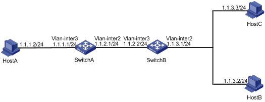
As shown in Figure 1, the interface of Host A and VLAN-interface 3 of Switch A are located on network segment 1.1.1.0/24. VLAN-interface 2 of Switch A and VLAN-interface 3 of Switch B are located on network segment 1.1.2.0/24. VLAN-interface 2 of Switch B, Host B, and Host C are located on network segment 1.1.3.0/24. The default gateway of Host A is VLAN-interface 3 (IP address 1.1.1.1/24) of Switch A. The default gateway of Host B and Host C is VLAN-interface 2 (IP address 1.1.3.1/24) of Switch B.
Configure static routes on Switch A and Switch B for reachability between Host A and Host B, and Host A and Host C, respectively.
Enable forwarding of directed broadcasts on Switch A and Switch B so that Host C and Host B can receive directed broadcasts from Host A.
Configuration procedure
1. Configure Switch A:
# Configure a static route on Switch A.
<SwitchA> system-view
[SwitchA] ip route-static 1.1.3.0 255.255.255.0 1.1.2.2
# Configure IP addresses for VLAN-interface 3 and VLAN-interface 2.
[SwitchA] interface vlan-interface 3
[SwitchA-Vlan-interface3] ip address 1.1.1.1 24
[SwitchA-Vlan-interface3] quit
[SwitchA] interface vlan-interface 2
[SwitchA-Vlan-interface2] ip address 1.1.2.1 24
# Enable VLAN-interface 2 to forward directed broadcasts.
[SwitchA-Vlan-interface2] ip forward-broadcast
2. Configure Switch B:
# Configure a static route on Switch B.
<SwitchB> system-view
[SwitchB] ip route-static 1.1.1.0 255.255.255.0 1.1.2.1
# Configure IP addresses for VLAN-interface 3 and VLAN-interface 2.
[SwitchB] interface vlan-interface 3
[SwitchB-Vlan-interface3] ip address 1.1.2.2 24
[SwitchB-Vlan-interface3] quit
[SwitchB] interface vlan-interface 2
[SwitchB-Vlan-interface2] ip address 1.1.3.1 24
# Enable VLAN-interface 2 to forward directed broadcasts.
[SwitchB-Vlan-interface2] ip forward-broadcast
Ping the subnet broadcast address 1.1.3.255 of VLAN-interface 2 of Switch B from Host A. The ping packets can be received by Host B and Host C.
Configuring the TCP send/receive buffer size
|
Step |
Command |
Remarks |
|
1. Enter system view. |
system-view |
N/A |
|
2. Configure the size of TCP receive/send buffer. |
tcp window window-size |
Optional. 8 KB by default. |
Configuring TCP timers
You can configure the following TCP timers:
· synwait timer—When sending a SYN packet, TCP starts the synwait timer. If no response packets are received within the synwait timer interval, the TCP connection cannot be created.
· finwait timer—When a TCP connection is changed into FIN_WAIT_2 state, the finwait timer is started. If no FIN packets are received within the timer interval, the TCP connection is terminated. If a FIN packet is received, the TCP connection state changes to TIME_WAIT. If a non-FIN packet is received, the system restarts the timer upon receiving the last non-FIN packet. The connection is broken after the timer expires.
To configure TCP timers:
|
Step |
Command |
Remarks |
|
1. Enter system view. |
system-view |
N/A |
|
2. Configure TCP timers. |
· Configure the TCP synwait timer: · Configure the TCP finwait timer: |
Optional. By default: · The TCP synwait timer is 75 seconds. · The TCP finwait timer is 675 seconds. |
|
|
IMPORTANT: The actual length of the finwait timer is determined by the following formula: Actual length of the finwait timer = (Configured length of the finwait timer – 75) + configured length of the synwait timer |
Configuring ICMP to send error packets
Sending error packets is a major function of ICMP protocol. In case of network abnormalities, error packets are usually sent by the network or transport layer protocols to notify corresponding switches so as to facilitate control and management.
Functions of sending ICMP error packets
ICMP error packets include the following types:
· ICMP redirect packets
A host might have only a default route to the default gateway in its routing table after startup. The default gateway will send ICMP redirect packets to the source host, telling it to reselect a correct next hop to send the subsequent packets, if the following conditions are met:
¡ The receiving and forwarding interfaces are the same.
¡ The selected route has not been created or modified by ICMP redirect packet.
¡ The selected route is not the default route of the switch.
¡ There is no source route option in the packet.
ICMP redirect packets function simplifies host administration and enables a host to gradually establish a sound routing table to find out the best route.
· ICMP timeout packets
If the switch receives an IP packet with a timeout error, it drops the packet and sends an ICMP timeout packet to the source.
The switch sends an ICMP timeout packet under the following conditions:
¡ If the switch finds the destination of a packet is not itself and the TTL field of the packet is 1, it will send a "TTL timeout" ICMP error message.
¡ When the switch receives the first fragment of an IP datagram whose destination is the switch itself, it starts a timer. If the timer times out before all the fragments of the datagram are received, the switch will send a "reassembly timeout" ICMP error packet.
· ICMP destination unreachable packets
The switch sends an ICMP destination unreachable packet under the following conditions:
¡ If a packet is destined for the switch but the transport layer protocol of the packet is not supported by the switch, the switch sends the source a Protocol Unreachable ICMP error packet.
¡ If a UDP packet is destined for the switch but the packet's port number does not match the corresponding process, the switch sends the source a Port Unreachable ICMP error packet.
¡ If the source uses Strict Source Routing to send packets, but the intermediate device finds that the next hop specified by the source is not directly connected, the switch sends the source a Source Routing Failure ICMP error packet. (The switch does not support this function.)
¡ If the MTU of the sending interface is smaller than the packet and the packet has DF set, the switch sends the source a Fragmentation Needed and DF-set ICMP error packet. (The switch does not support this function.)
¡ If a packet does not match any route and there is no default route in the routing table, the device sends a Network Unreachable ICMP error packet to the source. (The switch does not support this function.)
Disadvantages of sending ICMP error packets
Although sending ICMP error packets facilitates network control and management, it still has the following disadvantages:
· Sending a lot of ICMP packets increases network traffic.
· A device's performance degrades if it receives a lot of malicious packets that cause it to respond with ICMP error packets.
· A host's performance degrades if the redirection function increases the size of its routing table.
· End users can be affected if a host sends malicious ICMP destination unreachable packets.
To prevent such problems, you can disable the switch from sending ICMP error packets.
Configuration procedure
To disable sending ICMP error packets:
|
Step |
Command |
Remarks |
|
1. Enter system view. |
system-view |
N/A |
|
2. Enable sending ICMP error packets. |
· Enable sending ICMP redirect packets: · Enable sending ICMP timeout packets: · Enable sending ICMP destination unreachable packets: |
Disabled by default. |
|
|
NOTE: · You can configure this feature only on the VLAN interfaces of an Ethernet interface card. · When sending ICMP timeout packets is disabled, the switch will not send "TTL timeout" ICMP error packets. However, "reassembly timeout" error packets will be sent correctly. |
Enabling support for ICMP extensions
Generally, ICMP messages are of a fixed format and cannot carry extension information. With support for ICMP extensions enabled, a switch appends an extension information field to the ICMP messages as needed. The switch can append only MPLS label information to ICMP messages.
ICMP extensions for MPLS
In MPLS networks, when a packet's TTL expires, MPLS stripes the MPLS header, encapsulates the remaining datagram into an ICMP time exceeded message, and sends the message to the egress router of the MPLS tunnel. Then the egress router sends the message back to the ingress router of the tunnel. The ICMP message, however, does not contain the label information that is very important to the ingress router. With support for ICMP extensions enabled, the switch appends the MPLS label to the ICMP time exceeded message before sending it back to the ingress router of the tunnel.
ICMP extensions are usually used for an enhanced traceroute implementation in MPLS networks, in which MPLS label information about each hop the original datagram arrives at is printed.
Handling ICMP messages
ICMP messages can be classified into the following types:
· Common ICMP messages—Without any extension information.
· Extended ICMP messages with a length field—Carries extension information and a length field. The length field indicates the length of the original datagram that is encapsulated within the ICMP header and excludes the ICMP extension length. Such an ICMP message complies with RFC 4884.
· Extended ICMP messages without a length field—Carries extension information but does not contain a length field. Such an ICMP message does not comply with RFC 4884.
Based on how these messages are handled, the switch can operate in one of these modes: common mode, compliant mode, and non-compliant mode. Table 1 shows how ICMP messages are handled in different operating modes.
Table 1 Handling ICMP messages
|
Device mode |
ICMP messages sent |
ICMP messages received |
Remarks |
|
Common mode |
Common ICMP messages |
Common ICMP messages |
Extension information in extended ICMP messages will not be processed. |
|
Compliant mode |
Common ICMP messages Extended ICMP messages with a length field |
Common ICMP messages Extended ICMP messages with a length field |
Extended ICMP messages without a length field are handled as common ICMP messages. |
|
Non-compliant mode |
Common ICMP messages Extended ICMP messages without a length field |
All three types of ICMP messages |
N/A |
|
|
NOTE: ICMP/ICMPv6 messages that can carry extension information include only IPv4 redirect messages, IPv4/IPv6 time exceeded messages, and IPv4/IPv6 destination unreachable messages. |
Configuration procedure
To enable support for ICMP extensions:
|
Step |
Command |
Remarks |
|
|
1. Enter system view. |
system-view |
N/A |
|
|
2. Enable support for ICMP extensions. |
· In compliant mode: · In non-compliant mode: |
Optional. Disabled by default. |
|
|
|
NOTE: After support for ICMP extensions is disabled, no ICMP message sent by the switch contains extension information. |
Enabling ICMP flow control
If a large number of ICMP packets are delivered to the CPU for processing, processing of other services is affected. To prevent this, you can enable ICMP flow control.
To enable ICMP flow control:
|
Step |
Command |
Remarks |
|
1. Enter system view. |
system-view |
N/A |
|
2. Enable ICMP flow control. |
ip icmp flow-control |
Disabled by default. |
Displaying and maintaining IP performance optimization
|
Task |
Command |
Remarks |
|
Display TCP connection statistics. |
display tcp statistics [ | { begin | exclude | include } regular-expression ] |
Available in any view. |
|
Display UDP statistics. |
display udp statistics [ | { begin | exclude | include } regular-expression ] |
Available in any view. |
|
Display statistics of IP packets (in standalone mode). |
display ip statistics [ slot slot-number ] [ | { begin | exclude | include } regular-expression ] |
Available in any view. |
|
Display statistics of IP packets (in IRF mode). |
display ip statistics [ chassis chassis-number slot slot-number ] [ | { begin | exclude | include } regular-expression |
Available in any view. |
|
Display statistics of ICMP flows (in standalone mode). |
display icmp statistics [ slot slot-number ] [ | { begin | exclude | include } regular-expression ] |
Available in any view. |
|
Display statistics of ICMP flows (in IRF mode). |
display icmp statistics [ chassis chassis-number slot slot-number ] [ | { begin | exclude | include } regular-expression ] |
Available in any view. |
|
Display socket information (in standalone mode). |
display ip socket [ socktype sock-type ] [ task-id socket-id ] [ slot slot-number ] [ | { begin | exclude | include } regular-expression |
Available in any view. |
|
Display socket information (in IRF mode). |
display ip socket [ socktype sock-type ] [ task-id socket-id ] [ chassis chassis-number slot slot-number ] [ | { begin | exclude | include } regular-expression ] |
Available in any view. |
|
Clear statistics of IP packets (in standalone mode). |
reset ip statistics [ slot slot-number ] |
Available in user view. |
|
Clear statistics of IP packets (in IRF mode). |
reset ip statistics [ chassis chassis-number slot slot-number ] |
Available in user view. |
|
Clear statistics of TCP connections. |
reset tcp statistics |
Available in user view. |
|
Clear statistics of UDP traffic. |
reset udp statistics |
Available in user view. |