- Table of Contents
-
- 06-Layer 3 - IP Services Configuration Guide
- 00-Preface
- 01-ARP Configuration
- 02-IP Addressing Configuration
- 03-DHCP Configuration
- 04-DNS Configuration
- 05-NAT Configuration
- 06-IP Forwarding Basics Configuration
- 07-Adjacency Table Configuration
- 08-IP Performance Optimization Configuration
- 09-UDP helper Configuration
- 10-IPv6 Basics Configuration
- 11-DHCPv6 Configuration
- 12-IPv6 DNS Configuration
- 13-Tunneling Configuration
- 14-GRE Configuration
- Related Documents
-
| Title | Size | Download |
|---|---|---|
| 05-NAT Configuration | 294.53 KB |
Contents
Configuration restrictions and guidelines
Configuring address translation
Configuring an internal server
Introduction to internal server
Introduction to connection limit
Enabling aging out NAT entries upon master link failure
Displaying and maintaining NAT
One-to-one static NAT configuration example
Dynamic NAT configuration example
Internal server configuration example
NAT DNS mapping configuration example
Exporting NAT logs to the information center
Exporting NAT logs to log server
You cannot configure NAT after you configure local PBR or interface PBR. For more information about PBR, see Layer 3—IP Routing Configuration Guide.
Overview
Network Address Translation (NAT) provides a way of translating the IP address in an IP packet header to another IP address. In practice, NAT is primarily used to allow users using private IP addresses to access public networks. With NAT, a smaller number of public IP addresses are used to enable a larger number of internal hosts to access the Internet. Thus, NAT effectively alleviates the depletion of IP addresses.
A private or internal IP address is used only in an internal network, whereas a public or external IP address is used on the Internet and is globally unique.
According to RFC 1918, three blocks of IP addresses are reserved for private networks:
· In Class A, 10.0.0.0 to 10.255.255.255.
· In Class B, 172.16.0.0 to 172.31.255.255.
· In Class C, 192.168.0.0 to 192.168.255.255.
No host with an IP address in the three ranges exists on the Internet. You can use those IP addresses in an enterprise network freely without requesting them from an ISP or a registration center.
In addition to translating private addresses to public addresses, NAT can also perform address translation between any two networks. In this document, the two networks refer to an internal network and an external network. Generally, a private network is an internal network, and a public network is an external network.
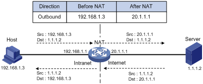
1. The internal host with an IP address of 192.168.1.3 sends an IP packet to the external server with an IP address of 1.1.1.2 through the NAT device.
2. Upon receiving the packet, the NAT device checks the IP header and finds that it is destined to the external network. Then it translates the private address 192.168.1.3 to the globally unique public address 20.1.1.1 and then forwards the packet to the server on the external network. Meanwhile, the NAT device adds the mapping of the two addresses into its NAT table.
3. The external server responds to the internal host with an IP packet whose destination IP address is 20.1.1.1. Upon receiving the packet, the NAT device checks the IP header, looks into its NAT table for the mapping, replaces the destination address with the private address of 192.168.1.3, and then sends the new packet to the internal host.
The NAT operation is transparent to the terminals involved. The external server believes that the IP address of the internal PC is 20.1.1.1 and is unaware of the private address 192.168.1.3. As such, NAT hides the private network from the external networks.
Despite the advantages of allowing internal hosts to access external resources and providing privacy, NAT also has the following disadvantages:
· As NAT involves translation of IP addresses, the IP headers cannot be encrypted. This is also true to the application protocol packets when the contained IP address or port number needs to be translated. For example, you cannot encrypt an FTP connection, or its port command cannot work correctly.
· Network debugging becomes more difficult. For example, when a host in a private network tries to attack other networks, it is harder to pinpoint the attacking host as the host IP address has been hidden.
NAT control
In practice, an enterprise needs to allow some hosts in the internal network to access external networks and prohibit others. This can be achieved through the NAT control mechanism. If a source IP address is among addresses denied, the NAT device does not translate the address. In addition, the NAT device only translates private addresses to specified public addresses.
NAT control can be achieved through an access control list (ACL) and an address pool.
· Only packets matching the ACL rules are served by NAT.
· An address pool is a collection of consecutive public IP addresses for address translation. You can specify an address pool based on the number of available public IP addresses, the number of internal hosts, and network requirements. The NAT device selects an address from the address pool as the public address of an IP packet.
NAT operation
Basic NAT
As shown in Figure 1, when an internal host accesses an external network, the NAT device uses a public IP address to replace the private source original internal IP address. In Figure 1, NAT uses the IP address of the outgoing interface as the public IP address. All internal hosts use the same public IP address to access external networks and only one host is allowed to access external networks at a given time.
A NAT device gateway can also hold multiple public IP addresses to support concurrent access requests. Whenever a new external network access request comes from the internal network, the NAT device chooses an available public IP address (if any) to replace the source IP address, adds the mapping to its NAT table, forwards the packet, and records the mapping between the two addresses. In this way, multiple internal hosts can access external networks simultaneously.
|
|
NOTE: The number of public IP addresses that a NAT device needs is usually far less than the number of internal hosts because not all internal hosts access external networks at the same time. The number of public IP addresses is related to the number of internal hosts that might access external networks simultaneously during peak hours. |
NAPT
Network Address Port Translation (NAPT) is a variation of basic NAT. It allows multiple internal addresses to be mapped to the same public IP address, which is called multiple-to-one NAT, or address multiplexing.
NAPT mapping is based on both the IP address and the port number. With NAPT, packets from multiple internal hosts are mapped to the same external IP address with different port numbers.
Figure 2 NAPT operation
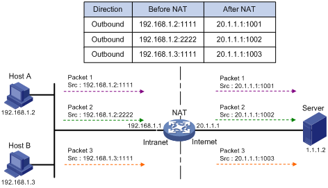
As shown in Figure 2, three IP packets arrive at the NAT device. Packets 1 and 2 are from the same internal address but have different source port numbers. Packets 1 and 3 are from different internal addresses but have the same source port number. NAPT maps the three IP packets to the same external address but with different source port numbers. Therefore, the packets can still be differentiated. When receiving the response packets, the NAT device forwards them to the corresponding hosts according to the destination addresses and port numbers.
NAPT can better utilize IP address resources, enabling more internal hosts to access the external network at the same time.
Internal server
NAT hides the internal network structure, including the identities of internal hosts. However, some internal hosts such as an internal web server or FTP server might need to be accessed by external hosts. NAT meets this need by supporting internal servers.
You can configure an internal server on the NAT device by mapping a public IP address and port number to the private IP address and port number of the internal server. For instance, you can configure an address like 20.1.1.12:8080 as an internal web server’s external address and port number.
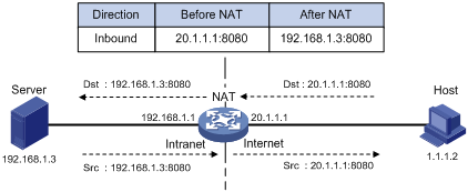
In Figure 3, when the NAT device receives a packet destined for the public IP address of an internal server, it looks in the NAT entries and translates the destination address and port number in the packet to the private IP address and port number of the internal server. When the NAT device receives a response packet from the internal server, it translates the source private IP address and port number of the packet into the public IP address and port number of the internal server.
Figure 3 Internal server operation
DNS mapping
Generally, the DNS server and users that need to access internal servers reside on the public network. You can specify an external IP address and port number for an internal server on the public network interface of a NAT device, so that external users can access the internal server using its domain name or pubic IP address. In Figure 4, an internal host wants to access an internal web server by using its domain name, and the DNS server is located on the public network. The DNS server replies with the public address of the internal server to the host and the host cannot access the internal server. The DNS mapping feature can solve the problem.
Figure 4 NAT DNS mapping operation
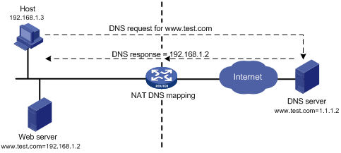
A DNS mapping entry records the domain name, public address, public port number, and protocol type of an internal server. Upon receiving a DNS reply, the NAT-enabled interface matches the domain name in the message against the DNS mapping entries. If a match is found, the private address of the internal server is found and the interface replaces the public IP address in the reply with the private IP address. Then, the host can use the private address to access the internal server.
Easy IP
Easy IP uses the public IP address of an interface on the switch as the translated source address to save IP address resources, and uses ACLs to permit only certain internal IP addresses to be NATed.
Support for special protocols
Apart from the basic address translation function, NAT also provides an application layer gateway (ALG) mechanism that supports some special application protocols without requiring the NAT platform to be modified, featuring high scalability. The IP addresses or port numbers contained in such protocol messages might need address translation.
The special protocols that NAT supports include: File Transfer Protocol (FTP), Internet Control Message Protocol (ICMP), Domain Name System (DNS), Internet Locator Service (ILS), H.323, Session Initiation Protocol (SIP), Netmeeting 3.01, and NetBIOS over TCP/IP (NBT).
NAT support for MPLS VPNs
NAT allows users from different MPLS VPNs to access external networks through the same outbound interface, and allows the VPN users to use the same private address space.
1. Upon receiving a request from an MPLS VPN to an external network, NAT replaces the private source IP address and port number with a public IP address and port number, and records the MPLS VPN information, such as the protocol type and router distinguisher (RD).
2. When the response packet arrives, NAT replaces the public destination IP address and port number with the internal IP address and port number, and sends the packet to the target MPLS VPN. Both NAT and NAPT support MPLS VPNs.
This feature can also apply to internal servers so that external users can access an internal host of an MPLS VPN. For example, suppose a host in MPLS VPN 1 needs to provide web services for the Internet. It has a private address of 10.110.1.1. To achieve this purpose, configure NAT to use 202.110.10.20 as the public IP address of the host so that the Internet users can use this IP address to access web services on the host.
NAT allows hosts in multiple MPLS VPNs to access each other by using the MPLS VPN information carried in the external IP address.
Configuration restrictions and guidelines
If the NAT configuration (address translation or internal server configuration) on an interface is changed, H3C recommends that you save the configuration and reboot the switch (or use the reset nat session command to manually clear the relevant NAT entries), to avoid problems. The following problems might occur: after you delete the NAT-related configuration, address translation can still work for sessions already created. If you configure NAT when NAT is running, the same configuration might have different results because of different configuration orders.
Make sure all the IP address pools applied to the interfaces do not overlap.
NAT configuration task list
|
Task |
Remarks |
|
|
Either is required. |
||
|
Required. |
||
|
Optional. |
||
|
Optional. |
||
|
Optional. |
||
|
Optional. |
||
|
Optional. |
||
|
Optional. |
||
Configuring address translation
A NAT device can be configured with or dynamically generate mappings to translate between internal and external network addresses. Address translation can be classified into the following types:
· Static NAT—Mappings between external and internal network addresses are manually configured. Static NAT can meet fixed access requirements of a few users.
· Dynamic NAT—A dynamic NAT entry is generated dynamically. Dynamic ANT is implemented by associating an ACL with an address pool (or the address of an interface in the case of Easy IP). This association defines what packets can use the addresses in the address pool (or the interface’s address) to access the external network. Dynamic NAT is applicable to the network environment where a large number of internal users need to access external networks. An IP address is selected from the associated address pool to translate an outgoing packet. After the session terminates, the selected IP address is released.
Both static NAT and dynamic NAT support NAT multiple-instance as long as the VPN instance of an IP address is provided.
Configuring static NAT
You need to configure static NAT in system view, and make it effective in interface view.
Static NAT supports two modes: one-to-one and net-to-net.
Configuring one-to-one static NAT
One-to-one static NAT translates a private IP address into a public IP address.
To configure one-to-one static NAT:
|
Step |
Command |
|
1. Enter system view. |
system-view |
|
2. Configure a one-to-one static NAT mapping. |
nat static local-ip [ vpn-instance local-name ] global-ip [ vpn-instance global-name ] |
|
3. Enter interface view. |
interface interface-type interface-number |
|
4. Enable static NAT on the interface. |
nat outbound static |
Configuring net-to-net static NAT
Net-to-net static NAT translates a private network into a public network.
To configure net-to-net static NAT:
|
Step |
Command |
|
1. Enter system view. |
system-view |
|
2. Configure a net-to-net static NAT mapping. |
nat static net-to-net local-start-address local-end-address global global-network { netmask-length | netmask } |
|
3. Enter interface view. |
interface interface-type interface-number |
|
4. Enable static NAT on the interface. |
nat outbound static |
Configuring dynamic NAT
Dynamic NAT is usually implemented by associating an ACL with an address pool (or the address of an interface) on an interface.
· To select the address of an interface as the translated address, use Easy IP.
· To select an address from an address pool as the translated address, use No-PAT or NAPT for dynamic address translation. No-PAT is used in many-to-many address translation but does not translate TCP/UDP port numbers. NAPT allows for many-to-one address translation by translating also TCP/UDP port numbers.
A NAT entry is configured on the outbound interface of the NAT device. If internal hosts need to access external networks through multiple outbound interfaces on the NAT device, you must configure NAT entries on each of the interfaces. To avoid this, the switch supports configuring a NAT entry on the inbound interface on the NAT device. When hosts in a VPN want to access other VPNs through multiple outbound interfaces on a NAT device, you can configure a NAT entry on the inbound interface on the NAT device, simplifying NAT configuration.
When a packet from an internal host to the external network arrives:
· If it is the first packet and an address pool is associated with an outbound interface, NAT determines whether to translate the packet based on the ACL (or its source IP address). If yes, NAT chooses an address from the associated address pool or gets the associated interface address, performs address translation, and then saves the address mapping in the address translation table. All subsequent packets from the internal host are serviced by NAT directly according to the mapping entry.
· If an address pool is associated with an inbound interface, NAT determines whether to translate the packet based on the ACL (or packet source address). If yes, NAT redirects the packet to the NAT board and performs address translation as in the above-mentioned process. This case does not support Easy IP.
|
|
NOTE: If both the inbound and outbound interfaces of a NAT device are associated with an address pool, a packet matching both of them uses an address from the address pool associated with the outbound interface for address translation. |
Configuration prerequisites
· Configure an ACL to specify IP addresses permitted to be translated. For more information about ACL, see ACL and QoS Configuration Guide.
· Determine whether to use an interface’s IP address as the translated source address.
· Determine a public IP address pool for address translation.
· Determine whether to translate port information.
Configuring NAT address pool
In dynamic address translation, the NAT device selects an address from a specific NAT address pool as the source address of a packet.
To configure a NAT address pool:
|
Step |
Command |
Remarks |
|
1. Enter system view. |
system-view |
N/A |
|
Configure an address pool. |
nat address-group group-number start-address end-address |
Not necessary when the router provides only Easy IP, where an interface’s public IP address is used as the translated IP address. |
Configuring Easy IP
Easy IP allows the switch to use the IP address of one of its interfaces as the source address of NATed packets.
To configure Easy IP:
|
Step |
Command |
|
1. Enter system view. |
system-view |
|
2. Enter interface view. |
interface interface-type interface-number |
|
3. Enable Easy IP by associating an ACL with the IP address of the interface. |
nat outbound acl-number |
Configuring No-PAT
With a specific ACL associated with an address pool or interface address, No-PAT translates the source address of a packet permitted by the ACL into an IP address of the address pool or the interface address, without using the port information.
To configure No-PAT:
|
Step |
Command |
|
1. Enter system view. |
system-view |
|
2. Enter interface view. |
interface interface-type interface-number |
|
3. Configure No-PAT by associating an ACL with an IP address pool on the outbound interface for translating only IP addresses. |
nat outbound acl-number [ address-group group-number [ vpn-instance vpn-instance-name ] [ no-pat ] ] |
Configuring NAPT
With a specific ACL associated with an address pool or interface address, NAPT translates the source address of a packet permitted by the ACL into an IP address of the address pool or the interface address, with using the port information.
To configure NAPT:
|
Step |
Command |
|
1. Enter system view. |
system-view |
|
2. Enter interface view. |
interface interface-type interface-number |
|
3. Configure NAPT by associating an ACL with an IP address pool on the outbound interface for translating both IP address and port number. |
nat outbound acl-number address-group group-number [ vpn-instance vpn-instance-name ] |
Configuring an internal server
Introduction to internal server
To configure an internal server, you need to map an external IP address and port number to the internal server. This is done through executing the nat server command on an interface.
Internal server configurations include external network information (external IP address global-address and external port number global-port), internal network information (internal IP address local-address and internal port number local-port), and internal server protocol type.
Configuration procedure
After mapping the private IP address/port number (local-address and local-port) of an internal server to a public IP address/port number (global-address and global-port), hosts in external networks can access the server located in the private network.
Both internal servers and their external IP addresses can support MPLS L3VPN. If an internal server belongs to an MPLS L3VPN, you also need to specify the vpn-instance-name argument. Without this argument specified, the internal server does not belong to any VPN.
To configure an internal server:
|
Step |
Command |
Remarks |
|
1. Enter system view. |
system-view |
N/A |
|
2. Enter interface view. |
interface interface-type interface-number |
N/A |
|
3. Configure an internal server. |
· nat server protocol pro-type global { global-address | interface interface-type interface-number | current-interface } [ global-port ] [ vpn-instance global-name ] inside local-address [ local-port ] [ vpn-instance local-name ] · nat server protocol pro-type global { global-address | interface interface-type interface-number | current-interface } global-port1 global-port2 [ vpn-instance global-name ] inside local-address1 local-address2 local-port [ vpn-instance local-name ] |
Use either command. |
Configuring DNS mapping
With DNS mapping, an internal host can access an internal server on the same private network by using the domain name of the internal server when the DNS server resides on the public network.
To configure a DNS mapping:
|
Step |
Command |
|
1. Enter system view. |
system-view |
|
2. Configure a DNS mapping. |
nat dns-map domain domain-name protocol pro-type ip global-ip port global-port |
Configuring NAT aging time
NAT aging time configuration supports multiple protocols.
To set the NAT aging time:
|
Step |
Command |
Remarks |
|
1. Enter system view. |
system-view |
N/A |
|
2. Set NAT aging time for a specific protocol. |
nat aging-time { dns | ftp-ctrl | ftp-data | icmp | no-pat | pptp | tcp | tcp-fin | tcp-syn | udp } seconds |
Optional. The default NAT aging time varies by protocol: · 10 seconds for DNS. · 300 seconds for FTP control links. · 300 seconds for FTP data links. · 10 seconds for ICMP. · 240 seconds in NO-PAT mode. · 300 seconds for PPTP. · 300 seconds for TCP. · 10 seconds for TCP FIN and RST connections. · 10 seconds for TCP SYN connections. · 240 seconds for UDP. |
Configuring NAT ALG
NAT ALG configuration supports multiple protocols.
To configure NAT ALG:
|
Step |
Command |
Remarks |
|
1. Enter system view. |
system-view |
N/A |
|
2. Enable NAT ALG. |
nat alg { all | dns | ftp | h323 | ils | nbt | sip } |
Optional. By default, NAT ALG is enabled. |
Configuring NAT logging
Introduction to NAT logging
With NAT logging enabled, a NAT device logs IP address translation information such as the source IP address, source port number, destination IP address, destination port number, translated source IP address, translated source port number and user operations.
As multiple internal users share the same external IP address or the same range of external IP addresses when accessing external networks through a NAT device, it is hard to identify each of the users. The NAT logging function helps in tracking access of internal users to external networks, thus enhancing network security.
Note that NAT logging logs only access of internal network users to external networks. It does not log access of external users to internal servers.
Enabling NAT logging
|
Step |
Command |
Remarks |
|
1. Enter system view. |
system-view |
N/A |
|
2. Enable NAT logging. |
nat log enable [ acl acl-number ] |
Disabled by default. |
|
3. Enable NAT logging. |
· Enable logging of NAT session establishment
events: · Enable logging for active NAT sessions and set the logging
interval: |
Use either command. By default: · No log is generated when a NAT session is established. · Logging for active NAT sessions is disabled by default. |
Exporting NAT logs
NAT logs can be exported to either the information center or the log server:
· To the information center—NAT logs are converted into system logs and exported to the local switch’s information center. Depending on the configuration of the information center, NAT logs are then exported to their final destination. Up to 10 NAT logs can be exported to the information center at one time.
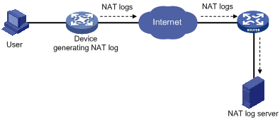
· To the log server—NAT logs are encapsulated into UDP packets and sent to the log server, as shown in Figure 5. The output NAT logs can be in several versions, each with a different UDP packet format. Only version 1 is used. A UDP packet is composed of a header and one or more NAT logs.
|
|
NOTE: NAT logs can be exported to the information center or the log server. If you configure both destinations, the system automatically exports NAT logs to the information center, rather than to the log server. |
Exporting NAT logs to the information center
Exporting NAT logs to the information center consumes storage space of the switch. H3C recommends this method when the volume of NAT logs is relatively small.
NAT logs exporting to the information center are prioritized as informational, meaning that they are ordinary prompt information. For more information about NAT log priority, see Network Management and Monitoring Configuration Guide.
To export NAT logs to the information center:
|
Step |
Command |
Remarks |
|
1. Enter system view. |
system-view |
N/A |
|
2. Export NAT logs to the information center. |
userlog nat syslog |
By default, NAT logs are exported to the NAT log server. |
Exporting NAT logs to the log server
For the switch to export NAT logs to the log server in UDP packets, you can configure the following parameters:
· IP address and UDP port number of the NAT log server. NAT logs cannot be exported successfully if you do not configure the information center export direction and specify the log server address.
· Source IP address of NAT logs. This address allows the log server to identify the log source. H3C recommends that you use the loopback interface address as the source IP address of NAT logs.
· Version number of NAT logs. NAT logs might come in several versions, each with a different packet format. The switch supports only version 1.
Follow these guidelines when you export NAT logs to a NAT log server:
· When the switch is operating in standalone mode, you can specify a separate log server for each interface card identified by slot slot-number to implement load sharing on log servers.
· When the switch is operating in IRF mode, you can specify a separate log server for each interface card identified by chassis chassis-number to implement load sharing on log servers.
· The IP address of the NAT log server must be a valid IPv4 or IPv6 unicast address.
· A port number greater than 1024 is recommended to avoid conflicting with the system-defined port numbers.
To configure the switch to export NAT logs to a NAT log server:
|
Step |
Command |
Remarks |
|
1. Enter system view. |
system-view |
N/A |
|
2. Specify the IP address and UDP port number of the NAT log server. |
· In standalone mode: · In IRF mode: |
N/A |
|
3. Specify the source IP address for the UDP packets that carry NAT logs. |
userlog nat export source-ip ip-address |
Optional. By default, the source IP address is the IP address of the interface through which the UDP packets are sent. |
|
4. Specify the version number of the NAT log packets. |
userlog nat export version version-number |
Optional. Version 1 by default. |
Setting NAT connection limit
Introduction to connection limit
To avoid such situations, you can configure a connection limit policy to limit the number of connections, connection rate, and connection bandwidth. The limits to the connection rate and bandwidth cannot be specified at the same time.
Configuring connection limit
Creating a connection limit policy
|
Step |
Command |
|
1. Enter system view. |
system-view |
|
2. Create a connection limit policy and enter its view. |
connection-limit policy policy-number |
Configuring the default connection limit action/parameters
For user connections not specifically limited by the connection limit policy, the default connection limit action applies.
· If the default connection limit action is deny, the user connections are not counted or limited.
· If the default connection limit action is permit, the user connections are limited according to the configured default connection limit parameters. When the number of connections reaches the upper limit, the user cannot establish new connections. When the connection number goes below the lower limit, the user can establish new connections.
To validate default connection limit parameters, you must bind the connection limit policy to the NAT module. For more information about binding the connection limit policy to the NAT module, see "Binding the connection limit policy to the NAT module."
To configure the default connection limit action/parameters:
|
Step |
Command |
Remarks |
|
1. Enter system view. |
system-view |
N/A |
|
2. Enter connection limit policy view. |
connection-limit policy policy-number |
N/A |
|
3. Set the default connection limit action. |
connection-limit default action { deny | permit } |
Optional. The default is deny. User connections are not counted and limited. |
|
4. Set the default connection limit parameters. |
connection-limit default amount upper-limit max-amount lower-limit min-amount |
Optional. By default, the upper limit is 512, and the lower limit is 256. |
Configuring the connection limit policy
You can configure multiple limit rules (identified by limit ID) for a connection limit policy. A limit rule allows you to reference an ACL to limit and count user connections matching the ACL, and specify limit types and maximum and minimum connection numbers. The limit rules are applied in the ascending order of limit IDs.
When the maximum connection number of a limit type is reached, the switch will not accept new connections of this type until its minimum connection number is reached.
An ACL-based connection limit rule supports the following limit types:
· per-destination—Limits connections to the same destination IP address.
· per-service—Limits connections of the same service (or an application).
· per-source—Limits connections from the same source IP address.
If you specify multiple limit types in one limit rule, they work together to limit and count user connections. For example, with both per-destination and per-service limit types specified, the limit rule limits and counts the user connections of the same service that are destined to the same destination IP address.
To configure an ACL-based connection limit policy:
|
Step |
Command |
|
1. Enter system view. |
system-view |
|
2. Enter connection limit policy view. |
connection-limit policy policy-number |
|
3. Configure an ACL-based limit rule. |
limit limit-id acl acl-number [ { per-destination | per-service | per-source } * amount max-amount min-amount ] |
|
|
NOTE: The default connection limit parameters apply to the unmatched user connections. |
Binding the connection limit policy to the NAT module
In this task, you can bind the configured connection limit policy to the NAT module for connection limit.
Follow these guidelines when you bind the connection limit policy to the NAT module:
· A NAT module can be bound with only one connection limit policy.
· The default connection limit parameters take effect after you bind the connection limit policy to the NAT module.
To bind the connection limit policy to the NAT module:
|
Step |
Command |
|
1. Enter system view. |
system-view |
|
2. Bind the connection limit policy to the NAT module. |
nat connection-limit-policy policy-number |
Enabling aging out NAT entries upon master link failure
In a link backup environment where NAT is enabled on the master and backup interfaces of a gateway switch, if the master link fails, the backup link switches to the master state. If this feature is enabled on the switch, all existing NAT entries on the failed link will be aged out immediately, so that new NAT entries can be created for subsequent packets on the new master link, and thus NAT streams can be directed to the new link immediately.
To enable aging out NAT entries upon master link failure:
|
Step |
Command |
Remarks |
|
1. Enter system view. |
system-view |
N/A |
|
2. Enable aging out NAT entries upon master link failure. |
nat link-down reset-session enable |
Disabled by default. |
Displaying and maintaining NAT
|
|
CAUTION: Clearing the NAT log buffer implies loss of all NAT logs. In general, H3C recommends not using this command. |
|
Task |
Command |
Remarks |
|
Display information about NAT address pools. |
display nat address-group [ group-number ] [ | { begin | exclude | include } regular-expression ] |
Available in any view. |
|
Display the NAT aging time settings for various protocols. |
display nat aging-time [ | { begin | exclude | include } regular-expression ] |
Available in any view. |
|
Display all NAT configuration information. |
display nat all [ | { begin | exclude | include } regular-expression ] |
Available in any view. |
|
Display connection limit information. |
display nat connection-limit [ source src-address { mask-length | mask } ] [ destination dst-address { mask-length | mask } ] [ destination-port { eq | gt | lt | neq | range } port-number ] [ vpn-instance vpn-instance-name ] [ | { begin | exclude | include } regular-expression ] |
Available in any view. |
|
Display NAT configuration information. |
display nat bound [ | { begin | exclude | include } regular-expression ] |
Available in any view. |
|
Display DNS mapping configuration information. |
display nat dns-map [ | { begin | exclude | include } regular-expression ] |
Available in any view. |
|
Display internal server information. |
display nat server [ | { begin | exclude | include } regular-expression ] |
Available in any view. |
|
Display static NAT information. |
display nat static [ | { begin | exclude | include } regular-expression ] |
Available in any view. |
|
Display dynamic NAT entries on the specified board (in standalone mode). |
display nat session [ vpn-instance vpn-instance-name ] slot slot-number [ source { global global-address | inside inside-address } ] [ destination dst-address ] [ | { begin | exclude | include } regular-expression ] |
Available in any view. |
|
Display dynamic NAT entries on the specified board (in IRF mode). |
display nat session [ vpn-instance vpn-instance-name ] chassis chassis-number slot slot-number [ source { global global-address | inside inside-address } ] [ destination dst-address ] [ | { begin | exclude | include } regular-expression ] |
Available in any view. |
|
Display information about the connection limit policy. |
display connection-limit policy { policy-number | all } [ | { begin | exclude | include } regular-expression ] |
Available in any view. |
|
Display connection limit statistics. |
display connection-limit statistics [ source src-address { mask-length | mask } ] [ destination dst-address { mask-length | mask } ] [ destination-port { eq | gt | lt | neq | range } port-number ] [ vpn-instance vpn-instance-name ] [ | { begin | exclude | include } regular-expression ] |
Available in any view. |
|
Display NAT log information. |
display nat log [ | { begin | exclude | include } regular-expression ] |
Available in any view. |
|
Display user logs output to the log server through a specific interface board (in standalone mode). |
display userlog export slot slot-number [ | { begin | exclude | include } regular-expression ] |
Available in any view. |
|
Display user logs output to the log server through a specific interface board (in IRF mode). |
display userlog export chassis chassis-number slot slot-number [ | { begin | exclude | include } regular-expression ] |
Available in any view. |
|
Clear the records in the NAT log buffer on a specific interface board (in standalone mode). |
reset userlog nat logbuffer slot slot-number |
Available in user view. |
|
Clear the records in the NAT log buffer on a specific interface board (in IRF mode). |
reset userlog nat logbuffer chassis chassis-number slot slot-number |
Available in user view. |
|
Clear the statistics of NAT logs on a specific interface board (in standalone mode). |
reset userlog nat export slot slot-number |
Available in user view. |
|
Clear the statistics of NAT logs on a specific interface board (in IRF mode). |
reset userlog nat export chassis chassis-number slot slot-number |
Available in user view. |
|
Clear the NAT mapping table and release the corresponding storage space on a specific interface board (in standalone mode). |
reset nat session slot slot-number |
Available in user view. |
|
Clear the NAT mapping table and release the corresponding storage space on a specific interface board (in IRF mode). |
reset nat session chassis chassis-number slot slot-number |
Available in user view. |
NAT configuration examples
|
|
IMPORTANT: By default, Ethernet, VLAN, and aggregate interfaces are down. To configure such an interface, bring the interface up by using the undo shutdown command. |
One-to-one static NAT configuration example
Network requirements
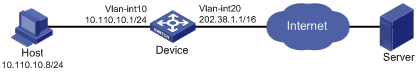
An internal host 10.110.10.8/24 uses public address 202.38.1.100 to access the Internet.
Configuration procedure
# Specify IP addresses for the interfaces, as shown in Figure 6. (Details not shown.)
# Configure an one-to-one static NAT mapping.
<Device> system-view
[Device] nat static 10.110.10.8 202.38.1.100
# Enable static NAT on VLAN-interface 20.
[Device] interface Vlan-interface 20
[Device-Vlan-interface20] nat outbound static
[Device-Vlan-interface20] quit
Dynamic NAT configuration example
Network requirements
As shown in Figure 7, a company has three public IP addresses in the range of 202.38.1.1/24 to 202.38.1.3/24, and an internal network address of 10.110.0.0/16. The company has the following requirements:
· The internal users in subnet 10.110.10.0/24 can access the Internet using public IP addresses 202.38.1.2 and 202.38.1.3, but users in other network segments cannot.
· Configure the upper and lower limits of connections sourced from 10.110.10.100 as 1000 and 200 respectively.
Configuration procedure
# Specify IP addresses for the interfaces, as shown in Figure 7. (Details not shown.)
# Configure address pool 1.
<Device> system-view
[Device] nat address-group 1 202.38.1.2 202.38.1.3
# Configure ACL 2001, and create a rule to permit only users from network segment 10.110.10.0/24 to access the Internet.
[Device] acl number 2001
[Device-acl-basic-2001] rule permit source 10.110.10.0 0.0.0.255
[Device-acl-basic-2001] rule deny
[Device-acl-basic-2001] quit
# Associate address pool 1 and ACL 2001 with the outbound interface VLAN-interface 20.
[Device] interface Vlan-interface 20
[Device-Vlan-interface20] nat outbound 2001 address-group 1
[Device-Vlan-interface 20] quit
# Configure connection limit policy 1 to limit user connections sourced from 10.110.10.100. Set the upper and lower limits to 1000 and 200 respectively.
[Device] acl number 2002
[Device-acl-basic-2002] rule permit source 10.110.10.100 0.0.0.0
[Device-acl-basic-2002] rule deny
[Device-acl-basic-2002] quit
[Device] connection-limit policy 1
[Device-connection-limit-policy-1] limit 0 acl 2002 per-destination amount 1000 200
[Device-connection-limit-policy-1] quit
# Bind connection limit policy 1 to NAT.
[Device] nat connection-limit-policy 1
Internal server configuration example
Network requirements
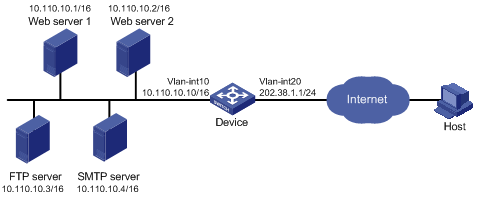
As shown in Figure 8, a company provides two web servers, one FTP server, and one SMTP server for external users to access. The internal network address is 10.110.0.0/16. The internal address for the FTP server is 10.110.10.3/16, for the web server 1 is 10.110.10.1/16, for the web server 2 is 10.110.10.2/16, and for the SMTP server 10.110.10.4/16. The company has three public IP addresses in the range of 202.38.1.1/24 to 202.38.1.3/24. Specifically, the company has the following requirements:
· External hosts can access internal servers with public address 202.38.1.1/24.
· Port 8080 is used for web server 2.
Configuration procedure
# Specify IP addresses for the interfaces, as shown in Figure 8. (Details not shown.)
# Enter interface VLAN-interface 20 view.
<Device> system-view
[Device] interface vlan-interface 20
# Configure the internal FTP server.
[Device-Vlan-interface20] nat server protocol tcp global 202.38.1.1 21 inside 10.110.10.3 ftp
# Configure the internal web server 1.
[Device-Vlan-interface20] nat server protocol tcp global 202.38.1.1 80 inside 10.110.10.1 www
# Configure the internal web server 2.
[Device-Vlan-interface20] nat server protocol tcp global 202.38.1.1 8080 inside 10.110.10.2 www
# Configure the internal SMTP server.
[Device-Vlan-interface20] nat server protocol tcp global 202.38.1.1 smtp inside 10.110.10.4 smtp
[Device-Vlan-interface20] quit
NAT DNS mapping configuration example
Network requirements
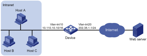
A company provides web and FTP services to external users, and has its internal IP addresses on the network segment 10.110.0.0/16. The IP addresses of the web and FTP servers are 10.110.10.1/16 and 10.110.10.2/16 respectively. The company has three public addresses 202.38.1.1/24 through 202.38.1.3/24. The DNS server is at 202.38.1.4/24. Configure NAT DNS mapping for the following purposes:
· The public IP address 202.38.1.2 is used to provide services to external users.
· External users can use the public address or domain name of internal servers to access them.
· Internal users can access the internal servers by using their domain names.

Configuration procedure
# Specify IP addresses for the interfaces, as shown in Figure 9. (Details not shown.)
# Enter the view of VLAN-interface 20.
<Device> system-view
[Device] interface vlan-interface 20
# Configure the internal web server.
[Device-Vlan-interface20] nat server protocol tcp global 202.38.1.2 inside 10.110.10.1 www
# Configure the internal FTP server.
[Device-Vlan-interface20] nat server protocol tcp global 202.38.1.2 inside 10.110.10.2 ftp
[Device-Vlan-interface20] quit
# Configure two DNS mapping entries: map the domain name www.server.com of the web server to 202.38.1.2, and ftp.server.com of the FTP server to 202.38.1.2.
[Device] nat dns-map domain www.server.com protocol tcp ip 202.38.1.2 port www
[Device] nat dns-map domain ftp.server.com protocol tcp ip 202.38.1.2 port ftp
[Device] quit
Verifying the configuration
# Display the DNS mapping configuration information.
<Device> display nat dns-map
NAT DNS mapping information:
There are currently 2 NAT DNS mapping(s)
Domain-name: www.server.com
Global-IP : 202.38.1.2
Global-port: 80(www)
Protocol : 6(TCP)
Domain-name: ftp.server.com
Global-IP : 202.38.1.2
Global-port: 21(ftp)
Protocol : 6(TCP)
Host A and Host B can use the domain name www.server.com to access the web server, and use ftp.server.com to access the FTP server.
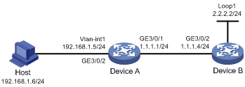
Exporting NAT logs to the information center
Network requirements
· A host in the private network accesses Device B in the public network through Device A, which is enabled with NAT.
· Device A sends NAT logs to the information center in the form of system logs.
· You can view the records on the information center to supervise the private network users.
Configuration procedure
The following only lists configurations pertinent to NAT logs.
Details of configurations regarding the IP addresses of the switches and NAT function are not shown.
# Specify IP addresses for the interfaces, as shown in Figure 10. (Details not shown.)
# Export the NAT logs of Device A to the information center.
<DeviceA> system-view
[DeviceA] userlog nat syslog
# Enable the NAT log function on Device A.
[DeviceA] nat log enable
# View the log buffer to monitor access records.
[DeviceA] quit
<DeviceA> dir
Directory of cf:/
0 -rw- 16850028 Aug 07 2009 04:02:42 mainpack.bin
1 drw- - Aug 07 2005 05:13:48 logfile
2 -rw- 1747 Aug 07 2009 04:05:38 vrpcfg.cfg
3 -rw- 524288 Aug 13 2009 01:27:40 basicbtm.bin
4 -rw- 524288 Aug 13 2009 01:27:40 extendbtm.bin
249852 KB total (232072 KB free)
File system type of cf: FAT32
<DeviceA> cd logfile
<DeviceA> more logfile.log
…
%@250005%Jul 7 04:20:04:72 2005 DeviceA USERLOG/7/NAT:
ICMP; 192.168.1.6:768--->1.1.1.1:12288; 2.2.2.2:768;
[2005/07/07 04:20:03-0000/00/00 00:00:00];
Operator 8: Data flow created
%@250006%Jul 7 04:20:10:72 2005 DeviceA USERLOG/7/NAT:
ICMP; 192.168.1.6:768--->1.1.1.1:12288; 2.2.2.2:768;
[2005/07/07 04:20:03-2005/07/07 04:20:09];
Operator 1: Normal over
%@250007%Jul 7 04:20:30:72 2005 DeviceA USERLOG/7/NAT:
ICMP; 192.168.1.6:768--->1.1.1.1:12288; 2.2.2.2:768;
[2005/07/07 04:20:29-0000/00/00 00:00:00];
Operator 8: Data flow created
…
Apart from NAT logs, the log file includes other system logs, as described in Table 1.
Table 1 Description on NAT logs
|
Field |
Description |
|
ICMP |
ICMP. |
|
192.168.1.6:768 |
Source IP address and port number before translation. |
|
1.1.1.1:12288 |
Source IP address and port number after translation. |
|
2.2.2.2:768 |
Destination IP address and port number. |
|
2005/07/07 04:20:03 2005/07/07 04:20:29 |
Start time of the NAT session. In this example, the time displayed is the switch's system time. When the logs are exported in UDP packet, the UDP packet records the interval in seconds between the current system time and Greenwich time 0 AM, Jan 1st, 1970. The log server, based on its own system time, converts this interval and exports it. |
|
2005/07/07 04:20:09 0000/00/00 00:00:00 |
End time of the NAT session. 0000/00/00 00:00:00 means that this time is uncertain. |
|
Operator |
Reasons for generating NAT logs come from: · Aged for reset or config-change refers to logs generated due to configuration change or manual session deletion. · Aged for no-pat of NAT refers to logs generated when the no-pat session is aged out. · Active data flow timeout refers to logs generated when the duration of NAT session exceeds the active data flow time. · Data flow created refers to logs generated when a NAT session is established. · Normal over refers to logs generated when the session is aged out. |
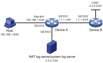
Exporting NAT logs to log server
Network requirements
· A PC in the private network accesses Device B on the public network through Device A, which is enabled with NAT.
· Device A sends NAT logs to the information center in UDP packets.
Configuration procedure
The following only lists configurations pertinent to NAT logs.
Details of configurations regarding the IP addresses of the switches and NAT function are not shown.
# Specify IP addresses for the interfaces, as shown in Figure 11. (Details not shown.)
# Export the NAT logs of Device A to the NAT log server.
<DeviceA> system-view
[DeviceA] userlog nat export host 3.3.3.7 9021
# Set the source IP address of NAT log packets for Device A to 9.9.9.9.
[DeviceA] userlog nat export source-ip 9.9.9.9
# Enable the NAT log function on Device A.
[DeviceA] nat log enable
You must run XLog on the NAT log server or the system log server to view NAT log information.
Troubleshooting NAT
Symptom 1
Abnormal translation of IP addresses.
Solution
1. Enable debugging for NAT. Try to locate the problem based on the debugging display.
2. Use other commands, if necessary, to further identify the problem. Pay special attention to the source address after the address translation and make sure this address is the address that you intend to change to. If not, there might be an address pool bug.
3. Ensure a route is available between the destination network and the address pool segment.
4. Be aware of the possible effects that the firewall or the ACLs have on NAT, and note the route configurations.
Symptom 2
Internal server does not function correctly.
Solution
1. Check whether the internal server host is correctly configured.
2. Check whether the router is correctly configured with respect to the internal server parameters, such as the internal server IP address.
3. Use the display acl command to verify whether the firewall has denied external access to the internal network.