- Table of Contents
-
- H3C S3100-52P Ethernet Switch Operation Manual-Release 1500(V1.02)
- 00-1Cover
- 00-2Overview
- 01-CLI Operation
- 02-Login Operation
- 03-Configuration File Management Operation
- 04-VLAN Operation
- 05-IP Address and Performance Confiugration Operation
- 06-GVRP Operation
- 07-Port Basic Configuration Operation
- 08-Link Aggregation Operation
- 09-Port Isolation Operation
- 10-DLDP Operation
- 11-MAC Address Table Operation
- 12-MSTP Operation
- 13-Multicast Operation
- 14-Routing Protocol Operation
- 15-802.1x Operation
- 16-AAA-RADIUS-HWTACACS Operation
- 17-Centralized MAC Address Authentication Operation
- 18-DHCP Operation
- 19-ARP Operation
- 20-ACL Operation
- 21-QoS Operation
- 22-Mirroring Operation
- 23-Cluster Operation
- 24-SNMP and RMON Operation
- 25-NTP Operation
- 26-SSH Terminal Service Operation
- 27-File System Management Operation
- 28-FTP and TFTP Operatio
- 29-Information Center Operation
- 30-System Maintenance and Debugging Operation
- 31-VLAN VPN Operation
- 32-HWPing Operation
- 33-DNS Operation
- 34-Appendix
- Related Documents
-
| Title | Size | Download |
|---|---|---|
| 21-QoS Operation | 542.95 KB |
Table of Contents
1.1.4 Priority of Protocol Packets
1.1.6 Queue Scheduling Configuration Synchronization on Aggregated Ports
1.2 QoS Supported by S3100-52P
1.3 Configuring the Mapping between 802.1p Priority and Queues
1.4 Setting to Use the Port Priority or Packet Priority
1.5 Setting the Precedence of Protocol Packet
1.5.1 Configuration Prerequisites
1.6 Configuring Port Rate Limit
1.6.1 Configuration Prerequisites
1.7 Configuring Queue-Scheduling
1.7.1 Configuration Prerequisites
1.8 Displaying QOS Configuration
Chapter 1 QoS Configuration
1.1 Overview
QoS (Quality of Service) is a concept generally existing in occasions with service supply and demand. It evaluates the ability to meet the need of the customers in service. Generally, the evaluation is not to grade precisely. Its purpose is to analyze the conditions where the service is the best and the conditions where the service still needs improvement and then to make improvements in the specified aspects.
1.1.1 Traffic
Traffic means service traffic; that is, all the packets passing the switch.
1.1.2 Traffic Classification
Traffic classification means identifying packets that conform to certain characteristics according to certain rules.
A classification rule is a filter rule configured to meet your management requirements. It can be very simple. For example, you can use a classification rule to identify traffic with different priorities according to the ToS field in the IP packet header. It can be very complicated too. For example, you can use a classification rule to identify the packets according to the combination of link layer (Layer 2), network layer (Layer 3), and transport layer (Layer 4) information including MAC addresses, IP protocols, source addresses, destination addresses, port numbers of applications, and so on.
1.1.3 Precedence
1) IP precedence, ToS precedence, and DSCP precedence

Figure 1-1 DS field and TOS byte
The TOS field in an IP header contains eight bits:
l The first three bits indicate IP precedence in the range of 0 to 7.
l Bit 3 to bit 6 indicate ToS precedence in the range of 0 to 15.
l RFC2474 re-defines the ToS field in the IP packet header, which is called the DS field. The first six (bit 0 to bit 5) bits of the DS field indicate DSCP precedence in the range of 0 to 63. The first three bits in DSCP precedence are class selector codepoints, bit 4 and bit 5 indicate drop precedence, and bit 6 is zero indicating that the device sets the service class with the DS model. The last two bits (bit 6 and bit 7) are reserved bits.
The precedence values of the IP packet indicate eight different service classes.
Table 1-1 Description on IP Precedence
|
IP Precedence (decimal) |
IP Precedence (binary) |
Description |
|
0 |
000 |
routine |
|
1 |
001 |
priority |
|
2 |
010 |
immediate |
|
3 |
011 |
flash |
|
4 |
100 |
flash-override |
|
5 |
101 |
critical |
|
6 |
110 |
internet |
|
7 |
111 |
network |
The Diff-Serv network defines four traffic classes:
l Expedited Forwarding (EF) class: In this class, packets can be forwarded regardless of link share of other traffic. The class is suitable for preferential services with low delay, low packet loss ratio, low jitter, and assured bandwidth (such as virtual leased line);
l Assured forwarding (AF) class: This class is further divided into four subclasses (AF1/2/3/4) and a subclass is further divided into three drop priorities, so the AF service level can be segmented. The QoS rank of the AF class is lower than that of the EF class;
l Class selector (CS) class: This class comes from the IP TOS field and includes eight classes;
Table 1-2 Description on DSCP values
|
DSCP value (decimal) |
DSCP value (binary) |
Description |
|
46 |
101110 |
ef |
|
10 |
001010 |
af11 |
|
12 |
001100 |
af12 |
|
14 |
001110 |
af13 |
|
18 |
010010 |
af21 |
|
20 |
010100 |
af22 |
|
22 |
010110 |
af23 |
|
26 |
011010 |
af31 |
|
28 |
011100 |
af32 |
|
30 |
011110 |
af33 |
|
34 |
100010 |
af41 |
|
36 |
100100 |
af42 |
|
38 |
100110 |
af43 |
|
8 |
001000 |
cs1 |
|
16 |
010000 |
cs2 |
|
24 |
011000 |
cs3 |
|
32 |
100000 |
cs4 |
|
40 |
101000 |
cs5 |
|
48 |
110000 |
cs6 |
|
56 |
111000 |
cs7 |
|
0 |
000000 |
default (be) |
802.1p priority lies in Layer 2 packet headers and is applicable to occasions where the Layer 3 packet header does not need analysis but QoS must be assured at Layer 2.

Figure 1-2 An Ethernet frame with an 802.1Q tag header
As shown in the figure above, each host supporting 802.1Q protocol adds a 4-byte 802.1Q tag header after the source address of the former Ethernet frame header when sending packets.
The 4-byte 802.1Q tag header contains a 2-byte Tag Protocol Identifier (TPID) whose value is 8100 and a 2-byte Tag Control Information (TCI). TPID is a new class defined by IEEE to indicate a packet with an 802.1Q tag. Figure 1-3 describes the detailed contents of an 802.1Q tag header.

In the figure above, the 3-bit priority field in TCI is 802.1p priority in the range of 0 to 7. These three bits specify the precedence of the frame. Eight classes of precedence are used to determine which packet is sent preferentially when congestion occurs.
Table 1-3 Description on 802.1p priority
|
CoS (decimal) |
CoS (binary) |
Description |
|
0 |
000 |
best-effort |
|
1 |
001 |
background |
|
2 |
010 |
spare |
|
3 |
011 |
excellent-effort |
|
4 |
100 |
controlled-load |
|
5 |
101 |
video |
|
6 |
110 |
voice |
|
7 |
111 |
network-management |
The precedence is called 802.1p priority because the related applications of this precedence are defined in detail in the 802.1p specifications.
1.1.4 Priority of Protocol Packets
Protocol packets carry their own priority. You can perform QoS actions on protocol packets by setting their priorities.
1.1.5 Port Rate Limit
Port rate limit is port-based rate limit. It limits the total rate of outbound packets on a port.
1.1.6 Queue Scheduling Configuration Synchronization on Aggregated Ports
The feature of queue scheduling configuration synchronization on aggregated ports makes the queue scheduling configuration synchronous on each port of an aggregation group.
l Supporting the feature of queue scheduling configuration synchronization on the ports in an aggregation group
When you modify or delete the queue scheduling mode in Ethernet port view, the queue scheduling modes of all the ports in the aggregation group are modified or deleted if this port belongs to an aggregation group; only the queue scheduling mode of this port is modified or deleted if this port does not belong to any aggregation group.
l Dynamic aggregation supported by queue scheduling modes on ports
If the queue scheduling configuration information of some LACP-enabled ports in up state is the same, these ports can be aggregated into the same aggregation group.
l Static aggregation or manual aggregation supported by queue scheduling modes on ports
You can add a queue-scheduling-enabled port into a specific static or manual aggregation group. This operation can be performed not only on the local device but also across devices in an intelligent resilient framework (IRF).
l You can use the copy command to copy the queue scheduling configuration of a port.
& Note:
For the introduction to the copy command, refer to the Basic Port Configuration Module in this manual.
1.1.7 Queue Scheduling
When the network is congested, the problem that many packets compete for resources must be solved, usually through queue scheduling.
1) SP queueing

Figure 1-4 Diagram for SP queueing
SP queue-scheduling algorithm is specially designed for critical service applications. An important feature of critical services is that they demand preferential service in congestion in order to reduce the response delay. Assume that there are eight output queues on the port and the preferential queue classifies the eight output queues on the port into eight classes, which are queue7, queue6, queue5, queue4, queue3, queue2, queue1, and queue0. Their priorities decrease in order.
In queue scheduling, SP sends packets in the queue with higher priority strictly following the priority order from high to low. When the queue with higher priority is empty, packets in the queue with lower priority are sent. You can put critical service packets into the queues with higher priority and put non-critical service (such as e-mail) packets into the queues with lower priority. In this case, critical service packets are sent preferentially and non-critical service packets are sent when critical service groups are not sent.
2) WRR queueing
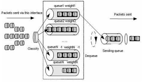
WRR queue-scheduling algorithm schedules all the queues in turn and every queue can be assured of a certain service time. Assume there are eight priority queues on a port. WRR configures a weight value for each queue, which is w7, w6, w5, w4, w3, w2, w1, and w0. The weight value indicates the proportion of obtaining resources. On a 100 M port, configure the weight value of WRR queue-scheduling algorithm to 50, 50, 30, 30, 10, 10, 10, and 10 (corresponding to w7, w6, w5, w4, w3, w2, w1, and w0 in order). In this way, the queue with the lowest priority can get 5 Mbps bandwidth at least, and the disadvantage of SP queue-scheduling that the packets in queues with lower priority may not get service for a long time is avoided. Another advantage of WRR queue is that: though the queues are scheduled in order, the service time for each queue is not fixed; that is to say, if a queue is empty, the next queue will be scheduled. In this way, the bandwidth resources are made full use.
1.2 QoS Supported by S3100-52P
Table 1-4 QoS functions supported by S3100-52P and related commands
|
QoS |
Specification |
Related command |
|
Priority mapping |
Support only the mapping between 802.1p priority and local queues |
qos cos-local-precedence-map |
|
Port priority |
Supported |
priority priority-level priority trust |
|
Queue scheduling |
Support SP and WRR Support queue scheduling configuration synchronization on aggregated ports |
queue-scheduler |
|
Set the priority of protocol packets |
Supported |
protocol-priority |
|
Set port rate limit |
Supported |
line-rate |
1.3 Configuring the Mapping between 802.1p Priority and Queues
The mapping between the local precedence and the outbound queue is one-to-one. You can modify the mapping between the 802.1p priority and the outbound queue by modifying the mapping between the 802.1p priority and the local precedence.
I. Configuration prerequisites
You have understood the mapping between the 802.1p priority and the local precedence and the default mapping table.
II. Configuration procedure
Table 1-5 Configure the mapping table
|
Operation |
Command |
Description |
|
Enter system view |
system-view |
— |
|
Configure the COS-to-local-precedence mapping table |
qos cos-local-precedence-map cos0-map-local-prec cos1-map-local-prec cos2-map-local-prec cos3-map-local-prec cos4-map-local-prec cos5-map-local-prec cos6-map-local-prec cos7-map-local-prec |
Optional |
|
Display the mapping table |
display qos cos-local-precedence-map |
Optional You can execute the display command in any view |
III. Configuration example
l Configure the following 802.1p priority-to-local precedence mappings: 0 to 2, 1 to 3, 2 to 4, 3 to 1, 4 to 7, 5 to 0, 6 to 5, and 7 to 6.
l Display the configuration results.
Configuration procedure:
<H3C> system-view
System View: return to User View with Ctrl+Z.
[H3C] qos cos-local-precedence-map 2 3 4 1 7 0 5 6
[H3C] dis qos cos-local-precedence-map
cos-local-precedence-map:
cos(802.1p) : 0 1 2 3 4 5 6 7
--------------------------------------------------------------------------
local precedence(queue) : 2 3 4 1 7 0 5 6
1.4 Setting to Use the Port Priority or Packet Priority
In addition, you can specify the switch to use the packet priority.
I. Configuration prerequisites
l The priority trust mode is specified
l The port whose priority is to be configured is specified
l The priority value of the specified port is specified
II. Configuration procedure
Table 1-6 Set to use the port priority
|
Operation |
Command |
Description |
|
Enter system view |
system-view |
— |
|
Enter Ethernet port view |
interface interface-type interface-number |
— |
|
Set the port priority |
priority priority-level |
Optional By default, the port priority is 0 |
Table 1-7 Set to use the packet priority
|
Operation |
Command |
Description |
|
Enter system view |
system-view |
— |
|
Enter Ethernet port view |
interface interface-type interface-number |
— |
|
Set the switch to use the packet priority |
priority trust |
Through this configuration, the switch uses the packet priority instead of the port priority |
III. Configuration example
l Set to use the port priority and specify the priority of Ethernet1/0/1 to 7.
Configuration procedure:
<H3C> system-view
System View: return to User View with Ctrl+Z.
[H3C] interface Ethernet1/0/1
[H3C-Ethernet1/0/1] undo priority
[H3C-Ethernet1/0/1] priority 7
l Set the switch to use the 802.1p priority carried in the packet on Ethernet1/0/1.
Configuration procedure:
<H3C> system-view
System View: return to User View with Ctrl+Z.
[H3C] interface Ethernet1/0/1
[H3C-Ethernet1/0/1] priority trust
1.5 Setting the Precedence of Protocol Packet
The protocol packet carries its own precedence. You can modify the precedence of the protocol packet by setting its precedence. And then you can match the precedence with the corresponding QoS action to perform the corresponding QoS operation on the protocol packet.
1.5.1 Configuration Prerequisites
l The type of protocol whose precedence needs modification is specified
l The precedence value after modification is specified
1.5.2 Configuration Procedure
Table 1-8 Set the precedence of the protocol packet
|
Operation |
Command |
Description |
|
Enter system view |
system-view |
— |
|
Set the precedence of the protocol packet |
protocol-priority protocol-type protocol-type { ip-precedence ip-precedence | dscp dscp-value } |
Required You can modify the IP precedence or DSCP precedence of the protocol packet Only the precedence of TELNET, OSPF, SNMP, and ICMP protocol packets is supported currently |
|
Display the precedence of the protocol packet |
display protocol-priority |
Optional You can execute the display command in any view |
1.5.3 Configuration Example
l Set the IP precedence of ICMP protocol packets to 3.
l Display the configuration results.
Configuration procedure:
<H3C> system-view
System View: return to User View with Ctrl+Z.
[H3C] protocol-priority protocol-type icmp ip-precedence 3
[H3C] display protocol-priority
Protocol: icmp
IP-Precedence: flash(3)
1.6 Configuring Port Rate Limit
1.6.1 Configuration Prerequisites
l The ports on which rate limit is to be performed is specified
l The target rate is specified
l The direction of rate limit is specified
1.6.2 Configuration Procedure
Table 1-9 Configure port rate limit
|
Operation |
Command |
Description |
|
Enter system view |
system-view |
— |
|
Enter Ethernet port view |
interface interface-type interface-number |
— |
|
Configure port-based rate limit |
line-rate { inbound | outbound } target-rate |
Required l target-rate: Total rate to limit packet sending and receiving on the port, in Kbps. The granularity of rate limit is 64 Kbps. If the number you input is in the range of N*64 to (N+1)*64 (N is a natural number), the switch will set the value to (N+1)*64 Kbps automatically l The rate range of 100 M Ethernet ports is from 64 to 99,968 l The rate range of Gigabit Ethernet ports is in from 64 to 1,000,000 |
1.6.3 Configuration Example
l Set rate limit in the outbound direction of Ethernet1/0/1 on the switch
l The limit rate is 1 Mbps (1,024 Kbps)
Configuration procedure:
<H3C> system-view
System View: return to User View with Ctrl+Z.
[H3C] interface Ethernet1/0/1
[H3C-Ethernet1/0/1] line-rate outbound 1024
1.7 Configuring Queue-Scheduling
Refer to section 1.1.7 "Queue Scheduling" for the introduction to queue scheduling.
1.7.1 Configuration Prerequisites
The queue-scheduling algorithm is specified: which queues adopt the WRR queue-scheduling algorithm, and which queues adopt the SP queue-scheduling algorithm.
1.7.2 Configuration Procedure
Table 1-10 Configure queue scheduling in system view
|
Operation |
Command |
Description |
|
Enter system view |
system-view |
— |
|
Configure the queue scheduling mode |
queue-scheduler { strict-priority | wrr queue0-weight queue1-weight queue2-weight queue3-weight queue4-weight queue5-weight queue6-weight queue7-weight } |
Required In WRR mode, if the weight value of one or more queues is set to 0, SP algorithm is used for this or these queues By default, all the outbound queues on the port adopt the WRR queue scheduling algorithm and their default weight values are 1:2:3:4:5:9:13:15. |
|
Display the queue-scheduling mode and related parameters on the switch |
display queue-scheduler |
Optional You can execute the display command in any view. |
Table 1-11 Configure queue scheduling in Ethernet port view
|
Operation |
Command |
Description |
|
Enter system view |
system-view |
— |
|
Enter Ethernet port view |
interface interface-type interface-number |
— |
|
Configure the queue scheduling mode |
queue-scheduler wrr queue0-weight queue1-weight queue2-weight queue3-weight queue4-weight queue5-weight queue6-weight queue7-weight |
Required In WRR mode, if the weight value of one or more queues is set to 0, SP algorithm is used for this or these queues By default, all the outbound queues on the port adopt the WRR queue scheduling algorithm and their default weight values are 1:2:3:4:5:9:13:15. |
& Note:
l The queue scheduling algorithm defined by executing the queue-scheduler command in system view takes effect on all ports of the switch. The queue scheduling algorithm defined by executing the queue-scheduler command in Ethernet port view takes effect on the current port only. If the weight values of the queues in the WRR queue scheduling algorithm defined globally cannot satisfy the requirement of a port, you can modify the weight values of the queues in Ethernet port view of this port. A new queue scheduling algorithm on this port will overwrite the globally defined queue weight value. You cannot use the display queue-scheduler command to display the queue weight defined in Ethernet port view.
l If you have configured link aggregation groups, the queue scheduling algorithm defined on a port in an aggregation group will be synchronized to other ports in the aggregation group automatically.
1.7.3 Configuration Example
l The switch adopts the WRR queue scheduling algorithm, and the weight values of outbound queues are 2, 2, 3, 3, 4, 4, 5, and 5, respectively;
l Disable the applied queue scheduling mode. By default, all outbound queues on the port adopts the WRR queue scheduling algorithm and their default weight values are 1:2:3:4:5:9:13:15;
l Query the configuration information.
Configuration procedure:
<H3C> system-view
System View: return to User View with Ctrl+Z.
[H3C] queue-scheduler wrr 2 2 3 3 4 4 5 5
[H3C]display queue-scheduler
Queue scheduling mode: weighted round robin
weight of queue 0: 2
weight of queue 1: 2
weight of queue 2: 3
weight of queue 3: 3
weight of queue 4: 4
weight of queue 5: 4
weight of queue 6: 5
weight of queue 7: 5
[H3C] undo queue-scheduler
[H3C] display queue-scheduler
weight of queue 0: 1
weight of queue 1: 2
weight of queue 2: 3
weight of queue 3: 4
weight of queue 4: 5
weight of queue 5: 9
weight of queue 6: 13
weight of queue 7: 15
1.8 Displaying QOS Configuration
Table 1-12 Display the QoS configuration
|
Operation |
Command |
Description |
|
Display the configuration of protocol packet precedence |
display protocol-priority |
You can execute the display command in any view |
|
Display the Mapping between 802.1p Priority and Queues |
display qos cos-local-precedence-map |
|
|
Display all QoS configurations on a port or all ports |
display qos-interface {interface-type interface-number | unit-id } all |
|
|
Display the rate limit configuration |
display qos-interface { interface-type interface-number | unit-id } line-rate |
|
|
Display the global queue scheduling configuration |
display queue-scheduler |