- Table of Contents
- Related Documents
-
| Title | Size | Download |
|---|---|---|
| 01-WLAN Service Configuration | 836.69 KB |
Table of Contents
Enabling WLAN Service (only supported on ACs)
Configuring Global WLAN Parameters (only supported on fat APs)
Specifying the uplink interface (only supported on fat APs)
Configuring Software Version Automatic Update
Configuring a WLAN Service Template
Configuring an AP (only supported on ACs)
Configuring CAPWAP Dual-Link (Supported only on ACs)
Configuring the Radio of an AP
Configuring a Radio Policy on an AC or the Radio of a Fat AP
Displaying and Maintaining WLAN Service
Configuring AP Group (only supported on ACs)
Applying the AP Group in a User Profile
Displaying and Maintaining AP Group·
Configuring SSID-Based Access Control
Specifying a Permitted SSID in a User Profile
WLAN Service Configuration Examples
WLAN Service Configuration Example (On an AC)
WLAN Auto-AP Configuration Example (On an AC)
CAPWAP Dual-Link Configuration Example (On an AC)
WLAN Service Configuration Example (on a FAT AP)
AP Group Configuration Examples
AP Group Configuration without Roaming
AP Group Configuration for Inter-AC Roaming
![]()
l Support for some features varies by router model.
l Refer to the command manual of this module for command and parameter support, default values and value ranges of the MSR series routers.
l All the models of the MSR series routers are centralized devices.
l The MSR series routers can serve as APs only.
When configuring WLAN service, go to these sections for information you are interested in:
l Configuring AP Group (only supported on ACs)
l Configuring SSID-Based Access Control
l WLAN Service Configuration Examples
l AP Group Configuration Examples
WLAN Service Overview
Wireless Local Area Networks (WLAN) have become very popular because they are very easy to setup and use, and have low maintenance cost. Generally, one or more access points (APs) can cover a building or an area. A WLAN is not completely wireless because the servers in the backbone are fixed.
The WLAN solution allows you to provide the following wireless LAN services to your customers:
l WLAN client connectivity to conventional 802.3 LANs
l Secured WLAN access with different authentication and encryption methods
l Seamless roaming of WLAN clients in the mobility domain
Terminology
Client
A handheld computer or laptop with a wireless Network Interface Card (NIC) can be a WLAN client.
Access point (AP)
An AP bridges frames between wireless and wired networks.
Access controller (AC)
An AC can control and manage all APs in a WLAN. The AC communicates with an authentication server for WLAN client authentication.
Fat AP
A fat AP controls and manages all associated wireless stations and bridges frames between wired and wireless networks.
SSID
Service set identifier. A client scans all networks at first, and then selects a specific SSID to connect to a specific wireless network.
Wireless medium
A medium that is used for transmitting frames between wireless clients. Radio frequency is used as the wireless medium in the WLAN system.
Distribution system
A distribution system is used to forward frames to their destinations. It is the backbone to transmit frames between access points.
Split MAC
In split MAC mode, APs and ACs manage different services. An AP manages real-time services, such as beacon generation, power management, fragmentation and defragmentation. An AC manages services related to packet distribution, association, dissociation and reassociation.
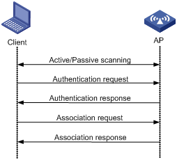
Client Access
A client access process involves three steps: active/passive scanning, authentication and association.
Figure 1-1 Establish a client access
Scanning
1) Active scanning
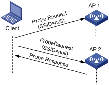
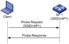
Active scanning is used by clients to scan surrounding wireless networks and locate a compatible one. Active scanning falls into two modes according to whether a specified SSID is carried in a probe request.
l A client sends a probe request (with the SSID null): The client prepares a list of channels and broadcasts a probe request frame on each of them. APs that receive the probe request send a probe response. The client associates with the AP with the strongest signal. This active scanning mode enables a client to know whether an AP can provide wireless services.
Figure 1-2 Active scanning (the SSID of the probe request is null)
l A client sends a probe request (with a specified SSID): In this case, the client only unicasts a probe request because the probe request it sends carries the specified SSID. When an AP receives the probe request, it sends a probe response. This active scanning mode enables a client to access a specified wireless network.
Figure 1-3 Active scanning (the probe request carries the specified SSID)
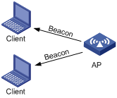
2) Passive scanning
Passive scanning is used by clients to discover surrounding wireless networks through listening to the beacon frames periodically sent by an AP. The client prepares a list of channels and listens to beacons on each of these channels. In this case, the AP needs to periodically broadcast beacon frames. Passive scanning is used by a client when it wants to save battery power. Typically, VoIP clients adopt the passive scanning mode.
Figure 1-4 Passive scanning
Authentication
To prevent illegal clients from accessing a network, authentication is needed between clients and ACs or between clients and fat APs. There are two types of authentication:
l Open system authentication
l Shared key authentication
For details about the two types of authentication, refer to WLAN Security Configuration in the WLAN Volume.
Association
A client that wants to access a wireless network via an AP must be associated with that AP. Once the client chooses a compatible network with a specified SSID and authenticates to an AP, it sends an association request frame to the AP. The AP sends an association response to the client and adds the client’s information in its database. At a time, a client can associate with only one AP. An association process is always initiated by the client, but not by the AP.
Other related frames
1) De-authentication
An AC or a fat AP sends a de-authentication frame to remove a client from the wireless system. De-authentication can occur due to many reasons, such as:
l Receiving an association/disassociation frame from a client which is unauthenticated.
l Receiving a data frame from a client which is unauthenticated.
l Receiving a PS-poll frame from a client which is unauthenticated.
l The validity timer for a client expires and the port is not secured.
2) Dissociation
A client sends a dissociation frame to an AP to end the association between them. Dissociation can occur due to many reasons, such as:
l Receiving a data frame from a client which is authenticated and unassociated.
l Receiving a PS-Poll frame from a client which is authenticated and unassociated.
A dissociation frame is either unicast or broadcast.
3) Re-association
When a client is roaming from one AP to another AP, it sends a re-association request to the new AP. The AP relays this re-association request to the AC. The AC then informs the previous AP to delete the client’s information from its database, informs the new AP to add the client’s information in its database and conveys successful re-association information to the client.
When a client leaves the coverage of an AP, and then needs to re-join the AP, it must re-associate with the AP.
802.11 Overview
The WLAN-MAC primarily includes the implementation of IEEE 802.11 MAC layer functionality. Various modes of MAC are:
l Local-MAC Architecture
l Split-MAC Architecture
In local-MAC architecture, most WLAN services are provided by the AP only. Currently, local-MAC architecture is not supported.
In split-MAC architecture, the AP and the AC manage different services.
CAPWAP Overview
Introduction to CAPWAP
Control And Provisioning of Wireless Access Points (CAPWAP) defines how an AP communicates with an AC. It provides a generic encapsulation and transport mechanism between AP and AC, as shown in Figure 1-5.
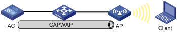
CAPWAP runs on an AP and an AC to provide a secured connection in between. It is built on a standard client/server model and employs UDP.
On an AP, CAPWAP provides a data tunnel to encapsulate data packets to be sent to the AC. These packets can be raw 802.11 packets or 802.11 to 802.3 translated packets. On an AC, CAPWAP provides a control tunnel to support remote AP configuration and management, and WLAN and mobile management.
With CAPWAP, the AC can dynamically configure an AP based on the information provided by the administrator.
CAPWAP supports both IPv4 and IPv6.
CAPWAP Link Backup
Dual link establishment
To achieve AC backup, an AP can establish two tunnels with two ACs that must have the same AP configurations. Only the AC which works in master mode provides services to all the APs in the network and the slave AC acts as the backup AC. If the master AC fails, APs should quickly use the services provided by the slave AC. A heartbeat mechanism is used between these two ACs, which ensures that failure of the master will be detected quickly by the backup AC.
Figure 1-6 LWAPP dual link topology
In the above figure, AC1 is working in master mode and providing services to AP1, AP2, AP3 and AP4. AC2 is working in slave mode. APs are connected to AC2 through LWAPP slave tunnels. AC1 and AC2 can be configured as backup for each other and should start master/slave detection. When AC2 detects AC1 is down, AC2 will convert the work mode from slave to master. All APs which are connected to AC2 through slave tunnels will transform the tunnels to master tunnels and use AC2 as the master AC. Once AC 1 is reachable again, it will remain the backup.
Primary AC recovery
Figure 1-7 Primary AC recovery
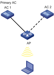
In the above figure, AC 1 acting as the primary AC is the master (which has the connection priority of 7), and it establishes a CAPWAP connection with the AP; AC 2 acts as the slave AC. If AC 1 goes down, AC 2 will act as the master until recovery of the CAPWAP. This means once AC 1 is reachable again, the AP will establish a connection with AC 1 acting as the primary AC and disconnect from AC 2.
Dual work mode
Figure 1-8 Dual work mode
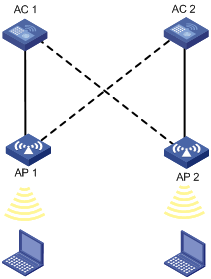
Dual work mode indicates that an AC can provide both master and slave connections. An AC will act as the master for some APs and act as the slave for some other APs. In the above scenario, AC 1 acts as the master for AP 1 and slave for AP 2. Similarly, AC 2 acts as the master for AP 2 and slave for AP 1.
WLAN Topologies
WLAN Topologies for ACs
WLAN topologies for ACs consist of:
l Single BSS
l Multi-ESS
l VLAN-based WLAN
l Centralized WLAN
Single BSS
The coverage of an AP is called a basic service set (BSS). Each BSS is identified by a BSSID. The most basic WLAN network can be established with only one BSS. All wireless clients associate with the same BSS. If these clients have the same authorization, they can communicate with each other. Figure 1-9 shows a single-BSS WLAN.
Figure 1-9 Single BSS network
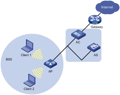
The clients can communicate with each other and reach a host in the Internet. Communications between clients within the same BSS are carried out through the AP and the AC.
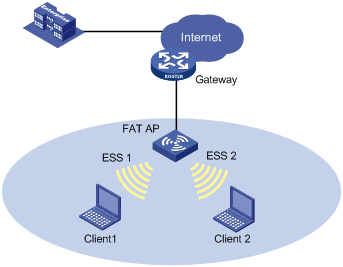
Muti-ESS
All the clients under the same logical administration form an extended service set (ESS). This multi-ESS topology describes a scenario where more than one ESS exists. When a mobile client joins the AP, it can join one of the available ESSs. Figure 1-10 shows a multi-ESS network.
Figure 1-10 Multi-ESS network
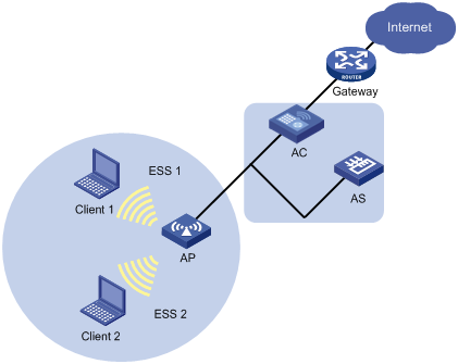
Generally, an AP can provide more than one ESS at the same time. The configuration of ESS is distributed mainly from AC to AP, and the AP can broadcast the current information of ESS by beacon or probe response frames. Clients can select an ESS it is interested to join.
Different ESS domains can be configured on the AC. The AC can be configured to allow associated APs to accept clients in these ESS domains once their credentials are accepted.
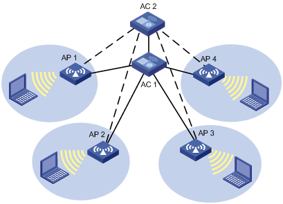
Centralized WLAN
Centralized WLAN is a unified solution for wireless local area networks. Figure 1-11 shows a centralized WLAN network.
Figure 1-11 Centralized WLAN network
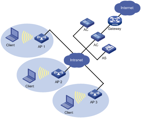
In this network, there are two ACs and three APs. An AP can connect with an AC directly, or over a Layer 2 or Layer 3 network. The other AC serves as the backup.
During initialization, an AP obtains its basic network configuration parameters, such as its own IP address, gateway address, domain name and DNS server address from a DHCP server.
An AP uses a discovery mechanism to locate the AC. For example, using the unicast discovery mechanism, the AP can request the DNS server to provide the IP address of the AC.
The following describes a basic communication process in the centralized WLAN network.
1) A client gets associated with an AP in the network.
2) The AP communicates with the AC for authenticating the client’s credential.
3) The AC contacts the authentication server to authenticate the client.
4) Once the wireless client passes authentication, it can access authorized WLAN services and communicate with other wireless clients or wired devices.
WLAN Topologies for Fat APs
WLAN topologies for fat APs consist of:
l Single BSS
l Multi-ESS
l Single ESS Multi-BSS
Single BSS
The coverage of an AP is called a basic service set (BSS). Each BSS is identified by a BSSID. The most basic WLAN network can be established with only one BSS. All wireless clients associate with the same BSS. If these clients have the same authorization, they can communicate with each other. Figure 1-12 shows a single BSS network.
Figure 1-12 Single BSS network
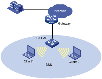
The clients can communicate with each other or reach a host in the Internet. Communications between clients within the same BSS are carried out through the fat AP.
Muti-ESS
This topology describes a scenario where more than one ESS exists. When a mobile client joins the fat AP, it can join one of the available ESSs. Figure 1-13 shows a multi-ESS network.
Generally a fat AP can provide more than one logical ESS at the same time. The fat AP can broadcast the current information of ESS by beacon or probe response frames. Clients can select an ESS it is interested to join.
Different ESS domains can be configured on the fat AP. The fat AP can be configured to accept clients in these ESS domains once their credentials are acceptable.
Single ESS Muti-BSS (The multi-radio case)
This topology describes a scenario where a fat AP has two radios that are in the same ESS but belong to different BSSs.
Figure 1-14 Single ESS Multiple BSS network

This network scenario can be used when both 802.11a and 802.11b/g need to be supported. Figure 1-14 shows two clients connected to different radios belong to the same ESS but different BSSs.
Protocols and Standards
l ANSI/IEEE Std 802.11, 1999 Edition
l IEEE Std 802.11a
l IEEE Std 802.11b
l IEEE Std 802.11g
l IEEE Std 802.11i
l IEEE Std 802.11-2004
Configuring WLAN Service
Configuration Task List
|
Task |
Description |
|
Required |
|
|
Configuring Global WLAN Parameters (only supported on fat APs) |
Optional |
|
Optional |
|
|
Required |
|
|
Optional |
|
|
Required |
|
|
Required |
|
|
Optional |
|
|
Optional |
|
|
Required |
|
|
Configuring a Radio Policy on an AC or the Radio of a Fat AP |
Required |
|
Optional |
Enabling WLAN Service (only supported on ACs)
WLAN service is a component of the Comware platform, and can be enabled or disabled at runtime.
Follow these steps to enable WLAN service:
|
To do… |
Use the command… |
Remarks |
|
Enter system view |
system-view |
— |
|
Enable WLAN service |
wlan enable |
By default, WLAN service is enabled and “WLAN service enabled” is displayed. |
Configuring Global WLAN Parameters (only supported on fat APs)
Follow these steps to configure global WLAN parameters:
|
To do… |
Use the command… |
Remarks |
|
Enter system view |
system-view |
— |
|
Configure the client idle timeout interval for the fat AP |
wlan client idle-timeout interval |
Optional By default, the idle timeout interval is 3600 seconds. |
|
Configure the keep alive interval for the fat AP |
wlan client keep-alive interval |
Optional By default, keep–alive function is disabled. |
|
Enable the fat AP to respond to broadcast probe requests |
wlan broadcast–probe reply |
Optional Enabled by default. |
Specifying the uplink interface (only supported on fat APs)
A fat AP is used to set up the connection between a station and the wired network. Therefore, the fat AP should have one interface connected to the wired network. This interface is called the uplink interface of the fat AP, as shown in Figure 1-15.
Figure 1-15 Uplink interface of the fat AP
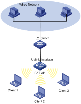
If clients want to access the wired network through the fat AP, the interface of the fat AP that connects to the wired network should be specified as the uplink interface, so that WLAN services will be provided as long as the uplink interface is up.
Following these steps to specify the uplink interface of the fat AP:
|
To do… |
Use the command… |
Remarks |
|
Enter system view |
system-view |
— |
|
Specify the uplink interface |
wlan uplink-interface interface-type interface-number |
Optional By default, no interface is configured as an uplink interface. |
Specifying a Country Code
A country code identifies the country in which you want to operate radios. It determines characteristics such as operating power level and total number of channels available for the transmission of frames. You must set the valid country code or area code before configuring an AP.
Follow these steps to specify the country code:
|
To do… |
Use the command… |
Remarks |
|
Enter system view |
system-view |
— |
|
Specify the country code |
wlan country-code code |
By default, the country code is CN. |
![]()
For information about country codes, refer to WLAN Services Command in the WLAN Volume.
Configuring Software Version Automatic Update
A fit AP is a zero-configuration device. It can automatically discover an AC after power-on. To ensure that a fit AP can associate with an AC, their software versions must be consistent by default, which complicates maintenance. This task allows you designate the software version of an AP on the AC, so that they can associate with each other even if their software versions are inconsistent.
Follow these steps to configure software version automatic update:
|
To do… |
Use the command… |
Remarks |
|
Enter system view |
system-view |
— |
|
Designate the software version of a given AP model with a given hardware version |
wlan apdb model-name hardware-version software-version |
Optional By default, the software version will be the value initialized by the driver, namely, the software versions of the fit AP and the AC should be consistent. |
Configuring a WLAN Service Template
A WLAN service template includes attributes such as SSID, WLAN-ESS interface binding, authentication method (open-system or shared key) information. A service template can be of clear or crypto type. If a clear type service template exists, you cannot change it to crypto. To do so, you must delete the clear type service template, and configure a new service template with type as crypto.
Follow these steps to configure a service template:
|
To do… |
Use the command… |
Remarks |
|
Enter system view |
system-view |
— |
|
Create a WLAN-ESS interface |
interface wlan-ess interface-index |
— Support for this command depends on the device model. This command is only supported on ACs. |
|
Exit interface view |
quit |
— |
|
Create a WLAN service template and enter WLAN service template view |
wlan service-template service-template-number { clear | crypto } |
Required No WLAN service template is created by default. |
|
Specify the service set identifier |
ssid ssid-name |
Required By default, no SSID is set. |
|
Disable the advertising of SSID in beacon frames |
beacon ssid-hide |
Optional By default the SSID is advertised in beacon frames. Note that hiding the SSID does very little to increase security. |
|
Bind the WLAN-ESS interface to the service template |
bind wlan-ess interface-index |
Required By default, no interface is bound to the service template. Support for this command depends on the device model. This command is only supported on ACs. |
|
Enable local forwarding |
client forwarding-mode local [ vlan vlan-id-list ] |
Optional Remote forwarding is enabled by default. This command is only supported on ACs. |
|
Specify an authentication method |
authentication-method { open system | shared key } |
Required For related configuration about the shared key, refer to WLAN Security in the WLAN Volume. |
|
Specify the maximum associated clients per BSS |
client max-count max-number |
Optional 64 by default. |
|
Enable the service template |
service-template enable |
Required Disabled by default. |
Configuring an AP (only supported on ACs)
Access Points are used to setup connections between the AC and stations. An AP uses radio signals to communicate with wireless clients and uses an uplink interface to connect to the wired network.
Follow these steps to configure an AP on the AC:
|
To do… |
Use the command… |
Remarks |
|
Enter system view |
system-view |
— |
|
Specify the AP name and its model number and enter AP template view |
wlan ap ap-name model model-name |
The model number needs to be specified only during new AP template creation. |
|
Configure a description for the AP |
description description-string |
Optional |
|
Configure the echo interval for the AP |
echo-interval interval |
By default, the echo interval is 10 seconds. |
|
Set the CIR for packets sent from AC to AP |
cir committed-information-rate [ cbs committed-burst-size ] |
Optional By default, no CIR is set for an AP. |
|
Configure the jumbo frame threshold |
jumboframe enable value |
By default, the jumbo frame functionality is disabled. |
|
Enable the AP to respond to broadcast probe requests |
broadcast-probe reply |
Optional By default, an AP only responds to unicast probe request frames (frames with SSID). |
|
Specify the client idle timeout interval |
client idle-timeout interval |
Optional By default, the client idle timeout is 3600 seconds. If no data is received from an associated client within the interval, the AP will remove it from the network. |
|
Specify the client keep alive interval |
client keep-alive interval |
Optional By default, the client keep-alive function is disabled. |
|
Configure the priority for the AP to connect to the AC |
priority level priority |
Optional The default is 4. |
|
Exit AP template view |
quit |
— |
|
Configure the discovery policy type as unicast |
wlan lwapp discovery-policy unicast |
Optional By default, the AC receives broadcast discovery messages. |
|
Enable/disable WLAN radios |
wlan radio { disable | enable } { radio-policy radio-policy-name | all | dot11a | dot11b | dot11g } |
Required By default, no WLAN radio is enabled. |
Configuring Auto AP
The auto AP feature allows an AP to automatically connect to an AC. When you deploy a wireless network with many APs, the auto AP function avoids configuration of many AP serial IDs, thus simplifying configuration.
Follow these steps to configure auto AP:
|
To do… |
Use the command… |
Remarks |
|
Enter system view |
system-view |
— |
|
Enable the auto-AP function |
wlan auto-ap enable |
Optional Enabled by default. |
|
Enter AP template view |
wlan ap ap-name model model-name |
The model number of the AP is specified only if an AP template is created |
|
Set auto-AP serial ID |
serial-id auto |
Required |
|
Exit AP template view |
quit |
— |
|
Convert auto AP into configured AP |
wlan auto-ap persistent { name auto-ap-name [ new-ap-name ] | all } |
Optional |
Configuring CAPWAP Dual-Link (Supported only on ACs)
Follow these steps to configure CAPWAP dual-link:
|
To do… |
Use the command… |
Remarks |
|
Enter system view |
system-view |
— |
|
Specify the address of the backup AC |
wlan backup-ac { ip ipv4-address | ipv6 ipv6-address } |
Required. By default, no backup AC address exists. |
|
Enter AP template view |
wlan ap ap-name model model-name |
The model number needs to be specified only during new AP template creation. |
|
Specify the AP connection priority for the AC |
priority level priority |
Optional By default, the AP connection priority of the AC is 4. If an AC has an AP connection priority of 7, the AC becomes the primary AC. When the primary AC fails and then recovers, it will re-establish connections with APs and become the master AP. |
![]()
You must ensure that the two ACs have the same AP configurations. Otherwise, a switchover between master and slave ACs will fail.
Configuring the Radio of an AP
Follow these steps to configure the radio of an AP (on an AC):
|
To do… |
Use the command… |
Remarks |
|
Enter system view |
system-view |
— |
|
Enter AP template view |
wlan ap ap-name model model-number |
— |
|
Specify a radio type for the radio and enter radio view |
radio radio-number [ type { dot11a | dot11b | dot11g } ] |
Required The default varies by device. WLAN supports customizing the default radio type for AP models. |
|
Map a service template to the current radio |
service-template service-template-number |
Required |
|
Specify a channel number for the radio |
channel { channel-number | auto } |
Optional. By default, auto mode is enabled. |
|
Specify the maximum radio power |
max-power max-power |
Optional. By default, the maximum radio power varies with radio types and country codes |
|
Specify the type of preamble |
preamble { long | short } |
Optional. By default, the short preamble is supported. Note that this command does not apply to 802.11a radios. |
|
Enable Adaptive Noise Immunity (ANI) function |
ani enable |
Optional. By default, ANI is enabled. |
|
Bind a radio policy to the current radio |
radio-policy radio-policy-name |
Optional. By default, the default_rp radio policy is bound to a radio. The radio policy must have been configured with the wlan radio-policy command. |
|
Enable the radio |
radio enable |
Required |
Follow these steps to configure the radio of a fat AP:
|
To do… |
Use the command… |
Remarks |
|
Enter system view |
system-view |
— |
|
Enter radio interface view |
interface wlan-radio interface-number |
— |
|
Specify a radio type for the radio |
radio-type { dot11b | dot11g | dot11a } |
Required The default radio type depends on the device model. |
|
Bind a service template to a WLAN-ESS interface for the radio |
service-template service-template-number interface wlan-bss interface-number |
Required |
|
Specify a channel number for the radio |
channel { channel-number | auto } |
Optional By default, auto mode is enabled. |
|
Specify the maximum radio power |
max-power max-power |
Optional By default, the maximum radio power varies with radio types and country codes. |
|
Specify the type of preamble |
preamble { long | short } |
Optional. By default, the short preamble is supported. Note that this command does not apply to 802.11a radios. |
Configuring a Radio Policy on an AC or the Radio of a Fat AP
Follow these steps to configure a radio policy on an AC or the radio of a fat AP:
|
To do… |
Use the command… |
Remarks |
|
|
Enter system view |
system-view |
— |
|
|
Enter radio policy view or radio view |
Create a radio policy and enter radio policy view (on an AC) |
wlan radio-policy policy-name |
— |
|
Enter radio view (on a fat AP) |
interface wlan-radio radio-number |
||
|
Set the interval for sending beacon frames |
beacon-interval interval |
Optional By default, the beacon interval is 100 time units (TUs). |
|
|
Set the number of beacon intervals between DTIM frames |
dtim counter |
Optional By default, the DTIM counter is 1. |
|
|
Specify the maximum length of packets that can be transmitted without fragmentation |
fragment-threshold size |
Optional By default, the fragment threshold is 2346 bytes. |
|
|
Specify the request to send (RTS) threshold length |
rts-threshold size |
Optional By default, the RTS threshold is 2346 bytes. |
|
|
Set the maximum number of retransmission attempts for frames larger than the RTS threshold |
long-retry threshold count |
Optional By default, the long retry threshold is 4. |
|
|
Specify the maximum number of attempts to transmit a frame shorter than the RTS threshold |
short-retry threshold count |
Optional By default, the short retry threshold is 7. |
|
|
Specify the interval for the AP to hold received packets |
max-rx-duration interval |
Optional By default, the interval is 2000 milliseconds. |
|
|
Specify the maximum number of associated clients |
client max-count max-number |
Optional The default depends on the device model. This command is only supported on ACs. |
|
Configuring 802.11n
As the next generation wireless LAN technology, 802.11n supports both 2.4GHz and 5GHz bands. It provides higher-speed services to customers by using the following two methods:
1) Increasing bandwidth: 802.11n can bond two adjacent 20-MHz channels together to form a 40-MHz channel. During data forwarding, the two 20-MHz channels can work separately with one acting as the primary channel and the other acting as the secondary channel or work together as a 40-MHz channel. This provides a simple way of doubling the data rate.
2) Improving channel utilization through the following ways:
l 802.11n introduces the A-MPDU frame format. By using only one PHY header, each A-MPDU can accommodate multiple Message Protocol Data Units (MPDUs) which have their PHY headers removed. This reduces the overhead in transmission and the number of ACK frames to be used, and thus improves network throughput.
l Similar with MPDU aggregation, multiple MAC Service Data Units (MSDU) can be aggregated into a single A-MSDU. This reduces the MAC header overhead and thus improves MAC layer forwarding efficiency.
l To improve physical layer performance, 802.11n introduces the short GI function, which shortens the GI interval of 800 us in 802.11a/g to 400 us. This can increase the data rate by 10 percent.
Follow these steps to configure 802.11n:
|
To do… |
Use the command… |
Remarks |
|
Enter system view |
system-view |
— |
|
Enter AP template view |
wlan ap ap-name model model-name |
— |
|
Enter radio view |
radio radio-number type { dot11an | dot11gn } |
— |
|
Specify the bandwidth mode for the radio |
channel band-width { 20 | 40 } |
Optional By default, the radio operates in 20 MHz mode. |
|
Enable access permission for 802.11n clients only |
client dot11n-only |
Optional By default, an 802.11a/n radio permits both 802.11a and 802.11n clients to access, and an 802.11g/n radio permits both 802.11g and 802.11n clients to access. |
|
Enable the short GI function |
short-gi enable |
Optional Enabled by default. |
|
Enable the A-MSDU function |
a-msdu enable |
Optional Enabled by default. |
|
Enable the A-MPDU function |
a-mpdu enable |
Optional Enabled by default. |
|
Enable the radio |
radio enable |
Required Disabled by default. Before enabling the radio, you must configure the Modulation and Coding Scheme (MCS). For mandatory and supported 802.11n rates, refer to WLAN RRM Configuration in the WLAN Volume. |
![]()
For information about Modulation and Coding Scheme (MCS) index and mandatory and supported 802.11n rates, refer to WLAN RRM Configuration in the WLAN Volume.
Displaying and Maintaining WLAN Service
On an AC
|
To do… |
Use the command… |
Remarks |
|
Display AP information |
display wlan ap { all | name ap-name } [ verbose ] |
Available in any view |
|
Display the model information of a specified AP or all APs supported on the AC |
display wlan ap-model { all | name ap-name } |
Available in any view |
|
Display the reboot log information of an AP |
display wlan ap reboot-log name ap-name |
Available in any view |
|
Display WLAN radio policy information |
display wlan radio-policy [ radio-policy-name ] |
Available in any view |
|
Display WLAN service template information |
display wlan service-template [ service-template-number ] |
Available in any view |
|
Display WLAN statistics |
display wlan statistics { client [ all | mac-address mac-address ] | radio [ ap-name ] } |
Available in any view. |
|
Display WLAN client information |
display wlan client { ap ap-name [ radio radio-number ] | mac-address mac-address | service-template service-template-number } [ verbose ] |
Available in any view |
|
Reset AP connection(s) |
reset wlan ap { all | name ap-name } |
Available in user view |
|
Clear WLAN AP reboot logs |
reset wlan ap reboot-log { all | name ap-name } |
Available in user view |
|
Clear WLAN statistics |
reset wlan statistics { radio [ ap-name ] | client [ all | mac-address ] } |
Available in user view |
|
Cut off WLAN client(s) |
reset wlan client { all | mac-address mac-address } |
Available in user view |
On a fat AP
|
To do… |
Use the command… |
Remarks |
|
Display WLAN client information |
display wlan client { interface wlan-radio [ wlan-radio-number ] | mac-address mac-address | service-template service-template-number } [ verbose ] |
Available in any view |
|
Display WLAN service template information |
display wlan service-template [ service-template-number ] |
Available in any view |
|
Display WLAN client statistics |
display wlan statistics client { all | mac-address mac-address } |
Available in any view |
|
Cut off client(s) |
reset wlan client { all | mac-address mac-address } |
Available in user view |
|
Clear WLAN client statistics |
reset wlan statistics client { all | mac-address mac-address } |
Available in user view |
Configuring AP Group (only supported on ACs)
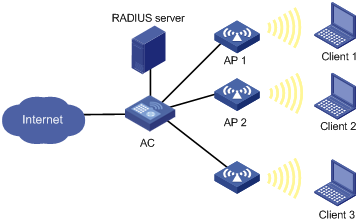
Some wireless service providers need to control the access positions of clients. For example, as shown in the figure below, to meet security or billing needs, it is required to connect wireless clients 1, 2 and 3 to the wired network through APs 1, 2 and 3 respectively. To achieve this, you can configure an AP group and then apply the AP group in a user profile.
Figure 1-16 Client access control
Configuring an AP Group
Follow these steps to configure an AP group:
|
To do… |
Use the command… |
Remarks |
|
Enter system view |
system-view |
— |
|
Create an AP group and enter AP group view |
wlan ap-group value |
— |
|
Add specified APs into the AP group |
ap template-name-list |
Required No AP is added by default. You can use this command repeatedly to add multiple APs, or add up to 10 APs in one command line. A nonexistent AP can be added. |
|
Configure a description for the AP group |
description text |
Optional Not configured by default. |
Applying the AP Group in a User Profile
Follow these steps to apply the AP group in a user profile:
|
To do… |
Use the command… |
Remarks |
|
Enter system view |
system-view |
— |
|
Enter user profile view |
user-profile profile-name |
Required If the user profile does not exist, you need to create it first. |
|
Apply the AP group in the user profile |
wlan permit-ap-group value |
Required No AP group is applied in the user profile by default. |
|
Return to system view |
quit |
— |
|
Enable the user profile |
user-profile profile-name enable |
Required Not enabled by default. Note that: The name of the user profile must be identical to that of the external group on the RADIUS server. To support roaming, all ACs in a mobility group must have the same profile name configured. |
![]()
For more information about user profile, refer to User Profile Configuration in the System Volume.
Displaying and Maintaining AP Group
|
Use the command… |
Remarks |
|
|
Display AP group information |
display wlan ap-group [ value ] |
Available in any view |
Configuring SSID-Based Access Control
When a user wants to access a WLAN temporarily, the administrator can specify a permitted SSID in the corresponding user profile so that the user can access the WLAN only through the SSID.
Specifying a Permitted SSID in a User Profile
After completing the configuration, the user profile needs to be enabled to take effect.
Follow these steps to specify a permitted SSID:
|
To do… |
Use the command… |
Remarks |
|
|
Enter system view |
system-view |
— |
|
|
Enter user profile view |
user-profile profile-name |
Required If the specified user profile does not exist, this command will create it and enter its view. |
|
|
Specify a permitted SSID |
wlan permit-ssid ssid-name |
Required No permitted SSID is specified by default, that is, users can access the WLAN without SSID limitation. |
|
|
Return to system view |
quit |
— |
|
|
Enable the user profile |
user-profile profile-name enable |
Required Not enabled by default. |
|
![]()
l For more information on user access control, refer to AAA Configuration in the Security Volume.
l For more information on user profile, refer to User Profile Configuration in the System Volume.
WLAN Service Configuration Examples
WLAN Service Configuration Example (On an AC)
Network requirements
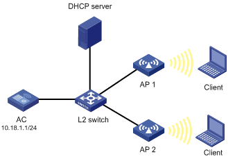
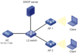
As shown in the following figure, an AC is connected to an L2 switch. AP1 (serial ID SZ001) and AP2 (serial ID SZ002) are connected to the AC through the L2 switch. AP1, AP2 and the AC are in the same network. AP1 and AP2 get their IP address from the DHCP server.
It is required to configure basic WLAN service settings on the AC.
Figure 1-17 WLAN service configuration
Configuration procedure
# Enable WLAN service, which is enabled by default.
<AC> system-view
[AC] wlan enable
# Create the WLAN ESS interface.
<AC> system-view
[AC] interface WLAN-ESS 1
[AC-WLAN-ESS1] quit
# Define a WLAN service template and bind the WLAN-ESS interface to this service template.
[AC] wlan service-template 1 clear
[AC-wlan-st-1] ssid abc
[AC-wlan-st-1] bind WLAN-ESS 1
[AC-wlan-st-1] authentication-method open-system
[AC-wlan-st-1] client max-count 10
[AC-wlan-st-1] service-template enable
[AC-wlan-st-1] quit
# Configure a radio policy (the default radio policy default-rp will be used if you don’t want to configure a new radio policy for customizing related parameters).
[AC] wlan radio-policy radpolicy1
[AC-wlan-rp-radpolicy1] beacon-interval 200
[AC-wlan-rp-radpolicy1] dtim 4
[AC-wlan-rp-radpolicy1] rts-threshold 2300
[AC-wlan-rp-radpolicy1] fragment-threshold 2200
[AC-wlan-rp-radpolicy1] short-retry threshold 6
[AC-wlan-rp-radpolicy1] long-retry threshold 5
[AC-wlan-rp-radpolicy1] max-rx-duration 500
# Configure AP1 on the AC.
<AC> system-view
[AC] wlan ap ap1 model WA2100
[AC-wlan-ap-ap1] serial-id 210235A29G007C000020
[AC-wlan-ap-ap1] description L3Office
# Configure the radio of AP1, and bind service template 1 and radio policy radiopolicy1 to the radio.
[AC-wlan-ap-ap1] radio 1 type dot11a
[AC-wlan-ap-ap1-radio-1] channel 149
[AC-wlan-ap-ap1-radio-1] max-power 10
[AC-wlan-ap-ap1-radio-1] radio-policy radiopolicy1
[AC-wlan-ap-ap1-radio-1] service-template 1
[AC-wlan-ap-ap1-radio-1] quit
[AC-wlan-ap-ap1] quit
# Configure AP2 on the AC.
[AC] wlan ap ap2 model WA2100
[AC-wlan-ap-ap2] serial-id 210235A29G007C000021
[AC-wlan-ap-ap2] description L4Office
# Configure the radio of AP2, including binding radio policy radiopolicy1 and service template 1 to the radio.
[AC-wlan-ap-ap2] radio 1 type dot11a
[AC-wlan-ap-ap2-radio-1] channel 149
[AC-wlan-ap-ap2-radio-1] max-power 10
[AC-wlan-ap-ap2-radio-1] radio-policy radiopolicy1
[AC-wlan-ap-ap2-radio-1] service-template 1
[AC-wlan-ap-ap2-radio-1] quit
[AC-wlan-ap-ap2] quit
# Enable all radios.
[AC] wlan radio enable all
WLAN Auto-AP Configuration Example (On an AC)
Network requirements
As shown in the following figure, an AC is connected to a Layer 2 switch. AP1 (serial ID SZ001) and AP2 (serial ID SZ002) are connected to the AC through the L2 switch. AP1, AP2 and the AC are in the same network. AP1 and AP2 get their IP address from the DHCP server. It is required to enable the auto-AP function to enable APs to automatically connect to the AC.
Figure 1-18 WLAN service configuration
Configuration procedure
# Create a WLAN ESS interface.
<AC> system-view
[AC] interface WLAN-ESS 1
[AC-WLAN-ESS1] quit
# Define a WLAN service template and bind the WLAN-ESS interface to this service template.
[AC] wlan service-template 1 clear
[AC-wlan-st-1] ssid abc
[AC-wlan-st-1] bind WLAN-ESS 1
[AC-wlan-st-1] authentication-method open-system
[AC-wlan-st-1] service-template enable
[AC-wlan-st-1] quit
# Configure a radio policy (the default radio policy default_rp will be used if you don’t want to configure a new radio policy for customizing related parameters).
[AC] wlan radio-policy radpolicy1
[AC-wlan-rp-radpolicy1] beacon-interval 200
[AC-wlan-rp-radpolicy1] dtim 4
[AC-wlan-rp-radpolicy1] rts-threshold 2300
[AC-wlan-rp-radpolicy1] fragment-threshold 2200
[AC-wlan-rp-radpolicy1] short-retry threshold 6
[AC-wlan-rp-radpolicy1] long-retry threshold 5
[AC-wlan-rp-radpolicy1] max-rx-duration 500
[AC-wlan-rp-radpolicy1] quit
# Configure the AP auto configuration feature.
[AC] wlan auto-ap enable
# Configure a common AP for model WA2100 (For each AP model, one common auto AP configuration is required).
[AC] wlan ap ap1 model WA2100
[AC-wlan-ap-ap1] serial-id auto
# Configure the radio of the common AP.
[AC-wlan-ap-ap1] radio 1 type dot11a
[AC-wlan-ap-ap1-radio-1] max-power 10
[AC-wlan-ap-ap1-radio-1] radio-policy radiopolicy1
[AC-wlan-ap-ap1-radio-1] service-template 1
[AC-wlan-ap-ap1-radio-1] radio enable
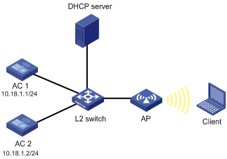
CAPWAP Dual-Link Configuration Example (On an AC)
Network requirements
As shown in the following figure, AC1 and AC2 are connected to a L2 switch. An AP is connected to AC1 and AC2 through the L2 switch. AC1, AC2 and the AP are in the same network. The AP gets its IP address from the DHCP server. The IP address of AC1 is 10.18.1.1 and the IP address of AC2 is 10.18.1.2. AC1 is working in master mode while AC2 is working in slave mode. When AC2 detects AC1 is down, AC2 will convert its work mode from slave to master. The AP which is connected to AC2 through a slave tunnel will transform the tunnel mode to master and use AC2 as the master AC.
Figure 1-19 CAPWAP dual link configuration
Configuration procedure
1) Configuration on AC1.
# Define the WLAN ESS interface.
<AC1> system-view
[AC1] interface WLAN-ESS 1
[AC1-WLAN-ESS1] quit
# Define a WLAN service template and bind the WLAN-ESS interface to this service template.
[AC1] wlan service-template 1 clear
[AC1-wlan-st-1] ssid abc
[AC1-wlan-st-1] bind WLAN-ESS 1
[AC1-wlan-st-1] authentication-method open-system
[AC1-wlan-st-1] service-template enable
[AC1-wlan-st-1] quit
# Specify the backup AC address.
[AC1] wlan backup-ac ip 10.18.1.2
# Configure the AP on AC1.
[AC1] wlan ap ap1 model WA2100
[AC1-wlan-ap-ap1] serial-id 210235A29G007C000020
# Configure the radio of the AP.
[AC1-wlan-ap-ap1] radio 1 type dot11g
[AC1-wlan-ap-ap1-radio-1] service-template 1
[AC1-wlan-ap-ap1-radio-1] radio enable
2) Configuration on AC2.
# Define the WLAN ESS interface.
<AC2> system-view
[AC2] interface wlan-ess 1
[AC2-WLAN-ESS1] quit
# Define a WLAN service template and bind the WLAN-ESS interface to this service template.
[AC2] wlan service-template 1 clear
[AC2-wlan-st-1] ssid abc
[AC2-wlan-st-1] bind WLAN-ESS 1
[AC2-wlan-st-1] authentication-method open-system
[AC2-wlan-st-1] service-template enable
[AC2-wlan-st-1] quit
# Specify the backup AC address.
[AC2] wlan backup-ac ip 10.18.1.1
# Configure the AP on AC2.
[AC2] wlan ap ap1 model WA2100
[AC2-wlan-ap-ap1] serial-id 210235A29G007C000021
# Configure the radio of the AP.
[AC2-wlan-ap-ap1] radio 1 type dot11g
[AC2-wlan-ap-ap1-radio-1] service-template 1
[AC2-wlan-ap-ap1-radio-1] radio enable
802.11n Configuration Example
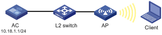
Network requirements
As shown below, an AP is connected to an AC with IP address 10.18.1.1/24 through a Layer 2 switch. Configure the AP to support 802.11n.
Figure 1-20 802.11n configuration
Configuration procedure
# Configure a WLAN-ESS interface.
<AC> system-view
[AC] interface wlan-ess 1
[AC-WLAN-ESS1] quit
# Configure a service template and bind the WLAN-ESS interface with the service template.
[AC] wlan service-template 1 clear
[AC-wlan-st-1] ssid abc
[AC-wlan-st-1] bind WLAN-ESS 1
[AC-wlan-st-1] authentication-method open-system
[AC-wlan-st-1] service-template enable
[AC-wlan-st-1] quit
# Configure the AP on the AC.
[AC] wlan ap ap1 model WA2610E-AGN
[AC-wlan-ap-ap1] serial-id 210235A29G007C000020
# Configure the radio of the AP to operate in 802.11g/n mode.
[AC-wlan-ap-ap1] radio 1 type dot11gn
# Configure the working bandwidth of the radio as 40MHz.
[AC-wlan-ap-ap1-radio-1] channel band-width 40
[AC-wlan-ap-ap1-radio-1] service-template 1
[AC-wlan-ap-ap1-radio-1] radio enable
WLAN Service Configuration Example (on a FAT AP)
Network requirements
l As shown below, a fat AP is connected to a Layer 2 switch. The IP address of the fat AP is 10.18.1.10.
l It is required to configure WLAN service on the FAT AP.
Figure 1-21 Network diagram for WLAN service configuration

Configuration procedure
# Define the WLAN BSS interface.
<Sysname> system-view
[Sysname] interface wlan-bss 1
[Sysname-WLAN-BSS1] quit
# Define a WLAN service template and enable it.
[Sysname] wlan service-template 1 clear
[Sysname-wlan-st-1] ssid abc
[Sysname-wlan-st-1] authentication-method open-system
[Sysname-wlan-st-1] service-template enable
[Sysname-wlan-st-1] quit
# Configure the radio of the fat AP.
[Sysname] interface wlan-radio 1/0/1
[Sysname-WLAN-Radio1/0/1] radio-type dot11a
[Sysname-WLAN-Radio1/0/1] channel 149
[Sysname-WLAN-Radio1/0/1] service-template 1 interface wlan-bss 1
# Configure global WLAN parameters.
<Sysname> system-view
[Sysname] wlan client idle-timeout 3600
[Sysname] wlan client keep-alive 100
[Sysname] wlan broadcast-probe reply
AP Group Configuration Examples
AP Group Configuration without Roaming
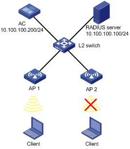
Network requirements
As shown in the figure below, configure an AP group and apply it in a user profile on the AC, so that a client can only access the WLAN through AP 1.
Figure 1-22 Client access control configuration diagram
Configuration procedure
1) Configuration on the AC
# Enable port security.
<AC> system-view
[AC] port-security enable
# Enable EAP authentication mode.
[AC] dot1x authentication-method eap
# Create a RADIUS scheme.
[AC] radius scheme wlan-user-policy
# Specify the RADIUS server and keys for authentication and accounting.
[AC-radius-wlan-user-policy] server-type extended
[AC-radius-wlan-user-policy] primary authentication 10.100.100.100
[AC-radius-wlan-user-policy] primary accounting 10.100.100.100
[AC-radius-wlan-user-policy] key authentication wlan
[AC-radius-wlan-user-policy] key accounting wlan
# Specify the IP address of the AC.
[AC-radius-wlan-user-policy] nas-ip 10.100.100.200
[AC-radius-wlan-user-policy] quit
# Configure an ISP domain named universal by referencing the configured RADIUS scheme.
[AC] domain universal
[AC-isp-universal] authentication default radius-scheme wlan-user-policy
[AC-isp-universal] authorization default radius-scheme wlan-user-policy
[AC-isp-universal] accounting default radius-scheme wlan-user-policy
[AC-isp-universal] quit
# Configure domain universal as the default domain.
[AC] domain default enable universal
# Configure port security on interface WLAN-ESS 1.
[AC] interface wlan-ess 1
[AC-WLAN-ESS1] port-security port-mode userlogin-secure-ext
[AC-WLAN-ESS1] port-security tx-key-type 11key
[AC-WLAN-ESS1] undo dot1x multicast-trigger
[AC-WLAN-ESS1] undo dot1x handshake
[AC-WLAN-ESS1] quit
# Configure a service template.
[AC] wlan service-template 1 crypto
[AC-wlan-st-1] ssid test
[AC-wlan-st-1] bind wlan-ess 1
[AC-wlan-st-1] authentication-method open-system
[AC-wlan-st-1] cipher-suite ccmp
[AC-wlan-st-1] security-ie rsn
[AC-wlan-st-1] service-template enable
[AC-wlan-st-1] quit
# Configure AP1.
[AC] wlan ap ap1 model wa2100
[AC-wlan-ap-ap1] radio 1 type dot11g
[AC-wlan-ap-ap1-radio1] service-template 1
[AC-wlan-ap-ap1-radio1] radio enable
[AC-wlan-ap-ap1-radio1] return
# Add AP1 to AP group 11, apply the AP group to user profile management and enable the user profile.
<AC> system-view
[AC] wlan ap-group 11
[AC-ap-group11] ap ap1
[AC-ap-group11] quit
[AC] user-profile management
[AC-user-profile-management] wlan permit-ap-group 11
[AC-user-profile-management] quit
[AC] user-profile management enable
2) Configuration on the RADIUS server
# Specify the name of the user profile in the external group checkbox on the RADIUS server.
Log in to the CAMS management platform. On the left navigation tree, select Service Management > Service Config. Then click Add on the page to enter the following configuration page.
Select the Access Control checkbox and add name management.
![]()
If no user profile name is specified, all APs are permitted.
Figure 1-23 Specify a user profile name
![]()
3) Verify the configuration
The AP group applied in the user profile contains only AP 1, and thus a client can only access the WLAN through AP 1.
AP Group Configuration for Inter-AC Roaming
Network requirements
As shown in the figure below, AC1 and AC2 belong to the same mobility group. Configure an AP group on the ACs so that a client can still access the WLAN when it moves from between APs.
Figure 1-24 AP group configuration for inter-AC roaming
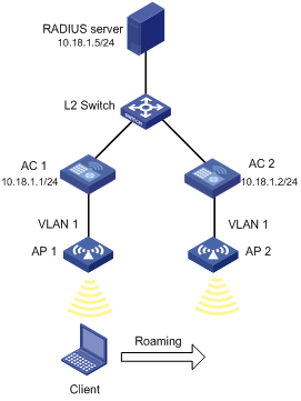
Configuration procedure
![]()
Configuration on the RADIUS server is similar with that in AP Group Configuration without Roaming and thus is omitted.
1) Configuration on AC 1
# Configure AP 1.
<AC1> system-view
[AC1] port-security enable
[AC1] dot1x authentication-method eap
[AC1] interface wlan-ess 1
[AC1-WLAN-ESS1] port-security port-mode userlogin-secure-ext
[AC1-WLAN-ESS1] port-security tx-key-type 11key
[AC1-WLAN-ESS1] undo dot1x multicast-trigger
[AC1-WLAN-ESS1] undo dot1x handshake
[AC1-WLAN-ESS1] quit
[AC1] wlan service-template 1 crypto
[AC1-wlan-st-1] ssid abc
[AC1-wlan-st-1] bind wlan-ess 1
[AC1-wlan-st-1] authentication-method open-system
[AC1-wlan-st-1] cipher-suite ccmp
[AC1-wlan-st-1] security-ie rsn
[AC1-wlan-st-1] service-template enable
[AC1-wlan-st-1] quit
[AC1] wlan ap ap1 model WA2100
[AC1-wlan-ap-ap1] serial-id 210235A045B05B1236548
[AC1-wlan-ap-ap1] radio 1 type dot11g
[AC1-wlan-ap-ap1-radio-1] service-template 1
[AC1-wlan-ap-ap1-radio-1] radio enable
[AC1-wlan-ap-ap1-radio-1] quit
[AC1-wlan-ap-ap1] quit
# Configure mobility group abc and enable the mobility group.
[AC1] wlan mobility-group abc
[AC1-wlan-mg-abc] source ip 10.18.1.1
[AC1-wlan-mg-abc] member ip 10.18.1.2
[AC1-wlan-mg-abc] mobility-group enable
[AC1-wlan-mg-abc] return
# Configure AP group 1, add AP 1 and AP 2 in it, apply it in user profile management, and enable the user profile.
<AC1> system-view
[AC1] wlan ap-group 1
[AC1-ap-group1] ap ap1 ap2
[AC1-ap-group1] quit
[AC1] user-profile management
[AC1-user-profile-management] wlan permit-ap-group 1
[AC1-user-profile-management] quit
[AC1] user-profile management enable
2) Configuration on AC 2
# Configure AP 2.
<AC2> system-view
[AC2] port-security enable
[AC2] dot1x authentication-method eap
[AC2] interface wlan-ess 1
[AC2-WLAN-ESS1] port-security port-mode userlogin-secure-ext
[AC2-WLAN-ESS1] port-security tx-key-type 11key
[AC2-WLAN-ESS1] undo dot1x multicast-trigger
[AC2-WLAN-ESS1] undo dot1x handshake
[AC2-WLAN-ESS1] quit
[AC2] wlan service-template 1 crypto
[AC2-wlan-st-1] ssid abc
[AC2-wlan-st-1] bind wlan-ess 1
[AC2-wlan-st-1] authentication-method open-system
[AC2-wlan-st-1] cipher-suite ccmp
[AC2-wlan-st-1] security-ie rsn
[AC2-wlan-st-1] service-template enable
[AC2-wlan-st-1] quit
[AC2] wlan ap ap1 model WA2100
[AC2-wlan-ap-ap1] serial-id 210235A22W0076000103
[AC2-wlan-ap-ap1] radio 1 type dot11g
[AC2-wlan-ap-ap1-radio-1] service-template 1
[AC2-wlan-ap-ap1-radio-1] radio enable
[AC2-wlan-ap-ap1-radio-1] quit
[AC2-wlan-ap-ap1] quit
# Configure mobility group abc and enable the mobility group.
[AC2] wlan mobility-group abc
[AC2-wlan-mg-abc] source ip 10.18.1.2
[AC2-wlan-mg-abc] member ip 10.18.1.1
[AC2-wlan-mg-abc] mobility-group enable
[AC2-wlan-mg-abc] quit
# Configure AP group 1, add AP 1 and AP 2 in it, apply it in user profile management, and enable the user profile.
[AC2] wlan ap-group 1
[AC2-ap-group1] ap ap1 ap2
[AC2-ap-group1] quit
[AC2] user-profile management
[AC2-user-profile-management] wlan permit-ap-group 1
[AC2-user-profile-management] quit
[AC2] user-profile management enable
3) Verify the configuration
Since AP 1 and AP 2 are permitted in the AP group, a client can roam between them.
