- Table of Contents
- Related Documents
-
| Title | Size | Download |
|---|---|---|
| 05-Layer 2 Software Forwarding Configuration | 95.85 KB |
Table of Contents
1 Layer 2 Software Forwarding Configuration
Layer 2 Software Forwarding Overview
Configuring Layer 2 Software Forwarding
Displaying and Maintaining Layer 2 Software Forwarding
Layer 2 Software Forwarding Configuration Example
The support for this feature depends on the specific model of the MSR series routers.
![]()
l Refer to the command manual of this module for command and parameter support, default values and value ranges of the MSR series routers.
l All the models of the MSR series routers are centralized devices.
When configuring Layer 2 software forwarding, go to these sections for information you are interested in:
l Layer 2 Software Forwarding Overview
l Configuring Layer 2 Software Forwarding
l Displaying and Maintaining Layer 2 Software Forwarding
l Layer 2 Software Forwarding Configuration Example
Layer 2 Software Forwarding Overview
General Layer 2 forwarding is implemented by hardware; while Layer 2 software forwarding is implemented by software. When stations, or stations and PCs are in the same VLAN, packet forwarding is implemented through Layer 2 software forwarding; while when they are not in the same VLAN, packet forwarding is implemented through Layer 3 forwarding.
Layer 2 software forwarding supports QoS and port security, and therefore can provide control on service quality and secure access. It also supports broadcast storm suppression.
Configuring Layer 2 Software Forwarding
Follow these steps to configure Layer 2 software forwarding:
|
To do… |
Use the command… |
|
Enter system view |
system-view |
|
Enable Layer 2 software forwarding |
l2fw fast-forwarding |
Displaying and Maintaining Layer 2 Software Forwarding
|
To do… |
Use the command… |
Remarks |
|
Display Layer 2 software forwarding statistics |
display l2fw statistics |
Available in any view |
|
Reset Layer 2 software forwarding statistics |
reset l2fw statistics |
Available in user view |
|
Display the Layer 2 fast forwarding cache entries |
display l2-fast-forward cache |
Available in any view |
|
Reset the Layer 2 fast forwarding cache entries |
reset l2-fast-forward cache |
Available in user view |
Layer 2 Software Forwarding Configuration Example
Network requirements
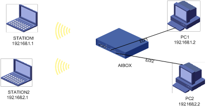
Two stations (STATION1 and STATION2) and two PCs (PC1 and PC2) are interconnected through a device.
l STATION1 is connected to the device through WLAN-BSS1, and STATION2 is connected to the device through WLAN-BSS2; PC1 is connected to the device through Ethernet 0/1, and PC2 is connected to the device through Ethernet 0/2.
l STATION1 and PC1 belong to VLAN 2, and STATION2 and PC2 belong to VLAN 3.
l The Basic Service Set Identifier (BSSID) of STATION1 is SSID1, shared key authentication and Wired Equivalent Privacy (WEP) are adopted to ensure security; the BSSID of STATION2 is SSID2, Wi-Fi Protected Access-Phase Shift Keying (WPA-PSK) authentication and Temporal Key Integrity Protocol (TKIP) encryption are adopted to ensure security.
Network diagram
Figure 1-1 Network diagram for Layer 2 software forwarding configuration
Configuration procedure
# Enter the view of interface WLAN-BSS1 and create VLAN 2. Add interface WLAN-BSS1 to VLAN 2.
<H3C> system-view
[H3C] interface WLAN-BSS 1
[H3C-WLAN-BSS1] vlan 2
[H3C-vlan2] port wlan-bss 1
# Add Ethernet 0/1 to VLAN 2.
[H3C-vlan2] port Ethernet 0/1
# Enter the view of interface WLAN-BSS2 and create VLAN 3. Add interface WLAN-BSS2 to VLAN 3.
[H3C-vlan2] interface wlan-bss 2
[H3C-WLAN-BSS2] vlan 3
[H3C-vlan3] port wlan-bss 2
# Add Ethernet 0/2 to VLAN 3.
[H3C-vlan3] port ethernet 0/2
# Enable the port security function.
[H3C-vlan3] quit
[H3C] port-security enable
Please wait......... Done.
# Create WLAN service-template 1 and enter its view.
[H3C] wlan service-template 1 crypto
# Configure SSID.
[H3C-wlan-st-1] ssid ssid1
# Configure the authentication method, encryption algorithm and key.
[H3C-wlan-st-1] authentication-method shared-key
[H3C-wlan-st-1] cipher-suite wep40
[H3C-wlan-st-1] wep default-key 1 wep40 pass-phrase 12345
# Enter WLAN-Radio interface view and associate WLAN service-template 1 with interface WLAN-BSS1.
[H3C-wlan-st-1] int wlan-radio 2/0
[H3C-WLAN-Radio2/0] service-template 1 wlan-bss 1
# Enter the view of WLAN service-template 1 and enable service.
[H3C-WLAN-Radio2/0] wlan service-template 1
[H3C-wlan-st-1] service enable
# Create WLAN service-template 2 and enter its view.
[H3C-wlan-st-1] quit
[H3C] wlan service-template 2 crypto
# Configure SSID.
[H3C-wlan-st-2] ssid ssid2
# Configure the authentication method, encryption algorithm and key.
[H3C-wlan-st-2] authentication-method open-system
[H3C-wlan-st-2] cipher-suite tkip
[H3C-wlan-st-2] security-ie wpa
# Configure the port security function on interface WLAN-BSS2.
[H3C-wlan-st-2] interface wlan-bss 2
[H3C-WLAN-BSS2] port-security port-mode psk
[H3C-WLAN-BSS2] port-security tx-key-type 11key
[H3C-WLAN-BSS2] port-security preshared-key pass-phrase 12345678
# Enter WLAN-Radio interface view and associate WLAN service-template 2 with interface WLAN-BSS2.
[H3C-wlan-st-2] int wlan-radio 2/0
[H3C-WLAN-Radio2/0] service-template 2 wlan-bss 2
# Enter the view of WLAN service-template 2 and enable service.
[H3C-WLAN-Radio2/0] wlan service-template 2
[H3C-wlan-st-2] service enable
Verify the configuration
# PC1 can be pinged successfully on STATION1.
C:\Documents and Settings\STATION1>ping 192.168.1.2
Pinging 192.168.0.2 with 32 bytes of data:
Reply from 192.168.1.2: bytes=32 time=55ms TTL=128
Reply from 192.168.1.2: bytes=32 time=2ms TTL=128
Reply from 192.168.1.2: bytes=32 time=2ms TTL=128
Reply from 192.168.1.2: bytes=32 time=2ms TTL=128
# PC2 can be pinged successfully on STATION2.
C:\Documents and Settings\STATION2>ping 192.168.2.2
Pinging 192.168.0.3 with 32 bytes of data:
Reply from 192.168.2.2: bytes=32 time=55ms TTL=128
Reply from 192.168.2.2: bytes=32 time=2ms TTL=128
Reply from 192.168.2.2: bytes=32 time=2ms TTL=128
Reply from 192.168.2.2: bytes=32 time=2ms TTL=128
# PC1 cannot be pinged successfully on STATION2.
C:\Documents and Settings\STATION2>ping 192.168.1.1
Pinging 192.168.1.1 with 32 bytes of data:
Request timed out.
Request timed out.
Request timed out.
Request timed out.
Ping statistics for 192.168.1.1:
Packets: Sent = 4, Received = 0, Lost = 4 (100% loss)
