- Table of Contents
- Related Documents
-
| Title | Size | Download |
|---|---|---|
| 06-MPLS Hybrid Insertion Configuration | 138.98 KB |
Chapter 1 MPLS Hybrid Insertion Configuration
1.1.1 Introduction to MPLS Hybrid Insertion
1.1.2 MPLS Hybrid Insertion Mechanism
1.2 Restrictions on MPLS Hybrid Insertion Networking
1.2.1 Rules of MPLS Hybrid Insertion Configuration
1.2.2 Restrictions in MPLS Hybrid Insertion
1.3 MPLS Hybrid Insertion Configuration Task
1.3.1 Introduction to MPLS hybrid insertion configuration task
1.3.2 Configuring Routing Protocols
1.3.3 Configuring Basic Capability of MPLS
1.3.5 Configuring Flow Template and ACL Rules
1.3.6 Applying Flow Template and Redirection in Port Mode
1.3.7 Typical Networking Example
1.4 Restrictions in Networking of Various MPLS Cards
1.4.1 Exclusively Non-MPLS Cards
1.4.3 Exclusively VPLS Service Cards
1.4.4 Combination of One MPLS Card and Multiple Non-MPLS Cards
1.4.5 Combination of Multiple MPLS cards and Multiple Non-MPLS Cards
1.4.6 Combination of One VPLS Card and Multiple Non-MPLS Cards
1.4.7 Combination of One VPLS card and Multiple MPLS Cards
1.4.8 Combination of One VPLS card, One MPLS Card and Multiple Non-MPLS Cards
Chapter 1 MPLS Hybrid Insertion Configuration
When performing MPLS hybrid insertion, go to these sections for information you are interested in:
l Overview
l Restrictions on MPLS Hybrid Insertion Networking
l MPLS Hybrid Insertion Configuration Task
l Restrictions in Networking of Various MPLS Cards
1.1 Overview
1.1.1 Introduction to MPLS Hybrid Insertion
For S9500 series routing switches, only the interface cards with suffixes C, CA and CB and VPLS service processor cards support MPLS function. If you want to enable MPLS VPN function of S9500 switches, you need MPLS-supporting interface cards or VPLS service processor cards. The MPLS hybrid insertion feature is used to enable deployment of MPLS VPN services on cards that do not support MPLS. S9500 routing switches support various modes of MPLS VPN function and provide abundant and differentiated MPLS VPN service to meet the differentiated needs of different users in the performance, reliability, port utilization of MPLS VPN functions.
& Note:
l Unless otherwise specified, MPLS VPN services are processed by the MPLS-supporting interface cards. In this manual, an interface card that supports MPLS function is called MPLS card for short, and an interface card that does not support MPLS function is called non-MPLS card for short.
l The purpose of MPLS hybrid insertion is to enable the non-MPLS cards to support MPLS function through the MPLS cards. Refer to the VPN section in this manual for the information on the processing of MPLS VPN through VPLS service processor cards.
1.1.2 MPLS Hybrid Insertion Mechanism
The implementation mechanism for MPLS hybrid insertion is as follows.
l The MPLS card and the non-MPLS card co-exist in the same switch;
l Use the port of the non-MPLS card for the access to the service private network side of the MPLS VPN ;
l Redirect the port of the non-MPLS card through QACL, to redirect the received packets to the specified MPLS card for processing;
l The port of MPLS card is set as Loopback port automatically and the port type is Trunk;
l The access port of the non-MPLS card and the Loopback port of the MPLS card belong to the same VLAN.
The port on the MPLS card can also be used for the access to the service private network side of the MPLS VPN. In this case, you do not need to configure MPLS hybrid insertion, and you must use the port of the MPLS card for the connection with the MPLS public network side.
& Note:
Because the destination port in MPLS hybrid insertion configuration is to be looped back and therefore is locked automatically, you cannot enter the port view. Therefore, you cannot perform other configurations on the destination port.
1.2 Restrictions on MPLS Hybrid Insertion Networking
1.2.1 Rules of MPLS Hybrid Insertion Configuration
l A non-MPLS card can be used for access to the private network side, and an MPLS card must be used for access to the public network side;
l You cannot perform other configurations on the destination port in MPLS hybrid insertion networking, that is to say, the port view is unavailable. In addition, the destination port in MPLS hybrid insertion networking cannot be deleted from the VLAN in the normal way, and the destination port is an inloop port;
l The configured connection status of the source port in MPLS hybrid insertion networking is protected. For example, the port type cannot be changed form Trunk to Access or from Access to Trunk, and the source port cannot be deleted from VLAN in the normal way;
l The configuration of the service ports in MPLS hybrid insertion networking cannot be changed, and the service ports can be reconfigured only after the MPLS hybrid insertion configuration is removed;
l In a VLAN, multiple ports of the non-MPLS card can be redirected to one port of the MPLS card. The destination port of the MPLS card is Looped back automatically (becomes a Loopback port) after it is configured for redirection, and you cannot perform other configurations on the port. Therefore, make sure that the destination port is not in manual Shutdown state before configuring redirection. Only one Loopback port is allowed in the redirected VLAN that the destination port belongs to, but other MPLS card ports are allowed to join in;
l On the Trunk port of a non-MPLS card, you can redirect the MPLS VPNs of multiple VLANs to one destination port to meet the need when the access CE is a Layer 2 switch;
l In non-MPLS hybrid insertion networking, VLL application requires that VLANs with only one port be used at the private network side; In MPLS hybrid insertion networking, VLL supports only VLANs with two ports: one is the source port (port of the non-MPLS card) and the other is the destination port (port of the MPLS card);
l When the source port (Trunk port) in MPLS hybrid insertion networking belongs to multiple VLANs, VPN binding must be implemented on the VLAN interfaces after the redirection configuration;
l If VRRP is configured on the VLAN interface to which the redirected source port of the MPLS VPN belongs, the plugging/unplugging of the MPLS card will cause VRRP group state switching on the VLAN interface.
1.2.2 Restrictions in MPLS Hybrid Insertion
l Source port aggregation and destination port aggregation are not supported;
l Nested VPN is not supported;
l Super VLAN is not supported;
l It is not allowed to change the attributes of the redirected source port;
l It is not allowed to make the redirected source port or destination port to leave redirected VLAN in the normal way;
l It is not allowed to configure protocol VLANs on the redirected source port or destination port;
l It is not allowed to delete the redirected VLAN or VLAN interface;
l It is not allowed to configure/add Loopback ports in the redirected VLAN;
l It is not allowed to use STP edge port as the redirected destination port;
l It is not allowed to change the VLANs and the default VLAN ID which the redirected destination port is permitted to pass;
l If normal ports are used, 4,094 VLL VPNs are supported; if the Trunk port of the card of a fast Ethernet card is used, a maximum of 1024 VLL VPNs are supported;
l Only cards with suffix CA can be used at the public network/private network side for VLL configuration;
l Redirection configuration for MPLS VPN hybrid insertion is not supported on the POS and RPR ports, and the POS port cannot be used as the destination port for MPLS VPN redirection;
A Trunk-type 100M Ethernet port can use only 1024 VLANs for VPN access or MPLS forwarding, but you can specify the start VLAN ID of the 100M Ethernet Trunk port. Assume the start VLAN ID is VLAN ID, the range of VLAN IDs of the VLANs that pass a certain 100M Ethernet port is from VLAN ID to VLAN ID + 1023.
1.3 MPLS Hybrid Insertion Configuration Task
1.3.1 Introduction to MPLS hybrid insertion configuration task
Table 1-1 Introduction to MPLS hybrid insertion configuration task
|
Operation |
Description |
Related section |
|
Configure public network routing protocols |
Required |
|
|
Configure the basic capability of MPLS |
Required |
Refer to MPLS Configuration of this manual. |
|
Configure MPLS VPN |
Required |
Refer to MPLS L3VPN Configuration of this manual. |
|
Configure flow template and ACL rules |
Required |
|
|
Apply flow template on the port and configure redirection |
Required |
1.3.2 Configuring Routing Protocols
The Switch should be configured with some basic routing configurations so that it can exchange public network routing information with other P devices and PE devices. The routing protocols available currently include: static routing, RIP, OSPF, BGP and so on. Refer to the corresponding parts of the IP Routing Volume.
1.3.3 Configuring Basic Capability of MPLS
Configure MPLS basic capability to enable MPLS and LDP globally and on the public network interface, to establish an LSP tunnel for the public network. Refer to MPLS Configuration of this volume for related information.
1.3.4 Configuring MPLS VPN
Configure BGP/MPLS VPN (L3VPN) or L2VPN. Refer to MPLS L3VPN Configuration of this volume for related information.
1.3.5 Configuring Flow Template and ACL Rules
The packets to be redirected are identified through the flow template and ACL configurations.
I. For L2VPN
Follow these steps to configure the flow template and ACL of L2VPN:
|
To do… |
Use the command… |
Remarks |
|
Enter system view |
system-view |
— |
|
Enter corresponding ACL view |
acl { number acl-number | name acl-name link ] } [ match-order { config | auto } ] |
Required |
|
Configure rules of ACL |
rule [ rule-id ] permit ingress vlan-id |
Required L2VPN can use either the default flow template or a custom flow template. It is recommended to redirect the packets in the specified VLAN through matching them with a Layer 2 rule so that the specified VLAN packets can pass. |
II. For L3VPN
Follow these steps to configure flow template and ACL rules of L3VPN:
|
To do… |
Use the command… |
Remarks |
|
Enter system view |
system-view |
— |
|
Set self-defined flow template |
flow-template user-defined slot slotid dmac wildcard sip wildcard vlanid |
Required When a custom flow template is specified, at least two items IP and DMAC are required. You can use the IP + VLAN + DMAC method to define the flow template so that different kinds of packets are processed in different ways. |
|
Enter corresponding ACL view |
acl { number acl-number | name acl-name [ advanced | basic ] } [ match-order { config | auto } ] |
Required |
|
Configure IP ACL |
rule [ rule-id ] permit source { source-addr wildcard | any } |
Required You can use the parameter permit any or specify an IP address. |
|
Configure Layer 2 ACL |
rule [ rule-id ] permit ingress vlan-id egress dest-mac-addr dest-mac-wildcard |
Required Use a Layer 2 rule to configure VLAN + DMAC. DMAC refers to the virtual MAC of the switch. You can get it through the display interface vlan vlanid command. |
You can define the flow template by means of the IP + VLAN + DMAC method to make sure that different kinds of packets are processed in different ways:
l If ARP packets do not match IP rules in redirection, they will be processed on the non-MPLS card;
l If Layer 2 traffic does not match DMAC in redirection, it will be L2-forwarded on the non-MPLS card;
l If Layer 3 packets (including unicast protocol packets) match the rule, they will be redirected to the MPLS card.
Refer to ACL Configuration of the QoS ACL volume for information about configuring flow template and ACL rules.
1.3.6 Applying Flow Template and Redirection in Port Mode
Follow these steps to apply flow template and redirect in port mode:
|
To do… |
Use the command… |
Remarks |
|
Enter system view |
system-view |
— |
|
Enter port view |
interface interface-type interface-number |
— |
|
Apply flow template in port mode |
flow-template user-defined |
Required |
|
Configure the traffic-redirect command |
traffic-redirect inbound ip-group { acl-number | acl-name } [ rule rule] link-group [ rule rule ] interface interface-type interface-number destination-vlan { l2-vpn | l3-vpn } slot slotid vlanid [Join-vlan ] } |
Required l3-vpn | l2-vpn means the command is applicable to L2VPN or L3VPN of MPLS. slot slotid vlanid: the slot id of the service card which the VPLS packets are redirected to and the ID of the VLAN to join in. |
The traffic-redirect command is used to enable ACL flow classification and redirect the packets (only applicable to the rules whose action is permit in the ACL). There are two kinds of redirection commands:
l Redirect packets to a port: You can redirect packets received by the source port of the non-MPLS card to the specified destination port of the MPLS card.
l Redirect packets to a service processor card: You can redirect packets received by the source port of the non-MPLS card or MPLS card to the VPLS card.
There are two kinds of redirection services:
l VPLS-related redirection services: The key word join-vlan must be specified, and the system will add the current port into destination-vlan after the redirection enabled; when redirection is disabled, the system will log the current port out of the VLAN if what is deleted is a join-vlan enabled redirection in the VLAN.
l MPLS-independent redirection services: Such redirection services include NAT, URPT, reflexive ACL, BT traffic control and so on. join-vlan cannot be enabled in such a service. The port will not be added into VLAN when redirection is configured, and the port will not be removed from the VLAN when redirection is deleted.
& Note:
l The source port joins in the corresponding VLAN automatically after the configuration of MPLS hybrid insertion redirection, and the source port leaves the corresponding VLAN automatically after the MPLS hybrid insertion redirection is deleted.
l When using the VPLS hybrid insertion redirection command, you have to enable join-vlan explicitly.
l When using the VLL VPN hybrid insertion redirection command, you must not enable the QinQ function on the source port and destination port.
1.3.7 Typical Networking Example
I. Network requirements
l CE1 and CE3 constitute VPN A, and CE2 and CE4 constitute VPN B. In PE1, a port of an interface card with suffix CA is shared, and in PE2, a Layer 2 switch is shared to connect with the host directly.
l The PE devices (PE1 and PE2) are S9500 series switches, and the PE devices need to support the MPLS function. CE1 and CE2 are common mid-range and low-end routers. CE3 and CE4 are Layer 2 switches connected with users directly.
l The configurations of the interface cards of the two PE devices are the same. On slot3 is a non-MPLS card with 100M Ethernet ports, and on Slot 2 is an MPLS card with Gigabit Ethernet ports.
II. Networking diagram
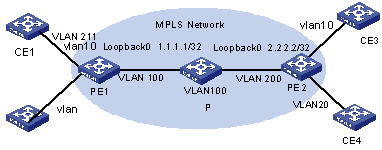
Figure 1-1 Network diagram for BGP/MPLS VPN hybrid insertion
III. Configuration procedure
1) Configure CE1
# Configure CE1 and CE2 as EBGP neighbors and import direct routes and static routes So that the VPN user routes of CE1 are imported into BGP routes and then advertised to PE1.
<CE1>system-view
[CE1] vlan 211
[CE1] interface vlan-interface 211
[CE1-vlan-interface211] ip address 10.10.10.10 255.255.255.0
[CE1-vlan-interface211] quit
[CE1] bgp 65410
[CE1-bgp] group vpna external
[CE1-bgp] peer 10.10.10.1 group vpna as-number 100
[CE1-bgp] import-route direct
[CE1-bgp] import-route static
& Note:
The configuration on CE2 is similar to that on CE1, so the configuration procedure is omitted.
2) Configure PE1
# Configure global MPLS.
[PE1] mpls lsr-id 1.1.1.1
[PE1] mpls
[PE1] mpls ldp
# Configure public network interface and enable MPLS on the interface.
[PE1] interface loopback0
[PE1-LoopBack0] ip address 1.1.1.1 32
[PE1-LoopBack0] quit
[PE1] vlan 100
[PE1-vlan100] port GigabitEthernet 2/2/1
[PE1-vlan100] interface vlan-interface 100
[PE1-vlan-interface100] ip address 196.168.1.1 255.255.255.0
[PE1-vlan-interface100] mpls
[PE1-vlan-interface100] mpls ldp enable
[PE1-vlan-interface100] quit
# Enable OSPF on the interface connecting PE1 and P router and the Loopback interface.
[PE1] ospf 1 route-id 1.1.1.1
[PE1-ospf-1] area 0
[PE1-ospf-1-area-0.0.0.0] network 196.168.1.0 0.0.0.255
[PE1-ospf-1-area-0.0.0.0] network 1.1.1.1 0.0.0.0
[PE1-ospf-1-area-0.0.0.0] quit
# Configure VPN-instance. The configuration of VPN B is similar to that of VPN A, so followed is only the configuration of VPN A.
<PE1> system-view
[PE1] ip vpn-instance vpna
[PE1-vpn-vpna] route-distinguisher 100:1
[PE1-vpn-vpna] vpn-target 100:1 both
[PE1-vpn-vpna] quit
# Configure ACL and redirection, and configure a basic IP ACL to permit all the IP packets in CE devices to be redirected.
[PE1] flow-template user-defined slot 3 dmac 0000-0000-0000 sip 0.0.0.0 vlanid
[PE1] acl number 2000
[PE1-acl-basic-2000] rule 0 permit source any
[PE1-acl-basic-2000] quit
[PE1] acl number 4000
[PE1-acl-link-4000]rule 0 permit ingress 10 egress 00e0-fc99-6738 0000-0000-0000
[PE1-acl-link-4000] quit
![]() Caution:
Caution:
If the VRRP protocol is enabled on the VLAN port to which the source port of MPLS VPN redirection belongs, you must configure another ACL rule to redirect the packets whose destination address is the virtual MAC address of VRRP, so that ICMP packets whose destination address is the virtual MAC address of VRRP can be processed normally.
# Configure VLAN interface.
[PE1] vlan 10
[PE1-vlan10] interface vlan-interface 10
[PE1-vlan-interface10] quit
# Configure redirection on ports.
[PE1] interface Ethernet 3/1/1
[PE1-Ethernet3/1/1] flow-template user-defined
[PE1-Ethernet3/1/1] traffic-redirect inbound ip-group 2000 rule 0 link-group 4000 rule 0 interface GigabitEthernet 2/1/1 10 l3-vpn
[PE1-Ethernet3/1/1] quit
# Bind VPN A to the VLAN port connecting PE1 and CE1.
[PE1] interface vlan-interface 10
[PE1-vlan-interface10] ip binding vpn-instance vpna
[PE1-vlan-interface10] ip address 10.10.10.1 255.255.255.0
[PE1-vlan-interface10] quit
# Establish EBGP neighbor relationship between PE1 and CE1 and import the interface routes of VPN-instance.
[PE1] bgp 100
[PE1-bgp] ipv4-family vpn-instance vpna
[PE1-bgp-af-vpn-instance] group vpna external
[PE1-bgp-af-vpn-instance] peer 10.10.10.10 group vpna as-number 65410
[PE1-bgp-af-vpn-instance] import-route direct
[PE1-bgp-af-vpn-instance] quit
[PE1-bgp] quit
# Establish MBGP neighbor relationship between PE and PE to exchange the VPN routing information between the PEs and activate IBGP peers in VPNv4 address family view.
[PE1] bgp 100
[PE1-bgp] group 100
[PE1-bgp] peer 2.2.2.2 group 100
[PE1-bgp] peer 2.2.2.2 connect-interface loopback0
[PE1-bgp] ipv4-family vpnv4
[PE1-bgp-af-vpn] peer 100 enable
[PE1-bgp-af-vpn] peer 2.2.2.2 group 100
3) Configure P
# Configure global MPLS.
[P] mpls lsr-id 3.3.3.3
[P] mpls
[P] mpls ldp
# Configure an interface and enable MPLS on the interface.
[P] interface loopback0
[P-LoopBack0] ip address 3.3.3.3 32
[P-LoopBack0] quit
[P] vlan 100
[P-vlan100] port GigabitEthernet 2/1/1
[P-vlan100] interface vlan-interface 100
[P-vlan-interface100] ip address 196.168.1.2 255.255.255.0
[P-vlan-interface100] mpls
[P-vlan-interface100] mpls ldp enable
[P-vlan-interface100] quit
[P] vlan 200
[P-vlan200] port GigabitEthernet 2/1/2
[P-vlan200] interface vlan-interface 200
[P-vlan-interface200] ip address 196.168.2.2 255.255.255.0
[P-vlan-interface200] mpls
[P-vlan-interface200] mpls ldp enable
[P-vlan-interface200] quit
# Configure OSPF.
[P] ospf 1 route-id 3.3.3.3
[P-ospf-1] area 0
[P-ospf-1-area-0.0.0.0] network 196.168.1.0 0.0.0.255
[P-ospf-1-area-0.0.0.0] network 196.168.2.0 0.0.0.255
[P-ospf-1-area-0.0.0.0] network 3.3.3.3 0.0.0.0
4) Configure PE2
# Configure global MPLS.
[PE2] mpls lsr-id 2.2.2.2
[PE2] mpls
[PE2] mpls ldp
# Configure a public network interface and enable MPLS on the interface.
[PE2] interface loopback0
[PE2-LoopBack0] ip address 2.2.2.2 32
[PE2-LoopBack0] quit
[PE2] vlan 200
[PE2-vlan200] port GigabitEthernet 2/2/1
[PE2-vlan200] interface vlan-interface 200
[PE2-vlan-interface200] ip address 196.168.2.1 255.255.255.0
[PE2-vlan-interface200] mpls
[PE2-vlan-interface200] mpls ldp enable
[PE2-vlan-interface200] quit
# Enable OSPF on the interface connecting PE2 with P router and the Loopback interface.
[PE2] ospf 1 route-id 2.2.2.2
[PE2-ospf-1] area 0
[PE2-ospf-1-area-0.0.0.0] network 196.168.1.0 0.0.0.255
[PE2-ospf-1-area-0.0.0.0] network 2.2.2.2 0.0.0.0
[PE1-ospf-1-area-0.0.0.0] quit
# Configure VPN-instance. The configuration of VPN B is similar to that of VPN A, so followed is only the configuration of VPN A.
[PE2] ip vpn-instance vpna
[PE2-vpn-vpna] route-distinguisher 100:1
[PE2-vpn-vpna] vpn-target 100:1 both
[PE2-vpn-vpna] quit
# Configure ACL, redirection and Layer 2 ACL (Custom flow template should be configured before this step).
[PE2] acl number 2000
[PE2-acl-basic-2000] rule 0 permit source any
[PE2-acl-basic-2000] quit
[PE2] flow-template user-defined slot 3 dmac 0000-0000-0000 sip 0.0.0.0 vlanid
[PE2] acl number 4000
[PE2-acl-link-4000] rule 0 permit ingress 10 egress 00e0-fc99-6738 0000-0000-0000
[PE2-acl-link-4000] quit
# Configure VLAN interface.
[PE2] vlan 10
[PE2-vlan10] interface vlan-interface 10
[PE2-vlan-interface10] quit
# Configure redirection on the port.
[PE2] interface Ethernet 3/1/1
[PE2-Ethernet3/1/1] port link-type trunk
[PE2-Ethernet3/1/1] flow-template user-defined
[PE2-Ethernet3/1/1] traffic-redirect inbound ip-group 2000 rule 0 link-group 4000 rule 0 interface GigabitEthernet 2/1/1 10 l3-vpn
# Bind VPN A on the VLAN interface between PE2 and CE3.
[PE2] interface vlan-interface 10
[PE2-vlan-interface10] ip binding vpn-instance vpna
[PE2-vlan-interface10] ip address 20.2.1.2 255.255.255.0
[PE2-vlan-interface10] quit
# Import the interface routes of private network between PE2 and CE 3 for VPNA.
[PE2] bgp 200
[PE2-bgp] ipv4-family vpn-instance vpna
[PE2-bgp-af-vpn-instance] import-route direct
[PE2-bgp-af-vpn-instance] quit
[PE2-bgp] quit
# Establish MBGP neighbor relationship between PE and PE to exchange VPN routing information between PEs and activate IBGP peers in VPNv4 address family view.
[PE2] bgp 100
[PE2-bgp] group 100
[PE2-bgp] peer 1.1.1.1 group 100
[PE2-bgp] peer 1.1.1.1 connect-interface loopback0
[PE2-bgp] ipv4-family vpnv4
[PE2-bgp-af-vpn] peer 100 enable
[PE2-bgp-af-vpn] peer 1.1.1.1 group 100
& Note:
The configuration of L2 VPN VLL hybrid insertion is similar to that of L3VPN hybrid insertion, so the description of configuration process is omitted. The configuration of L2 VPN VLL hybrid insertion is also implemented through the traffic-redirect command. You do not need to customize the flow template needed for VLL redirection and you can use the default flow template. In addition, the flow template only needs to match Layer 2 ACL of 4000 series and only the VLAN ID needs to be specified in ACL rules.
1.4 Restrictions in Networking of Various MPLS Cards
& Note:
MPLS cards with suffix CA support VLL and BGP/MPLS VPN, and common MPLS cards (with suffix C0) do not support VLL.
1.4.1 Exclusively Non-MPLS Cards
I. Introduction to networking
Non-MPLS cards do not support related MPLS functions.
II. Configuration restrictions
If related MPLS service is configured, the service cannot work normally.
1.4.2 Exclusively MPLS Cards
I. Introduction to networking
MPLS cards support MPLS VPN (VLL and BGP/MPLS VPN), and VLL and BGP/MPLS VPN can be configured on MPLS cards at the same time.
II. Configuration restrictions
l Not supporting VPLS;
l VLL and BGP/MPLS VPN cannot be configured on a VLAN interface at the same time.
1.4.3 Exclusively VPLS Service Cards
I. Introduction to networking
This networking mode does not exist. Other service cards are needed to forward data.
II. Configuration restrictions
None
1.4.4 Combination of One MPLS Card and Multiple Non-MPLS Cards
I. Introduction to networking
The deployment of MPLS VPN (VLL and BGP/MPLS VPN) services can be implemented on non-MPLS cards through MPLS hybrid insertion configuration.
II. Configuration restrictions
l VLL and BGP/MPLS VPN are mutually exclusive, so it is not allowed to configure the two types of services on the same VLAN interface;
l In MPLS hybrid insertion networking, non-MPLS cards can only be used for access at the private network side, and MPLS card must be used for access at the public network side.
l MPLS card has influence on the forwarding performance of a switch.
1.4.5 Combination of Multiple MPLS cards and Multiple Non-MPLS Cards
I. Introduction to networking
The combination of multiple MPLS cards and multiple non-MPLS cards is similar to Combination of One MPLS Card and Multiple Non-MPLS Cards; however, MPLS VPN services can be processed on the MPLS cards directly, without the need of MPLS hybrid insertion configuration.
II. Configuration restrictions
It is not allowed to bind VLL and BGP/MPLS VPN to the same VLAN.
1.4.6 Combination of One VPLS Card and Multiple Non-MPLS Cards
I. Introduction to networking
A VPLS card supports VPLS. However, a VPLS card does not have egress interfaces, so another interface card must be used data forwarding.
1.4.7 Combination of One VPLS card and Multiple MPLS Cards
I. Introduction to networking
VPLS cards can work with any type of interface cards to support VPLS.
1.4.8 Combination of One VPLS card, One MPLS Card and Multiple Non-MPLS Cards
I. Introduction to networking
Assume only non-MPLS cards were used at the beginning, and then one MPLS card was added to support MPLS VPN services (VLL and BGP/MPLS VPN) through MPLS hybrid insertion configuration. Then one VPLS card was added to process VPLS services.
II. Configuration restrictions
The MPLS card is used to process MPLS VPN services. It is recommended to use non-MPLS cards for the access of MPLS services at the private network side.