- Table of Contents
- Related Documents
-
| Title | Size | Download |
|---|---|---|
| 05-MPLS OAM Configuration | 133.27 KB |
Table of Contents
Chapter 1 MPLS OAM Configuration
1.1.2 MPLS OAM Packet Types and Formats
1.2.1 MPLS OAM Configuration Task List
1.2.2 Configuring MPLS OAM Basic Capability
1.2.3 Configuring a Protection Group
1.3 Displaying and Debugging MPLS OAM Basic Capability
1.4 Typical MPLS OAM Configuration Example
1.5.1 Failure to Enable OAM on the Ingress Node
1.5.2 Failure to Enable OAM on the Egress Node
1.5.3 Abnormal Verification Occurs on the Egress Node
1.5.4 The Defect State of the Ingress Node is Different from that of the Egress Node
1.5.5 The Defects of the Ingress Node cannot Trigger Protection Switching
1.5.6 The Primary LSP Recovered from a Defect, but the Protection Group cannot Switch back
Chapter 1 MPLS OAM Configuration
When configuring MPLS OAM, go to these sections for information you are interested in:
l Displaying and Debugging MPLS OAM Basic Capability
l Typical MPLS OAM Configuration Example
& Note:
Currently the H3C S9500 series routing switches do not support the FFD.
1.1 MPLS OAM Overview
Operation, administration and maintenance (OAM) is a tool designed for monitoring and troubleshooting network problems. It provides an effective way of reducing network maintenance costs. MPLS OAM is intended for the operation, administration and maintenance on the MPLS layer.
1.1.1 MPLS OAM Background
MPLS supports multiple Layer 2 and Layer 3 protocols like IP, ATM, and Ethernet. To enable the following features on the user plane of MPLS, MPLS needs to provide an OAM mechanism fully independent of any upper layer or lower layer:
l LSP connectivity.
l Protection switching so that services can be provided in compliance with the service level agreements (SLAs) signed with customers in the presence of link defects (or failures).
With this MPLS OAM mechanism employed, you can effectively pinpoint defects in an MPLS network, report defects and take corresponding measures, and provide a triggering mechanism for protection switching in case of failures.
For detailed information about MPLS OAM background, refer to ITU-T Recommendation Y.1710.
1.1.2 MPLS OAM Packet Types and Formats
MPLS OAM packets fall into four types: connectivity verification (CV), fast failure detection (FFD), forward defect indication (FDI) and backward defect indication (BDI). The following sections present a description of their formats.
I. OAM CV packets
The LSP connectivity is verified by checking that the egress node of an LSP has received the OAM CV packets sent from the ingress node. Figure 1-1 shows the format of the OAM CV packet.
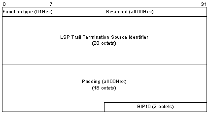
Figure 1-1 OAM CV packet format
Table 1-1 describes the fields of the OAM CV packet.
Table 1-1 Description on the fields of the OAM CV packet
|
Field |
Description |
|
Function type |
Packet type, with 0x01 being the CV packet |
|
Reserved |
Reserved field |
|
LSP Trail Termination Source Identifier |
TTSI, uniquely identifying an LSP in a network. It consists of 16-byte ingress LSR ID and 4-byte LSP ID. For IPv4, the first 10 bytes of ingress LSR ID are padded with 0x00, the following two bytes are padded with 0xFF, and the last four bytes are IPv4 address. |
|
Padding |
Padded field |
|
BIP16 |
Packet checksum |
II. OAM FFD packets
Like CV packets, you also can verify the LSP connectivity by checking the OAM FFD packets sent from the ingress node of an LSP arrive at the egress node. Figure 1-2 shows the format of the OAM FFD packet.
Compared with a CV packet, a FFD packet has additional 1-byte frequency information. The transmission frequency is set to 1 second for the CV packet. For the FFD packet, multiple transmission frequencies are supported, including 10ms, 20ms, 50ms, 100ms, 200ms, and 500ms.
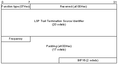
Figure 1-2 OAM FFD packet format.
Table 1-2 describes the fields of the OAM FFD packet.
Table 1-2 Description on the fields of the OAM FFD packet
|
Field |
Description |
|
Function type |
Packet type, with 0x07 being the FFD packet |
|
Reserved |
Reserved field |
|
LSP Trail Termination Source Identifier |
TTSI. Refer to Table 1-1. |
|
Frequency |
Transmission frequency for FFD packet |
|
Padding |
Padded field |
|
BIP16 |
Packet checksum |
III. OAM FDI packets
OAM FDI packets are used by the upstream node of an LSP to notify the egress node of defect information. In addition, when auto protocol is enabled, the ingress node notifies the egress node with OAM FDI packets that it should stop defect verification. Figure 1-3 shows the format of the OAM FDI packet.
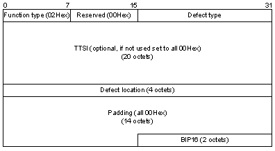
Figure 1-3 OAM FDI packet format
Table 1-3 describes the fields of the OAM FDI packet.
Table 1-3 Description on the fields of the OAM FDI packet
|
Field |
Description |
|
Function type |
Packet type, with 0x02 being the FDI packet |
|
Reserved |
Reserved field |
|
Defect type |
Type of LSP defects |
|
TTSI |
LSP identifier, refer to Table 1-1. Without TTSI, each byte of the field is padded with 0x00. |
|
Defect location |
Information about defect location |
|
Padding |
Padded field |
|
BIP16 |
Packet checksum |
IV. OAM BDI packets
OAM BDI packets are used by the egress node to notify the ingress node of defect information through a reverse channel after it finds LSP defects. Figure 1-4 shows the format of the OAM BDI packet.
The implications of the fields of the OAM BDI packet are the same as that of the OAM FDI packet, as shown in Table 5-3.

Figure 1-4 OAM BDI packet format
1.1.3 MPLS OAM Capabilities
I. Basic capability
MPLS OAM basic capability refers to connectivity verification.
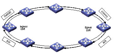
Figure 1-5 Networking diagram for MPLS OAM connectivity verification
As shown in Figure 1-5, procedure of connectivity verification follows:
1) The ingress node sends CV/FFD packets through the LSP to be verified to the egress node.
2) By comparing the received information such as packet type, frequency and TTSI with the locally recorded values that should be received, the egress node checks the packets are received properly, and takes statistics for the right packets and wrong packets received in the verification period so as to monitor the LSP connectivity.
3) Once it detects LSP defects, the egress node analyzes the types of LSP defects and transmits the BDI packet with defect information to the ingress node through a reverse channel. In this way, the ingress node can get the defect state immediately. If a protection group is configured properly, the corresponding protection switching would also be triggered.
When configuring MPLS OAM basic capability, you need to bind a reverse channel to the LSP to be verified. A reverse channel is an LSP which has an ingress node and an egress node contrary to the LSP to be verified. There are two types of reverse channels:
l Dedicated reverse channel: Each forward LSP has its own reverse channel. This means is rather stable but may incur wasted resources.
l Shared reverse channel: Multiple forward LSPs have a reverse channel in common. All the LSPs transmit BDI packets through this LSP. This means reduces wasted resources. However, the shared reverse channel may be congested when defects are detected on multiple forward LSPs at the same time. Configuring additional acknowledgement information for BDI packets is required in order for the ingress node to distinguish which forward LSP has defects depending on the BDI packets received. For example, TTSI is configured for the MPLS OAM. As a result, a BDI packet can carry the TTSI information of the LSP to be verified, which is useful for checking the BDI packet is necessary.
II. Protection switching
Protection switching (PS) is designed to establish the corresponding protection LSP (secondary LSP) for the primary LSP. The primary LSP and the secondary LSP constitute a protection group. In protection switching mode, once the primary LSP fails, data flows can be switched to the secondary LSP rapidly, significantly improving the reliability of networks.
In real world, you also can manually input some switching commands as required to switch from the primary LSP to the secondary LSP, or vice versa. Manual switching and signaling switching are prioritized. For manual switching, the switching takes effect only when its priority is higher than the priority of the current signaling.
For PS, four modes are supported: 1:1 protection, 1+1 protection, share mesh protection and packet 1+1 protection.
l 1:1 protection: Two LSPs in primary/secondary mode are available between the ingress node and the egress node. In general, data is transported over the primary LSP; when the ingress node detects some defect on the primary LSP through verification mechanism (for example, OAM) and needs to run protection switching, it switches data to the secondary LSP and keeps on transmission.
l 1+1 protection: Two LSPs in primary/secondary mode are available between the ingress node and the egress node. In general, the ingress node sends the same data packets to these two LSPs at the same time; but the egress node only receives the data from the primary LSP. When the egress node detects some defect on the primary LSP, it stops receiving data from the primary LSP and switches to the secondary LSP to receive data.
l Share mesh protection: This protection mode is designed for saving bandwidth in the mesh network topology. In short, an LSP is used as the secondary LSP for multiple LSPs. When any LSP fails, data packets to be transported over the LSP are switched to the secondary LSP. The triggering and switching mechanisms of this mode are similar to 1:1 protection.
l Packet 1+1 protection: This protection mode is similar to 1+1 protection. The difference between them is that for packet 1+1 protection, the ingress node sends packets with order labels through the primary LSP and the secondary LSP to the egress node. For the packets with the same order label, the egress node receives the one arrived in advance and drops the other. This protection mode is rather complex and difficult to control.
Now, only 1:1 protection is supported.
1.1.4 References
For more information about MPLS OAM, refer to:
l ITU-T Recommendation Y.1710: Requirements for Operation & Maintenance functionality for MPLS networks
l ITU-T Recommendation Y.1711: Operation & Maintenance mechanism for MPLS networks
l ITU-T Recommendation Y.1720: Protection switching for MPLS networks
1.2 MPLS OAM Configuration
1.2.1 MPLS OAM Configuration Task List
|
Task |
Remarks |
|
Required |
|
|
Required |
1.2.2 Configuring MPLS OAM Basic Capability
I. Configuration Prerequisites
1) Application environment
MPLS OAM basic verification capability is designed to monitor the connectivity state of an MPLS network, and verify and pinpoint the defects in the MPLS network. To verify the connectivity of the MPLS network, you should configure the MPLS OAM function for LSPs.
2) Configuration preparation
To configure MPLS OAM basic capability, perform the following tasks:
l Configure MPLS basic capabilities, refer to MPLS Configuration.
l Configure static LSPs, refer to MPLS Configuration.
3) Data preparation
To configure MPLS OAM basic capability, prepare the following data:
Table 1-4 Data preparation
|
Number |
Data |
|
1 |
The static LSP to be verified |
|
2 |
For ingress node, LSP ID of the static LSP to be verified For egress node, the ingress LSR ID and LSP ID of the static LSP to be verified |
|
3 |
The static LSP of the reverse channel |
|
4 |
MPLS OAM parameters, for instance, verification packet type and FFD transmission frequency |
If the ingress node adopts a shared reverse channel, the No. 3 data in the above table is omitted.
II. Configuration Procedure
Follow these steps to configure MPLS OAM basic capability:
|
To do... |
Use the command... |
Remarks |
|
Enter system view |
system-view |
— |
|
Enable MPLS OAM |
mpls oam |
Required |
|
Configure MPLS OAM parameters for the ingress node |
mpls oam ingress lsp-name lsp-name lsp-id lsp-id [ type { cv | ffd [ frequency ffd-fre ] } ] [ backward-lsp share | lsp-name rev-lsp-name ] |
Required |
|
Enable OAM for the ingress node |
mpls oam ingress enable { all | lsp-name lsp-name } |
Required |
|
Configure MPLS OAM parameters for the egress node |
mpls oam egress lsp-name lsp-name lsr-id lsr-id lsp-id lsp-id [ type { cv | ffd [ frequency ffd-fre ] } ] [ backward-lsp rev-lsp-name [ private | share ] ] |
Required |
|
Enable OAM for the egress node |
mpls oam egress enable { all | lsp-name lsp-name } |
Required |
& Note:
l This operation also can be used for modifying MPLS OAM parameters.
l The configuration of MPLS OAM parameters takes effect only after the MPLS OAM function is enabled. You must first enable the MPLS OAM function on the ingress node and then on the egress node. Otherwise, the egress node will generate an alert.
1.2.3 Configuring a Protection Group
I. Configuration Prerequisites
1) Application environment
In an environment with higher demand on network performance, a protection channel is reserved so that transmission of data flows can be restored rapidly after the primary LSP failed.
2) Configuration preparation
To configure a protection group, perform the following tasks:
l Enable MPLS;
l Create the primary static LSP and the secondary static LSP.
3) Data preparation
To configure a protection group, prepare the following data:
Table 1-5 Data preparation
|
Number |
Data |
|
1 |
Protection group ID |
|
2 |
Name of the primary LSP in the protection group |
|
3 |
Name of the secondary LSP in the protection group |
|
4 |
Protection group parameters, for instance, Hold off time, switch back mode and WTR time |
Note that:
1) This operation also can be used for modifying protection group parameters.
2) Switch back means that after the primary LSP recovered from a fault, data flows are switched from the secondary LSP back to the primary LSP.
3) FIB entries are not updated when data flows are switched from the primary LSP to the secondary LSP. By querying the primary and secondary LSPs and the protection group, you can view the forwarding information of the current LSP (for instance, next hop, outbounding interface).
4) The data flow is on the primary LSP if both the primary and secondary LSPs in one protection group fail.
l When the primary LSP is in the up/no-defect state and the secondary LSP is in the down, in-defect, or down/in-defect state, the data flow is on the primary LSP. If the primary LSP then turns into the down, in-defect, or down/in-defect state, no switching will take place.
l When the primary LSP is in the down, in-defect or down/in-defect state and the secondary LSP is in the up/no-defect state, the data flow is on the secondary LSP. If the secondary LSP then turns into the down, in-defect, or down/in-defect state, the data flow will be switched to the primary LSP though the latter is not operational.
5) When you delete a protection group where the data flow is on the secondary LSP, the data flow will be switched to the primary LSP before the group is deleted, even if the primary LSP is not operational.
6) If no protection group is configured, the manually-configured secondary LSP will not have a corresponding LSP forwarding entry.
II. Configuration Procedure
Follow these steps to configure a protection group:
|
To do... |
Use the command... |
Remarks |
|
Enter system view |
system-view |
— |
|
Configure a protection group for the specified primary LSP |
mpls protect-switch protect-id work-lsp lsp-name protect-lsp lsp-name [ holdoff holdoff-time ] [ mode revertive ] [ wtr wtr-time ] mpls protect-switch protect-id work-lsp lsp-name protect-lsp lsp-name [ holdoff holdoff-time ] mode non-revertive |
Required |
|
Enable external protection switch |
mpls protect-switch manual { protect-lsp | work-lsp } protect-id |
Optional |
|
Display information about the protection group |
display mpls protect-switch { all | protect-id } [ verbose | brief ] |
In any view |
1.3 Displaying and Debugging MPLS OAM Basic Capability
|
To do… |
Use the command... |
Remarks |
|
Display MPLS OAM information on the ingress node |
display mpls oam ingress { all | lsp-name lsp-name } [ slot slot-id | verbose ] |
Alailable in any view |
|
Display MPLS OAM information on the egress node |
display mpls oam egress { all | lsp-name lsp-name } [ slot slot-id | verbose ] |
Alailable in any view |
|
Display information about OAM packets received on the ingress node |
display mpls oam ingress receive-packet { all | bdi | error } slot slot-id |
Alailable in any view |
|
Display information about OAM packets sent from the ingress node |
display mpls oam ingress send-packet { all | ap-fdi | cv | error | ffd } slot slot-id |
Alailable in any view |
|
Display information about OAM packets received on the egress node |
display mpls oam egress receive-packet { all | ap-fdi | cv | error | fdi | ffd } slot slot-id |
Alailable in any view |
|
Display information about OAM packets sent from the egress node |
display mpls oam egress send-packet { all | bdi | error } slot slot-id |
Alailable in any view |
|
Clear the statistics of all OAM packets on the ingress node |
reset mpls oam packet-statistics ingress { all | lsp-name lsp-name } |
Alailable in user view |
|
Clear the statistics of all OAM packets on the egress node |
reset mpls oam packet-statistics egress { all | lsp-name lsp-name } |
Alailable in user view |
|
Clear the statistics of OAM packets for the specified interface card |
reset mpls oam packet-statistics slot slot-id |
Alailable in user view |
Executing the above mentioned commands, you will view the following results:
l Basic LSP information, including LSP name, LSP state, ingress LSR ID;
l Basic OAM information, including LSP name, TTSI, verification packet type, transmission frequency;
l OAM verification information, including type of the packets to be transmitted, transmission period, verification state and defect state. When the LSP works properly, the verification state is Start and the defect state is No-defect;
l OAM reverse channel information, including share type, configuration information;
l Statistics of OAM packets received/sent on the ingress node;
l Statistics of OAM packets received/sent on the egress node.
1.4 Typical MPLS OAM Configuration Example
I. Network requirements
As shown in Figure 1-6, two static LSPs (in primary/secondary mode) and a shared reverse channel are available between Switch A and Switch B. Once it detects connectivity defects on the primary LSP, the egress node Switch C notifies the ingress node Switch A of defect verification results, and switches data flows to the secondary LSP.
In this case, only Switch A and Switch C need to support MPLS OAM, Switch B, Switch D and Switch E do not.
1) Configuration preparation
l At least two static LSPs are available between the ingress node and the egress node to constitute a protection group. At the same time, a reverse static LSP from the egress node to the ingress node is available for the egress node to notify connectivity defects.
l You need to configure a protection group, and specify the protection group ID, protection switching delay, switch back mode and switch back wait time.
l You need to enable MPLS OAM globally on the ingress node and the egress node.
l You need to configure MPLS OAM parameters for the LSP to be verified and enable the MPLS OAM function on the ingress node.
l You need to configure MPLS OAM parameters for the LSP to be verified and enable the MPLS OAM function on the egress node
2) Data preparation
To complete the configuration, you need to specify the following data:
l IP addresses of VLAN interfaces of various switches and names of various static LSPs, as shown in Figure 5-6.
l Static LSPs borrow the loopback addresses of various switches. The destination IP address of the primary and secondary LSPs is 3.3.3.3/32 and the destination IP address of the reverse channel is 1.1.1.1/32.
l In a protection group, the switch back delay is set to 10, that is, 1 second; the switch back mode is revertive; the switch back wait time is 20, that is, 10 minutes.
l The type of verification packet to be sent is set to CV and the transmission period is the defaulted 1 second.
l The reverse channel is set to share.
II. Networking diagram
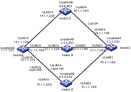
Figure 1-6 Networking diagram for configuring OAM and PS basic capabilities
III. Configuration procedure
1) Configure IP addresses for various interfaces
As shown in Figure 1-6, configure the IP addresses and masks of various interfaces, including various loopback interfaces. The detailed configuration steps are omitted.
2) Configure the IGP protocol
Enable OSPF on all switches and advertise their own routes. The detailed configuration steps are omitted.
After the above configurations are completed, switches should interoperate to each other on the network layer. You can issue the display ip routing-table command on switches to view the routing table.
3) Configure MPLS OAM and static LSPs
As shown in Figure 1-6, configure the primary static LSP LspAtC and the secondary static LSP LspAtCp on Switch A; configure a shared reverse channel LspCtA on Switch C.
4) Configure MPLS OAM for Switch A
# Enable MPLS OAM globally.
<SwitchA> system-view
[SwitchA] mpls oam
# Configure OAM parameters for the ingress node.
[SwitchA] mpls oam ingress lsp-name LspAtCw lsp-id 100
[SwitchA] mpls oam ingress lsp-name LspAtCp lsp-id 200
# Configure a protection group.
[SwitchA] mpls protect-switch 1 work-lsp lspAtCw protect-lsp lspAtCp holdoff 10 mode revertive wtr 20
Using the display mpls protect-switch all command, you will see the following information:
[SwitchA] display mpls protect-switch all
-----------------------------------------------------------------------
Protection-Switching Information
-----------------------------------------------------------------------
PROTECT-ID Dft-W Dft-P Ctrl-W Ctrl-P SwitchRst
1 No-defect No-defect Up Up W
# Enable MPLS OAM on the ingress node.
[SwitchA] mpls oam ingress enable all
5) Configure MPLS OAM for Switch C
# Enable MPLS OAM globally.
<SwitchC> system-view
[SwitchC] mpls oam
# Configure OAM parameters for the egress node.
[SwitchC] mpls oam egress lsp-name lspAtCw lsr-id 1.1.1.1 lsp-id 100 backward-lsp lspCtA share
[SwitchC] mpls oam egress enable lsp-name lspAtCw
[SwitchC] mpls oam egress lsp-name lspAtCp lsr-id 1.1.1.1 lsp-id 200 backward-lsp lspCtA share
[SwitchC] mpls oam egress enable lsp-name lspAtCp
After completing the above configurations, you can view information about the current LSP and OAM and statistics of OAM verification packets on Switch A and Switch C.
The following takes the display on Switch C as an example.
# Display configuration information about the current LSP and OAM.
<SwitchC> display mpls oam egress all verbose
--------------------------------------------------------------------------
Verbose information about the 1st OAM at egress
--------------------------------------------------------------------------
lsp basic information: oam basic information:
--------------------------------------------------------------------------
Lsp-name : lspAtCw Oam-Index : 1024
Lsp signal status : Up Oam select board : 2
Lsp incoming Label : 3 Enable-state : --
Lsp ingress lsr-id : 1.1.1.1 Auto-protocol :Disable
Auto-overtime (s) : 0
Ttsi/lsr-id : 1.1.1.1
Ttsi/lsp-id : 100
oam detect information: oam backward information:
--------------------------------------------------------------------------
Type : CV Share attribute : Share
Frequency : 1 s Lsp-name : lspCtA
Detect-state : Start Lsp-state : Up
Defect-state : No-defect
--------------------------------------------------------------------------
Verbose information about the 2nd OAM at egress
--------------------------------------------------------------------------
lsp basic information: oam basic information:
--------------------------------------------------------------------------
Lsp-name : lspAtCp Oam-Index : 1025
Lsp signal status : Up Oam select board : 2
Lsp incoming Label : 3 Enable-state : --
Lsp ingress lsr-id : 1.1.1.1 Auto-protocol : Disable
Auto-overtime (s) : 0
Ttsi/lsr-id : 1.1.1.1
Ttsi/lsp-id : 200
oam detect information: oam backward information:
--------------------------------------------------------------------------
Type : CV Share attribute : Share
Frequency : 1 s Lsp-name : lspCtA
Detect-state : Start Lsp-state : Up
Defect-state : No-defect
--------------------------------------------------------------------------
Total Oam Num: 2
Total Start Oam Num: 2
Total Defect Oam Num: 0
# Display the statistics of verification packets received on the egress node.
<SwitchC> display mpls oam egress receive-packet all slot 2
--------------------------------------------------------------------------
CV Packet FFD Packet FDI Packet AP-FDI Packet Error Packet
--------------------------------------------------------------------------
467 0 0 0 0
6) Verify the configuration
Shutdown interface VLAN12 of Switch B. At this point, the primary LSP on Switch A detects a defect.
Using the display mpls protect-switch all command on Switch A, you will see that data flows are switched to the secondary LSP.
[SwitchA] display mpls protect-switch all
-----------------------------------------------------------------------
Protection-Switching Information
-----------------------------------------------------------------------
PROTECT-ID Dft-W Dft-P Ctrl-W Ctrl-P SwitchRst
1 Defect No-defect Up Up P
1.5 Troubleshooting MPLS OAM
1.5.1 Failure to Enable OAM on the Ingress Node
I. Symptom
When you execute the mpls oam ingress enable [ lsp-name lsp-name ] command on the ingress node, the message “% Warning: Invalid LSP name.” displays.
II. Solution
According to the message, you will see that the OAM parameters for the ingress node are not configured rightly. To solve the problem, you can:
l Execute the mpls oam ingress lsp-name lsp-name lsp-id lsp-id [ type { cv | ffd [ frequency ffd-fre ] } ] [ backward-lsp share | lsp-name rev-lsp-name ] command on the ingress node to configure OAM parameters for the LSP to be verified.
l Execute the display mpls oam ingress [ all | lsp lsp-name ] command to display the configured OAM parameters.
l Execute the mpls oam ingress enable [ all | lsp-name lsp-name ] command to enable the MPLS OAM function.
1.5.2 Failure to Enable OAM on the Egress Node
I. Symptom
When you execute the mpls oam egress enable [ lspname lsp-name ] command on the egress node, the message “% Warning: Invalid LSP name.” displays.
II. Solution
According to the message, you will see that the OAM parameters for the egress node are not configured rightly. To solve the problem, you can:
l Execute the mpls oam egress lsp-name lsp-name lsr-id ingress-lsr-id lsp-id lsp-id } type { cv | ffd [ frequency ffd-fre ] } ] [ backward-lsp rev-lsp-name [ private | share ] ] command on the egress node to configure OAM parameters for the LSP to be verified.
l Execute the display mpls oam egress [ all | lspname lsp-name ] command to display OAM parameters configured in step 1.
l Execute the mpls oam egress enable [ all | lsp-name lsp-name ] command to enable the MPLS OAM function.
1.5.3 Abnormal Verification Occurs on the Egress Node
I. Symptom
The network works properly. When you execute the display mpls oam egress [ all | lspname lsp-name ] verbose command on the egress node, the defect-sate field displays dLocv or dUnknown.
II. Solution
The reason for this problem may come from:
l The ingress node does not enable OAM.
l The ingress LSR ID and LSP ID of the LSP to be verified are not configured rightly on the ingress node and the egress node.
l OAM parameters like verification packet type and transmission frequency configured on the ingress node and the egress node are not consistent.
To solve this problem, you can:
l When you execute the display mpls oam ingress [ all | lsp-name lsp-name ] verbose command, the Enable-state field displays Manual disable, meaning that the ingress node does not enable OAM. In this case, you should execute the mpls oam ingress enable [ all | lsp-name lsp-name ] command to enable OAM on the ingress node.
l If OAM is enabled on the ingress node, execute the display mpls oam ingress [ all | lsp-name lsp-name ] verbose command and the display mpls oam egress [ all | lspname lsp-name ] verbose command to display the OAM configuration for the ingress node and the egress node respectively. If the ingress LSR ID and LSP ID of the LSP to be verified, verification packet type and transmission frequency are inconsistent, use the corresponding configuration command to configure them properly and reenable OAM.
1.5.4 The Defect State of the Ingress Node is Different from that of the Egress Node
I. Symptom
When you execute the display mpls oam egress [ all | lsp-name lsp-name ] verbose command on the egress node, the Defect-sate field displays dLocv; while you execute the display mpls oam ingress [ all | lsp-name lsp-name ] verbose command on the ingress node, the defect-sate field displays No-defect.
II. Solution
The reason for this problem may come from:
l The reverse channel is not configured or down. So the egress node cannot notify the ingress node of defect verification results.
l The reverse channel specified by the ingress node is different from that specified by the egress node.
To solve this problem, you can:
l Execute the display mpls oam egress [ all | lsp-name lsp-name ] verbose command. If the lsp-name field is null in the oam backward information, which means the reverse channel is not configured. In this case, you should use the OAM configuration command to configure a reverse channel for the LSP to be verified.
l Both nodes are configured with a reverse channel, but the lsp-state field is down in the oam backward information. In this case, you should modify MPLS configuration and make the reverse channel up, or reuse OAM configuration commands to configure an up reverse channel for the LSP to be verified.
l The reverse channel of the egress node is up, but it is different from that configured on the ingress node. In this case, you should configure the reverse channel properly on the egress node and the ingress node.
1.5.5 The Defects of the Ingress Node cannot Trigger Protection Switching
I. Symptom
Protection switching is enabled. When you execute the display mpls oam ingress [ all | lsp-name lsp-name ] verbose on the ingress node, the defect-state field displays In defect; while you execute the display mpls protect-switch [ protect-id | all ] verbose command through command line, the Switching Result field displays Working LSP.
II. Solution
The reason for this problem may come from:
l The primary LSP is not the one for OAM defect verification.
l The secondary LSP also has defects and data flows are not switched.
l Holdoff is not zero. You need to wait a period of time before triggering protection switching.
l External switching command restricts the transmission of data flows to the primary LSP.
To solve this problem, you can:
l Execute the display mpls protect-switch [ all | protect-id ] verbose command. If the Working LSP User Plane Status is No-defect, which means the primary LSP configured in the protection group is not the one for OAM defect verification. In this case, you should use OAM ingress node and egress node configuration commands to configure OAM parameters for the primary LSP in the protection group and restart defect verification, or use the protection group configuration command to configure a protection group for the LSP for defect verification.
l If the Working LSP User Plane Status field is In defect and the Protect LSP User Plane Status field is In defect, which means the secondary LSP in the protection group has defects. In this case, you should use the protection group command to configure another perfect LSP and the primary LSP to constitute a protection group.
l If the above two conditions are not met, view the Holdoff field. If the Holdoff is not zero, which means Holdoff does not expire. This is not a fault. When the primary LSP fails, data flows are switched to the secondary LSP only when it is always available after Holdoff time. To trigger protection switching immediately after the primary LSP fails, you should use the protection group command to set Holdoff to zero.
1.5.6 The Primary LSP Recovered from a Defect, but the Protection Group cannot Switch back
I. Symptom
When you execute the display mpls protect-switch protect-id command, the Switch Rst field is P. In this case, data flows are still transmitted over the secondary LSP, even the primary LSP recovered from a defect.
II. Solution
The reason for this problem may come from:
l The protection group is in non-revertive mode.
l The switch back wait time is longer.
l The external switching command switches data flows to the secondary LSP for transmission by force. It has a higher priority.
To solve this problem, you can:
l Execute the display mpls protect-switch [ protect-id | all ] verbose command. If the Revertive Mode field is Non-revertive, the protection group is in non-revertive mode. This is not a fault. To trigger switch back after the primary LSP recovered from a defect, you should use the mpls protect-switch command to configure the protection group as revertive mode.
l If the protection group is in revertive mode and the WTR field is not zero, which means WTR does not expire. This is not a fault. After the primary LSP recovered from a defect, data flows will be switched back to the primary LSP in WTR time. To trigger switch back after the primary LSP recovered from a defect, you should use the mpls protect-switch command to set WTR to zero.