- Table of Contents
- Related Documents
-
| Title | Size | Download |
|---|---|---|
| 04-MPLS L3VPN Configuration | 1.26 MB |
Table of Contents
Chapter 1 MPLS L3VPN Configuration
1.1.2 MPLS L3VPN Implementation
1.1.3 Nested MPLS L3VPN Implementation
1.1.4 Hierarchical MPLS L3VPN Implementation
1.1.5 Introduction to OSPF Multi-Instance
1.1.6 Introduction to Multi-Role Host
1.2.1 Configuring Various Kinds of Routers
1.3 Displaying and Debugging MPLS L3VPN
1.4 Typical MPLS L3VPN Configuration Examples
1.4.1 Integrated MPLS L3VPN Configuration Example
1.4.2 Extranet Configuration Example
1.4.3 Hub&Spoke Configuration Example
1.4.4 CE Dual-home Configuration Example
1.4.5 Cross-domain MPLS L3VPN Configuration Example
1.4.6 Cross-Domain MPLS L3VPN Configuration Example — Option C
1.4.7 Hierarchical MPLS L3VPN Configuration Example
1.4.8 OSPF Multi-instance Sham-link Configuration Example
1.4.9 Nested MPLS L3VPN Configuration Example
1.4.10 OSPF Multi-instance CE Configuration Example
1.4.11 Multi-Role Host Configuration Example
1.4.12 FIB Entry Application Configuration Example
1.5 Troubleshooting MPLS L3VPN Configuration
Chapter 1 MPLS L3VPN Configuration
When configuring MPLS L3VPN, go to these sections for information you are interested in:
l Displaying and Debugging MPLS L3VPN
l Typical MPLS L3VPN Configuration Examples
l Troubleshooting MPLS L3VPN Configuration
1.1 MPLS L3VPN Overview
Traditional VPN, for which Layer 2 tunneling protocols (L2TP, L2F and PPTP, and so on.) or Layer 3 tunnel technology (IPSec, GRE and so on.) is adopted, is a great success and is therefore widely used. However, along with the increase of the size of VPNs, the deficiency of traditional VPN in such aspects as expansibility and manageability becomes more and more obvious. In addition, QoS (Quality of Service) and security are also the difficult problem for traditional VPN.
Using the MPLS technology, service providers can implement the IP-based VPN services easily and enable their networks to meet the expansibility and manageability requirement for VPN. The VPN constructed by using MPLS also provides the possibility for the implementation of value-added service. Multiple VPNs can be formed from a single access point, and each VPN represents a different service, making the network able to transmit services of different types in a flexible way.
The H3C S9500 series routing switches provide full MPLS L3VPN networking capabilities:
l Address isolation, allowing the overlap of addresses of different VPNs and public networks.
l Supporting MBGP advertising VPN routing information through public networks, establishing MPLS L3VPN.
l Forwarding VPN data stream over MPLS LSP.
l Providing MPLS VPN performance monitoring and fault detecting tools.
1.1.1 MPLS L3VPN Model
I. MPLS L3VPN model
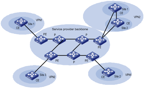
As shown in Figure 1-1, MPLS L3VPN model contains three parts: CE, PE and P.
l CE (Customer Edge) device: It is a composing part of the customer network, which is usually connected with the service provider directly through an interface. It may be a router or a switch which cannot sense the existence of VPN.
l PE (Provider Edge) device: It is an edge device of the provider network, connecting with CE devices directly. In MPLS network, a PE device processes all the operations for VPN. PE needs to possess MPLS basic forwarding capability.
l P (Provider) device: It is the backbone router in the provider network, which is not connected with CE directly. P router needs to possess MPLS basic forwarding capability.
The classification of CE and PE mainly depends on the range for the management of the provider and the customer, and CE and PE are the edges of the management ranges.
II. Nested MPLS L3VPN model
In a basic MPLS L3VPN model, the PEs are in the network of the service provider and are managed by the service provider.
When a VPN user wants to subdivide the VPN into multiple VPNs, the traditional solution is to configure these VPNs directly on the PEs of the service provider. This solution is easy to implement, but has the following disadvantages: the number of the VPNs carried on PEs may increase rapidly; the operator may have to perform more operations when required by a user to adjust the relation between the user's internal VPNs. These disadvantages not only increase the network operating cost, but also bring relevant management and security issues.
The nested VPN is a better solution. Its main idea is to transfer VPNv4 route between PE and CE of common MPLS L3VPN such that user themselves can manage their internal VPN division, and the service provider can be saved from participating into users' internal VPN management.
The following figure shows the network model for nested VPN:

Figure 1-2 Network model for nested MPLS L3VPN
III. Basic concepts in MPLS L3VPN
1) VPN-instance
VPN-instance is an important concept in VPN routing in MPLS. In an MPLS VPN implementation, each site corresponds to a specific VPN-instance on PE (their association is implemented by binding VPN-instance to the VLAN interface). If subscribers on one site belong to multiple VPNs, then the corresponding VPN-instance includes information about all these VPNs.
Specifically, such information should be included in VPN-instance: label forwarding table, IP routing table, the interfaces bound with VPN-instance, and the management information (RD, route filtering policy, member interface list, and so on). It includes the VPN membership and routing rules of this site.
PE is responsible for updating and maintaining the relationship between VPN-instance and VPN. To avoid data leakage from the VPN and illegal data entering into the VPN, each VPN-instance on the PE has an independent set of routing table and label forwarding table, in which the forwarding information of the message is saved
2) MBGP
MBGP (multiprotocol extensions for BGP-4, see RFC2283) propagates VPN membership information and routes between PE routers. It features backward compatibility: It not only supports traditional IPv4 address family, but also supports other address families, for example, VPN-IPv4 address family. MP-BGP ensures that VPN private routes are only advertised within VPNs, as well as implementing communication between MPLS VPN members.
3) VPN-IPv4 address
VPN is just a private network, so it can use the same IP address to indicate different sites. But the IP address is supposed as unique when MP-BGP advertises CE routes between PE routers, so routing errors may occur for the different meaning in two systems. The solution is to switch IPv4 addresses to VPN-IPv4 address to generate globally unique addresses before advertising them, so PE routers is required to support MP-BGP.
A VPN-IPv4 address consists of 12 bytes, and the first eight bytes represent the RD (Route Distinguisher), which are followed by a 4-byte IPv4 address. The service providers can distribute RD independently. However, their special AS (Autonomous System) number must be taken as a part of the RD. After being processed in this way, even if the 4-byte IPv4 address contained in VPN-IPv4 address has been overlapped, the VPN-IPv4 address can still maintain globally unique. RD is only used within the carrier network to differentiate routes. When the RD is 0, a VPN-IPv4 address is just a IPv4 address in general sense.
The route received by PE from CE is the IPv4 route that needs to be redistributed into VPN-instance routing table, and in this case a RD needs to be added. It is recommended that the same RD be configured for all routes from the same user site.
IV. VPN Target attribute
VPN Target attribute is one of the MBGP extension community attributes and is used to limit VPN routing information advertisement. It identifies the set of sites that can use some route, namely by which Sites this route can be received, and the PE router can receive the route transmitted by which Sites. The PE routers connected with the site specified in VPN Target can all receive the routes with this attribute.
For PE routers, there are two sets of VPN Target attributes: one of them, referred to as Export Targets, is added to the route received from a direct-connect site in advertising local routes to remote PE routers. And the other one, known as Import Targets, is used to decide which routes can be imported into the routing table of this site in receiving routes from remote PE routers.
When matching the VPN Target attribute carried by the route to filter the routing information received by the PE router, if the export VPN target set of the received route contains identical items with the import VPN target set of the local end, the route is imported into the VPN routing table and then advertised to the connected CE . Otherwise, the route will be rejected.
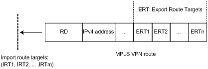
Figure 1-3 Route filtering through matching VPN Target attribute
& Note:
The routes for other VPNs will not appear in the VPN's routing table by using VPN Target attribute to filter routing information received at PE router, so the CE-transmitted data will only be forwarded within the VPN.
V. Routing policy
If the advertisement of routing information needs to be controlled in a more accurate manner than using egress extended community attributes only, you can use an outgoing routing policy.
In the outgoing routing policy you can set specific extended community attributes for specific routes to be advertised.
After creating a VPN instance, you can choose whether to configure an outgoing routing policy for it.
1.1.2 MPLS L3VPN Implementation
MPLS L3VPN works on this principle: It uses BGP to propagate VPN private routing information on carrier backbone network, and uses MPLS to forward VPN service traffic.
The following are introductions to MPLS L3VPN implementation from two aspects: advertising VPN routing information and forwarding VPN packets.
I. Advertising VPN routing information
Routing information exchange has the following four types:
1) Between CE and PE
A PE router can learn routing information about the CE connected to it through static route, RIP (supporting multi-instance), OSPF (supporting multi-instance) or EBGP, and imports it in a vpn-instance.
2) Between ingress PE and egress PE
The ingress PE router uses MP-BGP to send information across public network: It advertises routing information learned from CE to the egress PE router (with MPLS label) and learns the CE routing information learned at the egress PE router.
The internal connectivity among the VPN internal nodes is ensured through enabling IGP (for example, RIP and OSPF) or configuring static routes on the PEs.
3) LSP setup between PEs
LSPs must be set up between PEs for VPN data traffic forwarding with MPLS LSP. The PE router which receives packets from CE and create label protocol stack is called Ingress LSR, while the BGP next hop (Egress PE router) is Egress LSR. Using LDP to create fully connected LSPs among PEs.
4) Between PE and CE
A CE can learn remote VPN routes from the PE connected through static routes, RIP, OSPF or EBGP.
With above-mentioned steps, reachable routes can be established between CEs, for transmission of VPN private routing information over public network.
II. Forwarding VPN packets
On the ingress PE, two-layer label stack is formed for each VPN packet:
Interior-layer label, also called MPLS label, is at the bottom of the label stack and distributed by M-BGP when the egress PE advertises routing information (in VPN forwarding table) to ingress GE. When VPN packets from public network reach the CE, they can be forwarded from the designated interface to the designated CE or site by searching for the target MPLS forwarding table according to the labels contained.
Exterior-layer label, known as LSP initialization label, distributed by MPLS LDP, is at the top of the label stack and indicates an LSP from the ingress PE to egress PE. By the switching of exterior-layer label, VPN packets can be forwarded along the LSP to the peer PE.
Figure 1-4 illustrates the details:
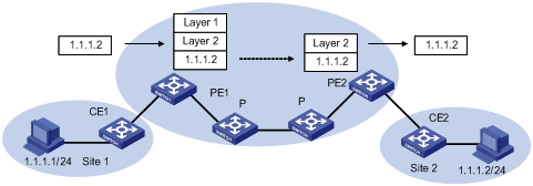
Figure 1-4 Forwarding VPN packets
1) Site 1 sends an IPv4 packet with the destination address 1.1.1.2 of to CE1. CE1 looks up the IP routing table for a matched entry and sends the packet to PE1 according to the matched entry.
2) Depending on the interface the packet reaches and the destination of it, PE1 looks up the VPN-instance entry to obtain interior-layer label, exterior-layer label, BGP next hop (PE2), and output interfaces. After the establishment of labels, PE1 forwards MPLS packets to the first P of LSP through output interface.
3) Each P router on LSP forwards MPLS packets using exterior-layer label to the penultimate-hop router, namely the P router before PE2. The penultimate-hop router extracts the exterior-layer and sends MPLS packet to PE2.
4) PE2 looks up in the MPLS forwarding table according to the interior-layer label and destination address to determine the egress interface for labeling operation and the packet. It then extracts the interior-layer label and forwards through the egress interface the IPv4 packet to CE2.
5) CE2 looks up in the routing table and sends the packet in normal IPv4 packet forwarding mode to the site2.
1.1.3 Nested MPLS L3VPN Implementation
When implementing a nested MPLS L3VPN, pay attention to the following items:
l No address overlap is allowed between user's internal sub-VPNs.
l To ensure the VPN routing information is correctly advertised over the backbone network, the VPN-Targets of the user VPN and the internal sub-VPNs cannot be overlapped and must be specified by the service provider.
l The provider PE and the customer PE must be directly connected and cannot exchange VPNv4 route in Multihop-EBGP mode.
Before configuring a nested MPLS L3VPN, you must complete the following tasks:
l Configuring IGP on the MPLS backbone network (including provider PE and P routers) to implement the IP connectivity on the backbone network.
l Configuring basic MPLS capability on the MPLS backbone network.
l Configuring MPLS LDP and setting up LDP LSP on the MPLS backbone network.
l Configuring BGP on the MPLS backbone network (create IBGP peers between provider PEs).
l Configuring basic MPLS capability on user-end network (including customer PEs).
1.1.4 Hierarchical MPLS L3VPN Implementation
As PE is required to aggregate multiple VPN routes on a MPLS L3VPN, it is prone to forming a bottleneck in a large-scale deployment or in the case that PE capacity is small. To solve the problem, Hangzhou H3C Technologies Co., Ltd. introduced the HoVPN (Hierarchy of VPN, Hierarchical MPLS L3VPN) solution.
Hierarchical MPLS L3VPN divides an MPLS VPN into several MPLS VPNs in a hierarchical network structure. Each VPN takes on a role depending on its level. There are high performance requirements in routing and forwarding on the PEs at the higher level of MPLS VPN, because they are primarily used for connecting the backbone networks and providing access service for huge VPN clients. However, such requirements are relatively low for PEs at the lower level of the network as they primarily function to access the VPN clients at the edges. Congruous with the IP network model, HoVPN model improves the scalability of MPLS L3VPN, and hence allows lower-layer MPLS VPNs comprising low-end equipment to provide MPLS VPN accessing and interconnect through the high-end MPLS VPN backbone.
As shown in Figure 1-5, the PEs directly connected with user devices are called UPE (underlayer PE or user-end PE); the devices in the core network connected with the UPEs are called SPE (superstratum PE or service-provider-end PE).
Hierarchical PEs have the same appearance as that of the traditional PEs and can coexist with other PEs in the same MPLS network.
UPEs are responsible for user access; they only maintain the routes of directly connected VPN sites, but not that of the remote sites. SPEs, however, are responsible for the maintenance and advertisement of VPN routes; they maintain all the routes of the VPNs connected by their UPEs, including the routes in both local and remote sites.
UPE and SPE are relative concepts. In a multi-layer PE architecture, an upper layer PE is an SPE for its lower layer PE, and a lower layer PE is an UPE for its upper layer PE.
The MBGP runs between SPE and UPE can be either MP-IBGP or MP-EBGP, depending on whether the SPE and the UPE are in the same AS.
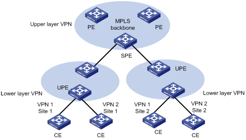
Figure 1-5 Hierarchical MPLS L3VPN
1.1.5 Introduction to OSPF Multi-Instance
As one of the most popular IGP routing protocols, OSPF is used as an internal routing protocol in many VPNs. Using OSPF on PE-CE links brings convenience to you because in this case CE routers only need to support OSPF protocol, without the need of supporting other protocols, and network administrator only have to know the OSPF protocol. If you want to transform conventional OSPF backbone into MPLS L3VPN, using OSPF between PE and CE can simplify this transform process.
Therefore IETF raised two new OSPF VPN extension drafts, to provide a complete solution to SPPF problems in MPLS L3VPN application when OSPF is used as PE-CE routing protocol. In this case, PE router must be able to run multiple OSPF instances, each of which corresponds to one VPN instance, owns an individual interface, routing table, and sends VPN routing information over MPLS network using BGP/OSPF interaction.
If supporting OSPF multi-instance, one router can run multiple OSPF processes, which can be bound to different VPN instances. In practice, you can create one OSPF instance for each service type. OSPF multi-instance can fully isolate different services in transmission, which can solve security problems with low cost to meet the needs of customers. Generally, OSPF multi-instance is run on PEs; The CE running OSPF multi-instance in the LAN is called multi-VPN-instance CE. At present, isolation of LAN services implements by VLAN function of the switch. OSPF Multi-VPN-Instance CE provides schemes of services isolation implemented on routers.
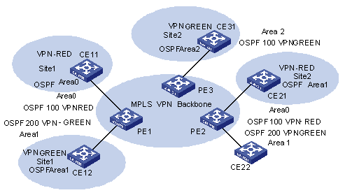
Figure 1-6 OSPF multi-instance application in MPLS L3VPN PE
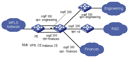
Figure 1-7 Multi-VPN-instance CE application in conventional LAN
1.1.6 Introduction to Multi-Role Host
The VPN attribute of the packets from a CE to its PE lies on the VPN bound with the ingress interface. This, in fact determines that all the CEs forwarded by the PE through the same ingress interface belong to the same VPN; but in actual network environments, a CE may need to access multiple VPNs through one physical interface. Though you can configure different logical interfaces to meet this need, this compromised method brings additional configuration burden and has limitation in actual use.
To resolve this problem, the idea of multi-role host is generated. Specifically to say, this idea is to differentiate the accesses to different VPNs through configuring policy routing based on IP addresses, and transmit downstream data flow from PE to CE by configuring static routing. The static routing under multi-role host circumstance is different from common hosts; it is implemented by specifying an interface of another VPN as the egress interface through a static route in a VPN; and thus allowing one logical interface to access multiple VPNs.
1.2 MPLS L3VPN Configuration
1.2.1 Configuring Various Kinds of Routers
Implementing MPLS L3VPN functions requires the following procedures in general: Configure basic information on PE, CE and P; establish the logical or physical link with IP capabilities from PE to PE; advertise and update VPN network information.
I. CE router
The configuration on CE is relative simple. Only static route, RIP, OSPF or EBGP configuration is needed for VPN routing information exchange with the PE connected, MPLS configuration is not needed.
II. PE router
The configuration on PE is relative complex. After the configuration, the PE implements MPLS L3VPN core functions.
The following sections describe the configuration tasks on a PE device:
l Configuring basic MPLS capability
l Configuring PE-CE route exchanging
l Configuring PE-PE route exchanging
III. P router
The configuration on P device is relative simple. The main task is to configure MPLS basic capacity on the P device to support LDP and MPLS forwarding.
The following are detailed configurations.
1.2.2 Configuring CE Router
As a customer-side device, only basic configuration is required on a CE router, for routing information exchange with PE router. Currently route switching modes available include static route, RIP, OSPF, EBGP, and so on.
I. Creating static route
If you select static route mode for CE-PE route switching, you should then configure a private static route pointing to PE on CE.
Perform the following configuration in the system view to create/delete a static route in VPN instance routing table:
|
To do... |
Use the command... |
|
Create a specified VPN-instance static route |
ip route-static [ vpn-instance vpn-instance-name-list ] ip-address { mask | mask-length } { interface-type interface-number | vpn-instance vpn-instance-name nexthop-ip-address } [ public ] [ preference preference-value | tag tag-value | public ] * [ reject | blackhole ] [ description text ] |
|
Delete a specified VPN-instance static route |
undo ip route-static vpn-instance vpn-instance-name-list destination-ip-address { mask | mask-length } [ interface-name | vpn-instance vpn-nexthop-name ] nexthop-ip-address [ public ] [ preference preference-value ] |
By default, the preference value for a static route is 60. You can also specify preference for a static route.
II. Configuring RIP
If you select RIP mode for CE-PE route switching, you should then configure RIP on CE.
III. Configuring OSPF
If you select OSPF mode for CE-PE route switching, you should then configure OSPF on CE.
You must configure OSPF multi-instance to isolate services of different VPNs on CE router, which is now called Multi-VPN-Instance CE.
You can bind OSPF processes with VPN with the following command in OSPF view.
Table 1-1 Configure the router as multi-VPN-instance CE
|
To do... |
Use the command... |
|
Configure the router as multi-VPN-instance CE |
vpn-instance-capability simple |
|
Remove the configuration |
undo vpn-instance-capability |
IV. Configuring EBGP
If you select BGP mode for CE-PE route switching, you should then configure EBGP peer, import direct-connect route, static route and other IGP routes, for BGP to advertise VPN routes to PE.
1.2.3 Configuring PE Router
I. Configuring basic MPLS capability
It includes configuring MPLS LSR ID, enable MPLS globally and enable MPLS in the corresponding VLAN interface view.
Refer to MPLS Configuration.
II. Defining MPLS L3VPN site
1) Create VPN-instance and enter VPN-instance view
The VPN instance is associated with a site. The VPN membership and routing rules of a site is configured in the corresponding VPN instance.
This command is used to create a new VPN-instance and enter the VPN-instance view, or directly enter the VPN-instance view if the VPN-instance already exists.
Perform the following configuration in the system view to create a VPN-instance and enter VPN-instance view:
|
To do... |
Use the command... |
|
Create a VPN-instance and enter VPN-instance view |
ip vpn-instance vpn-instance-name |
|
Delete a VPN-instance |
undo ip vpn-instance vpn-instance-name |
By default, no VPN-instance is defined.
2) Configure RD for the vpn-instance
After PE router is configured with RD, when a VPN route learned from CE is imported into BGP, BGP attaches the RD in front of the IPv4 address. Then the general IPv4 address which may overlaps between several VPN IPv4 addresses in the VPN is turned into a globally unique VPN IPv4 address and thus ensure the correct routing in the VPN.
Perform the following configuration in VPN-instance view to configure RD for the VPN-instance:
|
To do... |
Use the command... |
|
Configure RD for the VPN-instance |
route-distinguisher route-distinguisher |
The parameter in the above command has no default value. A VPN-instance works only when a RD is configured for it. Other parameters for a VPN-instance cannot be configured before configuring a RD for it.
To modify the RD, you must first delete the VPN-instance and reconfigure it.
3) Configure VPN-instance description
Perform the following configuration in VPN-instance view to configure VPN-instance description:
|
To do... |
Use the command... |
|
Configure VPN-instance description |
description vpn-instance-description |
|
Delete VPN-instance description |
undo description |
4) Configure VPN-target attribute for the VPN-instance
VPN-target attribute, a BGP extension community attribute, controls advertisement of VPN routing information.
The following is the advertisement controlling process of VPN routing information:
l When BGP is imported into a VPN route learned at CE, it associates a VPN-target extension community attribute list for the route. Usually the list is the VPN-instance output routing attribute list which is associated with CE.
l VPN instance defines input routing attribute list according to the import-extcommunity in VPN-target, defines the acceptable route range and import it.
l VPN instance modifies VPN-target attributes for the routes to be advertised, according to the export-extcommunity in VPN-target.
Like an RD, an extension community includes an ASN plus an arbitrary number or an IP address plus an arbitrary number. There are two types of formats:
The first one is related to autonomous system number (ASN), in the form of 16-bit ASN (can be 0 here): 32-bit user-defined number, for example, 100:1.
The second one is related to IP address, in the form of 32-bit IP address (can be 0.0.0.0 here):16-bit user-defined number, for example, 172.1.1.1:1.
Perform the following configuration in the VPN-instance view to create VPN-target extended community for the VPN-instance:
|
To do... |
Use the command... |
|
Configure VPN-target extended community for the VPN-instance |
vpn-target vpn-target-extcommunity [ import-extcommunity | export-extcommunity | both ] |
|
Delete the specified VPN-target attribute from the VPN-target attribute list associated with the VPN-instance |
undo vpn-target vpn-target-extcommunity [ import-extcommunity | export-extcommunity | both ] |
By default, the value is both. In general all Sites in a VPN can be interconnected, and the import-extcommunity and export-extcommunity attributes are the same, so you can execute the command only with the both option.
Up to 16 VPN-targets can be configured with a command, and up to 20 vpn-targets can be configured for a VPN-instance.
5) Limit the maximum number of routes in a VPN-instance
This command is used to limit the maximum number of routes for a VPN-instance so as to avoid too many routes imported from a Site.
Perform the following configuration in the VPN-instance view to set the maximum number of routes in the VPN-instance:
|
To do... |
Use the command... |
|
Limit the maximum number of routes in the VPN-instance |
routing-table limit integer { alarm-integer | syslog-alert } |
|
Remove the maximum number limitation |
undo routing-table limit |
Integer is in the range of 1 to 65536 and alarm-integer is in the range of 1 to 100.
& Note:
Changing the maximum route limit for VPN-instance will not affect the existing routing table. To make the new configuration take effect immediately, you should rebuild the corresponding routing protocol or perform shutdown/undo shutdown operation on the corresponding interface.
6) Configure vlan-id larger than 1024 on the fast Ethernet port of Trunk type (Optional)
Configure vlan-id larger than 1024, with the range of MPLS/VPN VLANs allowed to pass the port from vlan-id to vlan-id + 1023
Perform the following configuration in Ethernet port view to configure the vlan-id range of MPLS/VPN VLANs allowed:
|
To do... |
Use the command... |
|
Configure the vlan-id range of MPLS/VPN VLANs allowed to pass Trunk fast Ethernet ports |
port trunk mpls vlan from vlan-id [ to ] vlanid |
|
Remove the configured vlan-id range of MPLS/VPN VLANs allowed to pass Trunk fast Ethernet ports |
undo port trunk mpls |
By default, the vlan-id range of MPLS/VPN VLANs is from 0 to 1023, and the default value of vlan-id is 0. The value range of vlan-id is from 1 to 3071.
![]() Caution:
Caution:
l This command is only applicable to fast Ethernet ports on the cards with suffix C.
l This command can only be executed on Trunk ports, and MPLS/VPN-enabled VLANs and VLANs out of the configured range are excluded..
l Set the VPN range for the cards and set the range of MPLS/VPN VLAN vlan-id on the interface of the card to 1 to 4094.
Perform the following configuration in system view to configure the MPLS/VPN VLAN vlan-id range for the card:
|
To do... |
Use the command... |
|
Enable the 4K VPN-range for the card |
vlan vpn-range slot slot-number enable |
|
Disable the 4K VPN-range for the card |
undo vlan vpn-range slot slot-number enable |
![]() Caution:
Caution:
l This command is only applicable to fast Ethernet ports on the cards with suffix C.
l This command is actually effective for only the first 12 ports on the card. When you configure MPLS/VPN VLAN vlan-id on subsequent ports, only the MPLS/VPN VLAN range enabled for one VLAN will take effect. If you remove MPLS/VPN configuration from an active port, no subsequent port will take effect automatically either, and you have to reconfigure the ports to update their states.
l For F32GC card, 4 GE ports are initialized for 4k VLANs. Of 32 FE ports, only the first 8 ports will take effect.
l Restart the card after issuing a command or its corresponding undo command to ensure that the configuration takes effect.
l After you cancel card configuration, if the VLAN configured on a port exceeds 1K, which is the default value, the configuration will be deleted automatically.
l In aggregation mode, VPN-range configuration will not be synchronized automatically and you can manually make/remove the configuration on an individual port.
l Set the VPN range for the ports and set the range of MPLS/VPN VLAN vlan-id on the ports to 1 to 4094.
Perform the following configuration in Ethernet interface view.
Table 1-2 Configure the MPLS/VPN VLAN vlan-id range for the interface
|
To do... |
Use the command... |
|
Enable the 4K vpn-range for the interface |
port vpn-range share-mode enable |
|
Disable the 4K vpn-range for the interface |
undo port vpn-range share-mode enable |
![]() Caution:
Caution:
l This command is only applicable to the ports on the cards with suffix C.
l Ports supporting this function stop supporting the application of ACL rules.
7) Associate interface with VPN-instance
VPN instance is associated with the direct-connect Site through interface binding. When the packets from the Site reach the PE router though the interface bound, then the PE can look routing information (including next hop, label, egress interface, and so on.) up in the corresponding VPN-instance.
This command can associate a VPN-instance with an interface.
Perform the following configuration in VLAN interface view to associate interface with VPN-instance:
|
To do... |
Use the command... |
|
Associate interface with VPN-instance |
ip binding vpn-instance vpn-instance-name |
|
Remove the association of the interface with VPN-instance |
undo ip binding vpn-instance vpn-instance-name |
![]() Caution:
Caution:
As executing the ip binding vpn-instance command on an interface will delete the IP address of the interface, you must configure the IP address of the interface after executing that command when you bind the interface with a VPN-instance.
8) Configure an outgoing routing policy for a VPN instance
By configuring an outgoing routing policy for a VPN instance, you can set specific extended community attributes for specific routes.
Perform the following operation in VPN instance view to configure/remove outgoing routing policy association:
|
To do... |
Use the command... |
|
Configure an outgoing routing policy for the VPN instance |
export route-policy route-policy-name |
|
Remove the outgoing routing policy applied on the VPN instance |
undo export route-policy |
III. Configuring PE-CE route exchanging
These route exchanging modes are available between PE and CE: static route, RIP, OSPF, EBGP.
1) Configure static route on PE
You can configure a static route pointing to CE on PE for it to learn VPN routing information from CE.
Perform the following configuration in the system view to create/delete static route in VPN-instance routing table:
|
To do... |
Use the command... |
|
Create the static route of a specific VPN-instance |
ip route-static [ vpn-instance vpn-instance-name-list ] ip-address { mask | mask-length } { interface-type interface-number | vpn-instance vpn-instance-name nexthop-ip-address } [ public ] [ preference preference-value | tag tag-value | public ] * [ reject | blackhole ] [ description text ] |
|
Delete a static route of a specific VPN-instance |
undo ip route-static vpn-instance vpn-instance-name-list destination-ip-address { mask | mask-length } [ interface-name | vpn-instance vpn-nexthop-name ] nexthop-ip-address [ public ] [ preference preference-value ] |
By default, the preference value for a static route is 60. You can also specify another preference for the static route you are configuring.
2) Configure RIP multi-instance
If you select RIP mode for CE-PE route switching, you should then specify running environment for RIP instance on PE. With this command, you can enter RIP view and import and advertise RIP instance in the view.
Perform the following configuration in the RIP view to configure PE-CE RIP instance:
|
To do... |
Use the command... |
|
Create PE-CE RIP instance |
ipv4-family [ unicast ] vpn-instance vpn-instance-name |
|
Delete PE-CE RIP instance |
Then configuring RIP multi-instance to import IBGP route.
3) Configure OSPF multi-instance on PE
If you select OSPF mode for CE-PE route switching, you should then configure OSPF multi-instance on PE. Other configurations, such as MPLS basic configuration, VPN-instance configuration, do not change. Noted that when OSPF routes and direct-connect routes are imported in the VPN instance address family view, BGP routes should also be imported into OSPF. Here only introduces OSPF multi-instance configuration in detail.
First step: Configure OSPF process.
Perform the following configuration in the system view to configure OSPF process:
|
To do... |
Use the command... |
|
Configure an OSPF process |
ospf process-id [ router-id router-id-number ] [ vpn-instance vpn-instance-name ] |
|
Delete an OSPF process |
undo ospf process-id |
By default, the process index is 1.
![]() Caution:
Caution:
An OSPF process can only belong to one VPN instance, while one VPN instance may contain multiple OSPF processes. By default, an OSPF process belongs to public network.
The Domain ID is used to identify an OSPF autonomous system (AS), and the same OSPF domain must have the same Domain ID. One process can be configured with only one Domain ID; different processes can be configured with the same Domain ID or different Domain IDs.
Perform the following configuration in the OSPF view to configure Domain ID:
|
To do... |
Use the command... |
|
Configure Domain ID |
domain-id { id-number | id-addr } |
|
Return to the default value |
undo domain-id |
By default, id-number is 0 and id-addr is 0.0.0.0.
It is recommended that all OSPF instances in a VPN are configured with either the same domain ID or the default value.
![]() Caution:
Caution:
The configured value will not take effect unit the command reset ospf is executed.
Step 3: Configure tag for imported VPN route (optional)
If a VPN Site links to multiple PEs, routing ring may present when the routes learned by MPLS L3VPN are received by another PE router in being advertised by category-5/-7 LSA of a PE to the VPN Site. To solve this problem, you should configure Route-tag. It is recommended to configure identical Route-tag for the PEs in the same VPN.
Perform the following configuration in the OSPF view to Configure tag for imported VPN route:
|
To do... |
Use the command... |
|
Configure tag for imported VPN route |
route-tag tag-number |
|
Return to the default value |
undo route-tag |
![]() Caution:
Caution:
The configured Route-tag will not take effect unit the command reset ospf is executed.
tag-number is used to identify Tag value; by default, the first two bytes are fixed, that is, 0xD000, and the last two bytes is AS number of local BGP. For example, the AS number of local BGP is 100, and then its default tag value is 3489661028 in decimal notation. This value is an integer ranging from 0 to 4294967295.
Step 4: Configure Sham-link (optional)
Sham-links are required between two PEs when Backdoor links (that is, the OSPF links that do not pass through the MPLS backbone network) exist between the two PEs and data is expected to be transported over the MPLS backbone. A Sham-link between two PEs is considered as a link in OSPF domain. Its source and destination addresses are both the Loopback interface address with 32-bit mask, but this Loopback interface should be bound to a VPN instance and direct routes must be imported into BGP by BGP. OSPF processes of the VPN cannot directly import the routes of the Loopback interface (so the import direct command cannot be executed in an OSPF processes of VPN); instead, an OSPF process can only advertise the route indirectly by importing a BGP route.
Perform the following configuration in the OSPF area view to configure Sham-link:
|
To do... |
Use the command... |
|
Configure Sham-link |
sham-link source-addr destination-addr [ cost cost-value ] [ simple password | md5 keyid key ] [ dead seconds ] [ hello seconds ] [ retransimit seconds ] [ trans-delay seconds ] |
|
Delete a Sham-link |
undo sham-link source-addr destination-addr |
By default, the cost value is 1, dead value is 40 seconds, hello value is 10 seconds, retransmit value is 5 seconds and trans-delay value is 1 second.
4) Configure EBGP on PE
If you select EBGP between PE and CE, you should configure a neighbor for each VPN in VPN instance address family sub-view, and import IGP route of CE.
Step 1: Configure peer group
Configuring peer group in VPN instance address family view to configure peer group:
|
To do... |
Use the command... |
|
Configure a peer group |
group group-name [ internal | external ] |
|
Delete the specified peer group |
undo group group-name |
By default, the peer group is configured as internal. When BGP mode is used for PE-CE route switching, they often belong to different ASs, so you should configure EBGP peer as external.
Step 2: Configure AS number for a specific neighbor and add group member to a peer group
When EBGP mode is used for PE-CE route switching, you should configure AS number for a specific neighbor for every CE VPN-instance.
Perform the following configuration in VPN instance address family view to configure AS number for a specific neighbor:
|
To do... |
Use the command... |
|
Configure AS number for a specific neighbor |
peer { group-name | [ peer-address group group-name ] } as-number as-number |
|
Delete the AS number of a specific neighbor |
undo peer { group-name | [peer-address group group-name ] } as-number as-number] |
Step 3: Activate peer (group)
By default, BGP neighbor is active while MBGP neighbor is inactive. You should activate MBGP neighbor in VPNv4 sub-address family view.
Perform the following configuration in VPNv4 sub-address family view to activate/deactivate peer (group):
|
To do... |
Use the command... |
|
Activate the peer (group) |
peer group-name enable |
|
Deactivate the peer (group) |
undo peer group-name enable |
Step 4: Configure MBGP to import VPN route of direct-connect CE
To advertise correct VPN route over public network to other PEs with which BGP adjacency has been created, a PE must import the VPN routing information of the direct-connect CE into its MBGP routing table.
For example, if a static route is used between PE and CE, PE must import a static route in VPN-instance address family sub-view of MBGP (import-route static). If RIP is run between PE and CE, PE must import an RIP route in VPN-instance view of MBGP (import-route rip). If BGP is run between PE and CE, MBGP imports a direct-connect route.
Perform the following configuration in VPN instance address family sub-view to import IGP route:
|
To do... |
Use the command... |
|
Import IGP route |
import-route protocol [ process-id ] [ med med ] |
|
Remove IGP route import |
undo import-route protocol |
Step 5: Configure BGP as asynchronous.
Perform the following configuration in VPN instance address family sub-view to configure BGP asynchronous with IGP:
|
To do... |
Use the command... |
|
Configure BGP asynchronous with IGP |
undo synchronization |
By default, BGP is in asynchronous mode.
Step 6: Permit route loop configuration in Hub&Spoke networking (optional)
Generally speaking, PE-CE configuration is completed after you specify the AS number of neighbor; for the rest configuration, you can keep the system default values.
In the case of standard BGP, BGP tests routing loop via AS number to avoid generating routing loop. In the case of Hub&Spoke networking, however, PE carries the AS number of the local autonomous system when advertising the routing information to CE, if EBGP is run between PE and CE. Accordingly, the updated routing information will carry the AS number of the local autonomous system when route update is received from CE. In this case, PE will not accept the route update information.
This phenomenon can be avoided by executing the peer allow-as-loop command, which makes the PE still receives the route update information containing the local AS number from CE.
Perform the following configuration in IPv4 instance sub-address family view to configure to allow/disable routing loop:
|
To do... |
Use the command... |
|
Configure to allow routing loop |
peer { group-name | peer-address } allow-as-loop asn-limit |
|
Configure to disable routing loop |
undo peer { group-name | peer-address } allow-as-loop asn-limit |
By default, the received route update information is not allowed to generate loop information.
Step 7: Configure BGP features.
IV. Configuring PE-PE route exchanging
To exchange VPN-IPv4 routing information between PEs, you should configure MP-IBGP on PEs.
Perform the following configuration in BGP view or PVN instance address family sub-view.
1) Configure IBGP
These steps are often required.
Step 1: Configure BGP as asynchronous.
Step 2: Configure BGP neighbor.
Note that BGP adjacency is established through Loopback interface and the sub-net mask must be 32 bits.
Step 3: Permit BGP session over any operable TCP interface.
In general, BGP uses the best local address in TCP connection. To keep TCP connection available even when the interface involved fails, you can perform the following configuration to permit BGP session over any interface through which TCP connection with the peer can be set up. The command here is usually executed together with the Loopback interface.
Perform the following configuration in VPNv4 sub-address family view to permit BGP session over any operable TCP interface
|
To do... |
Use the command... |
|
Permit BGP session over any operable TCP interface |
peer { peer-address | group-name } connect-interface { interface-type interface-number } |
|
Use the best local address for TCP connection |
undo peer { peer-address | group-name } connect-interface |
BGP can use a specified interface to establish BGP adjacency with a peer. In MPLS VPN, the interface must be a loopback interface.
2) Configure MP-IBGP
Step 1: Enter protocol address family view.
Perform the following configuration in BGP view to configure VPNv4 address family:
|
To do... |
Use the command... |
|
Enter VPNv4 sub-address family view |
ipv4-family vpnv4 [ unicast ] |
|
Delete VPNv4 sub-address family view configuration |
undo ipv4-family vpnv4 [ unicast ] |
Step 2: Activate the peer (group).
By default, BGP neighbor is active while MBGP neighbor is inactive. You must enable MBGP neighbor in VPNv4 sub-address family view.
Perform the following operation to enable/disable IBGP peer group:
|
To do... |
Use the command... |
|
Enable a peer group |
peer group-name enable |
|
Disable a specific peer group |
undo peer group-name enable |
Step 3: Configure the local address as the next hop in route advertisement (optional).
Since the default value is no configuration, you must show clearly to add in this configuration command when configuring MBGP of PE-PE.
Perform the following configuration in VPNv4 sub-address family view to configure the local address as the next hop in route advertisement:
|
To do... |
Use the command... |
|
Configure the local address as the next hop in route advertisement |
peer { group-name } next-hop-local |
|
Remove the configuration |
undo peer { group-name } next-hop-local |
Step 4: Transfer BGP update packet without AS number (optional)
Perform the following configuration in VPNv4 sub-address family view to transfer BGP update packet without AS number:
|
To do... |
Use the command... |
|
Transfer BGP update packet without AS number |
peer group-name public-as-only |
|
Transfer BGP update packet with AS number |
undo peer group-name public-as-only |
& Note:
In the above-mentioned configuration steps, the public-as-only keyword is required for configuring EBGP and alliance, but not for configuring IBGP.
Step 5: Advertise default route to the peer (group)
This command adds a default route which uses local address as the next hop on the PE SPE (system processing engine)
Perform the following configuration in VPNv4 sub-address family view to advertise default route to the peer (group):
|
To do... |
Use the command... |
|
Advertise default route to the peer (group) |
peer ip-address default-route-advertise vpn-instance vpn-instance name |
|
Remove to advertise default route to the peer (group) |
undo peer ip-address default-route-advertise vpn-instance vpn-instance name |
Step 6: Configure BGP neighbor as the User-end PE (UPE) of MPLS L3VPN
This command is only used for UPE of MPLS L3VPN.
Configure the following commands in the VPNv4 sub-address family view to configure BGP neighbor as the UPE of MPLS L3VPN:
|
To do... |
Use the command... |
|
Configure BGP neighbor as the UPE of MPLS L3VPN |
peer peer-address upe |
|
Disable the configuration |
undo peer peer-address upe |
1.2.4 Configuring P Router
P router does not maintain VPN routes, but do keep connection with public network and coordinate with PE in creating LSPs. These configurations are required on P router:
l Configure MPLS basic capacity and enable LDP on the interfaces connecting P router to PE router, for forwarding MPLS packets. For details, refer to MPLS Configuration.
l Enable OSPF protocol at the interfaces connecting P router to PE router and import direct-connect routes.
1.3 Displaying and Debugging MPLS L3VPN
I. Displaying VPN address information from BGP table
After the above configuration, execute display command in any view to display the running of the VPNv4 information in BGP database configuration, and to verify the effect of the configuration.
Table 1-3 Display VPN address information from BGP table
|
To do... |
Use the command... |
|
Display VPN address information from BGP table |
display bgp vpnv4 { all | route-distinguisher rd-value | vpn-instance vpn-instance-name } { group | network | peer | routing-table } |
II. Displaying IP routing table associated with VPN-instance
After the above configuration, you can execute display command in any view to display the corresponding information in the IP routing tables related to VPN-instance, and to verify the effect of the configuration.
Table 1-4 Display IP routing table associated with VPN-instance
|
To do... |
Use the command... |
|
Display IP routing table associated with VPN-instance |
display ip routing-table vpn-instance vpn-instance-name [ [ip-address ] [ verbose ] | statistics ] |
III. Displaying VPN-instance related information
After the above configuration, executing the display command in any view can display the VPN-instance related information, including its RD, description, the interfaces associated with it, and so on. You can view the information to verify the configuration effect.
Table 1-5 Display VPN-instance related information
|
To do... |
Use the command... |
|
Display the VPN-instance related information, including its RD, description, the interfaces associated with it, and so on |
display ip vpn-instance [ vpn-instance-name | verbose ] |
IV. Debugging information concerning processing BGP
Execute debugging command in user view for the debugging of the related vpn-instance information.
Table 1-6 Enable the debugging for processing BGP
|
To do... |
Use the command... |
|
Enable the debugging for processing BGP |
debugging bgp { all | event | normal | { keepalive | mp-update | open | packet | update | route-refresh | update } [ receive | send |] [ verbose ] } |
|
Disable the debugging |
undo debugging bgp { {all | event | normal | keepalive | mp-update | open | packet | update | route-refresh } [ receive | send | verbose ] } { all | event | normal | update } |
V. Displaying MPLS L3VPN-LSP information
Table 1-7 Display MPLS L3VPN-LSP information
|
To do... |
Use the command... |
|
Display MPLS L3VPN LSP information |
display mpls l3vpn-lsp [ verbose] include text |
|
Display MPLS L3VPN LSP VPN-instance information |
display mpls l3vpn-lsp [ vpn-instance vpn-instance-name ] [ transit | egress | ingress ] [include text | verbose ] |
VI. Displaying Sham-link
|
To do... |
Use the command... |
|
Display Sham-link |
display ospf [ process-id ] sham-link |
1.4 Typical MPLS L3VPN Configuration Examples
1.4.1 Integrated MPLS L3VPN Configuration Example
I. Network requirements
l VPNA includes CE1 and CE3; VPNB includes CE2 and CE4.
l Subscribers in different VPNs cannot access each other. The VPN-target attribute for VPNA is 111:1 and that for VPNB is 222:2.
l The PEs and P are H3C switches supporting MPLS, and CEs are common Layer 3 switches.
& Note:
The configuration in this example is focused on:
l Configure EBGP to exchange VPN routing information between CEs and PEs.
l Configure OSPF for inter-PE communication between PEs.
l Configure MP-IBGP to exchange VPN routing information between PEs.
II. Network diagram
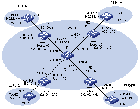
Figure 1-8 Network diagram for integrated MPLS L3VPN
III. Configuration procedure
The following are the configuration introduction to PE, CE and P switches.
1) Configure CE1
# Configure CE1 and PE1 as EBGP neighbors, import direct-connect routes and static routes to import intra-CE1 VPN routes into BGP and advertise to PE1.CE1connects to PE1 through interface GigabitEthernet 2/1/1.
[CE1] vlan 201
[CE1-vlan201] port gigabitethernet 2/1/1
[CE1-vlan201] quit
[CE1] interface Vlan-interface 201
[CE1-Vlan-interface201] ip address 168.1.1.1 255.255.0.0
[CE1-Vlan-interface201] quit
[CE1] bgp 65410
[CE1-bgp] group 168 external
[CE1-bgp] peer 168.1.1.2 group 168 as-number 100
[CE1-bgp] import-route direct
[CE1-bgp] import-route static
& Note:
The configuration on the other three CE switches (CE2 to CE4) is similar to that on CE1, the details are omitted here.
2) Configure PE1
# Configure vpn-instance for VPNA on PE1, as well as other associated attributes to control advertisement of VPN routing information.
[PE1] ip vpn-instance vpna
[PE1-vpn-vpna] route-distinguisher 100:1
[PE1-vpn-vpna] vpn-target 111:1 both
[PE1-vpn-vpna] quit
# Configure PE1 and CE1 as MP-EBGP neighbors, import CE1 VPN routes learned into MBGP VPN-instance address family.
[PE1] bgp 100
[PE1-bgp] ipv4-family vpn-instance vpna
[PE1-bgp-af-vpn-instance] import-route direct
[PE1-bgp-af-vpn-instance] group 168 external
[PE1-bgp-af-vpn-instance] peer 168.1.1.1 group 168 as-number 65410
[PE1-bgp-af- vpn-instance] quit
[PE1-bgp] quit
# Bind the VLAN interface connecting PE1 and CE1 to the VPNA. Note that you should first configure association between the VLAN interface and VPN-instance, and then configure the IP address of the VLAN interface.
[PE1] vlan 202
[PE1-vlan202] port gigabitethernet 2/1/2
[PE1-vlan202] quit
[PE1] interface Vlan-interface 202
[PE1-Vlan-interface202] ip binding vpn-instance vpna
[PE1-Vlan-interface202] ip address 168.1.1.2 255.255.0.0
[PE1-Vlan-interface202] quit
# Configure Loopback interface. (For PE, the IP address for Loopback interface must be a host address with 32-bit mask, to prevent the route is aggregated and then LSP cannot process correctly interior-layer labels.)
[PE1] interface loopback0
[PE1-LoopBack 0] ip address 202.100.1.1 255.255.255.255
[PE1-LoopBack 0] quit
# Configure MPLS basic capacity and enable MPLS and LDP on VLAN interface connecting PE1 and P. Create LSP and achieve MPLS packet forwarding.
[PE1] mpls lsr-id 202.100.1.1
[PE1] mpls
[PE1-mpls] quit
[PE1] mpls ldp
[PE1] vlan 201
[PE1-vlan201] port gigabitethernet 2/1/1
[PE1-vlan201] quit
[PE1] interface Vlan-interface 201
[PE1-Vlan-interface201] ip address 172.1.1.1 255.255.0.0
[PE1-Vlan-interface201] mpls
[PE1-Vlan-interface201] mpls ldp enable
[PE1-Vlan-interface201] quit
# Enable OSPF on the interface connecting PE1 and P and on the Loopback interface, import direct-connect routes. Achieve inter-PE communication.
[PE1] ospf
[PE1-ospf-1] area 0
[PE1-ospf-1-area-0.0.0.0] network 172.1.0.0 0.0.255.255
[PE1-ospf-1-area-0.0.0.0] network 202.100.1.1 0.0.0.0
[PE1-ospf-1-area-0.0.0.0] quit
[PE1-ospf-1] import-route direct
[PE1-ospf-1] quit
# Set up MP-IBGP adjacency between PEs to exchange inter-PE VPN routing information and activate MP-IBGP peer in VPNv4 sub-address family view.
[PE1] bgp 100
[PE1-bgp] group 202 internal
[PE1-bgp] peer 202.100.1.3 group 202
[PE1-bgp] peer 202.100.1.3 connect-interface loopback0
[PE1-bgp] ipv4-family vpnv4
[PE1-bgp-af-vpn] peer 202 enable
[PE1-bgp-af-vpn] peer 202.100.1.3 group 202
[PE1-bgp-af-vpn] quit
[PE1-bgp] quit
3) Configure P
# Configure MPLS basic capacity, enable LDP on the interfaces connecting P and PE for MPLS packet forwarding.
[P] mpls lsr-id 172.1.1.2
[P] mpls
[P-mpls] quit
[P] mpls ldp
[P] interface loopback0
[P-LoopBack 0] ip address 172.1.1.2 255.255.255.255
[P-LoopBack 0] quit
[P] vlan 301
[P-vlan301] port gigabitethernet 3/1/1
[P-vlan301] quit
[P] interface Vlan-interface 301
[P-Vlan-interface301] ip address 172.1.1.2 255.255.0.0
[P-Vlan-interface301] mpls
[P-Vlan-interface301] mpls ldp enable
[P-Vlan-interface301] quit
[P] vlan 302
[P-vlan302] port gigabitethernet 3/1/2
[P-vlan302] quit
[P] interface Vlan-interface 302
[P-Vlan-interface302] ip address 172.2.1.2 255.255.0.0
[P-Vlan-interface302] mpls
[P-Vlan-interface302] mpls ldp enable
[P-Vlan-interface302] quit
[P] vlan 303
[P-vlan303] port gigabitethernet 3/1/3
[P-vlan303] quit
[P] interface Vlan-interface 303
[P-Vlan-interface303] ip address 172.3.1.2 255.255.0.0
[P-Vlan-interface303] mpls
[P-Vlan-interface303] mpls ldp enable
[P-Vlan-interface303] quit
[P] vlan 304
[P-vlan304] port gigabitethernet 3/1/4
[P-vlan304] quit
[P] interface Vlan-interface 304
[P-Vlan-interface304] ip address 172.4.1.2 255.255.0.0
[P-Vlan-interface304] mpls
[P-Vlan-interface304] mpls ldp enable
[P-Vlan-interface304] quit
# Enable OSPF protocol on the interfaces connecting P and PE, import direct-connect route to achieve inter-PE communication.
[P] ospf
[P-ospf-1] area 0
[P-ospf-1-area-0.0.0.0] network 172.1.1.0 0.0.255.255
[P-ospf-1-area-0.0.0.0] network 172.2.1.0 0.0.255.255
[P-ospf-1-area-0.0.0.0] network 172.3.1.0 0.0.255.255
[P-ospf-1-area-0.0.0.0] network 172.4.1.0 0.0.255.255
[P-ospf-1-area-0.0.0.0] quit
[P-ospf-1] import-route direct
4) Configure PE3
& Note:
The configuration on PE3 is similar to that on PE1, you should pay more attention to VPN routing attribute setting on PE3 to get information about how to control advertisement of a same VPN routing information (with same VPN-target) over MPLS network.
# Create VPN-instance for VPNA on PE3, configure correlative attributes to control advertisement of VPN routing information.
[PE3] ip vpn-instance vpna
[PE3-vpn-vpna] route-distinguisher 100:3
[PE3-vpn-vpna] vpn-target 111:1 both
[PE3-vpn-vpna] quit
# Set up MP-EBGP adjacency between PE3 and CE3, import intra-CE3 VPN routes learned into MBGP VPN-instance address family.
[PE3] bgp 100
[PE3-bgp] ipv4-family vpn-instance vpna
[PE3-bgp-af-vpn-instance] import-route direct
[PE3-bgp-af-vpn-instance] group 168 external
[PE3-bgp-af-vpn-instance] peer 168.3.1.1 group 168 as-number 65430
[PE3-bgp-af-vpn-instance] quit
[PE3-bgp] quit
# Bind the interface connecting PE3 and CE3 to VPNA.
[PE3] vlan 202
[PE3-vlan202] port gigabitethernet 2/1/2
[PE3-vlan202] quit
[PE3] interface Vlan-interface 202
[PE3-Vlan-interface202] ip binding vpn-instance vpna
[PE3-Vlan-interface202] ip address 168.3.1.2 255.255.0.0
[PE3-Vlan-interface202] quit
# Configure Loopback interface
[PE3] interface loopback0
[PE3-LoopBack 0] ip address 202.100.1.3 255.255.255.255
[PE3-LoopBack 0] quit
# Configure MPLS basic capacity and enable MPLS and LDP on VLAN interface connecting PE3 and P. Creates LSP and achieve MPLS packet forwarding.
[PE3] mpls lsr-id 202.100.1.3
[PE3] mpls
[PE3-mpls] quit
[PE3] mpls ldp
[PE3] vlan 201
[PE3-vlan201] interface gigabitethernet 2/1/1
[PE3-vlan201] quit
[PE3] interface Vlan-interface 201
[PE3-Vlan-interface201] ip address 172.3.1.1 255.255.0.0
[PE3-Vlan-interface201] mpls
[PE3-Vlan-interface201] mpls ldp enable
[PE3-Vlan-interface201] quit
# Enable OSPF on the interface connecting PE3 and P and the Loopback interface, import direct-connect routes.
[PE3] ospf
[PE3-ospf-1] area 0
[PE3-ospf-1-area-0.0.0.0] network 172.3.0.0 0.0.255.255
[PE3-ospf-1-area-0.0.0.0] network 202.100.1.3 0.0.0.0
PE3-ospf-1-area-0.0.0.0] quit
[PE3-ospf-1] import-route direct
[PE3-ospf-1-area-0.0.0.0] import-route direct
# Set up MP-IBGP adjacency between PEs to exchange inter-PE VPN routing information.
[PE3] bgp 100
[PE3-bgp] group 202 internal
[PE3-bgp] peer 202.100.1.1 group 202 as-number 100
[PE3-bgp] peer 202.100.1.1 connect-interface loopback0
[PE3-bgp] ipv4-family vpnv4
[PE3-bgp-af-vpn] peer 202 enable
[PE3-bgp-af-vpn] peer 202.100.1.1 group 202
[PE3-bgp-af-vpn] quit
5) Configure PE2 and PE4
The configuration of PE2 and PE4 is similar to that of PE1 and PE3. The details are omitted here.
1.4.2 Extranet Configuration Example
I. Network requirements
Company A and Company B are located at City A and City B respectively. Their headquarters is located at City C. They respectively own VPN1 and VPN2.
In this example, VPN function is provided by MPLS. There are some shared resources at the City C for the two VPNs. All subscribers in both VPNs can access the shared resources, but VPN subscribers in City A and City B cannot access each other.
The two companies cannot use identical IP addresses, for they share the same VPN-instance at PE-C.
& Note:
In the example the configuration is focused on controlling access authority of VPN subscribers at different cities by configuring different VPN-target attributes at different PEs.
II. Network diagram
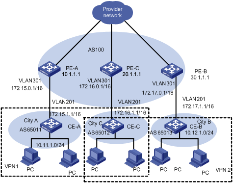
Figure 1-9 Network diagram for Extranet
III. Configuration procedure
& Note:
This configuration procedure has omitted configurations between PE and P, and configurations on CEs. For these details refer to the former example.
1) Configure PE-A:
# Configure VPN-instance 1 for VPN1 on PE-A, so that it can send and receive VPN routing information of VPN-target 111:1.
[PE-A] ip vpn-instance vpn-instance 1
[PE-A-vpn-1] route-distinguisher 100:1
[PE-A-vpn-1] vpn-target 111:1 both
[PE-A-vpn-1] quit
# Set up MP-EBGP adjacency between PE-A and CE-A, import intra-CE-A VPN routes learned into MBGP VPN-instance address family.
[PE-A] bgp 100
[PE-A-bgp] ipv4-family vpn-instance vpn-instance1
[PE-A-bgp-af-vpn-instance] import-route direct
[PE-A-bgp-af-vpn-instance] import-route static
[PE-A-bgp-af-vpn-instance] group 172 external
[PE-A-bgp-af-vpn-instance] peer 172.15.1.1 group 172 as-number 65011
[PE-A-bgp-af-vpn-instance] quit
[PE-A-bgp] quit
# Bind VPN-instance1 with the interface of VLAN 301 which connects CE-A.
[PE-A] vlan 301
[PE-A-vlan301] port gigabitethernet 3/1/1
[PE-A-vlan301] quit
[PE-A] interface Vlan-interface 301
[PE-A-Vlan-interface301] ip binding vpn-instance vpn-instance1
[PE-A-Vlan-interface301] ip address 172.15.0.1 255.255.0.0
[PE-A-Vlan-interface301] quit
# Configure Loopback interface
[PE-A] interface loopback 0
[PE-A-LoopBack0] ip address 10.1.1.1 255.255.255.255
[PE-A-LoopBack0] quit
# Configure MPLS basic capacity.
[PE-A] mpls lsr-id 10.1.1.1
[PE-A] mpls
[PE-A-mpls] quit
[PE-A] mpls ldp
# Set up MP-IBGP adjacency between PEs to exchange inter-PE VPN routing information and activate MP-IBGP peer in VPNv4 sub-address family view.
[PE-A] bgp 100
[PE-A-bgp] group 20 internal
[PE-A-bgp] peer 20.1.1.1 group 20
[PE-A-bgp] peer 20.1.1.1 connect-interface loopback 0
[PE-A-bgp] ipv4-family vpnv4
[PE-A-bgp-af-vpn] peer 20 enable
[PE-A-bgp-af-vpn] peer 20.1.1.1 group 20
[PE-A-bgp-af-vpn] quit
2) Configure PE-C.
# Create a VPN-instance 2 on PE-C, so that it can send and receive VPN routing information of VPN-target 111:1 and 222:2.
[PE-C] ip vpn-instance vpn-instance 2
[PE-C-vpn-2] route-distinguisher 100:2
[PE-C-vpn-2] vpn-target 111:1 both
[PE-C-vpn-2] vpn-target 222:2 both
[PE-C-vpn-2] quit
# Set up MP-EBGP adjacency between PE-C and CE-C, import intra-CE-C VPN routes learned into MBGP VPN-instance address family.
[PE-C] bgp 100
[PE-C-bgp] ipv4-family vpn-instance vpn-instance2
[PE-C-bgp-af-vpn-instance] import-route direct
[PE-C-bgp-af-vpn-instance] import-route static
[PE-C-bgp-af-vpn-instance] group 172 external
[PE-C-bgp-af-vpn-instance] peer 172.16.1.1 group 172 as-number 65012
[PE-C-bgp-af-vpn-instance] quit
[PE-C-bgp] quit
# Bind VPN-instance2 with the interface of VLAN301 which connects CE-C.
[PE-C] vlan 301
[PE-C-vlan301] port gigabitethernet 3/1/1
[PE-C-vlan301] quit
[PE-C] interface Vlan-interface 301
[PE-C-Vlan-interface301] ip binding vpn-instance vpn-instance2
[PE-C-Vlan-interface301] ip address 172.16.0.1 255.255.0.0
[PE-C-Vlan-interface301] quit
# Configure Loopback interface
[PE-C] interface loopback 0
[PE-C-LoopBack0] ip address 20.1.1.1 255.255.255.255
[PE-C-LoopBack0] quit
# Configure MPLS basic capacity.
[PE-C] mpls lsr-id 20.1.1.1
[PE-C] mpls
[PE-C-mpls] quit
[PE-C] mpls ldp
# Set up MP-IBGP adjacency between PEs to exchange inter-PE VPN routing information and activate MP-IBGP peer in VPNv4 sub-address family view.
[PE-C] bgp 100
[PE-C-bgp] group 10
[PE-C-bgp] peer 10.1.1.1 group 10
[PE-C-bgp] peer 10.1.1.1 connect-interface loopback 0
[PE-C-bgp] group 30
[PE-C-bgp] peer 30.1.1.1 group 30
[PE-C-bgp] peer 30.1.1.1 connect-interface loopback 0
[PE-C-bgp] ipv4-family vpnv4
[PE-C-bgp-af-vpn] peer 10 enable
[PE-C-bgp-af-vpn] peer 10.1.1.1 group 10
[PE-C-bgp-af-vpn] peer 30 enable
[PE-C-bgp-af-vpn] peer 30.1.1.1 group 30
[PE-C-bgp-af-vpn] quit
3) Configure PE-B:
# Create VPN-instance 3 for VPN2 on PE-B, so that it can send and receive VPN routing information of VPN-target 222:2.
[PE-B] ip vpn-instance vpn-instance 3
[PE-B-vpn-3] route-distinguisher 100:3
[PE-B-vpn-3] vpn-target 222:2 both
[PE-B-vpn-3] quit
# Set up MP-EBGP adjacency between PE-B and CE-B, import intra-CE-B VPN routes learned into MBGP VPN-instance address family.
[PE-B] bgp 100
[PE-B-bgp] ipv4-family vpn-instance vpn-instance3
[PE-B-bgp-af-vpn-instance] import-route direct
[PE-B-bgp-af-vpn-instance] import-route static
[PE-B-bgp-af-vpn-instance] group 172 external
[PE-B-bgp-af-vpn-instance] peer 172.17.1.1 group 172 as-number 65013
[PE-B-bgp-af-vpn-instance] quit
[PE-B-bgp] quit
# Bind VPN-instance3 with the interface of VLAN301 which connects to CE-B.
[PE-B] vlan 301
[PE-B-vlan301] port gigabitethernet 3/1/1
[PE-B-vlan301] quit
[PE-B] interface Vlan-interface 301
[PE-B-Vlan-interface301] ip binding vpn-instance vpn-instance3
[PE-B-Vlan-interface301] ip address 172.17.0.1 255.255.0.0
[PE-B-Vlan-interface301] quit
# Configure Loopback interface
[PE-B] interface loopback 0
[PE-B-LoopBack0] ip address 30.1.1.1 255.255.255.255
[PE-B-LoopBack0] quit
# Configure MPLS basic capacity.
[PE-B] mpls lsr-id 30.1.1.1
[PE-B] mpls
[PE-B-mpls] quit
[PE-B] mpls ldp
# Set up MP-IBGP adjacency between PEs to exchange inter-PE VPN routing information and activate MP-IBGP peer in VPNv4 sub-address family view.
[PE-B] bgp 100
[PE-B-bgp] group 20
[PE-B-bgp] peer 20.1.1.1 group 20
[PE-B-bgp] peer 20.1.1.1 connect-interface loopback 0
[PE-B-bgp] ipv4-family vpnv4
[PE-B-bgp-af-vpn] peer 20 enable
[PE-B-bgp-af-vpn] peer 20.1.1.1 group 20
[PE-B-bgp-af-vpn] quit
1.4.3 Hub&Spoke Configuration Example
I. Network requirements
Hub&Spoke networking is also called central server networking. The Site in the center is called Hub-Site, while the one not in the center is called Spoke-Site. The Hub-Site knows the routes to all other Sites in the same VPN, and the Spoke-Site must send its traffic first to the Hub-Site and then to the destination. Hub-Site is the central node of Spoke-Sites.
A bank has a headquarters network and subsidiary networks, and it requires that the subsidiaries cannot directly exchange data with each other, but they can exchange data through the headquarters network which provides uniform control. In this example, Hub&Spoke networking topology is used: CE2 and CE3 are spoke-sites, while CE1 is a hub-site in the bank data center. CE1 controls communication between CE2 and CE3.
l Set up IBGP adjacency between PE1 and PE2 or PE1 and PE3, but not between PE2 and PE3, that is, VPN routing information cannot be exchanged between PE2 and PE3.
l Create two VPN-instances on PE1, import VPN routes of VPN-target 100:11 and 100:12, set VPN-target for VPN routes advertised as 100:2.
l Create a VPN-instance on PE2, import VPN routes of VPN-target 100:2, set VPN-target for VPN routes advertised as 100:11.
l Create a VPN-instance on PE3, import VPN routes of VPN-target 100:2, set VPN-target for VPN routes advertised as 100:12.
Then PE2 and PE3 can only learn their neighbor’s routes through PE1.
& Note:
In this example the configuration is focused on four points:
l Route advertisement can be controlled by VPN-target settings on different PEs.
l Routing loop is permitted only once, so that PE can receive route update messages with AS number included from CE.
l In Hub&Spoke networking, VPN-target of VPN-instance (VPN-instance3) which is used to release route on the PE1 cannot be the same with any VPN-target of VPN-instance (VPN-instance2) which is used to import route on PE1.
l In Hub&Spoke networking, route-distinguisher rd2 (100:3) of VPN-instance which is used to release route on the PE1 cannot be the same with the route-distinguisher rd1 (100:1) or rd4 (100:4) of corresponding VPN-instances on each PE2 and PE3; rd 1 and rd4 can be the same or not.
II. Network diagram
Figure 1-10 Network diagram for Hub&Spoke
III. Configuration procedure
& Note:
The following contents are omitted in this example: MPLS basic capacity configuration between PEs, configuration between PE and P, configuration between CEs. For details refer to Integrated MPLS L3VPN Configuration Example.
1) Configure PE1
# Configure two VPN-instances on PE1, set specified VPN-target for the routes received from PE2 and PE3.
[PE1] ip vpn-instance vpn-instance2
[PE1-vpn-vpn-instance2] route-distinguisher 100:2
[PE1-vpn-vpn-instance2] vpn-target 100:11 import-extcommunity
[PE1-vpn-vpn-instance2] vpn-target 100:12 import-extcommunity
[PE1-vpn-instance2] quit
[PE1] ip vpn-instance vpn-instance3
[PE1-vpn-vpn-instance3] route-distinguisher 100:3
[PE1-vpn-vpn-instance3] vpn-target 100:2 export-extcommunity
[PE1-vpn-vpn-instance3] quit
# Set up EBGP adjacency between PE1 and CE1, import intra-CE1 VPN routes learned into MBGP VPN-instance address family, with one routing loop permitted.
[PE1] bgp 100
[PE1-bgp] ipv4-family vpn-instance vpn-instance2
[PE1-bgp-af-vpn-instance] import-route static
[PE1-bgp-af-vpn-instance] import-route direct
[PE1-bgp-af-vpn-instance] group 17216 external
[PE1-bgp-af-vpn-instance] peer 172.16.1.1 group 17216 as-number 65002
[PE1-bgp-af-vpn-instance] quit
[PE1-bgp] ipv4-family vpn-instance vpn-instance3
[PE1-bgp-af-vpn-instance] import-route static
[PE1-bgp-af-vpn-instance] import-route direct
[PE1-bgp-af-vpn-instance] group 17217 external
[PE1-bgp-af-vpn-instance] peer 172.17.1.1 group 17217 as-number 65002
[PE1-bgp-af-vpn-instance] peer 172.17.1.1 allow-as-loop 1
[PE1-bgp-af-vpn] quit
[PE1-bgp] quit
# Bind the VLAN interface connecting PE1 and CE1 to different VPN-instances. Bind the interface of the VLAN to which the Ethernet port Gigabitethernet 2/1/1 belongs to VPN-instance2, bind the interface of the VLAN to which the Ethernet port Gigabitethernet 2/1/2 belongs to VPN-instance3.
[PE1] vlan 201
[PE1-vlan201] port gigabitethernet 2/1/1
[PE1-vlan201] quit
[PE1] interface Vlan-interface 201
[PE1-Vlan-interface201] ip binding vpn-instance vpn-instance2
[PE1-Vlan-interface201] ip address 172.16.0.1 255.255.0.0
[PE1-Vlan-interface201] quit
[PE1] vlan 202
[PE1-vlan202] port gigabitethernet 2/1/2
[PE1-vlan202] quit
[PE1] interface Vlan-interface 202
[PE1-Vlan-interface202] ip binding vpn-instance vpn-instance3
[PE1-Vlan-interface202] ip address 172.17.0.1 255.255.0.0
[PE1-Vlan-interface202] quit
# Configure Loopback interface
[PE1] interface loopback 0
[PE1-LoopBack0] ip address 11.1.1.1 255.255.255.255
[PE1-LoopBack0] quit
# Set up MP-IBGP adjacency between PEs to exchange inter-PE VPN routing information and activate MP-IBGP peer in VPNv4 sub-address family view.
[PE1] bgp 100
[PE1-bgp] group 22
[PE1-bgp] peer 22.1.1.1 group 22 as-number 100
[PE1-bgp] peer 22.1.1.1 connect-interface loopback 0
[PE1-bgp] group 33
[PE1-bgp] peer 33.1.1.1 group 33 as-number 100
[PE1-bgp] peer 33.1.1.1 connect-interface loopback 0
[PE1-bgp] ipv4-family vpnv4
[PE1-bgp-af-vpn] peer 22 enable
[PE1-bgp-af-vpn] peer 22.1.1.1 group 22
[PE1-bgp-af-vpn] peer 33 enable
[PE1-bgp-af-vpn] peer 33.1.1.1 group 33
[PE1-bgp-af-vpn] quit
2) Configure PE2
# Create a VPN-instance on PE2, import VPN routing information of VPN-target 100:2 and advertise VPN routing information of VPN-target 100:1.
[PE2] ip vpn-instance vpn-instance1
[PE2-vpn-vpn-instance1] route-distinguisher 100:1
[PE2-vpn-vpn-instance1] vpn-target 100:11 export-extcommunity
[PE2-vpn-vpn-instance1] vpn-target 100:2 import-extcommunity
[PE2-vpn-vpn-instance1] quit
# Set up EBGP adjacency between PE2 and CE2, import intra-CE2 VPN routes learned into MBGP VPN-instance address family.
[PE2] bgp 100
[PE2-bgp] ipv4-family vpn-instance vpn-instance1
[PE2-bgp-af-vpn-instance] import-route static
[PE2-bgp-af-vpn-instance] import-route direct
[PE2-bgp-af-vpn-instance] group 172 external
[PE2-bgp-af-vpn-instance] peer 172.15.1.1 group 172 as-number 65003
[PE2-bgp-af-vpn-instance] quit
[PE2-bgp] quit
# Bind the interface of the VLAN to which the port connecting PE2 and CE2 belongs to VPN-instance.
[PE2] vlan 201
[PE2-vlan201] port gigabitethernet 2/1/1
[PE2-vlan201] quit
[PE2] interface Vlan-interface 201
[PE2-Vlan-interface201] ip binding vpn-instance vpn-instance1
[PE2-Vlan-interface201] ip address 172.15.0.1 255.255.0.0
[PE2-Vlan-interface201] quit
# Configure Loopback interface
[PE2] interface loopback 0
[PE2-LoopBack0] ip address 22.1.1.1 255.255.255.255
[PE2-LoopBack0] quit
# Set up MP-IBGP adjacency between PE2 and PE1 to exchange inter-PE VPN routing information and activate MP-IBGP peer in VPNv4 sub-address family view.
[PE2] bgp 100
[PE2] group 11
[PE2-bgp] peer 11.1.1.1 group 11 as-number 100
[PE2-bgp] peer 11.1.1.1 connect-interface loopback 0
[PE2-bgp] ipv4-family vpnv4
[PE2-bgp-af-vpn] peer 11 enable
[PE2-bgp-af-vpn] peer 11.1.1.1 allow-as-loop 1
[PE2-bgp-af-vpn] quit
[PE2-bgp] quit
3) Configure PE3
# Create a VPN-instance on PE3, import VPN routing information of VPN-target 100:2 and advertise VPN routing information of VPN-target 100:12.
[PE3] ip vpn-instance vpn-instance2
[PE3-vpn-vpn-instance2] route-distinguisher 100:4
[PE3-vpn-vpn-instance2] vpn-target 100:12 export-extcommunity
[PE3-vpn-vpn-instance2] vpn-target 100:2 import-extcommunity
[PE3-vpn-vpn-instance2] quit
# Set up EBGP adjacency between PE3 and CE3 import intra-CE3 VPN routes learned into MBGP VPN-instance address family.
[PE3] bgp 100
[PE3-bgp] ipv4-family vpn-instance vpn-instance2
[PE3-bgp-af-vpn-instance] import-route static
[PE3-bgp-af-vpn-instance] import-route direct
[PE3-bgp-af-vpn-instance] group 172 external
[PE3-bgp-af-vpn-instance] peer 172.18.1.1 group 172 as-number 65001
[PE3-bgp-af-vpn-instance] quit
[PE3-bgp] quit
# Bind the interface of the VLAN to which the port connecting PE3 and CE3 belongs to VPN-instance.
[PE3] vlan 201
[PE3-vlan201] port gigabitethernet 2/1/1
[PE3-vlan201] quit
[PE3] interface Vlan-interface 201
[PE3-Vlan-interface201] ip binding vpn-instance vpn-instance2
[PE3-Vlan-interface201] ip address 172.18.0.1 255.255.0.0
[PE3-Vlan-interface201] quit
# Configure Loopback interface
[PE3] interface loopback 0
[PE3-LoopBack0] ip address 33.1.1.1 255.255.255.255
[PE3-LoopBack0] quit
# Set up MP-IBGP adjacency between PE3 and PE1 to exchange inter-PE VPN routing information and activate MP-IBGP peer in VPNv4 sub-address family view.
[PE3] bgp 100
[PE3-bgp] group 11
[PE3-bgp] peer 11.1.1.1 group 11
[PE3-bgp] peer 11.1.1.1 connect-interface loopback 0
[PE3-bgp] ipv4-family vpnv4
[PE3-bgp-af-vpn] peer 11 enable
[PE2-bgp-af-vpn] peer 11.1.1.1 group 11
[PE2-bgp-af-vpn] peer 11.1.1.1 allow-as-loop 1
[PE3-bgp-af-vpn] quit
[PE3-bgp] quit
1.4.4 CE Dual-home Configuration Example
I. Network requirements
For the applications which require high robustness of network, you may use CE dual-home networking mode.
CE1 and CE2 are dual-homed; they are connected to both PE1 and PE2. Three PEs are connected to each other so the links between them are backed up. CE3 and CE4 are single-homed; each of them is only connected to one PE.
CE1 and CE3 are in one VPN, and CE2 and CE4 are in another VPN. The two VPNs cannot intercommunicate with each other.
II. Network diagram
Figure 1-11 Network diagram for CE dual-home
III. Configuration procedure
& Note:
The configuration of CE router is omitted in this example and you can refer to Integrated MPLS L3VPN Configuration Example.
1) Configure PE1
# Configure two VPN-instances 1.1 and 1.2 respectively for CE1 and CE2 on PE1, set different VPN-targets for them.
[PE1] ip vpn-instance vpn-instance1.1
[PE1-vpn-vpn-instance1.1] route-distinguisher 1.1.1.1:1
[PE1-vpn-vpn-instance1.1] vpn-target 1.1.1.1:1
[PE1-vpn-vpn-instance1.1] quit
[PE1] ip vpn-instance vpn-instance1.2
[PE1-vpn-vpn-instance1.2] route-distinguisher 2.2.2.2:2
[PE1-vpn-vpn-instance1.2] vpn-target 2.2.2.2:2
[PE1-vpn-vpn-instance1.2] quit
# Set up EBGP adjacency between PE1 and CE1 in VPN-instance 1, import intra-CE1 VPN routes learned into VPN-instance 1.1.
[PE1] bgp 100
[PE1-bgp] ipv4-family vpn-instance vpn-instance1.1
[PE1-bgp-af-vpn-instance] import-route direct
[PE1-bgp-af-vpn-instance] import-route static
[PE1-bgp-af-vpn-instance] group 17211 external
[PE1-bgp-af-vpn-instance] peer 172.11.11.2 group 17211 as-number 65001
[PE1-bgp-af-vpn-instance] quit
[PE1-bgp] quit
# Set up EBGP adjacency between PE1 and CE2 in VPN-instance 1.2, import intra-CE2 VPN routes learned into VPN-instance 1.2.
[PE1-bgp] ipv4-family vpn-instance vpn-instance1.2
[PE1-bgp-af-vpn-instance] import-route direct
[PE1-bgp-af-vpn-instance] import-route static
[PE1-bgp-af-vpn-instance] group 17221 external
[PE1-bgp-af-vpn-instance] peer 172.21.21.2 group 17221 as-number 65002
[PE1-bgp-af-vpn] quit
[PE1-bgp] quit
# Bind the interface connecting PE1 and CE1 to VPN-instance 1.1 and interface connecting PE1 and CE2 to VPN-instance 1.2.
[PE1] vlan 211
[PE1-vlan211] port gigabitethernet 2/1/1
[PE1-vlan211] quit
[PE1] interface Vlan-interface 211
[PE1-Vlan-interface211] ip binding vpn-instance vpn-instance1.1
[PE1-Vlan-interface211] ip address 172.11.11.1 255.255.255.0
[PE1-Vlan-interface211] quit
[PE1] vlan 212
[PE1-vlan212] port gigabitethernet 2/1/2
[PE1-vlan212] quit
[PE1] interface Vlan-interface 212
[PE1-Vlan-interface212] ip binding vpn-instance vpn-instance1.2
[PE1-Vlan-interface212] ip address 172.21.21.1 255.255.255.0
[PE1-Vlan-interface212] quit
# Configure Loopback interface
[PE1] interface loopback 0
[PE1-LoopBack0] ip address 1.1.1.1 255.255.255.255
[PE1-LoopBack0] quit
# Configure MPLS basic capacity, enable LDP on the interface connecting PE1 and PE2 and the interface connecting PE1 and PE3.
[PE1] mpls lsr-id 1.1.1.1
[PE1] mpls
[PE1-mpls] quit
[PE1] mpls ldp
[PE1] vlan 213
[PE1-vlan213] port gigabitethernet 2/1/3
[PE1-vlan213] quit
[PE1] interface Vlan-interface213
[PE1-Vlan-interface213] mpls
[PE1-Vlan-interface213] mpls ldp enable
[PE1-Vlan-interface213] mpls ldp transport-ip interface
[PE1-Vlan-interface213] ip address 10.1.1.1 255.255.255.0
[PE1-Vlan-interface213] quit
[PE1] vlan 214
[PE1-vlan214] port gigabitethernet 2/1/4
[PE1-vlan214] quit
[PE1] interface Vlan-interface 214
[PE1-Vlan-interface214] mpls
[PE1-Vlan-interface214] mpls ldp enable
[PE1-Vlan-interface214] mpls ldp transport-ip interface
[PE1-Vlan-interface214] ip address 30.1.1.2 255.255.255.0
[PE1-Vlan-interface214] quit
# Enable OSPF on the interface connecting PE1 and PE2 and the interface connecting PE1 and PE3 and the Loopback interface, to achieve inter-PE communication.
[PE1] Router-id 1.1.1.1
[PE1] ospf
[PE1-ospf-1] area 0
[PE1-ospf-1-area-0.0.0.0] network 1.1.1.1 0.0.0.0
[PE1-ospf-1-area-0.0.0.0] network 30.1.1.2 0.0.0.255
[PE1-ospf-1-area-0.0.0.0] network 10.1.1.1 0.0.0.255
[PE1-ospf-1-area-0.0.0.0] quit
[PE1-ospf-1] quit
# Set up MP-IBGP adjacency between PEs to exchange inter-PE VPN routing information and activate MP-IBGP peer in VPNv4 sub-address family view.
[PE1] bgp 100
[PE1-bgp] group 2
[PE1-bgp] peer 2.2.2.2 group 2
[PE1-bgp] peer 2.2.2.2 connect-interface loopback 0
[PE1-bgp] group 3
[PE1-bgp] peer 3.3.3.3 group 3
[PE1-bgp] peer 3.3.3.3 connect-interface loopback 0
[PE1-bgp] ipv4-family vpnv4
[PE1-bgp-af-vpn] peer 2 enable
[PE1-bgp-af-vpn] peer 2.2.2.2 group 2
[PE1-bgp-af-vpn] peer 3 enable
[PE1-bgp-af-vpn] peer 3.3.3.3 group 3
[PE1-bgp-af-vpn] quit
2) Configure PE2
& Note:
The configuration of PE2 is similar to that of PE1, so only VPN-instance configuration is detailed here.
# Create two VPN-instances 2.1 and 2.2 respectively for CE1 and CE2 on PE2, configure different VPN-targets for them.
[PE2] ip vpn-instance vpn-instance2.1
[PE2-vpn-vpn-instance2.1] route-distinguisher 1.1.1.1:1
[PE2-vpn-vpn-instance2.1] vpn-target 1.1.1.1:1
[PE2-vpn-vpn-instance2.1] quit
[PE2] ip vpn-instance vpn-instance2.2
[PE2-vpn-vpn-instance2.2] route-distinguisher 2.2.2.2:2
[PE2-vpn-vpn-instance2.2] vpn-target 2.2.2.2:2
[PE2-vpn-vpn-instance2.2] quit
# Set up EBGP adjacency between PE2 and CE1 in VPN-instance 2.1, import intra-CE1 VPN routes learned into VPN-instance2.1.
[PE2] bgp 100
[PE2-bgp] ipv4-family vpn-instance vpn-instance2.1
[PE2-bgp-af-vpn-instance] import-route direct
[PE2-bgp-af-vpn-instance] import-route static
[PE2-bgp-af-vpn-instance] group 17212 external
[PE2-bgp-af-vpn-instance] peer 172.12.12.2 group 17212 as-number 65001
[PE2-bgp-af-vpn] quit
# Set up EBGP adjacency between PE2 and CE2 in VPN-instance2.2, import intra-CE2 VPN routes learned into VPN-instance2.2.
[PE2-bgp] ipv4-family vpn-instance vpn-instance2.2
[PE2-bgp-af-vpn-instance] import-route direct
[PE2-bgp-af-vpn-instance] import-route static
[PE2-bgp-af-vpn-instance] group 17222 external
[PE2-bgp-af-vpn-instance] peer 172.22.22.2 group 17222 as-number 65002
[PE2-bgp-af-vpn] quit
[PE2-bgp] quit
# Bind the interface connecting PE2 and CE1 to VPN-instance 2.1 and the interface connecting PE2 and CE2 to VPN-instance 2.2.
[PE2] vlan 212
[PE2-vlan212] port gigabitethernet 2/1/2
[PE2-vlan212] quit
[PE2] interface Vlan-interface 212
[PE2-Vlan-interface212] ip binding vpn-instance vpn-instance2.1
[PE2-Vlan-interface212] ip address 172.12.12.1 255.255.255.0
[PE2-Vlan-interface212] quit
[PE2] vlan 211
[PE2-vlan211] port gigabitethernet 2/1/1
[PE2-vlan211] quit
[PE2] interface Vlan-interface 211
[PE2-Vlan-interface211] ip binding vpn-instance vpn-instance2.2
[PE2-Vlan-interface211] ip address 172.22.22.1 255.255.255.0
[PE2-Vlan-interface211] quit
3) Configure PE3
& Note:
Only the VPN-instance configuration of PE3 is detailed here, other configurations are similar to that of the PE1 and PE2, and are omitted here.
# Create two VPN-instances 3.1 and 3.2 respectively for CE3 and CE4 on PE3, configure different VPN-targets for them.
[PE3] ip vpn-instance vpn-instance3.1
[PE3-vpn-vpn-instance3.1] route-distinguisher 1.1.1.1:1
[PE3-vpn-vpn-instance3.1] vpn-target 1.1.1.1:1
[PE3-vpn-vpn-instance3.1] quit
[PE3] ip vpn-instance vpn-instance3.2
[PE3-vpn-instance] route-distinguisher 2.2.2.2:2
[PE3-vpn-instance] vpn-target 2.2.2.2:2
[PE3-vpn-instance] quit
# Set up EBGP adjacency between PE3 and CE3 in VPN-instance3.1, import intra-CE3 VPN routes learned into VPN-instance3.1.
[PE3] bgp 100
[PE3-bgp] ipv4-family vpn-instance vpn-instance3.1
[PE3-bgp-af-vpn-instance] import-route direct
[PE3-bgp-af-vpn-instance] import-route static
[PE3-bgp-af-vpn-instance] group 192 external
[PE3-bgp-af-vpn-instance] peer 192.168.13.2 group 192 as-number 65003
[PE3-bgp-af-vpn-instance] quit
[PE3-bgp] quit
# Set up EBGP adjacency between PE3 and CE4 in VPN-instance3.2, import intra-CE4 VPN routes learned into VPN-instance3.2.
[PE3-bgp] ipv4-family vpn-instance vpn-instance3.2
[PE3-bgp-af-vpn-instance] import-route direct
[PE3-bgp-af-vpn-instance] import-route static
[PE3-bgp-af-vpn-instance] group 232 external
[PE3-bgp-af-vpn-instance] peer 192.168.23.2 group 232 as-number 65004
[PE3-bgp-af-vpn-instance] quit
[PE3-bgp] quit
# Bind the interface connecting PE3 and CE3 to VPN-instance3.1 and the interface connecting PE3 and CE4 to VPN-instance 3.2.
[PE3] vlan 311
[PE3-vlan311] port gigabitethernet 3/1/1
[PE3-vlan311] quit
[PE3] interface Vlan-interface 311
[PE3-Vlan-interface311] ip binding vpn-instance vpn-instance3.1
[PE3-Vlan-interface311] ip address 192.168.13.1 255.255.255.0
[PE3-Vlan-interface311] quit
[PE3] vlan 314
[PE3-vlan314] port gigabitethernet 3/1/4
[PE3-vlan314] quit
[PE3] interface Vlan-interface 314
[PE3-Vlan-interface314] ip binding vpn-instance vpn-instance3.2
[PE3-Vlan-interface314] ip address 192.168.23.1 255.255.255.0
[PE3-Vlan-interface314] quit
1.4.5 Cross-domain MPLS L3VPN Configuration Example
I. Network requirements
A VPN subscriber has sites in both city A and B. Because of the geographical reason, site in City A accesses to the MPLS/VPN network of service provider in City A, and gets AS100 as the AS number; site in City B accesses to the MPLS/VPN network of service provider in City B, and gets AS200 as the AS number. The VPN goes through two ASs. CE1 and CE2 belong to VPN-A, while CE3 and CE4 belong to VPN-B.
II. Network diagram
Figure 1-12 Network diagram for ASBR
III. Configuration procedure
1) Configure PE1
# Enable MPLS and LDP.
[PE1] mpls lsr-id 1.1.1.1
[PE1] mpls
[PE1-mpls] quit
[PE1] mpls ldp
# Configure the VLAN interface connecting CE.
[PE1] vlan 201
[PE1-vlan201] port gigabitethernet 2/1/1
[PE1-vlan201] quit
[PE1] vlan 202
[PE1-vlan202] port gigabitethernet 2/1/2
[PE1-vlan202] quit
# Configure Loopback interface.
[PE1] interface loopback 0
[PE1-LoopBack0] ip address 1.1.1.1 255.255.255.255
# Configure VPN-instance.
[PE1] ip vpn-instance vpna
[PE1-vpn-vpna] route-distinguisher 100:1
[PE1-vpn-vpna] vpn-target 100:1 both
[PE1] ip vpn-instance vpnb
[PE1-vpn-vpnb] route-distinguisher 100:2
[PE1-vpn-vpnb] vpn-target 100:2 both
# Configure VLAN interface connecting PE1 and P1.
[PE1] vlan 205
[PE1-vlan205] port gigabitethernet 2/2/1
[PE1-vlan205] quit
[PE1] interface Vlan-interface 205
[PE1-Vlan-interface205] mpls
[PE1-Vlan-interface205] mpls ldp enable
[PE1-Vlan-interface205] ip address 10.1.1.2 255.255.255.0
# Bind the VLAN interface with the VPN-instance.
[PE1] interface Vlan-interface 201
[PE1-Vlan-interface201] ip binding vpn-instance vpna
[PE1-Vlan-interface201] ip address 172.11.11.1 255.255.255.0
[PE1-Vlan-interface201] quit
[PE1] interface Vlan-interface 202
[PE1-Vlan-interface202] ip binding vpn-instance vpnb
[PE1-Vlan-interface202] ip address 172.21.21.1 255.255.255.0
[PE1-Vlan-interface202] quit
# Enable EBGP between PE and CE.
[PE1] bgp 100
[PE1-bgp] ipv4-family vpn-instance vpna
[PE1-bgp-af-vpn-instance] import-route direct
[PE1-bgp-af-vpn-instance] group 172-11 external
[PE1-bgp-af-vpn-instance] peer 172.11.11.2 group 172-11 as-number 65011
[PE1-bgp- af-vpn] quit
[PE1-bgp] ipv4-family vpn-instance vpnb
[PE1-bgp-af-vpn-instance] import-route direct
[PE1-bgp-af-vpn-instance] group 172-21 external
[PE1-bgp-af-vpn-instance] peer 172.21.21.2 group 172-21 as-number 65021
[PE1-bgp-af-vpn-instance] peer 172.21.21.2 next-hop-local
[PE1-bgp-af-vpn-instace] quit
# Enable MP-IBGP between PE-ASBRs.
[PE1-bgp] group 3 internal
[PE1-bgp] peer 3.3.3.3 group 3
[PE1-bgp] peer 3.3.3.3 connect-interface loopback0
[PE1-bgp] ipv4-family vpnv4
[PE1-bgp-af-vpn] peer 3 enable
[PE1-bgp-af-vpn] peer 3.3.3.3 group 3
[PE1-bgp-af-vpn] quit
[PE1-bgp] quit
2) Configure PE2
# Configure MPLS.
[PE2] mpls lsr-id 2.2.2.2
[PE2] mpls
[PE2-mpls] quit
[PE2] mpls ldp
# Configure the VLAN interface connecting CE.
[PE2] vlan 203
[PE2-vlan203] port gigabitethernet 2/1/1
[PE2-vlan203] quit
[PE2] vlan 204
[PE2-vlan204] port gigabitethernet 2/1/2
[PE2-vlan204] quit
# Configure Loopback interface.
[PE2] interface loopback 0
[PE2-LoopBack0] ip address 2.2.2.2 255.255.255.255
# Configure VPN-instance.
[PE2] ip vpn-instance vpna
[PE2-vpn-vpna] route-distinguisher 200:1
[PE2-vpn-vpna] vpn-target 100:1 both
[PE2] ip vpn-instance vpnb
[PE2-vpn-vpnb] route-distinguisher 200:2
[PE2-vpn-vpnb] vpn-target 100:2 both
# Configure the VLAN interface connecting PE2 and P2.
[PE1] vlan 205
[PE1-vlan205] port gigabitethernet 2/2/1
[PE1-vlan205] quit
[PE1] interface Vlan-interface 205
[PE1-Vlan-interface205] mpls
[PE1-Vlan-interface205] mpls ldp enable
[PE1-Vlan-interface205] ip address 20.1.1.2 255.255.255.0
# Bind the VLAN interface with the VPN-instance.
[PE2] interface Vlan-interface 203
[PE2-Vlan-interface203] ip binding vpn-instance vpna
[PE2-Vlan-interface203] ip address 172.12.12.1 255.255.255.0
[PE2-Vlan-interface203] quit
[PE2] interface Vlan-interface 204
[PE2-Vlan-interface204] ip binding vpn-instance vpnb
[PE2-Vlan-interface204] ip address 172.22.22.1 255.255.255.0
[PE2-Vlan-interface204] quit
# Enable EBGP between PE and CE.
[PE2] bgp 200
[PE2-bgp] ipv4-family vpn-instance vpna
[PE2-bgp-af-vpn-instance] import-route direct
[PE2-bgp-af-vpn-instance] group 172-12 external
[PE2-bgp-af-vpn-instance] peer 172.12.12.2 group 172-12 as-number 65012
[PE2-bgp] ipv4-family vpn-instance vpnb
[PE2-bgp-af-vpn-instance] import-route direct
[PE2-bgp-af-vpn-instance] group 172-22 external
[PE2-bgp-af-vpn-instance] peer 172.22.22.2 group 172-22 as-number 65022
[PE2-bgp-af-vpn-instance] quit
[PE2] quit
# Enable MB-IBGP between PE-ASBRs
[PE2-bgp] group 4
[PE2-bgp] peer 4.4.4.4 group 4
[PE2-bgp] peer 4.4.4.4 connect-interface loopback0
[PE2-bgp] ipv4-family vpnv4
[PE2-bgp-af-vpn] peer 4 enable
[PE2-bgp-af-vpn] peer 4.4.4.4 group 4
3) Configure P1 (P2 in similar way)
# Configure MPLS basic capability.
[P1] mpls lsr-id 3.3.3.3
[P1] mpls
[P1-mpls] quit
[P1] mpls ldp
# Configure the interface Loopback 0.
[P1] interface loopback 0
[P1-LoopBack0] ip address 3.3.3.3 255.255.255.255
# Configure VLAN interface connecting PE1.
[P1] vlan 205
[P1-vlan205] port gigabitethernet 2/1/1
[P1-vlan205] quit
[P1] interface Vlan-interface 205
[P1-Vlan-interface205] mpls
[P1-Vlan-interface205] ip address 10.1.1.1 255.255.255.0
[P1-Vlan-interface205] quit
# Configure VLAN interface connecting PE2.
[P1] vlan 206
[P1-vlan206] port gigabitethernet 2/1/2
[P1-vlan206] quit
[P1] interface Vlan-interface 206
[P1-Vlan-interface206] mpls
[P1-Vlan-interface206] ip address 98.98.98.1 255.255.255.0
[P1-Vlan-interface206] quit
# Configure IBGP neighbors and EBGP neighbors.
[P1] bgp 100
[P1-bgp] group 1 internal
[P1-bgp] peer 1.1.1.1 group 1
[P1-bgp] peer 1.1.1.1 connect-interface loopback0
[P1-bgp] group 4 external
[P1-bgp] peer 98.98.98.2 group 4 as-number 200
[P1-bgp] ipv4-family vpnv4
[P1-bgp-af-vpn] peer 1 enable
[P1-bgp-af-vpn] peer 1.1.1.1 group 1
[P1-bgp-af-vpn] peer 1 next-hop-local
[P1-bgp-af-vpn] peer 98 enable
[P1-bgp-af-vpn] peer 98.98.98.2 group 98
[P1-bgp-af-vpn] undo policy vpn-target
1.4.6 Cross-Domain MPLS L3VPN Configuration Example — Option C
I. Network requirements
CE1 and CE2 belong to the same VPN. CE1 accesses the MPLS network through PE1 in AS100; and CE2 accesses the MPLS network through PE2 in AS200.
The example adopts Option C to implement a cross-domain MPLS L3VPN, that is, the VPN routing is managed by the Multi-hop MP-EBGP which advertise label VPN-IPv4 routes between PEs.
II. Network diagram
Figure 1-13 Network diagram for Multihop EBGP cross-domain VPN
III. Configuration procedure
l Configuring OSPF on the MPLS backbone network
l Configuring basic MPLS capability on the MPLS backbone network
l Configuring a VPN instance on PEs.
l Configuring MP-BGP
1) Configure OSPF as the IGP protocol on the MPLS backbone network; making OSPFs on PEs can learn routes from each other. Create OSPF neighbor between ASBR-PE and PE in the same AS.
# Configure PE1.
[PE1] interface loopback0
[PE1-LoopBack0] ip address 202.100.1.2 255.255.255.255
[PE1-LoopBack0] quit
[PE1] vlan 110
[PE1-vlan110] interface vlan-interface 110
[PE1-Vlan-interface110] ip address 172.1.1.2 255.255.0.0
[PE1-Vlan-interface110] quit
[PE1] ospf
[PE1-ospf-1] area 0
[PE1-ospf-1-area-0.0.0.0] network 172.1.0.0 0.0.255.255
[PE1-ospf-1-area-0.0.0.0] network 202.100.1.2 0.0.0.0
[PE1-ospf-1-area-0.0.0.0] quit
[PE1-ospf-1] quit
# Configure ASBR-PE1.
[ASBR-PE1] interface loopback0
[ASBR-PE1-LoopBack 0] ip address 202.100.1.1 255.255.255.255
[ASBR-PE1-LoopBack 0] quit
[ASBR-PE1] vlan 110
[ASBR-PE1-vlan110] interface vlan 110
[ASBR-PE1-Vlan-interface110] ip address 172.1.1.1 255.255.0.0
[ASBR-PE1-Vlan-interface110] quit
[ASBR-PE2] vlan 210
[ASBR-PE1-vlan210] interface vlan 210
[ASBR-PE1-Vlan-interface210] ip address 192.1.1.1 255.255.255.0
[ASBR-PE1-Vlan-interface210] quit
[ASBR-PE1] ospf
[ASBR-PE1-ospf-1] area 0
[ASBR-PE1-ospf-1-area-0.0.0.0] network 172.1.0.0 0.0.255.255
[ASBR-PE1-ospf-1-area-0.0.0.0] network 202.100.1.1 0.0.0.0
[ASBR-PE1-ospf-1-area-0.0.0.0] quit
[ASBR-PE1-ospf-1] quit
# Configure PE2.
[PE2] interface loopback0
[PE2-LoopBack0] ip address 202.200.1.2 255.255.255.255
[PE2-LoopBack0] quit
[PE2]vlan 310
[PE2-vlan310] interface vlan 310
[PE2-Vlan-interface310] ip address 162.1.1.2 255.255.0.0
[PE2- Vlan-interface310] quit
[PE2] ospf
[PE2-ospf-1] area 0
[PE2-ospf-1-area-0.0.0.0] network 162.1.0.0 0.0.255.255
[PE2-ospf-1-area-0.0.0.0] network 202.200.1.2 0.0.0.0
[PE2-ospf-1-area-0.0.0.0] quit
[PE2-ospf-1] quit
# Configure ASBR-PE2.
[ASBR-PE2] interface loopback0
[ASBR-PE2-LoopBack0] ip address 202.200.1.1 255.255.255.255
[ASBR-PE2-LoopBack0] quit
[ASBR-PE2] interface vlan 310
[ASBR-PE2-Vlan-interface310] ip address 162.1.1.1 255.255.0.0
[ASBR-PE2-Vlan-interface310] quit
[ASBR-PE2] vlan 210
[ASBR-PE2-vlan210] interface vlan 210
[ASBR-PE2-Vlan-interface210] ip address 192.1.1.2 255.255.255.0
[ASBR-PE2-Vlan-interface210] quit
[ASBR-PE2] ospf
[ASBR-PE2-ospf-1] area 0
[ASBR-PE2-ospf-1-area-0.0.0.0] network 162.1.0.0 0.0.255.255
[ASBR-PE2-ospf-1-area-0.0.0.0] network 202.200.1.1 0.0.0.0
[ASBR-PE2-ospf-1-area-0.0.0.0] quit
[ASBR-PE2-ospf-1] quit
2) Configure basic MPLS capability on the MPLS backbone network to enable the network to forward VPN traffic.
& Note:
MPLS must be enabled between the ASBR-PEs.
# Configure basic MPLS capability on PE1 and enable LDP on the interface connected to ASBR-PE1.
[PE1] mpls lsr-id 172.1.1.2
[PE1-mpls] lsp-trigger all
[PE1-mpls] quit
[PE1] mpls ldp
[PE1-mpls-ldp] quit
[PE1] interface vlan 110
[PE1-Vlan-interface110] mpls
[PE1-Vlan-interface110] mpls ldp
[PE1-Vlan-interface110] quit
# Configure basic MPLS capability on ASBR-PE1, enable LDP on the interface connected to PE1, and enable MPLS on the interface connected to ASBR-PE2.
[ASBR-PE1] mpls lsr-id 172.1.1.1
[ASBR-PE1-mpls] lsp-trigger all
[ASBR-PE1-mpls] quit
[ASBR-PE1] mpls ldp
[ASBR-PE1-mpls-ldp] quit
[ASBR-PE1] interface vlan 110
[ASBR-PE1-Vlan-interface110] mpls
[ASBR-PE1-Vlan-interface110] mpls ldp enable
[ASBR-PE1-Vlan-interface110] quit
[ASBR-PE1] interface vlan 210
[ASBR-PE1-Vlan-interface210] mpls
[ASBR-PE1-Vlan-interface210] quit
# Configure basic MPLS capability on ASBR-PE2, enable LDP on the interface connected to PE2, and enable MPLS on the interface connected to ASBR-PE1.
[ASBR-PE2] mpls lsr-id 162.1.1.1
[ASBR-PE2-mpls] lsp-trigger all
[ASBR-PE2-mpls] quit
[ASBR-PE2] mpls ldp
[ASBR-PE2-mpls-ldp] quit
[ASBR-PE2] interface vlan 310
[ASBR-PE2-Vlan-interface310] mpls
[ASBR-PE2-Vlan-interface310] mpls ldp enable
[ASBR-PE2-Vlan-interface310] quit
[ASBR-PE2] interface vlan 210
[ASBR-PE2-Vlan-interface210] mpls
[ASBR-PE2-Vlan-interface310] quit
# Configure basic MPLS capability on PE2 and enable LDP on the interface connected to ASBR-PE2.
[PE2] mpls lsr-id 162.1.1.2
[PE2-mpls] lsp-trigger all
[PE2-mpls] quit
[PE2] mpls ldp
[PE2-mpls-ldp] quit
[PE2] interface vlan 310
[PE2-Vlan-interface310] mpls
[PE2-Vlan-interface310] mpls ldp enable
[PE2-Vlan-interface310] quit
3) Create a VPN instance on each PE, and bind the instance to the interface connected to the corresponding CE.
# Configure CE1
[CE1] vlan 410
[CE1-vlan410] interface vlan 410
[CE1-Vlan-interface410] ip address 168.1.1.2 255.255.0.0
[CE1-Vlan-interface410] quit
# Create a VPN instance on PE1 and bind it to the interface connected to CE1
[PE1] ip vpn-instance vpna
[PE1-vpn-vpna] route-distinguisher 100:2
[PE1-vpn-vpna] vpn-target 100:1 both
[PE1-vpn-vpna] quit
[PE1]vlan 410
[PE1] interface vlan 410
[PE1-Vlan-interface410] ip binding vpn-instance vpna
[PE1-Vlan-interface410] ip address 168.1.1.1 255.255.0.0
[PE1-Vlan-interface410] quit
# Configure CE2
[CE2] vlan 510
[CE2-vlan510] interface vlan 510
[CE2-Vlan-interface510] ip address 168.2.2.2 255.255.0.0
[CE2-Vlan-interface510] quit
# Create a VPN instance on PE2 and bind it to the interface connected to CE2
[PE2] ip vpn-instance vpna
[PE2-vpn-instance] route-distinguisher 200:2
[PE2-vpn-instance] vpn-target 100:1 both
[PE2-vpn-instance] quit
[PE2] vlan 510
[PE2] interface vlan 510
[PE2-Vlan-interface510] ip binding vpn-instance vpna
[PE2-Vlan-interface510] ip address 168.2.2.1 255.255.0.0
[PE2-Vlan-interface510] quit
4) Configure MP-BGP, set up IBGP peer relation between PEs, and set up EBGP peer relation between PEs and their CEs.
& Note:
l Enable the exchanging of label-carried IPv4 route between the following routers: PE1 and ASBR-PE1, PE2 and ASBR-PE2, ASBR-PE1 and ASBR-PE2.
l Make each ASBR-PE change the next hop to its own when it advertises routes to the PE in the same AS.
l Configure routing policy on each ASBR-PE as follows: make the ASBR-PE assign MPLS label when it advertises a route received from the PE in this AS to the ASBR-PE in the peer AS, and let the ASBR-PE assign a new MPLS label when it advertises a label-carried IPv4 route to the PE in this AS.
l Up to 100 LSPs with two layer labels can be created for the public network.
# Configure CE1
[CE1] bgp 65001
[CE1-bgp] group 20 external
[CE1-bgp] peer 168.1.1.1 group 20 as-number 100
[CE1-bgp] quit
# Configure PE1: set up EBGP peer relation with CE1, IBGP peer relation with ASBR-PE1, and Multihop MP-EBGP peer relation with PE2.
[PE1] bgp 100
[PE1-bgp] ipv4-family vpn-instance vpna
[PE1-bgp-af-vpn-instance] group 10 external
[PE1-bgp-af-vpn-instance] peer 168.1.1.2 group 10 as-number 65001
[PE1-bgp-af-vpn-instance] import-route direct
[PE1-bgp-af-vpn-instance] quit
[PE1-bgp] group 20
[PE1-bgp] peer 20 label-route-capability
[PE1-bgp] peer 202.100.1.1 group 20
[PE1-bgp] peer 202.100.1.1 connect-interface loopback0
[PE1-bgp] group 30 external
[PE1-bgp] peer 30 ebgp-max-hop
[PE1-bgp] peer 202.200.1.2 group 30 as-number 200
[PE1-bgp] peer 202.200.1.2 connect-interface loopback0
[PE1-bgp] ipv4-family vpnv4
[PE1-bgp-af-vpn] peer 30 enable
[PE1-bgp-af-vpn] peer 202.200.1.2 group 30
[PE1-bgp-af-vpn] quit
[PE1-bgp] quit
# Configure ASBR-PE1: configure the route policy.
[ASBR-PE1] acl number 2001
[ASBR-PE1-acl-basic-2001] rule permit source 202.100.1.2 0
[ASBR-PE1-acl-basic-2001] rule deny source any
[ASBR-PE1-acl-basic-2001] quit
[ASBR-PE1] route-policy rtp-ebgp permit node 1
[ASBR-PE1-route-policy] if-match acl 2001
[ASBR-PE1-route-policy] apply mpls-label
[ASBR-PE1-route-policy] quit
[ASBR-PE1] route-policy rtp-ibgp permit node 10
[ASBR-PE1-route-policy] if-match mpls-label
[ASBR-PE1-route-policy] apply mpls-label
[ASBR-PE1-route-policy] quit
# Configure ASBR-PE1: set up EBGP peer relation with ASBR-PE2, and IBGP peer relation with PE1.
[ASBR-PE1] bgp 100
[ASBR-PE1-bgp] import-route ospf
[ASBR-PE1-bgp] group 10 external
[ASBR-PE1-bgp] peer 10 label-route-capability
[ASBR-PE1-bgp] peer 10 route-policy rtp-ebgp export
[ASBR-PE1-bgp] peer 192.1.1.2 group 10 as-number 200
[ASBR-PE1-bgp] group 20
[ASBR-PE1-bgp] peer 20 label-route-capability
[ASBR-PE1-bgp] peer 20 next-hop-local
[ASBR-PE1-bgp] peer 20 route-policy rtp-ibgp export
[ASBR-PE1-bgp] peer 202.100.1.2 group 20
[ASBR-PE1-bgp] peer 202.100.1.2 connect-interface loopback0
[ASBR-PE1-bgp] quit
# Configure CE2.
[CE2] bgp 65002
[CE2-bgp] group 10 external
[CE2-bgp] peer 168.2.2.1 group 10 as-number 200
[CE2-bgp] quit
# Configure PE2: set up EBGP peer relation with CE2, IBGP peer relation with ASBR-PE2, and Multihop MP-EBGP peer relation with PE1.
[PE2] bgp 200
[PE2-bgp] ipv4-family vpn-instance vpna
[PE2-bgp-af-vpn-instance] group 10 external
[PE2-bgp-af-vpn-instance] peer 168.2.2.2 group 10 as-number 65002
[PE2-bgp-af-vpn-instance] import-route direct
[PE2-bgp-af-vpn-instance] quit
[PE2-bgp] group 20
[PE2-bgp] peer 20 label-route-capability
[PE2-bgp] peer 202.200.1.1 group 20
[PE2-bgp] peer 202.200.1.1 connect-interface loopback0
[PE2-bgp] group 30 external
[PE2-bgp] peer 30 ebgp-max-hop
[PE2-bgp] peer 202.100.1.2 group 30 as-number 100
[PE2-bgp] peer 202.100.1.2 connect-interface loopback0
[PE2-bgp] ipv4-family vpnv4
[PE2-bgp-af-vpn] peer 30 enable
[PE2-bgp-af-vpn] peer 202.100.1.2 group 30
[PE2-bgp-af-vpn] quit
[PE2-bgp] quit
# Configure ASBR-PE2: configure the route policy.
[ASBR-PE2] acl number 2001
[ASBR-PE2-acl-basic-2001] rule permit source 202.200.1.2 0
[ASBR-PE2-acl-basic-2001] rule deny source any
[ASBR-PE2-acl-basic-2001] quit
[ASBR-PE2] route-policy rtp-ebgp permit node 1
[ASBR-PE2-route-policy] if-match acl 2001
[ASBR-PE2-route-policy] apply mpls-label
[ASBR-PE2-route-policy] quit
[ASBR-PE2] route-policy rtp-ibgp permit node 10
[ASBR-PE2-route-policy] if-match mpls-label
[ASBR-PE2-route-policy] apply mpls-label
[ASBR-PE2-route-policy] quit
# Configure ASBR-PE2: set up EBGP peer relation with ASBR-PE1, and IBGP peer relation with PE2.
[ASBR-PE2] bgp 200
[ASBR-PE2-bgp] import-route ospf
[ASBR-PE2-bgp] group 10 external
[ASBR-PE2-bgp] peer 10 label-route-capability
[ASBR-PE2-bgp] peer 10 route-policy rtp-ebgp export
[ASBR-PE2-bgp] peer 192.1.1.1 group 10 as-number 100
[ASBR-PE2-bgp] group 20
[ASBR-PE2-bgp] peer 20 label-route-capability
[ASBR-PE2-bgp] peer 20 next-hop-local
[ASBR-PE2-bgp] peer 20 route-policy rtp-ibgp export
[ASBR-PE2-bgp] peer 202.200.1.2 group 20
[ASBR-PE2-bgp] peer 202.200.1.2 connect-interface loopback0
1.4.7 Hierarchical MPLS L3VPN Configuration Example
I. Network requirements
For those VPNs that have distinct hierarchy, an MPLS VPN covering a province and its cities, for example, incorporating the backbone network at the province level and the networks at the city level into a single MPLS VPN will impose a high requirement in performance on the equipment on the entire network, in the event that the network topology size is large. However, the requirement in equipment performance can become lower if this MPLS VPN is separated into two VPNs, the network at the province level and the network at the city level, for example.
SPE acts as a PE on the network at the province level, and is connected with a downstream MPLS VPN at the city level. UPE acts as a PE on the network at the city level and provide access service for the VPN clients which are normally low-end routers.
II. Network diagram
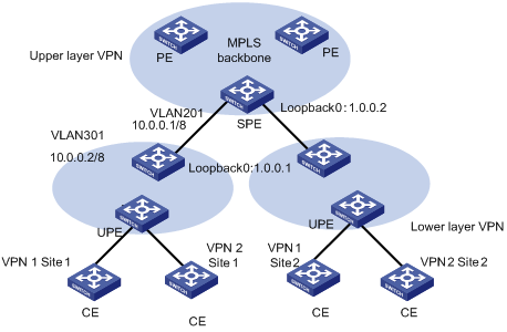
Figure 1-14 Network diagram for hierarchical MPLS L3VPN
III. Configuration procedure
& Note:
This case only illustrates the configurations concerned with PEs in a hierarchical MPLS L3VPN.
1) Configure SPE
# Configure the basic MPLS capability.
[SPE] mpls lsr-id 1.0.0.2
[SPE] mpls
[SPE-mpls] quit
[SPE] mpls ldp
# Configure VPN-instance
[SPE] ip vpn-instance vpn1
[SPE-vpn-vpn1] route-distinguisher 100:1
[SPE-vpn-vpn1] vpn-target 100:1 both
# Configure interfaces (So far as a PE router concerned, its Loopback 0 interface must be assigned with a host address of 32-bit mask.
[SPE] vlan 201
[SPE-vlan201] port gigabitethernet 2/1/1
[SPE-vlan201] quit
[SPE] interface Vlan-interface 201
[SPE-Vlan-interface201] ip address 10.0.0.1 255.0.0.0
[SPE-Vlan-interface201] mpls
[SPE-Vlan-interface201] mpls ldp enable
[SPE-Vlan-interface201] quit
[SPE] interface loopback0
[SPE-LoopBack 0] ip address 1.0.0.2 255.255.255.255
[SPE-LoopBack 0] quit
# Configure BGP
[SPE] bgp 100
[SPE] import direct
[SPE-bgp] group 1 internal
[SPE-bgp] peer 1.0.0.1 group 1
[SPE-bgp] peer 1 connect-interface LoopBack0
[SPE-bgp] ipv4-family vpn-instance vpn1
[SPE--bgp-af-vpn-instance] import direct
[SPE--bgp-af-vpn-instance] quit
[SPE-bgp] ipv4-family vpnv4
[SPE-bgp-af-vpn] peer 1 enable
[SPE-bgp-af-vpn] peer 1.0.0.1 group 1
[SPE-bgp-af-vpn] peer 1.0.0.1 upe
[SPE-bgp-af-vpn] peer 1.0.0.1 default-route-advertise vpn-instance vpn1
[SPE-bgp-af-vpn] quit
[SPE-bgp] quit
# Configure OSPF
[SPE] ospf
[SPE-ospf-1] import-route direct
[SPE-ospf-1] area 0
[SPE-ospf-1-area-0.0.0.0] network 1.0.0.2 0.0.0.0
[SPE-ospf-1-area-0.0.0.0] network 10.0.0.0 0.255.255.255
2) Configure UPE
# Configure the basic MPLS capability.
[UPE] mpls lsr-id 1.0.0.1
[UPE] mpls
[UPE-mpls] quit
[UPE] mpls ldp
# Configure VPN-instance
[UPE] ip vpn-instance vpn1
[UPE-vpn-vpn1] route-distinguisher 100:1
[UPE-vpn-vpn1] vpn-target 100:1 both
# Configure interfaces
[UPE] vlan 301
[UPE-vlan301] port gigabitethernet 2/2/1
[UPE-vlan301] quit
[UPE] interface Vlan-interface 301
[UPE-Vlan-interface301] mpls
[UPE-Vlan-interface301] mpls ldp enable
[UE1-Vlan-interface301] mpls ldp transport-ip interface
[UPE-Vlan-interface301] ip address 10.0.0.2 255.0.0.0
[UPE-Vlan-interface301] quit
[UPE] interface loopback0
[UPE-LoopBack 0] ip address 1.0.0.1 255.255.255.255
# Configure BGP
[UPE] bgp 100
[UPE-bgp] group 1 internal
[UPE-bgp] peer 1.0.0.2 group 1
[UPE-bgp] ipv4-family vpn-instance vpn1
[UPE--bgp-af-vpn-instance] import direct
[UPE-bgp] ipv4-family vpnv4
[UPE-bgp-af-vpn] peer 1 enable
[UPE-bgp-af-vpn] peer 1.0.0.2 group 1
# Configure OSPF
[UPE] ospf
[UPE-ospf-1] import-route direct
[UPE-ospf-1] area 0
[UPE-ospf-1-area-0.0.0.0] network 1.0.0.1 0.0.0.0
[UPE-ospf-1-area-0.0.0.0] network 10.0.0.2 0.255.255.255
[UPE-ospf-1-area-0.0.0.0] quit
1.4.8 OSPF Multi-instance Sham-link Configuration Example
I. Network requirements
As shown in the following picture, a company connects to a WAN through OSPF multi-instance function of H3C router. OSPF is bind to VPN1.MPLS VPN backbone runs between PEs and OSPF runs between PE and CE. Configure a Sham-link between PE1 and PE2 to ensure the traffic between CE1 and CE2 does not pass the Backdoor link that directly connects CE1 and CE2.
II. Network diagram
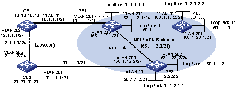
Figure 1-15 Network diagram for OSPF multi-instance
III. Configuration procedure
1) Configure PE1
# Enable MPLS and LDP.
[PE1] mpls lsr-id 50.1.1.1
[PE1] mpls
[PE1-mpls] quit
[PE1] mpls ldp
# Configure VPN-instance.
[PE1] ip vpn-instance vpn1
[PE1-vpn-vpn1] route-distinguisher 2:1
[PE1-vpn-vpn1] vpn-target 100:1 export-extcommunity
[PE1-vpn-vpn1] vpn-target 100:1 import-extcommunity
# Configure VLAN interface.
[PE1] vlan 203
[PE1-vlan203] port gigabitethernet 2/1/3
[PE1-vlan203] quit
[PE1] interface Vlan-interface 203
[PE1-Vlan-interface203] ip address 168.1.12.1 255.255.255.0
[PE1-Vlan-interface203] mpls
[PE1-Vlan-interface203] mpls ldp enable
[PE1-Vlan-interface203] quit
[PE1] vlan 201
[PE1-vlan201] port gigabitethernet 2/1/1
[PE1-vlan201] quit
[PE1] interface Vlan-interface 201
[PE1-Vlan-interface201] ip binding vpn-instance vpn1
[PE1-Vlan-interface201] ip address 10.1.1.2 255.255.255.0
[PE1-Vlan-interface201] ospf cost 1
[PE1-Vlan-interface201] quit
[PE1] vlan 202
[PE1-vlan202] port gigabitethernet 2/1/2
[PE1-vlan202] quit
[PE1] interface Vlan-interface 202
[PE1-Vlan-interface202] ip address 168.1.13.1 255.255.255.0
[PE1-Vlan-interface202] ospf cost 1
[PE1-Vlan-interface202] mpls
[PE1-Vlan-interface202] mpls ldp enable
[PE1-Vlan-interface202] mpls ldp transport-ip interface
[PE1-Vlan-interface202] quit
[PE1] interface loopback0
[PE1-LoopBack0] ip binding vpn-instance vpn1
[PE1-LoopBack0] ip address 1.1.1.1 255.255.255.255
[PE1-LoopBack0] quit
[PE1] interface loopback1
[PE1-LoopBack1] ip address 50.1.1.1 255.255.255.255
# Configure BGP Peer.
[PE1] bgp 100
[PE1-bgp] undo synchronization
[PE1-bgp] group fc internal
[PE1-bgp] peer 50.1.1.2 group fc
[PE1-bgp] peer 50.1.1.2 connect-interface LoopBack1
[PE1-bgp] peer 50.1.1.3 group fc
# Configure BGP and import OSPF routing and direct-connect route.
[PE1-bgp] ipv4-family vpn-instance vpn1
[PE1-bgp-af-vpn-instance] import-route ospf 100
[PE1-bgp-af-vpn-instance] import-route ospf-ase 100
[PE1-bgp-af-vpn-instance] import-route ospf-nssa 100
[PE1-bgp-af-vpn-instance] import-route direct
[PE1-bgp-af-vpn-instance] undo synchronization
# Create and activate Peer in MBGP.
[PE1-bgp-af-vpn] ipv4-family vpnv4
[PE1-bgp-af-vpn] peer fc enable
[PE1-bgp-af-vpn] peer fc advertise-community
[PE1-bgp-af-vpn] peer 50.1.1.2 group fc
# Bind OSPF process to VPN-instance.
[PE1] ospf 100 router-id 1.1.1.1 vpn-instance vpn1
[PE1-ospf-100] import-route bgp
[PE1-ospf-100] area 0.0.0.0
[PE1-ospf-100-area-0.0.0.0] network 10.1.1.0 0.0.0.255
# Configuring Sham-link
[PE1-ospf-100-area-0.0.0.1] sham-link 1.1.1.1 2.2.2.2
# Configure the routes distributed to PE2 and PE3.
[PE1] ospf 1000
[PE1-ospf-1000] area 0
[H3C-ospf-1000-area-0.0.0.0] network 168.12.1.0 0.0.0.255
[H3C-ospf-1000-area-0.0.0.0] network 50.1.1.1 0.0.0.0
2) Configure PE2
# Enable MPLS and LDP.
[PE2] mpls lsr-id 50.1.1.2
[PE2] mpls
[PE2-mpls] quit
[PE2] mpls ldp
# Configure VPN-instance VPN1.
[PE2] ip vpn-instance vpn1
[PE2-vpn-vpn1] route-distinguisher 2:1
[PE2-vpn-vpn1] vpn-target 100:1 export-extcommunity
[PE2-vpn-vpn1] vpn-target 100:1 import-extcommunity
# Configure VLAN interface.
[PE2] vlan 203
[PE2-vlan203] port gigabitethernet 2/1/3
[PE2-vlan203] quit
[PE2] interface Vlan-interface 203
[PE2-Vlan-interface203] ip address 168.1.12.2 255.255.255.0
[PE2-Vlan-interface203] mpls
[PE2-Vlan-interface203] mpls ldp enable
[PE2-Vlan-interface203] quit
[PE2] vlan 201
[PE2-vlan201] port gigabitethernet 2/1/1
[PE2-vlan201] quit
[PE2] interface Vlan-interface 201
[PE2-Vlan-interface201] ip binding vpn-instance vpn1
[PE2-Vlan-interface201] ip address 20.1.1.2 255.255.255.0
[PE2-Vlan-interface201] ospf cost 1
[PE2-Vlan-interface201] quit
[PE2] vlan 202
[PE2-vlan202] port gigabitethernet 2/1/2
[PE2-vlan202] quit
[PE2] interface Vlan-interface 202
[PE2-Vlan-interface202] ip address 168.1.23.2 255.255.255.0
[PE2-Vlan-interface202] ospf cost 1
[PE2-Vlan-interface202] mpls
[PE2-Vlan-interface202] mpls ldp enable
[PE2-Vlan-interface202] quit
[PE2] interface LoopBack0
[PE2-LoopBack0] ip binding vpn-instance vpn1
[PE2-LoopBack0] ip address 2.2.2.2 255.255.255.255
[PE2-LoopBack0] quit
[PE2] interface LoopBack1
[PE2-LoopBack1] ip address 50.1.1.2 255.255.255.255
# Configure BGP.
[PE2] bgp 100
[PE2-bgp] undo synchronization
[PE2-bgp] group fc internal
[PE2-bgp] peer 50.1.1.1 group fc
[PE2-bgp] peer 50.1.1.1 connect-interface LoopBack1
[PE2-bgp] peer 50.1.1.3 group fc
# Configure VPN-instance and import OSPF and direct-connect route.
[PE2-bgp] ipv4-family vpn-instance vpn1
[PE2-bgp-af-vpn-instance] import-route direct
[PE2-bgp-af-vpn-instance] import-route ospf-nssa 100
[PE2-bgp-af-vpn-instance] import-route ospf-ase 100
[PE2-bgp-af-vpn-instance] import-route ospf 100
[PE2-bgp-af-vpn-instance] undo synchronization
# Configure MBGP and enable Peer.
[PE2-bgp-af-vpn] ipv4-family vpnv4
[PE2-bgp-af-vpn] peer fc enable
[PE2-bgp-af-vpn] peer fc advertise-community
[PE2-bgp-af-vpn] peer 50.1.1.1 group fc
# Configure OSPF and import BGP and direct-connect route.
[PE2] ospf 100 router-id 2.2.2.2 vpn-instance vpn1
[PE2-ospf-100] import-route bgp
[PE2-ospf-100] import-route static
[PE2-ospf-100] area 0.0.0.0
[PE2-ospf-100-area-0.0.0.0] network 20.1.1.0 0.0.0.255
# Configuring Sham-link
[PE2-ospf-100-area-0.0.0.0] sham-link 2.2.2.2 1.1.1.1
# Configure static route to PE1 and PE3.
[PE2] ip route-static 50.1.1.1 255.255.255.255 168.1.12.1
[PE2] ip route-static 50.1.1.3 255.255.255.255 168.1.23.3
# Configure the routes distributed to PE1 and PE3.
[PE1] ospf 1000
[PE1-ospf-1000]area 0
[H3C-ospf-1000-area-0.0.0.0] network 168.12.1.0 0.0.0.255
[H3C-ospf-1000-area-0.0.0.0] network 50.1.1.1 0.0.0.0
3) Configure CE1
# Configure interfaces
[CE1] vlan 202
[CE1-vlan202] port gigabitethernet 2/1/2
[CE1-vlan202] quit
[CE1] interface Vlan-interface 202
[CE1-Vlan-interface202] ip address 12.1.1.1 255.255.255.0
[CE1-Vlan-interface202] ospf cost 100
[CE1-Vlan-interface202] quit
[CE1] vlan 201
[CE1-vlan201] port gigabitethernet 2/1/1
[CE1-vlan201] quit
[CE1] interface Vlan-interface 201
[CE1-Vlan-interface201] ip address 10.1.1.1 255.255.255.0
[CE1-Vlan-interface201] ospf cost 1
# Configure OSPF.
[CE1] ospf 100 router-id 10.10.10.129
[CE1-ospf-100] import-route direct
[CE1-ospf-100] area 0.0.0.0
[CE1-ospf-100-area-0.0.0.0] network 10.1.1.0 0.0.0.255
[CE1-ospf-100-area-0.0.0.0] network 12.1.1.0 0.0.0.255
4) Configure CE2
# Configure interface.
[CE2] vlan 202
[CE2-vlan202] port gigabitethernet 2/1/2
[CE2-vlan202] quit
[CE2] interface Vlan-interface 202
[CE2-Vlan-interface202] ip address 12.1.1.2 255.255.255.0
[CE2-Vlan-interface202] ospf cost 100
[CE2-Vlan-interface202] quit
[CE2] vlan 201
[CE2-vlan201] port gigabitethernet 2/1/1
[CE2-vlan201] quit
[CE2] interface Vlan-interface 201
[CE2-Vlan-interface201] ip address 20.1.1.1 255.255.255.0
[CE2-Vlan-interface201] ospf cost 1
# Configure OSPF.
[CE2] ospf 100 router-id 20.20.20.20
[CE2-ospf-100] area 0.0.0.0
[CE2-ospf-100-area-0.0.0.0] network 12.1.1.0 0.0.0.255
[CE2-ospf-100-area-0.0.0.0] network 20.1.1.0 0.0.0.255
1.4.9 Nested MPLS L3VPN Configuration Example
I. Network requirements
A VPN user has multiple nodes to access the service provider's MPLS L3VPN backbone network. And this VPN is divided into three sub-VPNs: VPN1, VPN2 and VPN3.
Some of the nodes of these sub-VPNs directly access a PE in the network, and some access a PE through the father VPN. That is, the adopted network structure is unsymmetrical.
This example mainly describes the configuration of VPN1; the configuration of other sub-VPNs is similar.
II. Network diagram
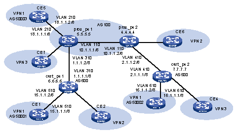
Figure 1-16 Network diagram for nested VPN
III. Configuration procedure
& Note:
This procedure omits part of the configuration for CE router.
1) Configure IGP on the service provider's backbone network.
# Configure prov_pe1.
<H3C> system-view
[H3C] sysname prov_pe1
[prov_pe1] interface LoopBack0
[prov_pe1-LoopBack0] ip address 5.5.5.5 255.255.255.255
[prov_pe1-LoopBack0] quit
[prov_pe1] vlan 110
[prov_pe1-vlan110] interface vlan 110
[prov_pe1-Vlan-interface110] ip address 10.1.1.1 255.0.0.0
[prov_pe1-Vlan-interface110] quit
[prov_pe1] ospf
[prov_pe1-ospf] area 0
[prov_pe1-ospf-area-0.0.0.0] network 5.5.5.5 0.0.0.0
[prov_pe1-ospf-area-0.0.0.0] network 10.0.0.0 0.255.255.255
# Configure prov_pe2.
<H3C> system-view
[H3C] sysname prov_pe2
[prov_pe2] interface LoopBack0
[prov_pe2-LoopBack0] ip address 4.4.4.4 255.255.255.255
[prov_pe2-LoopBack0] quit
[prov_pe1] vlan 110
[prov_pe1-vlan110] interface vlan-interface 110
[prov_pe1-Vlan-interface110] ip address 10.1.1.2 255.0.0.0
[prov_pe1-Vlan-interface110] quit
[prov_pe2] ospf
[prov_pe2-ospf] area 0
[prov_pe2-ospf-area-0.0.0.0] network 4.4.4.4 0.0.0.0
[prov_pe2-ospf-area-0.0.0.0] network 10.0.0.0 0.255.255.255
Configure basic MPLS capability and MPLS LDP on the backbone network.
# Configure prov_pe1.
[prov_pe1] mpls lsr-id 5.5.5.5
[prov_pe1] mpls ldp
[prov_pe1] interface vlan 110
[prov_pe1- Vlan-interface110] mpls
[prov_pe1- Vlan-interface110] mpls ldp enable
[prov_pe1- Vlan-interface110] quit
# Configure prov_pe2.
[prov_pe2] mpls lsr-id 4.4.4.4
[prov_pe2] mpls ldp
[prov_pe2] interface vlan 110
[prov_pe2- Vlan-interface110] mpls
[prov_pe2- Vlan-interface110] mpls ldp enable
[prov_pe2- Vlan-interface110] quit
Configure IBGP between provider PEs.
# Configure prov_pe1.
[prov_pe1] bgp 100
[prov_pe1-bgp] group ibgp internal
[prov_pe1-bgp] peer 4.4.4.4 group ibgp
[prov_pe1-bgp] peer 4.4.4.4 connect-interface LoopBack0
[prov_pe1-bgp] ipv4-family vpnv4
[prov_pe1-bgp-af-vpn] peer ibgp enable
[prov_pe1-bgp-af-vpn] peer ibgp next-hop-local
[prov_pe1-bgp-af-vpn] peer 4.4.4.4 group ibgp
[prov_pe1-bgp-af-vpn] quit
[prov_pe1-bgp] quit
# Configure prov_pe2.
[prov_pe2] bgp 100
[prov_pe2-bgp] group ibgp internal
[prov_pe2-bgp] peer 5.5.5.5 group ibgp
[prov_pe2-bgp] peer 5.5.5.5 connect-interface LoopBack0
[prov_pe2-bgp] ipv4-family vpnv4
[prov_pe2-bgp-af-vpn] peer ibgp enable
[prov_pe2-bgp-af-vpn] peer ibgp next-hop-local
[prov_pe2-bgp-af-vpn] peer 5.5.5.5 group ibgp
[prov_pe2-bgp-af-vpn] quit
[prov_pe2-bgp] quit
2) Create a VPN instance on provider PEs to access customer PEs and directly connected user CEs.
# Configure prov_pe1.
[prov_pe1] ip vpn-instance customer_vpn
[prov_pe1-vpn-instance] route-distinguisher 3:3
[prov_pe1-vpn-instance] vpn-target 3:3 export-community
[prov_pe1-vpn-instance] quit
[prov_pe1] ip vpn-instance vpn1
[prov_pe1-vpn-instance] route-distinguisher 1:1
[prov_pe1-vpn-instance] vpn-target 1:1
[prov_pe1-vpn-instance] vpn-target 3:3
[prov_pe1-vpn-instance] quit
[prov_pe1] vlan 310
[prov_pe1] interface vlan 310
[prov_pe1-Vlan-interface310] ip binding vpn-instance customer_vpn
[prov_pe1-Vlan-interface310] ip address 1.1.1.2 255.0.0.0
[prov_pe1- Vlan-interface310] mpls
[prov_pe1- Vlan-interface310] quit
[prov_pe1] interface vlan 210
[prov_pe1-Vlan-interface210] ip binding vpn-instance vpn1
[prov_pe1- Vlan-interface210] ip address 18.1.1.1 255.0.0.0
[prov_pe1- Vlan-interface210] quit
# Configure prov_pe2.
[prov_pe2] ip vpn-instance customer_vpn
[prov_pe2-vpn-instance] route-distinguisher 3:3
[prov_pe2-vpn-instance] vpn-target 3:3
[prov_pe2-vpn-instance] quit
[prov_pe2] interface vlan 410
[prov_pe2-Vlan-interface410] ip binding vpn-instance customer_vpn
[prov_pe2- Vlan-interface410] ip address 2.1.1.2 255.0.0.0
[prov_pe2- Vlan-interface410] mpls
[prov_pe2- Vlan-interface410] quit
# Configure cust_pe1.
<H3C> system-view
[H3C] sysname cust_pe1
[cust_pe1] interface LoopBack0
[cust_pe1-LoopBack0] ip address 6.6.6.6 255.255.255.255
[cust_pe1-LoopBack0] quit
[cust_pe1] mpls lsr-id 6.6.6.6
[cust_pe1] interface vlan 310
[cust_pe1-Vlan-interface310] ip address 1.1.1.1 255.0.0.0
[cust_pe1- Vlan-interface310] mpls
[cust_pe1- Vlan-interface310] quit
# Configure cust_pe2.
<H3C> system-view
[H3C] sysname cust_pe2
[cust_pe2] interface LoopBack0
[cust_pe2-LoopBack0] ip address 7.7.7.7 255.255.255.255
[cust_pe2-LoopBack0] quit
[cust_pe2] mpls lsr-id 7.7.7.7
[cust_pe2] interface vlan 410
[cust_pe2-Vlan-interface410] ip address 2.1.1.1 255.0.0.0
[cust_pe2-Vlan-interface410] mpls
[cust_pe2-Vlan-interface410] quit
3) Configure EBGP between provider PE and customer PE.
# Configure prov_pe1 to access the corresponding Customer PE.
[prov_pe1] route-policy comm permit node 10
[prov_pe1-route-policy-comm-10] if-match vpn-target 1:1
[prov_pe1-route-policy-comm-10] quit
[prov_pe1] bgp 100
[prov_pe1-bgp] ipv4-family vpn-instance customer_vpn
[prov_pe1-bgp-af-vpn-instance] group ebgp external
[prov_pe1-bgp-af-vpn-instance] undo peer ebgp enable
[prov_pe1-bgp-af-vpn-instance] peer 1.1.1.1 group ebgp as-number 600
[prov_pe1-bgp] ipv4-family vpnv4
[prov_pe1-bgp-af-vpn] nesting-vpn
[prov_pe1-bgp-af-vpn] peer ebgp vpn-instance customer_vpn enable
[prov_pe1-bgp-af-vpn] peer 1.1.1.1 vpn-instance customer_vpn group ebgp
[prov_pe1-bgp-af-vpn] peer 1.1.1.1 vpn-instance customer_vpn route-policy comm import
[prov_pe1-bgp-af-vpn] quit
# Configure prov_pe1 to access CE5
[prov_pe1-bgp] ipv4-family vpn-instance vpn1
[prov_pe1-bgp-af-vpn-instance] group ebgp external
[prov_pe1-bgp-af-vpn-instance] peer 18.1.1.2 group ebgp as-number 50003
# Configure prov_pe2 to access the corresponding Customer PE.
[prov_pe2] route-policy com2 permit node 10
[prov_pe2-route-policy-com2-10] if-match vpn-target 1:1
[prov_pe2-route-policy-com2-10] quit
[prov_pe2] bgp 100
[prov_pe2-bgp] ipv4-family vpn-instance customer_vpn
[prov_pe2-bgp-af-vpn-instance] group ebgp external
[prov_pe2-bgp-af-vpn-instance] undo peer ebgp enable
[prov_pe2-bgp-af-vpn-instance] peer 2.1.1.1 group ebgp as-number 500
[prov_pe2-bgp] ipv4-family vpnv4
[prov_pe2-bgp-af-vpn] nesting-vpn
[prov_pe2-bgp-af-vpn] peer ebgp vpn-instance customer_vpn enable
[prov_pe2-bgp-af-vpn] peer 2.1.1.1 vpn-instance customer_vpn group ebgp
[prov_pe2-bgp-af-vpn] peer 2.1.1.1 vpn-instance customer_vpn route-policy com2 import
# Configure cust_pe1
[cust_pe1] bgp 600
[cust_pe1-bgp] group ebgp external
[cust_pe1-bgp] undo peer ebgp enable
[cust_pe1-bgp] peer 1.1.1.2 group ebgp as-number 100
[cust_pe1-bgp] ipv4-family vpnv4
[cust_pe1-bgp-af-vpn] peer ebgp enable
[cust_pe1-bgp-af-vpn] peer 1.1.1.2 group ebgp
# Configure cust_pe2
[cust_pe2] bgp 500
[cust_pe2-bgp] group ebgp external
[cust_pe2-bgp] undo peer ebgp enable
[cust_pe2-bgp] peer 2.1.1.2 group ebgp as-number 100
[cust_pe2-bgp] ipv4-family vpnv4
[cust_pe2-bgp-af-vpn] peer ebgp enable
[cust_pe2-bgp-af-vpn] peer 2.1.1.2 group ebgp
4) On each Customer PE, configure the sub-VPN that accesses the network through the Customer PE.
# Configure cust_pe1.
[cust_pe1] ip vpn-instance vpn1
[cust_pe1-vpn-instance] route-distinguisher 1:1
[cust_pe1-vpn-instance] vpn-target 1:1
[cust_pe1-vpn-instance] quit
[cust_pe1] interface vlan 510
[cust_pe1-Vlan-interface510] ip binding vpn-instance vpn1
[cust_pe1- Vlan-interface510] ip address 15.1.1.2 255.0.0.0
[cust_pe1-Vlan-interface510] quit
[cust_pe1] bgp 600
[cust_pe1-bgp] undo peer ebgp enable
[cust_pe1-bgp] ipv4-family vpn-instance vpn1
[cust_pe1-bgp-af-vpn-instance] group cegroup external
[cust_pe1-bgp-af-vpn-instance] peer 15.1.1.1 group cegroup as-number 50001
[cust_pe1-bgp-af-vpn-instance] quit
[cust_pe1-bgp] quit
# Configure cust_pe2
[cust_pe2] ip vpn-instance vpn1
[cust_pe2-vpn-instance] route-distinguisher 1:1
[cust_pe2-vpn-instance] vpn-target 1:1
[cust_pe2] interface vlan 610
[cust_pe2-Vlan-interface610] ip binding vpn-instance vpn1
[cust_pe2-Vlan-interface610] ip address 16.1.1.2 255.0.0.0
[cust_pe2-Vlan-interface510] quit
[cust_pe2] bgp 500
[cust_pe2-bgp] undo peer ebgp enable
[cust_pe2-bgp] ipv4-family vpn-instance vpn1
[cust_pe2-bgp-af-vpn-instance] group cegroup external
[cust_pe2-bgp-af-vpn-instance] peer 16.1.1.1 group cegroup as-number 50002
[cust_pe2-bgp-af-vpn-instance] quit
[cust_pe2-bgp] quit
1.4.10 OSPF Multi-instance CE Configuration Example
I. Network requirements
CE router in a VPN achieves service isolation by configuring multiple VPN instances.
II. Network diagram
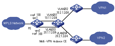
Figure 1-17 Network diagram for OSPF multi-instance CE configuration
III. Configuration procedure
1) Configuring CE router
# Configure instance VPN1
[CE] ip vpn-instance vpn1
[CE-vpn-vpn1] route-distinguisher 100:1
[CE-vpn-vpn1] vpn-target 100:1 export-extcommunity
[CE-vpn-vpn1] vpn-target 100:1 import-extcommunity
# Configure instance VPN2
[CE] ip vpn-instance vpn2
[CE-vpn-vpn2] route-distinguisher 200:1
[CE-vpn-vpn2] vpn-target 200:1 export-extcommunity
[CE-vpn-vpn2] vpn-target 200:1 import-extcommunity
# Configure VLAN201.
[CE] vlan 201
[CE-vlan201] port gigabitethernet 2/1/1
[CE-vlan201] quit
[CE] interface Vlan-interface 201
[CE-Vlan-interface201] ip binding vpn-instance vpn1
[CE-Vlan-interface201] ip address 10.1.1.2 255.255.255.0
# Configure VLAN202.
[CE] vlan 202
[CE-vlan202] port gigabitethernet 2/1/2
[CE-vlan202] quit
[CE] interface Vlan-interface 202
[CE-Vlan-interface202] ip binding vpn-instance vpn1
[CE-Vlan-interface202] ip address 10.2.1.2 255.255.255.0
[CE-Vlan-interface202] ospf cost 100
# Configure VLAN203.
[CE] vlan 203
[CE-vlan203] port gigabitethernet 2/1/3
[CE-vlan203] quit
[CE] interface Vlan-interface 203
[CE-Vlan-interface203] ip binding vpn-instance vpn2
[CE-Vlan-interface203] ip address 20.1.1.2 255.255.255.0
# Configure VLAN204.
[CE] vlan 204
[CE-vlan204] port gigabitethernet 2/1/4
[CE-vlan204] quit
[CE] interface Vlan-interface 204
[CE-Vlan-interface204] ip binding vpn-instance vpn2
[CE-Vlan-interface204] ip address 20.2.1.2 255.255.255.0
# Configure OSPF 100.
[CE] ospf 100 vpn-instance vpn1
[CE-ospf-100] vpn-instance-capability simple
[CE-ospf-100] area 0.0.0.0
[CE-ospf-100-area-0.0.0.0] network 10.1.1.0 0.0.0.255
[CE-ospf-100-area-0.0.0.0] network 10.2.1.0 0.0.0.255
# Configure OSPF 300.
[CE] ospf 300 vpn-instance vpn2
[CE-ospf-300] vpn-instance-capability simple
[CE-ospf-300] area 0.0.0.1
[CE-ospf-300-area-0.0.0.1] network 20.1.1.0 0.0.0.255
[CE-ospf-300-area-0.0.0.1] network 20.2.1.0 0.0.0.255
1.4.11 Multi-Role Host Configuration Example
I. Network requirements
CE1 and CE3 belong to VPN1, and CE2 belong to VPN2.
The host PC2 with the IP address of 172.16.0.1 accesses the network through CE2. As a multi-role host, it can access both VPN1 and VPN2.
II. Network diagram
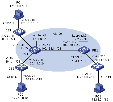
Figure 1-18 Network diagram for multi-role host application
III. Configuration procedure
1) Configure OSPF as the IGP protocol on the MPLS backbone network.
# Configure OSPF on PE1:
[PE1] interface loopback 0
[PE1-LoopBack0] ip address 1.1.1.9 32
[PE1-LoopBack0] quit
[PE1] vlan 110
[PE1-vlan110] interface vlan-interface 110
[PE1-Vlan-interface110] ip address 192.168.1.1 24
[PE1-Vlan-interface110] quit
[PE1] ospf
[PE1-ospf-1] area 0
[PE1-ospf-1-area-0.0.0.0] network 192.168.1.0 0.0.0.255
[PE1-ospf-1-area-0.0.0.0] network 1.1.1.9 0.0.0.0
[PE1-ospf-1-area-0.0.0.0] quit
[PE1-ospf-1] quit
# Configure OSPF on PE2:
[PE2] interface loopback 0
[PE2-LoopBack0] ip address 2.2.2.9 32
[PE2-LoopBack0] quit
[PE2] vlan 110
[PE2-vlan110] interface vlan-interface 110
[PE1-Vlan-interface110] ip address 192.168.1.2 24
[PE2-Vlan-interface110] quit
[PE2] ospf
[PE2-ospf-1] area 0
[PE2-ospf-1-area-0.0.0.0] network 192.168.1.0 0.0.0.255
[PE2-ospf-1-area-0.0.0.0] network 2.2.2.9 0.0.0.0
[PE2-ospf-1-area-0.0.0.0] quit
[PE2-ospf-1] quit
2) Configure basic MPLS capability and create VPN instances.
# Configure basic MPLS capability on PE1:
[PE1] mpls lsr-id 1.1.1.9
[PE1-mpls] lsp-trigger all
[PE1-mpls] quit
[PE1] mpls ldp
[PE1-mpls-ldp] quit
[PE1] vlan 110
[PE1-vlan110] interface vlan-interface 110
[PE1-Vlan-interface110] mpls
[PE1-Vlan-interface110] mpls ldp enable
[PE1-Vlan-interface110] quit
# Create VPN instances for VPN1 and VPN2 on PE1, bind the address of the interface of VLAN310 to VPN1 and VPN2.
[PE1] ip vpn-instance vpn1
[PE1-vpn-vpn1] route-distinguisher 100:1
[PE1-vpn-vpn1] vpn-target 100:1 both
[PE1-vpn-vpn1] quit
[PE1] ip vpn-instance vpn2
[PE1-vpn-vpn2] route-distinguisher 100:2
[PE1-vpn-vpn2] vpn-target 100:2 both
[PE1-vpn-vpn2] quit
[PE1] vlan 310
[PE1-vlan310] interface vlan-interface 310
[PE1-Vlan-interface310] ip binding vpn-instance vpn1
[PE1-Vlan-interface310] ip address 20.2.1.2 24
[PE1-Vlan-interface310] quit
[PE1] vlan 210
[PE1-vlan210] interface vlan-interface 210
[PE1-Vlan-interface210] ip binding vpn-instance vpn2
[PE1-Vlan-interface210] ip address 20.1.1.2 24
[PE1-Vlan-interface210] quit
# Configure basic MPLS capability on PE2.
[PE2] mpls lsr-id 2.2.2.9
[PE2-mpls] lsp-trigger all
[PE2-mpls] quit
[PE2] mpls ldp
[PE2-mpls-ldp] quit
[PE2] vlan 110
[PE2-vlan110] interface vlan-interface 110
[PE2-Vlan-interface110] mpls
[PE2-Vlan-interface110] mpls ldp
[PE2-Vlan-interface110] quit
# Create a VPN instance for VPN1 on PE2, and bind the address of the interface of VLAN210 to VPN1.
[PE2] ip vpn-instance vpn1
[PE2-vpn-vpn1] route-distinguisher 300:1
[PE2-vpn-vpn1] vpn-target 100:1 both
[PE2-vpn-vpn1] quit
[PE2] vlan 210
[PE2-vlan210] interface vlan-interface 210
[PE2-Vlan-interface210] ip binding vpn-instance vpn1
[PE2-Vlan-interface210] ip address 20.3.1.2 24
[PE2-Vlan-interface210] quit
Configure BGP.
# Configure CE1:
[CE1] vlan 310
[CE1-vlan310] interface vlan-interface 310
[CE1-Vlan-interface310] ip address 20.2.1.1 24
[CE1-Vlan-interface310] quit
[CE1] bgp 65410
[CE1-bgp] import-route direct
[CE1-bgp] group 10 external
[CE1-bgp] peer 20.2.1.2 group 10 as-number 100
[CE1-bgp] quit
# Configure CE2:
[CE2] vlan 210
[CE2-vlan210] interface vlan-interface 210
[CE2-Vlan-interface210] ip address 20.1.1.1 24
[CE2-Vlan-interface210] quit
# Configure CE3:
[CE3] vlan 210
[CE3-vlan210] interface vlan-interface 210
[CE3-Vlan-interface210] ip address 20.3.1.1 24
[CE3-Vlan-interface210] quit
[CE3] bgp 65430
[CE3-bgp] import-route direct
[CE3-bgp] group 10 external
[CE3-bgp] peer 20.3.1.2 group 10 as-number 100
[CE3-bgp] quit
# Configure PE1: Configure PE1 to be the IBGP peer of PE2 in BGP-VPNv4 sub-address family view. Configure PE1 to be the EBGP peer of CE1 in the BGP VPN1 instance view. Configure a static route between CE2 and PE1 to enable them to communicate with each other. Import a static route in BGP VPN2 instance view to advertise it to the remote PE.
[PE1] bgp 100
[PE1-bgp] group 10
[PE1-bgp] peer 2.2.2.9 group 10
[PE1-bgp] peer 2.2.2.9 connect-interface loopback 0
[PE1-bgp] ipv4-family vpnv4
[PE1-bgp-af-vpn] peer 10 enable
[PE1-bgp-af-vpn] peer 2.2.2.9 group 10
[PE1-bgp-af-vpn] quit
[PE1-bgp] ipv4-family vpn-instance vpn1
[PE1-bgp-af-vpn-instance] import-route direct
[PE1-bgp-af-vpn-instance] group 20 external
[PE1-bgp-af-vpn-instance] peer 20.2.1.1 group 20 as-number 65410
[PE1-bgp-af-vpn-instance] quit
[PE1-bgp] ipv4-family vpn-instance vpn2
[PE1-bgp-af-vpn-instance] import-route direct
[PE1-bgp-af-vpn-instance] import-route static
# Configure PE2: set up IBGP peer relation with PE1 in BGP-VPNv4 sub-address family view; set up EBGP peer relation with CE3 in BGP-VPN instance view.
[PE2] bgp 100
[PE2-bgp] group 10
[PE2-bgp] peer 1.1.1.9 group 10
[PE2-bgp] peer 1.1.1.9 connect-interface loopback 0
[PE2-bgp] ipv4-family vpnv4
[PE2-bgp-af-vpn] peer 10 enable
[PE2-bgp-af-vpn] peer 1.1.1.9 group 10
[PE2-bgp-af-vpn] quit
[PE2-bgp] ipv4-family vpn-instance vpn1
[PE2-bgp-af-vpn-instance] import-route direct
[PE2-bgp-af-vpn-instance] group 20 external
[PE2-bgp-af-vpn-instance] peer 20.3.1.1 group 20 as-number 65430
[PE2-bgp-af-vpn-instance] quit
[PE2-bgp] quit
Configure multi-role host feature: If a routing protocol is employed between CE2 and PE1, configure PE1 not to advertise any route information to CE2 to avoid route loops. Following depicts a way to achieve this. You can also avoid route loops in other ways. Directly configure a static route to PC2 on PE1 if no routing protocol is employed between PE1 and CE2.
# Configure a default route pointing to PE1 on CE2.
[CE2] ip route-static 0.0.0.0 0.0.0.0 20.1.1.2
# Configure a multiple-role host route on PE1.
[PE1] ip route-static vpn-instance vpn1 172.16.0.0 16 vpn2 20.1.1.1
# Import the route of VPN1 to VPN2 using the RT attribute.
[PE1] ip vpn-instance vpn2
[PE1-vpn-vpn2] vpn-target 100:1 import-extcommunity
1.4.12 FIB Entry Application Configuration Example
I. Networking requirements
This configuration example applies to an MPLS networking environment where there is a need to configure a dynamic routing protocol to advertise routes and to configure a static LSP for MPLS forwarding.
Make sure that the FIB entries generated by the dynamic routing protocol will not affect the FIB entries advertised by the static LSP for normal MPLS forwarding. After the static LSP is removed, the FIB entries generated by the dynamic routing protocol can be used for IP forwarding.
II. Networking diagram
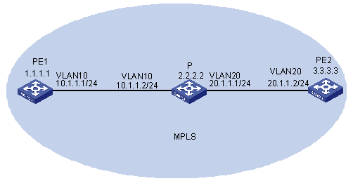
Figure 1-19 Networking diagram for MPLS configuration
III. Configuration procedure
1) Configure PE1
# Enable MPLS.
[PE1] mpls lsr-id 1.1.1.1
[PE1] mpls
# Configure the loopback interface.
[PE1] interface LoopBack 0
[PE_1-LoopBack0] ip address 1.1.1.1 255.255.255.255
# Configure the virtual VLAN interface.
[PE1] vlan 10
[PE1-vlan10] port gigabitethernet 2/1/1
[PE1-vlan10] quit
[PE1] interface Vlan-interface 10
[PE1-Vlan-interface10] ip address 10.1.1.1 255.255.255.0
[PE1-Vlan-interface10] ospf cost 1
[PE1-Vlan-interface10] mpls
[PE1-Vlan-interface10] quit
# Enable OSPF on the loopback interface and the interface through which PE1 connects to the P device for intra-MPLS domain interworking.
[PE1] Router-id 1.1.1.1
[PE1] ospf
[PE1-ospf-1] area 0
[PE1-ospf-1-area-0.0.0.0] network 1.1.1.1 0.0.0.0
[PE1-ospf-1-area-0.0.0.0] network 10.1.1.1 0.0.0.255
[PE1-ospf-1-area-0.0.0.0] quit
[PE1-ospf-1] quit
# Configure the static LSP to PE2.
[PE1] mpls
[PE1-mpls] static-lsp ingress lsp1 destination 3.3.3.3 32 nexthop 10.1.1.2 out-label 50
2) Configure PE2
& Note:
The configuration of PE2 is similar to that of PE1. The following takes the configuration of a static LSP as an example. Other configurations are omitted.
# Configure the static LSP to PE1.
[PE2] mpls
[PE2-mpls] static-lsp ingress lsp2 destination 1.1.1.1 32 nexthop 20.1.1.1 out-label 60
3) Configure the P device
# Enable MPLS.
[P] mpls lsr-id 2.2.2.2
[P] mpls
# Configure the loopback interface.
[PE1] interface LoopBack 0
[PE_1-LoopBack0] ip address 2.2.2.2 255.255.255.255
# Configure the virtual VLAN interface.
[P] vlan 10
[P-vlan10] port gigabitethernet 2/1/1
[P-vlan10] quit
[P] interface Vlan-interface 10
[P-Vlan-interface10] ip address 10.1.1.2 255.255.255.0
[P-Vlan-interface10] ospf cost 1
[P-Vlan-interface10] mpls
[P-Vlan-interface10] quit
[P] vlan 20
[P-vlan20] port gigabitethernet 2/1/2
[P-vlan20] quit
[P] interface Vlan-interface 20
[P-Vlan-interface20] ip address 20.1.1.1 255.255.255.0
[P-Vlan-interface20] ospf cost 1
[P-Vlan-interface20] mpls
[P-Vlan-interface20] quit
# Enable OSPF on the loopback interface and the interfaces through which the P device connects to PE1 and PE2 for intra-MPLS domain interworking.
[P] Router-id 1.1.1.1
[P] ospf
[P-ospf-1] area 0
[P-ospf-1-area-0.0.0.0] network 2.2.2.2 0.0.0.0
[P-ospf-1-area-0.0.0.0] network 10.1.1.2 0.0.0.255
[P-ospf-1-area-0.0.0.0] network 20.1.1.1 0.0.0.255
[P-ospf-1-area-0.0.0.0] quit
[P-ospf-1] quit
# Configure the static LSPs to PE1 and PE2.
[P] mpls
[P-mpls] static-lsp transit lsp1 incoming-interface Vlan-interface 10 in-label
50 nexthop 20.1.1.2 out-label 3
[P-mpls] static-lsp transit lsp2 incoming-interface Vlan-interface 20 in-label
60 nexthop 10.1.1.1 out-label 3
IV. Verify the configuration
<PE_1> display fib 3.3.3.3
Destination/Mask Nexthop Flag TimeStamp Interface ACTIVE
3.3.3.3/32 10.1.1.2 S t[0] Vlan-interface10 YES
[PE_1] display fib all
Route Entry Count: 2
Destination/Mask Nexthop Flag TimeStamp Interface ACTIVE
3.3.3.3/32 10.1.1.2 S t[0] Vlan-interface10 YES
3.3.3.3/32 10.1.1.2 GHU t[0] Vlan-interface10 NO
1.5 Troubleshooting MPLS L3VPN Configuration
I. Symptom 1
In central server topology networking mode, the local end switch (spoke PE) cannot learn the routing information of the peer end switch (spoke PE).
l Check whether the BGP adjacent of spoke PE and hub PE is created correctly.
l Check whether the routing attributes import/export relation of each VPN-instance is correct.
l Check from the hub PE that whether the routing information between two VPN instances can be learnt by each other. if not, perform the following operation: check if the EBGP protocol runs between hub PE and hub CE, check whether the peer peer-address allow-as-loop command is configured between PE and CE.
II. Symptom 2
PE at the local end can learn private network route of the PE at peer end, but two PEs cannot intercommunicate with each other.
l Check whether the loopback interface configured on the PE has the address with 32-bit mask.
l Check whether the tag of private network route is correct.
l Check whether the LDP session is established using the display mpls ldp session command.
l Check whether the LSP tunnel is established using the display mpls lsp command.
III. Symptom 3
In Hub&Spoke networking mode, spoke PE cannot learn the private networking route of Hub PE.
l Check whether the LSP tunnel is established using the display mpls lsp command.
l Check whether the BGP adjacent is established correctly.
l Check whether the routing import/export relation of the VPN-instance is correct.
l Check whether allow-as-loop is configured between spoke PE and hub PE.
IV. Symptom 4
Fall to specify the Loopback interface at the peer end as the BGP neighbor.
l Check whether the local routing table has learnt the Loopback interface routing information of the peer end using the display ip routing-table command.
l Check whether the address of the Loopback interface at the peer end can be pinged using the ping command.
l Check whether the configuration information is correct using the display current-configuration bgp command; confirm that you have specified the local loopback interface as the interface to create adjacent interface with the peer end by using the peer peer-address connect-interface command; confirm that you have activate the neighbor in VPNv4 sub-address family view.
l Check whether the BGP information is correct on the PE at the peer end; check whether specified the local Loopback interface as the interface to create adjacent with the peer end; and check whether you have configured VPN capacity.
V. Symptom 5
During ASBR configuration, VPN route interior label does not switch on the ASBR.
Solution:
l Check whether the VPN neighbor is created correctly using the display bgp vpnv4 all peer command.
l Check whether ASBR is configured with the undo policy vpn-target command. If not, configure this command.