- Table of Contents
- Related Documents
-
| Title | Size | Download |
|---|---|---|
| 01-MPLS Configuration | 258.23 KB |
Table of Contents
1.3.2 Forwarding Labeled Packets
1.3.4 LSP Tunnel and Hierarchy
1.3.5 MPLS and Other Protocols (Routing Protocols)
1.3.6 MPLS Application (MPLS-based VPN)
Chapter 2 MPLS Basic Capability Configuration
2.1 MPLS Basic Capability Overview
2.2.2 Enabling MPLS and Entering MPLS View
2.2.3 Configuring the Topology-Driven LSP Setup Policy
2.2.4 Configuring an LSP Setup Policy
2.3.2 Enabling LDP on a VLAN interface
2.3.3 Configuring Remote-Peer for Extended Discovery Mode
2.3.4 Configuring session parameters
2.3.5 Configuring LDP Loop Detection Control
2.3.6 Configuring LDP Authentication Mode Between Every Two Switches
2.4 Displaying and Debugging MPLS Basic Capability
2.4.1 Displaying and Debugging MPLS
2.4.2 Displaying and Debugging LDP
2.5 Typical MPLS Configuration Example
2.6 Troubleshooting MPLS Configuration
Chapter 1 MPLS Architecture
This chapter covers the following topics:
& Note:
l The H3C S9500 Series Routing Switches (hereinafter referred to as S9500 series) running MPLS can serve as routers. Routers mentioned in this manual can be either a router in common sense, or a layer 3 Ethernet switch running MPLS.
l For S9500 switches, only the interface boards with the suffixes C, CA and CB and VPLS service processor cards support the MPLS function. To enable MPLS function on the S9500 switches, you must select the interface cards that support MPLS or VPLS service processor cards. The suffix of a board can be identified through the silkscreen on the upper right corner of the front panel of the card. For example, the silkscreen on LSB1GP12B0 card is GP12B, so the suffix of the card is B.
1.1 MPLS Overview
MPLS (Multiprotocol Label Switching) encapsulates network layer packets with short and fixed-length labels. As the name implies, it supports multiple protocols, such as IP, IPv6, and IPX. And it allows a device to make forwarding decision based on the labels attached to the received packets without going through the complex routing table lookup procedures with IP. MPLS brings together the advantages of the connectionless control with IP and the connection-oriented forwarding with ATM. In addition to the support from IP routing and control protocols, its powerful and flexible routing functions allows it to accommodate to various emerging applications.
MPLS was initially proposed to accelerate the packet forwarding on routers, but it has been widely used in Traffic Engineering (TE), Virtual Private Network (VPN), and other aspects, and is becoming one of the most important standards on large scale IP networks.
1.2 MPLS Basic Concepts
1.2.1 FEC
Forwarding Equivalence Class (FEC) is an important concept in MPLS. MPLS is actually a kind of classify-and-forward technology. It categorizes packets with the same forwarding strategy (same destination addresses, same forwarding routes and same QoS levels) into one class, which is called a FEC. Generally, the FEC classification is based on network layer address. Packets of the same FEC are processed in the same way in MPLS network.
1.2.2 Label
I. Label definition
A label is a locally significant short identifier with fixed length, which is used to identify a FEC. When reaching at MPLS network ingress, packets are divided into different FECs, based on their FECs, different labels are encapsulated into the packets. Later forwarding is based on these labels.
II. Label structure
The structure of the label is shown in Figure 1-1.
![]()
Label is located between the link layer header and the network layer packet, with the length of four bytes. A label contains four fields:
Label: label value, 20 bits.
Exp: three bits, reserved, used for COS.
S: one bit, MPLS supports hierarchical label structure, namely multi-layer label. Value 1 refers to the label of bottom layer.
TTL: eight bits, with the same meaning as TTL in IP packet.
III. Label operations
1) Label mapping
There are two types of label mapping: label mapping at ingress routers, and label mapping in MPLS domain.
The first type of mapping is implemented at Ingress label switching routers (LSR). The Ingress LSRs group the incoming packets into multiple FECs based on certain principles, and then map corresponding labels to these FECs and record the mapping results into the label information base (LIB). In simple words, label mapping is to assign a label to a FEC.
The second type is also called incoming label mapping (ILM), that is, to map each input label to a series of next hop label forwarding entries (NHLFE). The packets are forwarded along the paths based on the mapping results.
2) Label encapsulation
Figure 1-2 illustrates label encapsulation in different media:
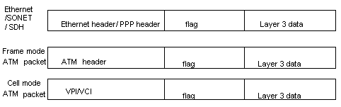
Figure 1-2 Label position in packet
In Ethernet packets and PPP packets, label stack lies between layer 2 header and layer 3 data, acting like a shim. In ATM cell mode packets, VPI/VCI is used as the label.
3) Label assignment and distribution
Label distribution refers to the process of creating a corresponding label switching path (LSP) for a FEC.
In the MPLS architecture, the decision to bind a particular label to a particular FEC is made by downstream LSR; after making the decision, the downstream LSR notifies the upstream LSR. That is to say, the label is assigned by the downstream LSR, and the assigned label is distributed from downstream to upstream.
Two label distribution modes are available in MPLS: downstream unsolicited (DU) mode and downstream on demand (DoD) mode.
l For a specific FEC, if LSR originates label assignment and distribution even without receiving label request message from upstream, it is in DU mode.
l For a specific FEC, if LSR begins label assignment and distribution only after receiving label request message from upstream, it is in DoD mode.
The upstream and downstream which have adjacency relation in-label distribution should reach agreement on label distribution mode.
To distribute labels to its peer, the LSR can use Label Distribution Protocol (LDP) messages or make the labels carried on other routing protocol messages.
& Note:
Upstream and downstream are just on a relative basis: For a packet forwarding process, the transmit router serves as upstream LSR and receive router serves as downstream LSR. Currently, the S9500 series adopt the DU label distribution mode.
4) Label assignment control mode
There are two modes to control the assignment and distribution of labels: independent mode and ordered mode.
In independent control mode, each LSR can send label mapping messages to the LSRs it connects to at anytime.
In ordered control mode, a LSR can send label mapping messages to upstream only when it receives a specific label mapping messages of the next hop of a FEC or the LSR serves as LSP (Label Switching Path) egress node.
& Note:
Currently, the S9500 series adopt the ordered label control mode.
5) Label retention mode
There are two label-retention modes: liberal label retention mode and conservative label retention mode.
Suppose there are two LSRs: Ru and Rd. For a specific FEC, if LSR Ru has received the label binding from LSR Rd, in case Rd is not the next hop of Ru and Ru saves this binding, then it is the liberal label retention. And if Ru discards this binding, then it is the conservative label retention mode.
In case it is required that LSR is capable of adapting route variation rapidly, you can use the liberal label retention mode. In case it is required that a few labels are saved in LSR, you can use the conservative label retention mode.
& Note:
Currently, the S9500 series adopt the liberal label retention mode.
1.2.3 LDP
Label distribution protocol (LDP) is the signaling control protocol in MPLS, which controls binding labels and FECs between LSRs and coordinates a series of procedures between LSRs.
1.3 MPLS Architecture
1.3.1 MPLS Network Structure
The basic composing unit of MPLS network is LSR (Label Switching Router). It runs MPLS control protocol and L3 routing protocol, exchanges routing messages with other LSRs and create the routing table, maps FECs with IP packet headers, binds FECs with labels, distributes label binding messages, establishes and maintains label forwarding table.
The network consisting of LSRs is called MPLS domain. The LSR that is located at the edge of the domain is called edge LSR (LER, Labeled Edge Router). It connects an MPLS domain with a non-MPLS domain or with another MPLS domain, classifies packets, distributes labels (as ingress LER) and distracts labels (as egress LER). The ingress LER is termed as ingress and egress LER as egress.
The LSR that is located inside the domain is called core LSR, which provides functions such as label swapping and label distribution. The labeled packets are transmitted along the LSP (Label Switched Path) composed of a series of LSRs.
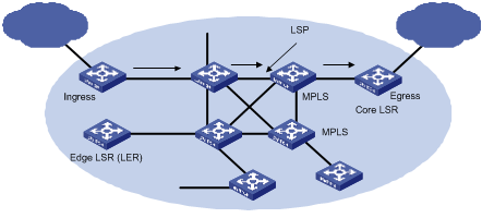
Figure 1-3 MPLS basic principle
1.3.2 Forwarding Labeled Packets
At the ingress, the packets entering the network are classified into FECs according to their characteristics. Usually, packets are classified into FECs according to the IP address prefix or host address. Packets in the same FEC pass through the same path (that is, LSP) in MPLS area. LSR assigns a short label of fixed length for the incoming FEC packet, and then forwards it through the corresponding interface.
On the LSR along the LSP, the mapping table of the import/export labels has been established (the element of this table is referred to as Next Hop Label Forwarding Entry (NHLFE)). When the labeled packet arrives, LSR only needs to find the corresponding NHLFE from the table according to the label and replace the original label with a new one, and then forwards the labeled packet. This process is called Incoming Label Map (ILM).
At the ingress, MPLS specifies a FEC for a specific packet, and the following routers only need to forward the packet by label switching, therefore this method is much simpler than general network layer forwarding and increases the forwarding speed.
& Note:
By default, if the TTL field of the outer label of an MPLS data packet is 0, the packet is dropped. However, you can configure the router to trap such a packet to the CPU by using the mpls settrap bad_ttl command. For details, refer to MPLS Commands.
1.3.3 Establishing LSP
Actually, the establishment of LSP refers to the process of binding FEC with the label, and then advertising this binding to the adjacent LSR on LSP. This process is implemented through LDP, which regulates the message in interactive processing and message structure between LSRs as well as routing mode.
I. LDP working process
Through sending Hello message periodically, an LSR finds its neighbor and then establish LDP session with the newly discovered adjacent LSR. By LDP session, the adjacent LSRs advertise such information as label switching mode, label space, session Keepalive timer value to each other. LDP session is a TCP connection, which needs to be maintained through LDP message. In case there is not any other LDP message during the time period specified by the session Keepalive timer value, and then it is necessary to send session Keepalive message to maintain the existence of LDP session. Figure 1-4 illustrates the diagram of LDP label distribution.
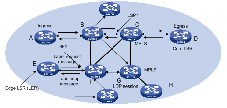
Figure 1-4 Label distribution process
For the label distribution mentioned previously, there are two modes: DoD and DU. The main difference between these two modes is that the label mapping messages are distributed actively or passively.
In DoD mode, the label is distributed in this way: the upstream LSR sends label request message (containing FEC descriptive information) to the downstream LSR, and the downstream LSR distributes label for this FEC, and then it sends the bound label back to the upstream LSR through label map message. The time when the downstream LSR feeds back the label map message depends on whether this LSR uses independent label control mode or sequential label control mode. When the sequential label control mode is used by the downstream LSR, the label map message is sent back to its upstream LSR if only it has received the label map message from its downstream LSR. And when the independent label control mode is used by the downstream LSR, then it will send label map message to its upstream LSR immediately, no matter whether it has received the returned label map message from its downstream LSR. Usually, the upstream LSR selects the downstream LSR according to the information in its routing table. In Figure 1-4, LSRs on the way along LSP1 use the sequential label control mode, and the LSR F on LSP2 uses independent label control mode.
In DU mode, the label is distributed in the following way: when LDP session is established successfully, the downstream LSR will actively distribute label map message to its upstream LSR. And the upstream LSR saves the label map information and processes the received label map information according to the routing table.
II. LSP loop control
While establishing LSP in MPLS domain, it is also necessary to prevent the presence of path loop. Then, such two methods as maximum hop count and path vector can be used.
The maximum hop count method refers to that the hop-count information is contained in the message bound with the forwarding label, and the value pluses one for each hop. When the value exceeds the threshold value, it is considered that a loop presents, and the process for establishing LSP is terminated.
The path vector method refers to that the path information is recorded in the message bound with the forwarding label, and, for every hop, the corresponding router checks if its ID is contained in this record. If not, the router adds its ID into the record; and if yes, it indicates that a loop presents and the process for establishing LSP is terminated.
1.3.4 LSP Tunnel and Hierarchy
I. LSP tunnel
MPLS supports LSP tunnel technology. On an LSP path, LSR Ru and LSR Rd are both the upstream and the downstream for each other. However, the path between LSR Ru and LSR Rd may not be part of the path provided by routing protocol. MPLS allows establishing a new LSP path <Ru R1...Rn Rd> between LSR Ru and LSR Rd, and LSR Ru and LSR Rd are respectively the starting point and ending point of this LSP. The LSP between LSR Ru and LSR Rd is referred to as the LSP tunnel, which avoids the traditional encapsulated tunnel on the network layer. If the route along which the tunnel passes and the route obtained hop by hop from routing protocol is consistent, this tunnel is called hop-by-hop routing tunnel. And if the two routes are not consistent, then the tunnel of this type is called explicit routing tunnel.
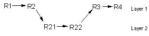
As shown in Figure 1-5, LSP <R2 R21 R22 R3> is a tunnel between R2 and R3.
II. Multi-layer label stack
In MPLS, a packet may carry multiple labels which are in the form of stack. Operations to the stack follow the “last in first out” principle and it is always the labels at the top of the stack that decide how to forward packets. Pushing label indicates to add a label into a outgoing packet, then the depth of the label stack is the former one plus 1, and the current label of the packet changes to the newly added one; popping a label indicates to remove a label form a packet, then the depth of the packet is the former one minus 1, and the current label of the packet changes to the label of its underlayer.
Multiple-layer label stack is used in LSP tunnel. When a packet travels in LSP tunnel, there will be multiple layers for the label of the packet. Then, at the ingress and egress of each tunnel, it is necessary to implement pushing and popping operation for the label stack. For each pushing operation, the label will be added with one layer. And there is no depth limitation for the label stack from MPLS.
The labels are organized according to the principle of “last in first out” in the label stack, and MPLS processes the labels beginning from the top of the stack.
If the depth of the label stack for a packet is m, it indicates that the label at the bottom of that stack is level 1 label, and the label at the top of the stack is level m label. A packet with no label can be regarded as a packet with empty label stack, that is, the depth of its label stack is 0.
1.3.5 MPLS and Other Protocols (Routing Protocols)
When LDP establishes LSP in hop-by-hop mode, the next hop is determined by using the information, which is usually collected by such routing protocols as IGP, BGP in each LSR route forwarding table, on the way. However, LDP just uses the routing information indirectly, rather than associates with various routing protocols directly.
On the other hand, although LDP is the special protocol for implementing label distribution, it is not the sole protocol for label distribution. The existing protocols such as BGP, RSVP, after being extended, can also support MPLS label distribution. For some MPLS applications, it is also necessary to extend some routing protocols. For example, the application of MPLS VPN requires extending the BGP protocol, thus the BGP protocol can propagate VPN routing information.
1.3.6 MPLS Application (MPLS-based VPN)
To transmit data stream of private network on public network, traditional VPN uses tunnel protocols like GRE, L2TP, and PPTP. LSP itself is a tunnel on public network, so there are obvious advantages to implement VPN by MPLS. MPLS VPN connects the geographically different branches of private network by using LSP, forming a united network. MPLS VPN also supports the interconnection between different VPNs.
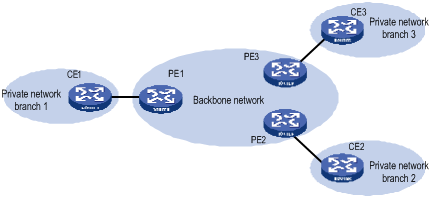
The basic structure of MPLS-based VPN is shown in Figure 1-6. CE is the customer edge device, and it may either be a router or a switch, or perhaps a host. PE is a service provider edge router, which is located on the backbone network. PE is responsible for the management of VPN customers, establishing LSP connection between various PEs, route allocation among different branches of the same VPN customer.
Usually the route allocation between PEs is implemented by using extended BGP. MPLS VPN supports the IP address multiplexing between different branches and the interconnection between different VPNs. Compared with traditional route, it is necessary to add branch and VPN identifier information in VPN route. So, it is necessary to extend BGP so as to carry VPN routing information.
Chapter 2 MPLS Basic Capability Configuration
This chapter covers the following topics:
l MPLS Basic Capability Overview
l Displaying and Debugging MPLS Basic Capability
l Typical MPLS Configuration Example
l Troubleshooting MPLS Configuration
2.1 MPLS Basic Capability Overview
Basic MPLS forwarding functions includes LDP session establishment and LSP path maintenance.
The typical configuration procedure for enabling basic MPLS functions on a routing switch is as follows:
1) Configure LSR ID
2) Enable MPLS
3) Enable LDP
4) Enter VLAN interface view and enable MPLS and LDP on the interface
Then the routing switch can provide MPLS forwarding and LDP signaling functions.
If you want to modify the default parameters or enable some special functions, for example, manually creating LSP or explicit route, you can configure according to the methods in configuration list. For some complicated functions, configuration combination may be required.
![]() Caution:
Caution:
It is not recommended to enable MPLS or LDP on the default VLAN interface.
2.2 MPLS Configuration
The following sections describe the required configuration tasks for MPLS basic capability:
l Enabling MPLS and Entering MPLS View
The following sections describe the optional configuration tasks for MPLS basic capability:
l Configuring the Topology-Driven LSP Setup Policy
l Configuring an LSP Setup Policy
2.2.1 Defining MPLS LSR ID
Before configuring any other MPLS command, it is necessary to configure LSR ID first. This ID is usually in IP address format and must be unique in the domain.
Perform the following configuration in the system view to define/delete an MPLS LSR ID:
|
To do... |
Use the command... |
|
Define LSR ID |
mpls lsr-id ip-address |
|
Delete LSR ID |
undo mpls lsr-id |
By default, LSR ID is not defined.
2.2.2 Enabling MPLS and Entering MPLS View
Perform the following operations in system view to enable/disable MPLS:
|
To do... |
Use the command... |
|
Enable MPLS globally and enter MPLS view (system view) Enable MPLS on a VLAN interface (VLAN interface view) |
mpls |
|
Disable MPLS globally or on a VLAN interface (system or VLAN interface view) |
undo mpls |
By default, MPLS is not enabled.
2.2.3 Configuring the Topology-Driven LSP Setup Policy
Perform the following operations in MPLS view to configure the topology-driven LSP setup policy:
|
To do... |
Use the command... |
|
Configure the topology-Driven LSP setup policy |
lsp-trigger { all | ip-prefix ip-prefix } |
|
Use the default value, which only allows 32-bit IP to trigger LSP |
undo lsp-trigger { all | ip-prefix ip-prefix } |
2.2.4 Configuring an LSP Setup Policy
Perform the following operations to configure an LSP setup policy:
|
To do... |
Use the command... |
|
Configure an LSP setup policy |
mpls ldp label-accept ip-prefix-name |
|
Cancel the LSP setup policy configured |
undo mpls ldp label-accept ip-prefix-name |
Perform the following configurations in system view to configure the advertisement of local distribution labels:
|
To do... |
Use the command... |
|
Configure the advertisement of local distribution labels |
mpls ldp label-advertise fec-ip-prefix [ lsr-ip-prefix ] [ swap-only ] |
|
Cancel the configuration of the advertisement of local distribution labels |
undo mpls ldp label-advertise { fec-ip-prefix | all } |
By default, the labels of all destination addresses are advertised to all LDP peers.
2.2.5 Configuring Static LSP
You can manually set an LSR to be a node along an LSP, and place a limit on the traffic over the LSP. Depending on the position in an MPLS domain, an LSR along an LSP can be the ingress node, an intermediate node (also called transit node), or the egress node. Note that an LSP operates normally only after all the LSRs along the LSP have been properly configured.
Perform the following configuration in MPLS view to set the local LSR to a node on a specified LSP:
|
To do... |
Use the command... |
|
Set the current LSR to the ingress node of the specified LSP |
static-lsp ingress lsp-name { destination dest-addr { addr-mask | mask-length } | l2vpn } nexthop next-hop-addr } } out-label out-label-value |
|
Cancel the ingress node setting of the specified LSP |
undo static-lsp ingress lsp-name |
|
Set the current LSR to an intermediate node along the specified LSP |
static-lsp transit lsp-name [ l2vpn ] incoming-interface interface-type interface-number in-label in-label-value nexthop next-hop-addr out-label out-label-value |
|
Cancel the intermediate node setting of the specified LSP |
undo static-lsp transit lsp-name |
|
Set the current LSR to the egress node of the specified LSP |
static-lsp egress lsp-name [ l2vpn ] incoming-interface interface-type interface-number in-label in-label-value |
|
Cancel the egress node setting of the specified LSP |
undo static-lsp egress lsp-name |
2.3 LDP Configuration
The following sections describe the required LDP configuration tasks for MPLS basic capability:
l Enabling LDP on a VLAN interface
The following sections describe the optional LDP configuration tasks for MPLS basic capability:
l Configuring Remote-Peer for Extended Discovery Mode
l Configuring session parameters
l Configuring LDP Loop Detection Control
l Configuring LDP Authentication Mode Between Every Two Switches
2.3.1 Enabling LDP protocol
To configure LDP, first enable LDP.
Perform the following configuration in the system view to enable/disable LDP:
|
To do... |
Use the command... |
|
Enable LDP protocol |
mpls ldp |
|
Disable LDP |
undo mpls ldp |
By default, LDP is disabled.
2.3.2 Enabling LDP on a VLAN interface
To make the VLAN interface support LDP, you must enable LDP function on the interface in VLAN interface mode. After enabling the LDP function, the interface then sets up session. It begins to set up LSP if in topology-driven mode,.
Disabling LDP function on interface causes the break of all LDP session in VLAN interface, and all the LSP based on those sessions are deleted. So you must use this command with cautiously.
Perform the following configuration in the interface view to enable/disable LDP on the interface:
|
To do... |
Use the command... |
|
Enable LDP function on the interface |
mpls ldp enable |
|
Disable LDP function on the interface |
mpls ldp disable |
By default, the interface LDP function is disabled.
2.3.3 Configuring Remote-Peer for Extended Discovery Mode
The Remote-peer configuration is mainly used for extended discovery mode so that this LSR can establish sessions with LSRs that are not directly connected with it at the link layer.
I. Enter Remote-peer view
Perform the following configuration in the system view to enter remote-peer view:
|
To do... |
Use the command... |
|
Enter Remote-peer view |
mpls ldp remote-peer index |
|
Delete the corresponding Remote-peer |
undo mpls ldp remote-peer index |
There is no default remote-peer.
II. Configuring an address for the Remote-peer
You can specify the address of any LDP-enabled interface on the Remote-peer or the address of the Loopback interface on the LSR that has advertised the route as the address of the Remote-peer.
Perform the following configuration in the Remote-peer view to configure a Remote-peer address:
|
To do... |
Use the command... |
|
Configure a remote-peer address |
remote-ip remoteip |
remoteip: the IP address of the Remote-peer. It should be the ID of the peer LSR.
2.3.4 Configuring session parameters
I. Configuring session hold-time
The LDP entity on the interface sends Hello packets periodically to find out LDP peer, and the established sessions must also maintain their existence by periodic message (if there is no LDP message, then Keepalive message must be sent).
& Note:
There are two types of LDP sessions: Basic and Remote. Basic session can be established only between LDP entities on two direct-connect switches, while Remote session can be established between LDP entities on two switches which are not directly connected. You can only configure Basic sessions in VLAN interface view and Remote sessions in remote-peer view.
![]() Caution:
Caution:
After modifying the holdtime parameter, run the mpls ldp reset-session command to reset the LDP session.
Perform the following operations in VLAN interface view to configure basic session hold-time:
|
To do... |
Use the command... |
|
Configure session hold-time |
mpls ldp timer { session-hold session-holdtime | hello hello-holdtime } |
|
Return to the default value |
undo mpls ldp timer { session-hold | hello } |
By default, the session-holdtime is 60 seconds and hello-holdtime is 15 seconds.
Perform the following operations in remote-peer view to configure remote session hold-time:
|
To do... |
Use the command... |
|
Configure session hold-time |
mpls ldp timer { targeted-session-hold | targeted-hello } {holdtime | interval } } |
|
Return to the default value |
undo mpls ldp timer { targeted-session-hold | targeted-hello } |
By default, targeted-session-hold holdtime is 60 seconds, and the interval is 24 seconds; targeted-hello holdtime is 45 seconds and the interval is 13 seconds.
II. Configuring Hello transport-address
The transport-address discussed here refers to the address carried in the transport address TLV in Hello messages. Generally, you can configure the transport-address to the MPLS LSR ID of the current LSR, but you can also configure the transport-address to other address flexibly as required by some applications.
Perform the following configuration in VLAN interface view to configure Hello transport-address:
|
To do... |
Use the command... |
|
Configure Hello transport-address |
mpls ldp transport-ip { interface | ip-address } |
|
Return to the default Hello transport-address |
undo mpls ldp transport-ip |
Transport-address defaults to the MPLS LSR ID of the current LSR.
If there are multiple links connecting two neighboring LSRs, all the LDP-enabled interfaces on the links connecting LSR and its neighbor must have the same transport address. You are recommended to use the same interface address for all of them, that is, LSR-ID.
![]() Caution:
Caution:
The interface with borrowed address is used on the LSR. You cannot use this interface address to set up the LDP session. You are recommended to use the LSR-ID instead.
2.3.5 Configuring LDP Loop Detection Control
I. Enabling loop detection
You can enable or disable the loop detection function during LDP signaling process. The loop detection includes maximum hop count mode and path vector mode.
The maximum hop count method refers to that the hop-count information is contained in the message bound with the forwarding label, and the value pluses one for each hop. When the value exceeds the threshold value, it is considered that a loop presents, and the process for establishing LSP is terminated.
The path vector method refers to that the path information is recorded in the message bound with the forwarding label, and, for every hop, the corresponding router checks if its ID is contained in this record. If not, the router adds its ID into the record; and if yes, it indicates that a loop presents and the process for establishing LSP is terminated. When this method is used, if the defined maximum value is exceeded, it is considered that a loop happens and the LSP establishment fails.
Perform the following configuration in the system view to enable loop detection:
|
To do... |
Use the command... |
|
Enable loop detection |
mpls ldp loop-detect |
|
Disable loop detection |
undo mpls ldp loop-detect |
By default, the loop detection is disabled.
![]() Caution:
Caution:
You need to enable the loop detection function on every device in a MPLS domain. Otherwise, the establishment of LDP sessions will be affected.
II. Setting the maximum hop count for loop detection
When maximum hop count mode is adopted for loop detection, the maximum hop-count value can be defined. And if the maximum value is exceeded, it is considered that a loop happens and the LSP establishment fails.
Perform the following configuration in the system view to set the maximum hop count for loop detection:
|
To do... |
Use the command... |
|
Set maximum hop count for loop detection |
mpls ldp hops-count hop-number |
|
Return to the default maximum hop count |
undo mpls ldp hops-count |
The maximum hop count of loop detection is 32 by default.
III. Setting the maximum hop count in path vector mode
When path vector mode is adopted for loop detection, it is also necessary to specify the maximum value of LSP path. In this way, when one of the following conditions is met, it is considered that a loop happens and the LSP establishment fails.
l The record of this LSR already exists in the path vector recording table.
l The path hop count exceeds this maximum value.
Perform the following configuration in the system view to set the maximum hop count in path vector mode:
|
To do... |
Use the command... |
|
Set the maximum hop count in path vector mode |
mpls ldp path-vectors pv-number |
|
Return to the default maximum hop count in path vector mode |
undo mpls ldp path-vectors |
The maximum of the maximum hop count of path vector is 32 by default.
2.3.6 Configuring LDP Authentication Mode Between Every Two Switches
Perform the following configuration in VLAN interface view or Remote-peer view to configure LDP authentication mode (between every two switches):
|
To do... |
Use the command... |
|
Configure LDP authentication Mode |
mpls ldp password [ cipher | simple ] password |
|
Remove LDP authentication |
undo mpls ldp password |
![]() Caution:
Caution:
There can be only one LDP session between any two devices. If you configure both a basic session and a remote session on a device, you need to configure the same authentication password for the two sessions.
2.4 Displaying and Debugging MPLS Basic Capability
2.4.1 Displaying and Debugging MPLS
I. Displaying static LSPs
|
To do... |
Use the command... |
Remarks |
|
Display the static LSP information |
display mpls static-lsp [ include text | verbose ] |
Available in any view |
II. Displaying the MPLS statistics information or LSP information of all ports or a single VLAN interface
|
To do... |
Use the command... |
Remarks |
|
Displaying the MPLS statistics information or LSP information of all ports or a single VLAN interface |
display mpls statistics { interface { Vlan-interface | all } | lsp { lsp-Index | all | lsp-name } |
Available in any view |
III. Displaying MPLS-enabled interfaces
|
To do... |
Use the command... |
Remarks |
|
Display information of the MPLS-enabled interfaces |
display mpls interface |
Available in any view |
IV. Displaying MPLS LSP information
|
To do... |
Use the command... |
Remarks |
|
Display the information about MPLS LSP |
display mpls lsp [ include text | verbose ] |
Available in any view |
V. Debugging MPLS
|
To do... |
Use the command... |
Remarks |
|
Enable debugging for MPLS LSP |
debugging mpls lspm { agent | all | event | ftn | interface | packet | policy process | vpn } |
Available in user view |
|
Disable debugging for MPLS LSP |
undo debugging mpls lspm { agent | all | event | ftn | interface | packet | policy process | vpn } |
Available in user view |
VI. Trap information of MPLS
This command is used to enable the trap function of MPLS during an LSP/LDP setup process.
Perform the following configuration in system view to enable/disable the trap function of MPLS:
|
To do... |
Use the command... |
|
Enable the LDP Trap function of MPLS |
snmp-agent trap enable ldp |
|
Disable the LDP Trap function of MPLS |
undo snmp-agent trap enable ldp |
|
Enable the LSP Trap function of MPLS |
snmp-agent trap enable lsp |
|
Disable the LSP Trap function of MPLS |
undo snmp-agent trap enable lsp |
2.4.2 Displaying and Debugging LDP
I. LDP display commands
|
To do... |
Use the command... |
Remarks |
|
Display LDP information |
display mpls ldp |
Available in any view |
|
Display buffer information for LDP |
display mpls ldp buffer-info |
Available in any view |
|
Display LDP-enabled interface information |
display mpls ldp interface |
Available in any view |
|
Display LDP saved label information |
display mpls ldp lsp |
Available in any view |
|
Display information on all peers of LDP session |
display mpls ldp peer |
Available in any view |
|
Display information of the remote-peers in the LDP sessions |
display mpls ldp remote |
Available in any view |
|
Display states and parameters of LDP sessions |
display mpls ldp session |
Available in any view |
II. LDP debugging commands
|
To do... |
Use the command... |
Remarks |
|
Enable debugging for MPLS LDP |
debugging mpls ldp { all | main | advertisement | session | pdu | notification | remote | filter } [ interface interface-type interface-number ] |
Available in user view |
|
Disable debugging for MPLS LDP |
undo debugging mpls ldp { all | main | advertisement | session | pdu | notification | remote | filter } [ interface interface-type interface-number ] |
Available in user view |
III. Reset LDP
|
To do... |
Use the command... |
Remarks |
|
Reset a specific LDP session on the VLAN interface (VLAN interface view) |
mpls ldp reset-session peer-address |
Available in user view |
2.5 Typical MPLS Configuration Example
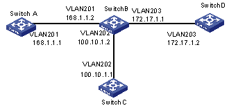
I. Network requirements
Figure 2-1 illustrates a network with four switches, which connects to each other through Ethernet.
The four switches all support MPLS, and LSP can be established between any two switches with the routing protocol OSPF. LDP establishes LSP by using routing information of OSPF.
II. Network diagram
III. Configuration procedure
1) Configure Switch A
# Configure LSR ID and enable MPLS and LDP.
[H3C] mpls lsr-id 168.1.1.1
[H3C] mpls
[H3C-mpls] quit
[H3C] mpls ldp
# Configure IP address and enable MPLS and LDP for VLAN interface 201.
[H3C] vlan 201
[H3C-vlan201] port gigabitethernet 2/1/1
[H3C-vlan201] quit
[H3C] interface Vlan-interface 201
[H3C-Vlan-interface201] ip address 168.1.1.1 255.255.0.0
[H3C-Vlan-interface201] mpls
[H3C-Vlan-interface201] mpls ldp enable
[H3C-Vlan-interface201] mpls ldp transport-ip interface
# Enable OSPF on the interface connecting Switch A with Switch B.
[H3C] Router id 168.1.1.1
[H3C] ospf
[H3C-ospf-1] area 0
[H3C-ospf-1-area-0.0.0.0] network 168.1.0.0 0.0.255.255
2) Configure Switch B
# Configure LSR ID and enable MPLS and LDP.
[H3C] mpls lsr-id 172.17.1.1
[H3C] mpls
[H3C-mpls] quit
[H3C] mpls ldp
# Configure IP address and enable MPLS and LDP for VLAN interface 201.
[H3C] vlan 201
[H3C-vlan201] port gigabitethernet 2/1/1
[H3C-vlan201] quit
[H3C] interface vlan-interface 201
[H3C-Vlan-interface201] ip address 168.1.1.2 255.255.0.0
[H3C-Vlan-interface201] mpls
[H3C-Vlan-interface201] mpls ldp enable
[H3C-Vlan-interface201] mpls ldp transport-ip interface
# Configure IP address and enable MPLS and LDP for VLAN interface 203.
[H3C] vlan 203
[H3C-vlan203] port gigabitethernet 2/1/3
[H3C-vlan203] quit
[H3C] interface vlan-interface 203
[H3C-Vlan-interface203] ip address 172.17.1.1 255.255.0.0
[H3C-Vlan-interface203] mpls
[H3C-Vlan-interface203] mpls ldp enable
[H3C-Vlan-interface203] mpls ldp transport-ip interface
# Configure IP address and enable MPLS and LDP for VLAN interface 202.
[H3C] vlan 202
[H3C-vlan202] port gigabitethernet 2/1/2
[H3C-vlan202] quit
[H3C] interface Vlan-interface 202
[H3C-Vlan-interface202] ip address 100.10.1.2 255.255.255.0
[H3C-Vlan-interface202] mpls
[H3C-Vlan-interface202] mpls ldp enable
[H3C-Vlan-interface202] mpls ldp transport-ip interface
[H3C-Vlan-interface202] quit
# Enable OSPF on the interfaces respectively connecting Switch B with Switch A, Switch D and Switch C.
[H3C] Router id 172.17.1.1
[H3C] ospf
[H3C-ospf-1] area 0
[H3C-ospf-1-area-0.0.0.0] network 168.1.0.0 0.0.255.255
[H3C-ospf-1-area-0.0.0.0] network 172.17.0.0 0.0.255.255
[H3C-ospf-1-area-0.0.0.0] network 100.10.1.0 0.0.0.255
[H3C-ospf-1-area-0.0.0.0] quit
3) Configure Switch C
# Configure LSR ID and enable MPLS and LDP.
[H3C] mpls lsr-id 100.10.1.1
[H3C] mpls
[H3C-mpls] quit
[H3C] mpls ldp
# Configure IP address and enable LDP and MPLS for VLAN interface 202.
[H3C] vlan 202
[H3C-vlan202] port gigabitethernet 2/1/1
[H3C-vlan202] quit
[H3C] interface Vlan-interface 202
[H3C-Vlan-interface202] ip address 100.10.1.1 255.255.255.0
[H3C-Vlan-interface202] mpls
[H3C-Vlan-interface202] mpls ldp enable
[H3C-Vlan-interface202] quit
# Enable OSPF on the interface connecting Switch C with Switch B.
[H3C] Router id 100.10.1.1
[H3C] ospf
[H3C-ospf-1] area 0
[H3C-ospf-1-area-0.0.0.0] network 100.10.1.0 0.0.0.255
4) Configure Switch D
# Configure LSR ID and enable MPLS and LDP.
[H3C] mpls lsr-id 172.17.1.2
[H3C] mpls
[H3C-mpls] quit
[H3C] mpls ldp
# Configure IP address and enable MPLS and LDP for VLAN interface 203.
[H3C] vlan 203
[H3C-vlan203] port gigabitethernet 2/1/3
[H3C-vlan203] quit
[H3C] interface vlan-interface 203
[H3C-Vlan-interface203] ip address 172.17.1.2 255.255.0.0
[H3C-Vlan-interface203] mpls
[H3C-Vlan-interface203] mpls ldp enable
# Enable OSPF on the interface connecting Switch D with Switch B.
[H3C] Router id 172.17.1.2
[H3C] ospf
[H3C-ospf-1] area 0
[H3C-ospf-1-area-0.0.0.0] network 172.17.0.0 0.0.255.255
2.6 Troubleshooting MPLS Configuration
Symptom: Session cannot be setup with the peer after LDP is enabled on the interface.
Troubleshooting:
Cause 1: Loop detection configuration is different at the two ends.
Solution: Check loop detection configuration at both ends to see if one end is configured while the other end is not (this will result in session negotiation failure).
Cause 2: Local machine cannot get the route to peer LSR ID, so TCP connection cannot be set up and session cannot be established.
Solution: The default address for session transfer is MPLS LSR ID. The local machine should issue the LSR ID route (often the Loopback address) and lean the peer LSR ID route.